
Forme 2 MBHF2LW - Heating Martec - Free user manual and instructions
Find the device manual for free Forme 2 MBHF2LW Martec in PDF.


| Product Type | Fan Heater |
| Brand | Martec |
| Model | Forme 2 MBHF2LW |
| Dimensions (Approx.) | 20 x 15 x 10 cm (7.9 x 5.9 x 3.9 in) |
| Weight (Approx.) | 1 kg (2.2 lbs) |
| Power Supply | 220-240 V, 50/60 Hz |
| Power Consumption | 1500 W (max) |
| Heat Settings | 2 (Low/High) |
| Fan Only Mode | Yes |
| Thermostat | Adjustable |
| Overheat Protection | Yes |
| Tip-Over Safety Switch | Yes |
| Cool Touch Housing | Yes |
| Maintenance | Clean air inlet/outlet with soft cloth; do not immerse in water |
| Filter Cleaning | Every 2 weeks; vacuum or wash with mild detergent |
| Spare Parts Availability | Contact Martec support for replacement parts |
| Repair Information | Refer to user manual or authorized technician |
| Noise Level (Approx.) | 45 dB (low setting) |
| Certifications | CE, RoHS |
Frequently Asked Questions - Forme 2 MBHF2LW Martec
User questions about Forme 2 MBHF2LW Martec
0 question about this device. Answer the ones you know or ask your own.
Ask a new question about this device
Download the instructions for your Heating in PDF format for free! Find your manual Forme 2 MBHF2LW - Martec and take your electronic device back in hand. On this page are published all the documents necessary for the use of your device. Forme 2 MBHF2LW by Martec.
USER MANUAL Forme 2 MBHF2LW Martec
Thank you for selecting Martec Bathroom Heater 3 in 1. Please read all instructions before commencing installation.
IMPORTANT: This unit must be installed to comply with the appropriate council regulations and the Australia and New Zealand wiring rules AS/NZS3000:2000 or lastest edition thereof.
The main supply and interconnecting cables required for installation of this unit are not included.
WARNING - INSTALLATION ONLY TO BE BY QUALIFIED PERSONS
-
Use this heater only as described in this manual. The manufacturer does not recommend any other use as this may cause fire, electric shock, or injury to persons. If you have questions, contact the manufacture or local agent.
-
All wiring must be carried out by a Licensed Electrician in accordance with all applicable codes and standards.
-
Make sure the power is off before the installation.
-
When cutting into the wall, do not damage electrical wiring and other hidden utilities.
-
The heater must be properly grounded
-
The lamps are hot when in use. Do not touch the infrared lamps with any part of your body when in use.
-
For the purpose of avoiding any dangerous gas leaking into your bathroom, the ventiduct of the heater must not be laid together with the ventiduct of air-fueled water heater or other open-fire appliances into the same flue.
-
The disconnection may be achieved by having the plug accessible or by incorporating a switch in the fixed wiring in accordance with the wiring rules. The heater must be isolated from the power by means of a plug or all-pole disconnection switch with a contact separation of at least 3mm in each pole.
-
The power cable must stand a minimum 5A load.
-
The appliance is not intended for use by persons (including children) with reduced physical, sensory or mental capabilities, or lack of experience and knowledge, unless they have been given supervision or instruction concerning use of the appliance by a person responsible for their safety.
-
Children should be supervised to ensure that they do not play with the appliance.
-
The heater is to be installed so that switches and other controls cannot be touched by a person in the bath or shower.
-
The appliance shall, under no circumstances, be covered with insulating material or similar material.
-
Regulations concerning the discharge of air have to be fulfilled.
-
Joists, beams and rafters shall not be cut or notched to install the appliance.
IMPORTANT CONSIDERATIONS BEFORE INSTALLING
A few minutes of planning can make a big difference to the installation time and also to your satisfaction with the function of the unit.
-
The unit should not be installed directly above a shower or bathtub. The unit must not be installed in a position where water may splash onto the lamps.
-
The unit must not be installed beneath a fixed socket.
-
The unit is designed for installation in flat ceilings only. Do not mount it on a sloping ceiling or a vertical wall.
-
The infrared lamps are most effective when you are standing directly beneath them, so generally the unit would be mounted a place where you would stand to dry yourself
-
For the exhaust fan to work efficiently, replacement air of a volume equivalent to what is being extracted must be able to enter the room. Generally, this air would be drawn under the door, or through a slightly open window. If the room is airtight, the fan will function poorly
-
Before commencing any cutting, check in the ceiling space that there are no obstructions such as ceiling joists and that there is sufficient height clearance for the housing. Check that the electrical wiring can be routed from the wall switches to the mounting location.
INSTALLATION
- Cutting a vent
Locate a vent position (above the ceiling) on the wall, and then cut a 105mm diameter hole at this very position.
- Ducting
Put one end of the 100mm diameter ventiduct into the vent hole and seal space around the hole using a suitable sealant and cowling where necessary.
Note: Since the length of each duct is 1.5m, make sure that from the centre of installation position there should be a distance within 1.5m to the outside vent.

Wall venting shown
- Locating the heater
For the purpose of obtaining best healing effect, from the lamps there should be a distance of about a 2.3mtr overall height to ground.
- Prepare the ceiling
Cut around the included hole-cutting template and use this template to mark the hole outline on the ceiling. Note the Hole Cut Out Size is 375mmx 202mm for this unit.
Make sure a distance between the
edges and wall is no less than 250mm. Also from the rooftop should be a
minimum 220mm height to the ceiling. 5. Remove the Fascia
Remove the 2 lamps from the heater.
Unclip the internal fascia-retaining
springs inside the housing. Remove
the fascia, connect the ducting if required

to the outer grill of the wall unit into the square hole being sure to pull the side springs inward so that the body can pas through the hole without damaging the plaster. Ensure that the unit
is held securely in place by the clips. If required, additional screws can be used to aid
holding the unit into the ceiling. Screw holes are provided in the flange for this purpose
Reconnect the LED down light plugs hold the fascia against the body of the heater and the
ceiling and attach the securing springs to hold the fascia in-place., replace the Heat Lamps
ensure good electrical contact, but do not over tighten.
6. ELECTRICAL WIRING
The bathroom heater unit must be wired through either a plug and socket or an all-pole disconnecting switch (SW 1) in accordance with Australian Wiring Rules AS/NZS3000.
Note: This unit is fitted with a thermostat switch which will operate to automatically switch the fan on in the event that the internal temperature of the unit exceeds 80^ C.
Fit the wires to the nominated location on the terminal block on back of wall switch plate.
Connect the wiring to the three switches as shown in the below electrical diagram. Note: a. Ensure that the power is turned off before carrying out any work on electrical installations.
b. Remove the terminal cover on the heater unit and wire accordingly to the label
adjacent to the terminal B lock, Make sure all cables are securely connected and refit the terminal cover.
c. Clean the fascia and globes with a soft moist cloth. Turn on power and check the switch operation.
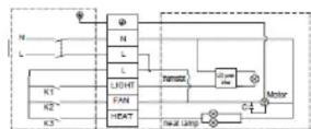
TERMINAL BLOCK
220-240V\~50Hz
LIGHT: 10W led downlight
HEATER: 2×275W
FAN:45W
FORME 2 INSTALLATION INSTRUCTIONS Model No : MBHF2LW
Continued:
-
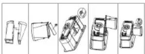
Locate and fit the duct to the ducting outlet, be sure to secure properly over the duct outlet. Use clamp supplied or zip tie to secure duct (tighten so that it will not come of during operation)
-
Position the housing into the hole
Choose and optimal direction to put the housing into the hole in
accordance with the position of the fan outlet. Use the two spring clips to fix to the housing. Ensure that the unit is held securely by the clips.
Note: Try to keep the redundant wire away from the housing.
- Final installation
1) Replace the fascia
Replace the fascia and retaining springs.
2) Replace the lamps
Ensure the lamps are tightened sufficiently to make good electrical contact. Clean the lamps and fascia.
3) Fix the switch panel to the wall
Note: The switch wiring should be mounted inside the wall to give the switch an integrated built in appearance. If it is necessary to run the wiring on the outside of the wall, use a suitable conduit and fixings to properly located and hold the wiring used.
For the exhaust fan to work efficiently,
replacement air of a volume equivalent to what is being extracted must be able to enter the room. In general this air would be drawn from under the door, or through a slightly opened window.
If the room is air-tight, the fan will function poorly.
ASSEMBLY OF THE DUCT KIT TO UNIT
Note
Our bathroom heater uses the infrared heating lamps as a source of heat. It also combines the functions of exhaust and light.
1. Heat
Turn on/off 'HEAT' button.
Each individual infrared lamp has been sprayed 4 times with cold water to ensure that there are no flaws in the construction.
Do not touch the infrared lamps with any part of your body when in use.
2 Exhaust
Turn on/off'FAN' button.
The heater can exhaust odour and steam in a quick and efficient way by turning on the 'FAN' button.
Note: No additional exhaust fan is necessary for the heater itself can exhaust all odour and steam as needed.
- Lighting
Turn on/off 'LIGHT' button.
Note: Do not turn on/off the buttons frequently when in use. Shut off power if in long vacancy.
MAINTENANCE
- Clean
1) Shut off power before cleaning.
2) Wipe lamps and fascia with care using a soft cloth soaked with neutral detergent. Note: Ensure the lamps are cool to touch before handling.
2. Replacement Globes
- Check and tighten lamps regularly.
2 Shut off power before replacement.
3 Use E27 275W infrared lamps for heating(MARTEC Code: MRL275W).
4 Centre Lamp 10Watt ( Tri Colour LED Down-light) available from Martec Pty Ltd
Note: It may affect operation (even cause danger) when lamps, other than the designated ones, are used.
WARRANTY
The unit is warranted against defects in manufacturing and workmanship for a period of 2 years. The warranty does not extend to lamp globes supplied or installation of the unit or any associated wiring or any damage caused by installation or wiring. The installation must be conducted by a licensed electrician and a suitable certificate of safety is to be issued by the electrician who installed the unit. Warranty claims will be voided unless a certificate of safety can be produced when required, prior to service or repair.
This warranty does not cover damages or loss caused by: Heat or light lamps.
- Any consequential losses arising from incorrect installation or operation or maintenance of this product.
- Any consequential losses arising from incorrect wiring of this product.
- Any modifications or changes made to the unit, other than those recommended by the Manufacturer
ACCC Required Statement
Our goods come with guarantees that cannot be excluded under the Australian Consumer Law. You are entitled to Marlee replacing the product in home with parts and labour for a major failure. You are also entitled to have the goods repaired or replaced if the goods fail to be of acceptable quality and the failure does not amount to a major failure. Martec offers an in home warranty that includes parts and labour so the end consumer is not out of pocket.
Note: The Hole Cut Out Size is 375mm x 202mm for this unit.
MAIN TECHNICAL PARAMETERS
| Model Number | MBHF2LW |
| Rated Voltage | 220V-240V |
| Rated Frequency | 50Hz |
| Rated Total Power | 605W |
LIST OF ACCESSORIES
| Operation unit | 1 piece |
| Infrared lamp 275W (E27) | 2 pieces |
| Light10 Watt SMDTricolour ( Size Dia 83x45) Available from Martec | 1 piece |
| Installation instruction & separate hole-cutting template | 1 piece |
| Warranty card | 1 piece |
| Venliduct kit | 1 set |
| Duct clip | 1 piece |
| Switch | 1 piece |
Airflow : 300m³/h
Airflow volume data is tested in accordance with the ISO standard.
Name:
Contact No:
Address:
Fill out the following details and file with the purchase invoice for warranty service.
MODEL NO.: MBHF2LW
Purchased from:
Date of purchase:
/// MARTEC PTY LTD ABN: 82599302308
We reserve the rights to revise this instruction without any prior notice.
Contact details for after sales service.
Phone: 02 8778 7500
Fax: 0287787555
- WARNING - INSTALLATION ONLY TO BE BY QUALIFIED PERSONS
- IMPORTANT CONSIDERATIONS BEFORE INSTALLING
- INSTALLATION
- ELECTRICAL WIRING
- FORME 2 INSTALLATION INSTRUCTIONS Model No : MBHF2LW
- MAINTENANCE
- Replacement Globes
- Note: The Hole Cut Out Size is 375mm x 202mm for this unit.
- Name:
- Address:
- MODEL NO.: MBHF2LW
- /// MARTEC PTY LTD ABN: 82599302308
- Contact details for after sales service.
- Phone: 02 8778 7500
- Fax: 0287787555
Brand : Martec
Model : Forme 2 MBHF2LW
Category : Heating