
WM-L640V - Television LG - Free user manual and instructions
Find the device manual for free WM-L640V LG in PDF.


| Product Type | Wall Mounting Bracket for Multi-Vision Displays |
| Model Numbers | WM-L640V, WM-P640V |
| Compatible Display Sizes | 47-inch and 55-inch Multi-Vision units |
| Max Tensile Load | 40 kgf (392 N) |
| VESA Standard | 600 x 400 mm |
| Dimensions (WM-L640V for 47-inch) | 1043.9 x 589 x 44.5 mm (WxHxD) |
| Dimensions (WM-L640V for 55-inch) | 1212.4 x 683.2 x 44.5 mm |
| Dimensions (WM-P640V for 47-inch) | 589 x 1043.9 x 44.5 mm (WxHxD) |
| Dimensions (WM-P640V for 55-inch) | 683.2 x 1212.4 x 44.5 mm |
| Weight (WM-L640V) | 12 kgf |
| Weight (WM-P640V) | 10.9 kgf |
| Package Dimensions | 1180 x 725 x 140 mm |
| Vertical Adjustment Range | Approx. 15 mm (WM-L640V), 11 mm (WM-P640V) |
| Horizontal Adjustment Range | Approx. 263 mm (WM-L640V for 47-inch), 431 mm (WM-L640V for 55-inch); 85 mm (WM-P640V for 47-inch), 179 mm (WM-P640V for 55-inch) |
| Forward/Backward Adjustment | Min. approx. 10 mm forward/backward |
| Included Components | Wall Mounting Bracket, Anchors (12 pcs), Screws (12 pcs for wall, 4 pcs for inter-product), Guide Spacers (4 pcs), Guide Spacer Fixing Screws (4 pcs), Safety Clips (2 pcs), Owner's Manual |
| Material | Metal (steel) with corrosion-resistant coating |
| Installation Requirements | Professional installation, concrete or solid wall, drill depth 80-100 mm, drill bit Ø8 mm |
| Safety Features | Safety screws (black) for transport, safety clips to prevent loosening |
| Compliance | UL/CE certified (assumed) |
Frequently Asked Questions - WM-L640V LG
User questions about WM-L640V LG
0 question about this device. Answer the ones you know or ask your own.
Ask a new question about this device
Download the instructions for your Television in PDF format for free! Find your manual WM-L640V - LG and take your electronic device back in hand. On this page are published all the documents necessary for the use of your device. WM-L640V by LG.
USER MANUAL WM-L640V LG
Wall Mounting Bracket
Please read this manual carefully before operating the your set and retain it for future reference.
WM-L640V
WM-P640V
CONTENTS
3 SAFETY INSTRUCTIONS
4 Precaution in Installation
4 Precaution in Movement
5 PRODUCT COMPOSITION
6 INSTALLATION GUIDE
6 Preparing the Multi-Vision to Be Attached to Product
7 Fixing the Product to Wall
10 Connecting Multiple Products
12 Mounting a Multi-Vision to the Product
14 TRANSFORMATION OF PRODUCT
14 Reassembly for 55-in Multi-Vision
16 PRODUCT OPERATION
18 PRODUCT SPECIFICATIONS
SAFETY INSTRUCTIONS
If you are a professional installer, please read this manual carefully before installing the product.
After installing the product according to the manual, ensure that the user also reads the manual carefully.
After reading the manual, please keep it handy for future reference.

WARNING
The product should be installed by a qualified professional specified by the retail store.
Installing the product without a qualified professional is dangerous and may cause personal injury.
When moving or replacing the product after installation, contact a qualified installer specified by the retail store.
Installation or movement of the product must be carried out by a skilled professional. If unqualified persons move and install the product, it may cause safety issues.
The product should be installed where its weight can be fully supported.
If the product is installed on a weak surface, the product may fall, causing injury.
Do not hang on this product or apply any shock to it.
The product may fall and cause injury.

CAUTION
Follow the instructions in the manual to properly install this product.
If you do not follow the instructions, the product may be installed incorrectly and cause serious injury or damage to the product.
During installation, check whether the wall is strong enough to hold the product and use the anchors and screws provided.
If you use anchors and screws that are not specified by the manufacturer, they may not hold the weight of the product, causing safety issues.
Do not clean the product with wet towels and do not place a heater or humidifier underneath it.
Moisture permeating into the product, including through steam and heat, may result in a fire, electric shock or damage to the product.
Make sure that the power cord is removed from the outlet before installing the product.
Otherwise, it may cause an electric shock or fire. To install or adjust the height of the product, two or more people are needed.
If you try to install or move the product alone, it may fall, causing injury or damage to the product.
When drilling holes into the wall, make sure you use a drill and drill bit with the specified diameter. Ensure that you also follow the instructions regarding the depth of the holes.
Otherwise, the product may be installed incorrectly and cause safety issues.
Keep this product away from sprinklers, sensors, high-tension wires, and power sources.
Do not install it in a location where vibrations or impact shocks are likely to occur.
Wear working gloves when installing the product. Do not use bare hands.
Otherwise, it may cause personal injury.
Precaution in Installation

WARNING
Check the wall material and thickness of the finishing material.
You can use the anchors and screws provided with the TV set for the wall made with concrete, lightweight concrete, soft fieldstone, hard fieldstone, brick or cellular block.
Do not mount the device on walls made with plaster board or medium-density fiberboard (MDF). In this case, the anchor and screws must be inserted into the concrete behind the finish. If there is no concrete on the other side, then you must install a separate hanger first to fix the anchors and bolts to.
When installing it on a wall not specified in this manual, make sure each fixing point withstands an uplifting load of 70 kgf (686 N) and a shearing load of 100 kgf (980 N) or more.
The weight of the Multi-Vision installed on the product must be equal to or less than 40 kgf.
Precautions when mounting Multi-Visions
When installing multiple Multi-Visions, be careful to avoid vertical and horizontal impacts between the Multi-Visions. Strong shocks may cause the Multi-Visions to malfunction.

Precaution in Movement

WARNING
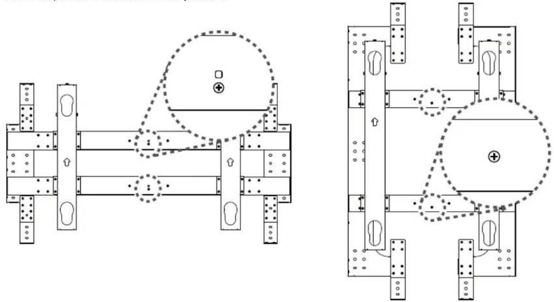
When transporting the product, check whether the safety screws (black) are fastened to the location illustrated in the figure below. If the safety screws (black) are not fastened, it may result in personal injury due to an unexpected movement of the product.
PRODUCT COMPOSITION
Please check whether all the components are included in the box before using the product. If there are any missing components, contact the retailer where you purchased the product. Note that the accessories may look different from those shown here.

Wall Mounting Anchor, 12 EA
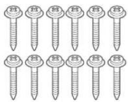
Wall Mounting Bracket Fixing Screw (Used for fixing to wall) (Φ5 x L65) 12 EA

Wall Mounting Bracket
Fixing Screw
(Used for inter-product fixing)
(M4 x L10) 4 EA

Guide Spacer, 4 EA Guide Spacer Fixing Screw
(M6 x L40) 4 EA


Safety Clip, 2 EA
Owner's Manual

CAUTION
• Always use genuine components to ensure safety and product performance.
- The product warranty will not cover damage or injury caused by the use of counterfeit components.

NOTE
- The accessories supplied with your product may vary depending on the model.
- Without prior notice, all information and specifications in this manual are subject to change to improve the performance of the product.
INSTALLATION GUIDE
Preparing the Multi-Vision to Be Attached to Product
- The picture may differ from the actual product.
1 Place the multi-vision on a table with its screen facing downward.
- Make sure that you place it on soft clothing or a cushion on the flat surface
2 Remove any screws that have been installed on the fixing area of the multi-vision wall mounting bracket.
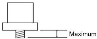
3 Check if the guide spacer is at the maximum value.
4 Place the guide spacers over the screw holes on the Multi-Vision. Tighten the guide spacers with the guide spacer fixing screws (M6 x L40).
5 Turn the screw until the gap between the guide spacer and the Multi-Vision has about 1 mm remaining.


NOTE
- If the screws are not fully tightened when you fix the guide spacers, check the length of the screws and refer to the technical service manual.
Fixing the Product to Wall
1 On the position where the wall mounting anchor will be fixed, drill a hole with a depth of between 80 mm - 100 mm using a drill bit 8 mm.
- Use the 8 mm drill bit for concrete and a hammer (impact) drill.

2 Clean out the drilled hole.
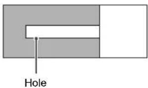
3 Insert the wall mount anchor to the hole (using a hammer).

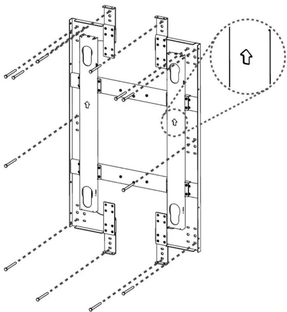
4 Place the wall mounting bracket close to the wall along the hole.
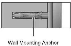
5 Insert the wall mounting screw into the hole and tighten it.
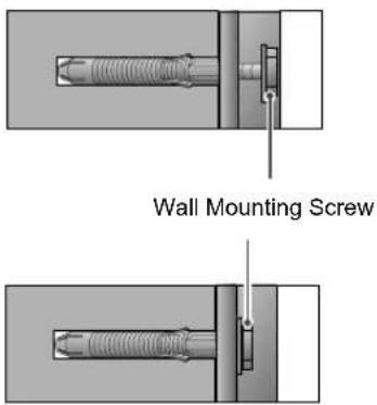
Install the product on the wall using the fixing screws for the wall mounting bracket. Install the product with the arrow marked on it facing upward.
WM-L640V

WM-P640V

Connecting Multiple Products
- The picture may differ from the actual product.
1 Connect the fixing screws for wall mounting bracket on the up, down, left and right side.
2 Insert the fixing screws to the holes as shown in the figure and turn them.
WM-L640V

WM-P640V

Mounting a Multi-Vision to the Product
- The picture may differ from the actual product. Please install in the following order:
1 Check if the up/down adjustment piece is located at the uppermost position.
2 Remove the two safety screws. If the safety screw is fastened, the product cannot be moved to the left or right.
3 As shown in the figure, hang the multi-vision combined to the guide spacer using the holes on the product.
4 Align the height of the product and the Multi-Vision by adjusting the up/down adjustment piece downwards.
- If you install multiple products, accurately align the products and the Multi-Vision from bottom to top.
Otherwise, installing products that will be located at the top will be difficult.
5 Fit a safety clip to prevent the installed multi-vision from coming loose. It should be inserted to the guide spacer hole at the bottom of both sides.
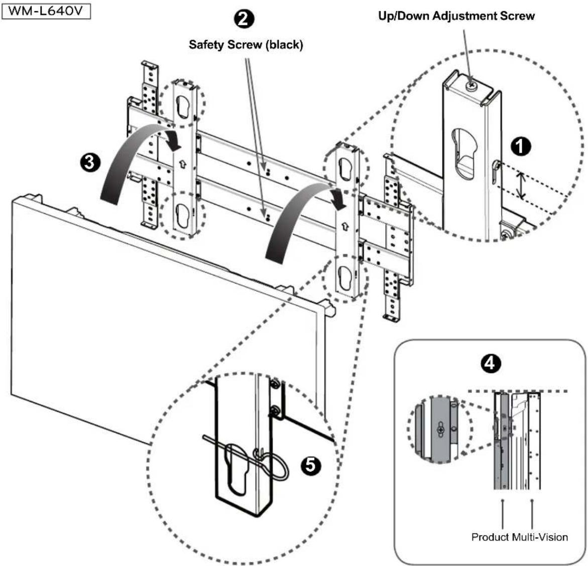
WM-P640V

TRANSFORMATION OF PRODUCT
Reassembly for 55-in Multi-Vision
- The picture may differ from the actual product.
WM-L640V
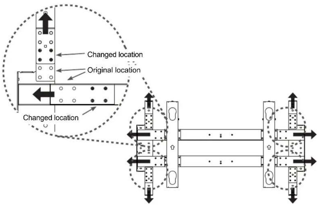
1 Remove the screws (32 pieces) shown in the red dotted-line circle in the figure below.

2 If you move the bracket in other directions, you can see all of the screw holes that are in different locations. Reassemble the bracket by fastening the screws (32 pieces).
WM-P640V
1 Remove the screws (32 pieces) shown in the red dotted-line circle in the figure below.

2 If you move the bracket in other directions, you can see all of the screw holes that are in different locations. Reassemble the bracket by fastening the screws (32 pieces).
3 When the assembly is completed, fasten the safety screws (black) for safety during transport. The safety screws (black) can be fastened when the product is aligned in the center.

PRODUCT OPERATION
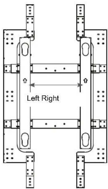
Horizontal Adjustment
WM-L640V

| Product Type Left Right | ||
| Product for 47-inch Multi-Vision only | 131.5 mm 131.5 mm | |
| Product for 55-inch Multi-Vision only | 215.5 mm 215.5 mm | |
WM-P640V
| Product Type Left Right | ||
| Product for 47-inch Multi-Vision only | 42.5 mm 42.5 | mm |
| Product for 55-inch Multi-Vision only | 89.5 mm 89.5 | mm |

CAUTION
- When sliding the product to the left or right, be careful to prevent injury to your hands.
Vertical Adjustment

Turn this part to make the vertical adjustment.
The figure shows the WM-L640V model. For the WM-P640V model, you can also make the vertical adjustment.
Back & Forth Adjustment
From the back or side of the product, use a Phillips screwdriver or a hexagon socket screw key in the guide spacer hole and turn the guide spacer to move the Multi-vision forward or backward.
If you turn the guide spacer counterclockwise from the back of the product, the Multi-vision moves forward. If you turn it clockwise, the Multi-vision moves backward.

The figure shows the WM-L640V model. For the WM-P640V model, you can also make the back & forth adjustments by turning the guide spacer.
PRODUCT SPECIFICATIONS
WM-L640V
(Unit : mm)

| Product dimensions (Width x Height x depth) | Product for 47-inch Multi-Vision only | 1043.9 mm x 589 mm x 44.5 mm |
| Product for 55-inch Multi-Vision only | 1212.4 mm x 683.2 mm x 44.5 mm | |
| Package dimensions (width x height x Depth) | 1180 mm x 725 mm x 140 mm | |
| Wall Mounting VESA specifications | 600*400 | |
| Weight (kgf) 12 kgf | ||
| Max. tensile load (kgf) 40 kgf | ||
| Position adjustment Vertical adjustment in total: approx. 15 mmHorizontal adjustment in total: approx. 263 mm(Product for 55-inch Multi-Vision only approx. 431 mm)Forward: min. approx. 10 mm | ||
WM-P640V
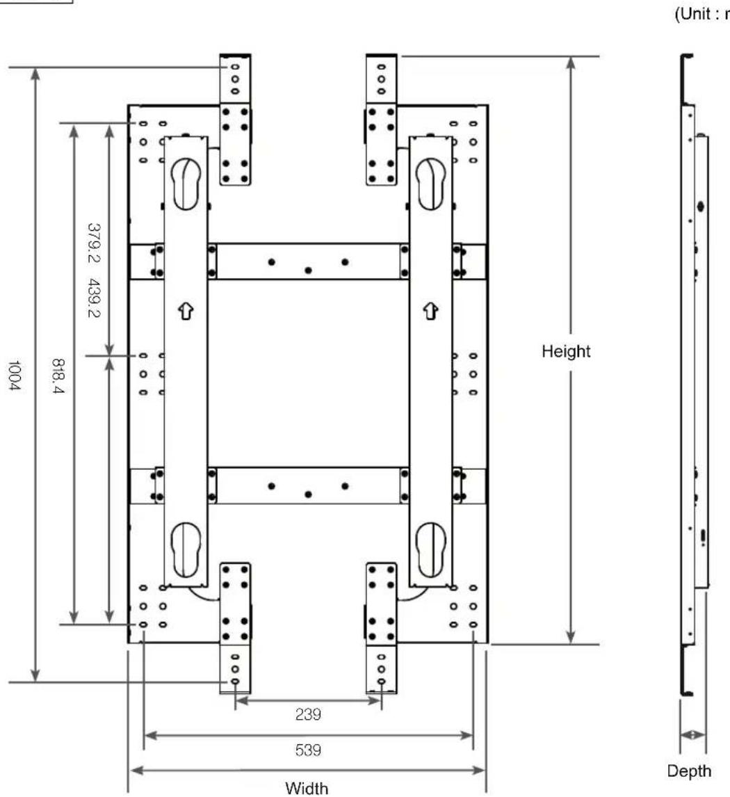
| Product dimensions(width x height x depth) | Product for 47-inch Multi-Vision only 589 mm x 1043.9 mm x 44.5 mm |
| Product for 55-inch Multi-Vision only 683.2 mm x 1212.4 mm x 44.5 mm | |
| Package dimensions(width x height x depth) | 1180 mm x 725 mm x 140 mm |
| Wall Mounting VESA specifications | 600*400 |
| Weight (kgf) 10.9 kgf | |
| Max. tensile load (kgf) 40 kgf | |
| Position adjustment Vertical adjustment in total: approx. 11 mmHorizontal adjustment in total: approx. 85 mm(Product for 55-inch Multi-Vision only approx. 179 mm)Forward: min. approx. 10 mm | |

LG
Life's Good
사용자 설명서
벽걸이 지지대
운반 시 주의 사항

주의

제품 구성
벽걸이 고정 앵커 12개

WM-P640V
여러대의 제품 연결하기
WM-P640V

제품에 멀티비전 장착하기
- WALL MOUNTING BRACKET
- CONTENTS
- 3 SAFETY INSTRUCTIONS
- 5 PRODUCT COMPOSITION
- 6 INSTALLATION GUIDE
- 14 TRANSFORMATION OF PRODUCT
- 16 PRODUCT OPERATION
- 18 PRODUCT SPECIFICATIONS
- SAFETY INSTRUCTIONS
- WARNING
- CAUTION
- PRECAUTION IN INSTALLATION
- PRECAUTIONS WHEN MOUNTING MULTI-VISIONS
- PRECAUTION IN MOVEMENT
- PRODUCT COMPOSITION
- NOTE
- INSTALLATION GUIDE
- PREPARING THE MULTI-VISION TO BE ATTACHED TO PRODUCT
- FIXING THE PRODUCT TO WALL
- CONNECTING MULTIPLE PRODUCTS
- MOUNTING A MULTI-VISION TO THE PRODUCT
- TRANSFORMATION OF PRODUCT
- REASSEMBLY FOR 55-IN MULTI-VISION
- WM-P640V
- PRODUCT OPERATION
- HORIZONTAL ADJUSTMENT
- VERTICAL ADJUSTMENT
- BACK & FORTH ADJUSTMENT
- PRODUCT SPECIFICATIONS
- 사용자 설명서
- 벽걸이 지지대
- 운반 시 주의 사항
- 주의
- 제품 구성
- 여러대의 제품 연결하기
- 제품에 멀티비전 장착하기
Brand : LG
Model : WM-L640V
Category : Television