MMT12HDBWCAM2 - Air Conditioning Mabe - Free user manual and instructions
Find the device manual for free MMT12HDBWCAM2 Mabe in PDF.


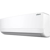
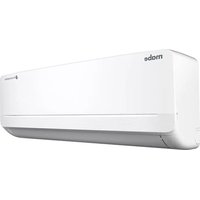
| Type | Split air conditioner (cooling and heating) |
| Model | Mabe MMT12HDBWCAM2 |
| Cooling capacity | 12,000 BTU/h |
| Heating capacity | 12,000 BTU/h (heat pump model) |
| Power supply | 220-230 V ~, 60 Hz |
| Power consumption (cooling) | 1,600 W |
| Current (cooling) | 8 A |
| Refrigerant | R410A, charge 800 g |
| Indoor unit protection rating | IPX0 |
| Outdoor unit protection rating | IPX4 |
| Indoor unit dimensions (approx.) | 800 mm (W) x 290 mm (H) x 210 mm (D) |
| Outdoor unit dimensions (approx.) | 720 mm (W) x 540 mm (H) x 290 mm (D) |
| Indoor unit weight (approx.) | 10 kg |
| Outdoor unit weight (approx.) | 30 kg |
| Maximum pipe length | 15 m |
| Maximum elevation difference | 10 m |
| Remote control | Includes LCD display, batteries (AAA x2) |
| Modes | AUTO, COOL, DRY, FAN, HEAT |
| Special functions | SLEEP, TURBO, QUIET, TIMER (ON/OFF), MY TEMP, ECO, SWING (vertical) |
| Air filter | Washable mesh filter; optional air purifying filter (photocatalyst/bacteria-killing) |
| Safety features | 3-minute restart delay, emergency operation, surge protection recommended |
| Installation requirements | Professional installation; dedicated circuit with breaker; grounding required |
Frequently Asked Questions - MMT12HDBWCAM2 Mabe
User questions about MMT12HDBWCAM2 Mabe
0 question about this device. Answer the ones you know or ask your own.
Ask a new question about this device
Download the instructions for your Air Conditioning in PDF format for free! Find your manual MMT12HDBWCAM2 - Mabe and take your electronic device back in hand. On this page are published all the documents necessary for the use of your device. MMT12HDBWCAM2 by Mabe.
USER MANUAL MMT12HDBWCAM2 Mabe
for the English version, go to page 47
lea este instructivo antes de instalar su aire acondicionado read this manual before installing your new air conditioner
modelos/models
MMI12CABWCA6M8
MMI12HABWCA6M8
MMI12CDBWCA6M8
MMI12HDBWCA6M8
MMI18CDBWCA6M8
MMI18HDBWCA6M8
MMI24CDBWCA6M8
MMI24HDBWCA6M8
MMT12CABWCAM2
MMT12HABWCAM2
MMT12CDBWCAM2
MMT12HDBWCAM2
MMT18CDBWCAM1
MMT18HDBWCAM1
MMT24CDBWCAM1
MMT24HDBWCAM1
MMI12CABWCA6MO
MMI12HABWCA6M0
MMI12CDBWCA6MC8
MMI12HDBWCA6MC8
MMI18CDBWCA6MC8
MMI18HDBWCA6MC8
MMI24CDBWCA6MC8
MMI24HDBWCA6MC8
MMI12CABWCC6M8
MMI12CDBWCC6M8
MMI18CDBWCC6M8
MMI24CDBWCC6M8
MMT12HABWCAMC2
MMT12CABWCAMC2
MMT12HDBWCAMC2
MMT12CDBWCAMC2
MMT18HDBWCAMC1
MMT18CDBWCAMC1
MMT24HDBWCAMC1
MMT24CDBWCAMC1


PM01
0011514388
mabe
bar
| Category | Value | |---|---| | Category 1 | 0.5 | | Category 2 | 0.6 | | Category 3 | 0.7 | | Category 4 | 0.8 | | Category 5 | 0.9 | | Category 6 | 1.0 | | Category 7 | 0.95 | | Category 8 | 0.85 | | Category 9 | 0.75 | | Category 10 | 0.65 |contenido
flowchart
graph TD
    A["1"] --> B["Circle"]
    B --> C["2"]
    C --> D["Power Supply"]
    D --> E["3"]
    E --> F["Lack"]
    F --> G["4"]
    G --> H["Return to Clock"]
    H --> I["Return to Alarm"]
TURBO/QUIET operation
Notas:
natural_image
Cartoon illustration of a character holding a rectangular box next to a large rectangular container (no text or symbols)natural_image
Diagram of a hand pressing down on a rectangular device with a curved arrow indicating motion (no text or symbols)natural_image
Illustration of two children reacting to a bad airlock, one holding a bat and the other standing beside a grid (no text or symbols)natural_image
Two diagrams showing hand positioning of a helmet on a vertical surface, with no text or symbols present.Placa de montaje
natural_image
Three technical diagrams showing mechanical assembly and mounting bracket (no text or symbols)Important Safety Instructions 48
Parts and features 49
Operation instructions .... 51
Remote control 51
Emergency and Test operation 58
Air flow direction adjustment 59
SLEEP function 60
Healthy Airflow 61
Timer On/Off operation 62
TURBO operation 62
Installing the batteries 63
Maintenance 64
WARNINGS 67
Troubleshooting 70
Installation instructions 73
Selection of installation place 73
Installation of indoor and outdoor units 74
Indoor Unit 77
Outdoor Unit 81
Installation checklist and test run 87
Rated electrical specifications 88
welcome
Everything you need to know for the proper operation of your product can be found here and in our web sites.
We invite you to get to know your product, read this manual and get the most out of it.
Important Safety Instructions
- Your own safety is important for us. Please read this information before using your new product.
- Do not use extension cords.
- Do not plug other electric appliances to the same power outlet.
- Hold the connector by the power plug, not by the cord.
- This product is equipped with a "Y" type polarized plug having a built-in grounding wire.
- Do not remove the grounding terminal or use outlet adapters.
- If the power cord is damaged, it must be replaced by the manufacturer, its authorized service agent or by qualified personnel in order to avoid a hazard.
- If voltage variations are usual in your area, have a voltage regulator installed.
- This appliance is not intended for use by persons (including children) having reduced physical, sensory or mental capabilities, or lack of experience and knowledge, unless they have been given supervision or instruction concerning the use of the appliance by a person responsible for their safety.
- Children should be supervised to make sure they do not use the appliance as a toy.
- IMPORTANT: Failure to follow these warnings, will make you entirely responsible for personal injuries or material damages that may occur from using this equipment.
- If the appliance will be connected to a fixed power supply wiring, a surge protector must also be installed and a main power switch and/or fuse rated 1.5 times the maximum current of the unit should be used.
The following conditions are not considered as a normal use of the appliance:
- If it has not been operated in accordance with the provided operation instructions.
- Damages caused by accidents, electrical overloads, voltage fluctuations, using an energy other than the specified, or catastrophes.
- If it has been used with commercial or industrial purposes, or for other than the indicated in the operation instructions.
- If the product has been repaired by unauthorized persons and/or service workshops.
indoor unit

display board B

- Signal receiver hole.
- Ambient temp. display. When receiving the remote control signal, display the set temperature.
- Operation mode indicator (lights up when the compressor is on.)
display board C (on models having only LED indicators)

flowchart
graph TD
    A["1"] --> B["Circle"]
    B --> C["2"]
    C --> D["Power"]
    D --> E["3"]
    E --> F["L"]
    F --> G["4"]
    G --> H["Return"]
    H --> I["Return"]
- Remote control signal receiver. A beep is heard when a signal from the remote control is received.
- Power indicator. Lights up when the unit starts.
- TIMER mode indicator. Lights up when the TIMER operation is selected.
- Operation mode indicator. Lights up when the compressor is on.
display board

display board A

- Signal receiver hole.
- Ambient temp. display. When receiving the remote control signal, display the set temperature.
- COOL display
- HEAT display
- HEALTH display
- DRY display
outdoor unit
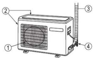
- Outlet
- Inlet
- Connecting piping and electrical wiring
- Drain hose
operation Instructions
remote control
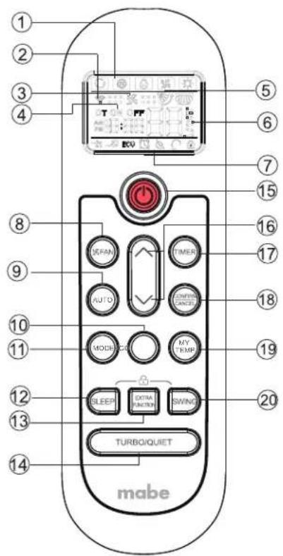
1. Mode display
| Operation Mode | AUTO | COOL | DRY | FAN | HEAT |
| Remote Control |
2. Signal sending display
3. FAN SPEED display

4. TIMER OFF display
TIMER ON display
5. SWING display
6. TEMP display
- Additional functions display
| Operation mode | QUIET | TURBO | ENERGY ECONOMIC | SLEEP | MY TEMP |
| Remote control | ECO |
- FAN SPEED button
- AUTO button
- ECO button
- MODE button
| Operation Mode | COOL | DRY | FAN | HEAT |
| Remote Control |
- SLEEP button
- EXTRA FUNCTION button
- TURBO/QUIET button
- POWER button
- UP/DOWN button
- TIMER button
- CONFIRM/CANCEL button
Function: Setting and cancel to the timer and other additional functions.
- MY TEMP button
- SWING UP/DOWN button
basic operation

- Unit start
Press ON/OFF on the remote controller, unit starts.
- MODE button
It will follow cycle "cooling---dehumidify---air blowing---heating---cooling" (For cooling only model, heating mode is invalid
- Select a temperature setting
^ ∨ nottub ro eht sserP
^ Every time the button is pressed, the temperature setting increases 1 °C, if kept depressed, it will increase rapidly.
√ Every time the pad is pressed, the temperature setting decreases 1 °C, if kept depressed, it will decrease rapidly.
Select a desired temperature.
- Fan function
Press the FAN pad.
Each time the FAN SPEED button is pressed, the fan speed will change as follows:
Remote control:

Air conditioner is running under displayed fan speed.
When FAN is set to AUTO, the air conditioner automatically adjusts the fan speed according to room temperature.
| Operation mode | Remote control Note | |
 | Under the mode of auto opera-AUTO tion, air conditioner will automatically select Cool or Heat operation according to room temperature.When FAN is set to AUTO, the air conditioner automatically adjusts the fan speed according to room temperature. | |
| COOL |  | Cooling only units do not have displays and functions related with heating. |
| DRY |  | In DRY mode, when room temperature becomes lower than temp. setting + 2 °C, unit will run intermittently at LOW speed regardless of FAN setting. |
| HEAT (only on some models) |  | In HEAT mode, warm air will blow out after a short period of the time due to cold-draft prevention function. |
| FAN |  | In FAN operation mode, the unit will not operate in COOL or HEAT mode but only in FAN mode. AUTO is not available in FAN mode. Temperature setting is disabled. When FAN is set to AUTO, the air conditioner automatically adjusts the fan speed according to room temperature. In FAN mode, SLEEP operation is not available. |

Press AUTO then enter auto mode.
Energy saving function, it works under cooling only mode, after enter ECO function, the logo of "ECO" will display on the remote screen.
When the MY TEMP function is activated, the remote control will sense and display the temperature around it in order to achieve the desired temperature.
The distance between the remote control and the indoor unit should be 7 m maximum, without obstacles.
air flow direction adjustment
vertical air flow
Pos. 1: → ↖ → ↖ → ↖ → ↖ → ↖ → ↖ → AUTO Swing Initial State
Pos. 2: No initial state displayed on remote control. The vertical louvers will be fixed on the current position.
CAUTIONS:
- Before adjusting the louvers manually, turn off the unit.
- When humidity is high, condensate water might occur at air outlet if all vertical louvers are adjusted to the right.
- It is advisable not to keep horizontal flap at downward position for a long time in COOL or DRY mode, otherwise, condensate water might occur.
- When restarting after turning the unit OFF with the remote control, the remote will automatically return to the previous set swing position.
SLEEP function
Press the SLEEP button, the remote control will show 📄, and then achieve to the sleep function. Press again the SLEEP pad, the sleep function will be cancelled.
Operation mode
1. In COOL or DRY mode
1 hour after SLEEP mode starts, the temperature will become 1 °C higher than temperature setting. After another hour, the temperature will rise another 1 °C. The unit will run for further 6 hours then stops. Temperature is higher than temperature setting so that room temperature won't be too low for your sleep.

flowchart
graph TD
    A["SLEEP operation starts"] --> B["1 hour"]
    B --> C["1 hour"]
    C --> D["6 hours approx."]
    D --> E["Rises 1 °C"]
    E --> F["Unit stops"]
    style A fill:#f9f,stroke:#333
    style B fill:#ccf,stroke:#333
    style C fill:#cfc,stroke:#333
    style D fill:#fcc,stroke:#333
    style E fill:#ffc,stroke:#333
    style F fill:#cff,stroke:#333
In COOL and DRY modes
2. In HEAT mode (only on some models)
1 hour after SLEEP mode starts, temperature will become 2 °C lower than temperature setting. After another 1 hour, the temperature decreases by 2 °C further. After another 3 hours, temperature rises by 1 °C further. The unit will run for another 3 hours then stops. Temperature is lower than temperature setting so that room temperature won't be too high for your sleep.
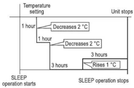
flowchart
graph TD
    A["Temperature setting"] --> B["1 hour"]
    B --> C["Decreases 2 °C"]
    B --> D["1 hour"]
    D --> E["Decreases 2 °C"]
    D --> F["3 hours"]
    F --> G["Rises 1 °C"]
    G --> H["3 hours"]
    H --> I["SLEEP operation starts"]
    style A fill:#f9f,stroke:#333
    style I fill:#ccf,stroke:#333
In HEAT mode
3. In AUTO mode
The unit operates in corresponding sleep mode adapted to the automatically selected operation mode.
4. In FAN mode
The SLEEP function will not be available under the FAN mode.
- When quiet sleeping function is set to 8 hours the quiet sleeping time can not be adjusted. When TIMER function is set, the quiet sleeping function can't be set up. After the sleeping function is set up, if user resets TIMER function, the sleeping function will be cancelled; the machine will be in the state of timing-on, if the two modes are set up at the same time, either of their operation time is ended first, the unit will stop automatically, and the other mode will be cancelled.
Note:
- When TIMER function is set, the sleeping function can't be set up. After the sleeping function is set up, if user resets TIMER function, the sleeping function will be cancelled; the machine will be in the state of timing-on.
- Power failure resume: Press the sleep pad ten times within five seconds and enter function after hearing four sounds. And press the sleep pad ten times within five seconds and leave this function after hearing two sounds.
- Power failure resume function: If the unit is started for the first time, the compressor will not start running unless 3 minutes have elapsed. When the power resumes after power failure, the unit will run automatically, and 3 minutes later the compressor starts running.
timer operation
- After unit starts, select the desired operation mode.
-
Press the TIMER button to change TIMER mode. When pressing TIMER button, the display will show "ON 0.5". After 10 seconds the time display will be blank.
When pressing TIMER button, the display will show "OFF 0.5". After 10 seconds the time display will be blank. Then select the desired TIMER mode, "ON" or "OFF" will flash. -
Press TIMER button to set time.
Each time you press the button, the time setting will be increased by 0.5 hours until reaching 12 hours, then each press will increase the time by 1 hour until reaching 24 hours.
- Confirm TIMER setting. After setting the desired time press the CONFIRM/CANCEL button to CONFIRM your selection "ON" or "OFF" will stop flashing.
To cancel the TIMER
Press the CONFIRM/CANCEL button again. The set TIME will be deleted.
After replacing batteries or a power failure, the time should be reset.
According to the time setting sequence of TIMER ON or TIMER OFF, either Start-Stop or Stop-Start can be achieved.
TURBO/QUIET operation
When you need rapid heating or cooling, you can use this function.
Press the TURBO/QUIET pad, the remote control will show ↗, and then the unit starts the TURBO function.
Press the TURBO/QUIET pad, the remote control will show →, and then the unit starts the QUIET function.
To turn off TURBO, press again the TURBO pad.
Note: During TURBO operation, in rapid cool mode, the room could show uneven temperature distribution.
Indoor Unit LED Display
Press the TURBO/QUIET pad for 3 seconds to turn the indoor unit led display on or off.
emergency and test operation
emergency operation
- Use this operation only when the remote control is defective or lost, and with function of Emergency running air conditioner can run automatically for a while.
- When the emergency operation switch is pressed, a "Pi" sound is heard once, which means the start of this operation.

- When POWER switch is turned on for the first time and emergency operation starts, the unit will run automatically in the following mode:
- It is not possible to change the temperature setting or fan speed setting. It is also not possible to operate the timer or the DRY mode.
| Room temperature | Designated temperature | TIMER mode Fan Speed | Operation mode |
Above 23 °C COOLING26 °C No AUTOMATIC
test operation
- Test operation switch is the same as emergency switch.
- Use this switch in the test operation when the room temperature is below 16^ , do not use it in the normal operation.
- Continue to press the test operation switch for more than 5 seconds. After you hear two "Beeps", release your finger from the switch: the cooling operation starts with the air flow speed at "Hi".

- Under this operation mode, the fan motor of the indoor unit will run at HIGH speed.
installing the batteries
- Remove the battery cover.
- Insert 2 "AAA" batteries as illustrated noting battery polarity.
- Reinstall the battery cover.

Notes:
- The distance from the remote control to the receiver should be less than 7 meters with no obstructions.
- If the remote control display is weak or the operating distance has diminished, the batteries may need to be replaced.
- Remote control malfunctions can sometimes be corrected by removing the batteries from the remote for a few minutes and then reinstalling them.
- Remove the batteries from the remote control if the unit will not be in use for an extended period of time.
- If any segments of the display remain active after battery removal, press the reset button.
maintenance
Set a proper room temperature. Do not block air inlets and outlets.

Close doors and windows during operation.

During cooling operation, avoid direct sunlight using curtains or blinds.
Use the timer effectively.
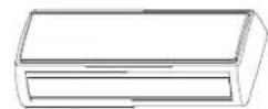

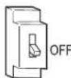
If the unit is not to be used for a long time, turn off the power supply main switch.
Use the louvers effectively.

remote control
Do not use water, wipe the remote control with a dry cloth. Do not use glass cleaners or a chemical cloth.

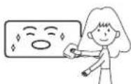
indoor unit body
Wipe the air conditioner using a soft and dry cloth. For serious stains, use a neutral detergent diluted with water. Wring the water out of the cloth before wiping. Then wipe off the detergent completely.
do not use the following for cleaning
Gasoline, benzine, thinner or cleanser may damage the finish of the unit.

Hot water over 40 °C (104 °F) may cause discoloration or deformation.

air filter cleaning
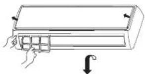
- Open the inlet grille by pulling it upwards.
- Remove the filter. Push up the filter's center tab slightly until it is released from the stopper, and remove the filter downward.
natural_image
Illustration of a hand placing a component into a rectangular device with a downward arrow indicating rotation (no text or symbols)-
Clean the filter. Use a vacuum cleaner to remove dust, or wash the filter with water. After washing, dry the filter completely in the shade.
-
Attach the filter. Attach the filter correctly so that the "FRONT" indication is facing to the front. Make sure that the filter is completely fixed behind the stopper. If the right and left filters are not attached correctly, that may cause defects.
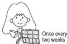
- Close the inlet grille.
replacing the air purifying filter
NOTE: The air purifying filter is an optional part.
- Open the inlet grille. Prop up the inlet grille by using a small device named grille-support which is located in the right side of the indoor unit.

- Detach the standard air filter. Slide the knob slightly upward to release the filter, then remove it.
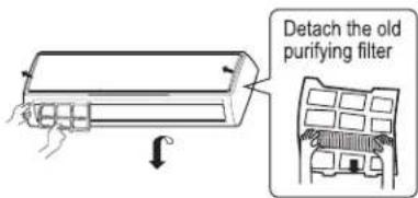
- Attach the air purifying filter. Place air purifying filter into the right and left filter frames.

- Attach the standard air filter. (Necessary installation).
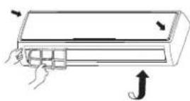
ATTENTION: The white side of the photocatalyst air purifying filter faces outside, and the black side faces the unit. The green side of the bacteria-killing medium air and the white side faces the unit.
- Securely close the inlet grille.
Notes:
- The photocatalyst air purifying filter will be solarized in fixed time. In normal family, it will be solarized every 6 months.
- The bacteria-killing medium air purifying filter will be used for a long time, no need for replacement. But in the period of using them, you should remove the dust frequently using a vacuum cleaner or flapping them lightly, otherwise its performance will be affected.
- Please keep the bacteria-killing medium air purifying filter under cool and dry conditions and avoid long time directly sunshine when you stop using it, or its ability of sterilization will be reduced.
WARNINGS
WARNINGS:
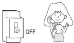
- CALL SALES/SERVICE DEPARTMENT FOR THE INSTALLATION.
- DO NOT ATTEMPT TO INSTALL THE AIR CONDITIONER FOR YOURSELF BECAUSE AN IMPROPER INSTALLATION MAY CAUSE ELECTRIC SHOCK, FIRE, WATER LEAKAGE.
- If an abnormality is found such as burnt-smell, immediately stop the operation pad and contact sales department.
- Check proper installation of the drainage securely.

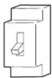
- Use an exclusive power source with a circuit breaker.
- Connect power supply cord to the outlet completely. Use the proper voltage.

- Do not use an extension power supply cord or connected half-way.
- Do not install in a place where there is a possibility of inflammable gas leakage around the unit.
- Do not get the unit to be exposed to vapor or oil steam.
- Do not use power supply cord in a bundle.

- Do not try to repair or reconstruct the system by yourself.

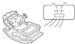
- Do not direct the air flow directly at people, especially at infants or the aged.
• Take care not to damage the power supply cord.

- Connect the grounding cable.

- Do not insert objects into the air inlet or outlet.

natural_image
Illustration of two children reacting to a fire incident, one holding a baton and the other standing beside a fire pit (no text or symbols)- Do not start or stop the operation by disconnecting the power supply cord and so on.

CAUTION
- Do not use for the purpose of storage of food, art work, precise equipment, breeding, or cultivation.

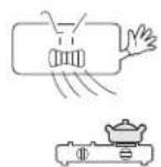
- Do not install the unit near a fireplace or other heating appliance.
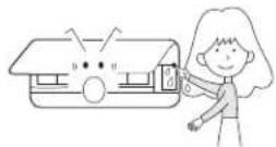
- Do not operate the switch with wet hands.
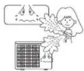
- Do not pour water onto the unit for cleaning.
- Check good condition of the installation stand.

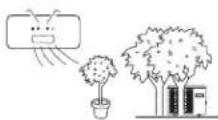
- Do not place animals or plants in the direct path of the air flow.
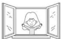
• Take fresh air occasionally especially when gas appliance is running at the same time.
- Do not place any objects on or climb on the unit.

- Do not place flower vase or water containers on the top of the unit.

troubleshooting
Before calling for service, check the following:
Problem Possible cause and points to check
The system does not restart immediately. | After stopping the unit, it won't restart immediately until 3 minutes have elapsed to protect the system.When the electric plug is pulled out and reinserted, the protection circuit will work for 3 minutes to protect the air conditioner. |
| Noise • During unit operation or at stop, a swishingor gurgling noise may be heard. At first 2-3 minutes after unit start, this noise is more noticeable. (This noise is generated by refrigerant flowing in the system.)During unit operation, a cracking noise may be heard. This noise is generated by the case expanding or shrinking because of temperature changes.Should there be a big noise from air flow in unit operation, air filter may be too dirty. | |
| Bad odor • This is because the system circulates odorsfrom the interior air such as the odor of furniture, paint, cigarettes. | |
Mist or steam are blown out | During COOL or DRY operation, indoor unit may blow out mist. This is due to the sudden cooling of indoor air. |
| In dry mode, fan speed can't be changed. | In DRY mode, when room temperature becomes lower than temperature setting +2 °C, unit will run intermittently at LOW speed regardless of FAN setting. |
Problem Possible cause and points to check
Unit won't start. • Is power plug inserted?
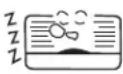
• Is there a power failure?
• Is fuse blown out?
Poor cooling. • Is the air filter dirty? Normally it should be cleaned every 15 days.

- Are there any obstacles before inlets and outlets?
• Is temperature set correctly?
- Are there some doors or windows left open?
- Is there any direct sunlight through the window during the cooling operation? (Use curtains).
- Are there too much heat sources or too many people in the room during cooling operation?
CAUTIONS
The machine is adaptive in following situation
• Applicable ambient temperature range:
For T1
| Cooling | Indoor unit | Maximum: D.B./W.B. Minimum: D.B./W.B. | 89,6 °F/73,4 °F 64,4 °F/57,2 °F | 32 °C/23 °C 18 °C/14 °C |
| Outdoor unit | Maximum: D.B. Minimum: D.B. | 109,4 °F/78,8 °F 64,4 °F | 43 °C/26 °C 18 °C | |
| Heating | Indoor unit | Maximum: D.B. Minimum: D.B. | 80,6 °F/59 °F 59 °F | 27 °C/15 °C 15 °C |
| Outdoor unit | Maximum: D.B./W.B. Minimum: D.B./W.B. | 75,2 °F/64,4 °F 19,4 °F/17,6 °F | 24 °C/18 °C -7 °C/-8 °C |
T3: Temperature range of air conditioner -7 °C to 52 °C
- If the supply cord is damaged, it must be replaced by the manufacturer or its service agent or a similar qualified person. The type of connecting wire is H05RN-F or H07RN-F
- If the fuse on PC board is broken please change it with a fuse type T. 3.15A/250V. If the fuse of outdoor unit on PC board is broken, please change it with the type of T. 25A/250V.
- The distance between the indoor unit and the floor should be more than 2 m.
- The wiring method should be in line with the local wiring standard.
- The used batteries should be disposed of properly.
- The appliance is not intended to use by young children or infirm persons without supervision.
- Young children should be supervised to ensure that they do not play with the appliance.
- The appliance must be installed on a strong enough support.
- The wiring diagram is attached inside the machine.
installation instructions
preparation
Necessary tools for installation
- Driver
- Nipper
- Hacksaw
- Hole core drill
-
Spanner (17, 19 and 26 mm)
• Gas leakage detector or soap and water solution -
Torque wrench (17 mm, 22 mm, 26 mm)
- Pipe cutter
- Flaring tool
- Knife
- Measuring tape
- Reamer
power source
- Before inserting the power plug into the receptacle, check the voltage without fail. The power source must be the same as the corresponding name plate.
• Install an exclusive branch circuit for the power. - A receptacle must be set up in a distance where the power cable can be reached. Do not extend the cable by cutting it.
Important: The appliance must be installed in accordance with the national regulations for electrical installations.
selection of installation location
Indoor Unit
- Place, robust not causing vibration, where the body can be supported sufficiently.
- Place not affected by heat or steam generated in the vicinity, where inlets and outlets of the unit are not disturbed.
- Place possible to drain easily, where piping can be connected with the outdoor unit.
- Place where cold air can be spread in a room entirely.
- Place where the distance of more than 1 m from television sets, radios, wireless apparatuses and fluorescent lamps can be left.
- In the case of fixing the remote control on a wall, place where the indoor unit can receive signals when the fluorescent lamps in the room are lightened.
Outdoor Unit
- Place which is less affected by rain or direct sunlight, and is sufficiently ventilated.
- Place sturdy enough to bear the unit, where vibration and noise are not increased.
- Place where discharged wind and noise do not cause a nuisance to the neighbors.
- Place where a distance marked is available as illustrated in the above figure.
installation of indoor and outdoor units
These models adopt HFC free refrigerant R410A.

optional parts for piping
A. Nonadhesive tape
B. Adhesive tape
C. Saddle (L. S) with screws
D. Connecting electric cable for indoor and outdoor
E. Drain hose
F. Heating insulating material
G. Piping hole cover
- Please refer to the actual product purchased, the above picture is just for reference.
- Read this manual before installation.
- Explain sufficiently the operating means to the user according to this manual.
accessories
| Reference | Part | Quantity | |
| 1 | Remote control | 1 | |
| 2 | Dry battery R-03 |  | 2 |
| 3 | Mounting plate |  | 1 |
| 4 | Drain hose | 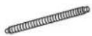 | 1 |
| 5 | Stail nail, cement | ∅4X12 | 2 |
| 6 |  ∅4X25 Screw ∅4X25 Screw |  Plastic anchor Plastic anchor | 5 |
| 7 | Drain elbow |  | 1 |
| 8 | Cover |  | 1 |
| 9 | Cushion |  | 4 |
| 10 | Pipe support plate |  | 1 |
| 11 | Connecting cable |  | 1 |
Note: 1. COOLING only units do not include the drain elbow. 2. Some units do not include the stall nail.


Outdoor unit floor fixing dimensions. Units in mm
For 18 000 BTU/h and some 12 000 BTU/h system

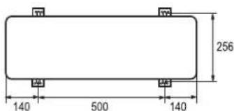
Outdoor unit floor fixing dimensions. Units in mm
For some 12 000 BTU/h


Outdoor unit floor fixing dimensions.
Units in mm
For some 24 000 BTU/h
selection of pipes
| some 12000 BTU systems | 18000,24000 and some 12000 BTU systems | |
| Liquid pipe (diameter) | ||
| Copper-Aluminum | 6,35 mm (1/4") | 6,35 mm (1/4") |
| Copper Tube | 6 mm 6 mm | |
| Gas pipe (diameter) | ||
| Copper-Aluminum | 9,52 mm (3/8") | 12,7 mm (1/2") |
| Copper Tube | 9 mm 12 mm | |
NOTE: The thickness of the pipe must be 0.8 mm at least.
In order to know the pipe diameter of the acquired model, check the model label located on one side of the unit.
indoor unit
- Fitting of the mounting plate and positioning of the wall hole.
When the mounting plate is first fixed
-
Carry out based on the neighboring pillars or lintels, a proper leveling for the plate to be fixed against the wall, then temporarily fasten the plate with one steel nail.
-
Check again the proper level of the plate by hanging a thread with a weight from the central top of the plate, then fasten securely the plate with the attachment steel nail.
-
Find the wall hole location "A" using a measuring tape.

For 12 000 BTU/h systems
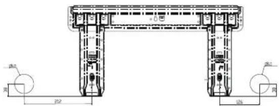
For some 18 000 BTU/h systems
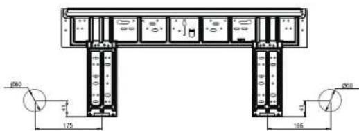
For some 18 000 BTU/h and some 24 000 BTU/h systems

For some 24 000 BTU/h systems
When the mounting plate is fixed side bar and lintel
-
Fix to side bar and lintel a mounting bar, which is separately sold, and then fasten the plate to the fixed mounting bar.
-
Refer to the previous section, "When the mounting plate is first fixed" for the position of wall hole.
-
Make a hole on the wall and fit the piping hole cover.
-
Make a hole of 60 mm in diameter, slightly descending to outside the wall.
• Install piping hole cover and seal it off with putty after installation.

- Routing the pipes
Rear piping
- Draw pipes and the drain hose, then fasten them with the adhesive tape.
Left-Left-rear piping
- In case of left side piping, cutaway with a nipper the lid for left piping.
-
In case of left-rear piping, bend the pipes according to the piping direction to the mark of hole for left-rear piping which is marked on heat insulation materials.
-
Insert the drain hose into the dent of heat insulation materials of indoor unit.
- Insert the indoor/outdoor electric cable from backside of indoor unit, and pull it out on the front side, then connect them.
- Coat the flaring seal face with refrigerant oil and connect pipes. Cover the connection part with heat insulation materials closely, and make sure fixing with adhesive tape.


- Indoor/outdoor electric cable and drain hose must be bound with refrigerant piping by protecting tape.
Other direction piping
- Cut with a nipper, the lid for piping according to the piping direction and then bend the pipe according to the position of wall hole. When bending, be careful not to crash pipes.
- Connect beforehand the indoor/outdoor electric cable, and then pull out the connected to the heat insulation of connecting part specially.
fixing the indoor unit body
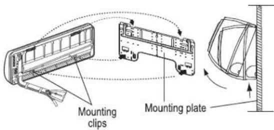
- Hang surely the unit body onto the upper notches of the mounting plate. Move the body from side to side to verify its secure fixing.
- In order to fix the body onto the mounting plate, hold up the body aslant from the underside and then put it down perpendicularly.
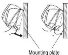
unloading of indoor unit body
- When you unload the indoor unit, please use your hand to arise the body to leave agraffe, then lift the bottom of the body outward slightly and lift the unit aslant until it leaves the mounting plate.
connecting the indoor/outdoor electric cable
- Remove terminal cover at right bottom corner of indoor unit, then take off wiring cover by removing its screws.
- Insert from outside the room cable into left side of the wall hole, in which the pipe has already existed.
- Pull out the cable on the front side, and connect the cable making a loop.
- Insert the cable from the back side of the unit, then pull it out on the front side.
- Loosen the screws and insert the cable ends fully into terminal block, then tighten the screws.
- Pull the cable slightly to make sure the cables have been properly inserted and tightened.
- After the cable connection, never fail to fasten the connected cable with the wiring cover.
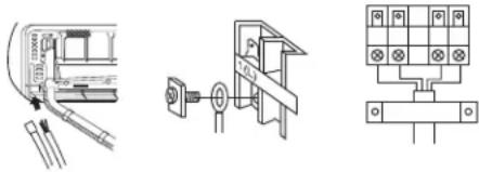
natural_image
Three technical diagrams showing mechanical assembly, a switch mechanism, and a grid-based circuit (no text or symbols)Note: When connecting the cable, confirm the terminal number of indoor and outdoor units carefully. If wiring is not correct, proper operation can not be carried out and will cause defect.
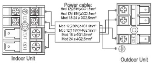
For 9 000 BTU/h, 12 000 BTU/h, 18 000 BTU/h and 24 000 BTU/h systems
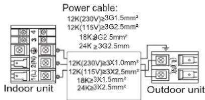
In 12 000 BTU/h, 18 000 BTU/h and some 24 000 BTU/h cooling only systems

In 12 000 BTU/h, 18 000 BTU/h and some 24 000 BTU/h heating systems

In some 24 000 BTU/h cooling only systems
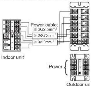
In some 24 000 BTU/h heating systems
NOTE: Consult the electrical wiring diagram for each particular model.
- If the supply cord is damaged, it must be replaced by the manufacturer or its service agent or a similar qualified person. The type of connecting wire is H05RN-F or 245 IEC57.
- If the fuse on PC board is broken, please change it with the type of T. 3.15 A/250 V.
- The wiring method should be in line with the local wiring standard.
• After installation, the power plug should be easily reached. - A breaker should be incorporated into fixed wiring. The breaker should be all—pole switch and the distance between its two contacts should be not less than 3 mm.
outdoor unit
Install according to drawing for the installation of indoor and outdoor units.
connection of pipes
- To bend a pipe, give the roundness as large as possible not to crush the pipe, and the bending radius should be 30 to 40mm or longer.
- Connecting the pipe of gas side first makes working easier.
- The connection pipe must be specialized for R410A.
Half union
Flare nut


Wrench
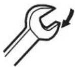
Torque wrench
IMPORTANT: Forced fastening without careful centering may damage the threads and cause a leakage of gas.
| Pipe diameter (Ø) | Fastening torque |
| Liquid side 6,35 mm (1/4") | 18 N·m |
| Liquid/Gas 9,52 mm (3/8") | 42 N·m |
| Gas side 12,7 mm (1/2") | 55 N·m |
| Gas side 15,9 mm (5/8") | 60 N·m |
Be careful that matters, such as wastes of sands, etc. shall not enter the pipe.
The standard pipe length is 5 m, if it is over 7 m, the function of the unit will be affected. If the pipe has to be lengthened, the refrigerant should be charged according to 20 g/m. But the charge of refrigerant must be conducted by professional air conditioner engineer. Before adding additional refrigerant, perform air purging from the refrigerant pipes and indoor unit using a vacuum pump, then charge additional refrigerant.
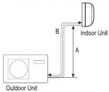
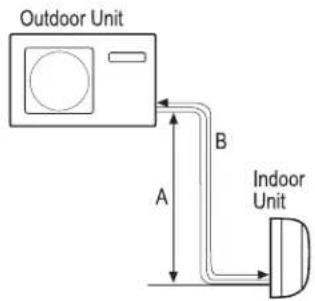
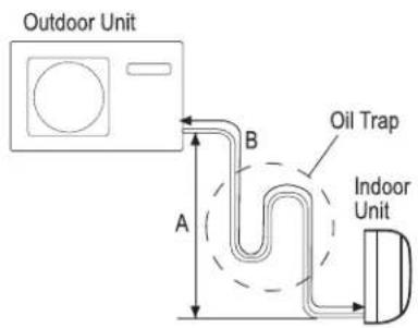
• Maximum elevation: (A) max = 10 m
- In case the elevation (A) is more than 5 m, oil trap should be installed every 5 to 7 m
• Maximum length: (B) max = 15 m
- In case the pipe length B is more than 7 m, the refrigerant should be charged, according to 20 g/m.
connection
- Use the same method on indoor unit. Loosen the screws on terminal block and insert the plugs fully into terminal block, then tighten the screws.
- Insert the cable according to terminal number in the same manner as the indoor unit.
- If wiring is not correct, proper operation can not be carried out and controller may be damaged.
• Fix the cable with a clamp.
attaching a drain elbow
- If a drain elbow is used, please attach it as figure. (Note: Only on heat pump units.)
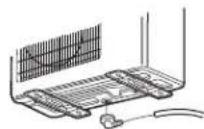
using a vacuum cleaner as purging method
- Detach the service port's cap of 3-way valve, the valve rod's cap for 2-way valve and 3-way's, connect the service port into the projection of charge hose (low) for gauge manifold. Then connect the projection of charge hose (center) for gauge manifold into vacuum pump.
- Open the handle at low in gauge manifold, operate vacuum pump. If the scale moves of gauge (low) reach vacuum condition in a moment, check 1 again.
- Vacuum for over 15 minutes and check the level gauge which should read -0,1 MPa (76 cm Hg) at low pressure side. After the completion of vacuum, close the handle "LO" in gauge manifold and stop the operation of the vacuum pump. Check condition of the scale and hold it for 1-2 min. If the scale moves back in spite of tightening, make flaring work again, the return to the beginning of 3.
- Open the valve rod for the 2-way valve to an angle of anticlockwise 90 degrees. After 6 seconds, close the 2-way valve and make the inspection of gas leakage.
- No gas leakage?
In case-of gas leakage, tighten parts of pipe. If leakage stops, then proceed to step 6.
If it does not stop, discharge whole refrigerants from the service port. After flaring work again and vacuum, fill up prescribed refrigerant from the gas cylinder. -
Detach the charge hose from the service port, open 2-way valve and 3-way. Turn the valve rod anticlockwise until hitting lightly.
-
To prevent gas leakage, turn the service port's cap. The valve rod's cap for 2-way valve and 3 way's a little more than the point where the torque increases suddenly.
- After attaching each cap, check for gas leakage around the caps.
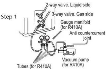

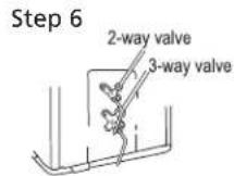
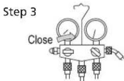
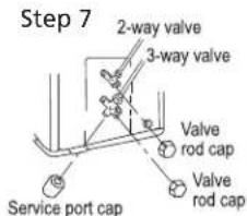


CAUTION
- If the refrigerant of the air conditioner leaks, it is necessary to discharge all the refrigerant. Vacuum first, then charge the liquid refrigerant into air conditioner according to the amount marked on the name plate.
- Please do not let other cooling medium except the specified one (R410A) or air enter into the cooling circulation system. Otherwise there will be abnormal high pressure in the system to make it crack and lead to personal injuries.
power source
- The power source must be exclusively used for air conditioner (over 10 A).
- In case of installing an air conditioner in a moist place, please install a ground leakage breaker.
- For installation in other places, use a circuit breaker as far as possible.
cutting and flaring work of piping
- Pipe cutting is carried out with a pipe cutter and burs must be removed.


natural_image
Illustration of hands using a tool to cut a funnel into a container (no text or symbols)- Flare pipe.

1. Cut pipe

2. Remove burs

3. Insert flare nut
| Correct | Incorrect | ||
| Lean | Damagedflare | Cracking | |
| Correct | Incorrect | |
| Partialflare | Flare too large | |
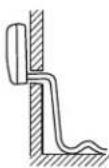
drainage
• Install the drain hose so as to be downward slope without fail.
- Do not install the drainage as shown below.
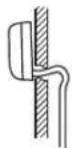
Too high midway

End immersed in water
Waves

Clearance with floor is too small

Bad odor from ditch
- Pour water in the drain pan of the indoor unit and confirm that drainage is carried out securely outdoors.
- In case that the attached drain hose is in a room, please apply heat insulation to it without fail.
refrigerant charge label
Contains fluorinated greenhouse gases covered by the Kyoto Protocol ____ A


This product contains fluorinated greenhouse gases covered by the Kyoto Protocol. Do not vent into the atmosphere.
Refrigerant type: R410A
GWP* value: 2088
GWP = global warming potential
Please fill in with indelible ink
1: The factory refrigerant charge.
2: The additional refrigerant amount charged in the field and
1+2: the total refrigerant charge
The filled out label must be adhered in the proximity of the product charging port (e.g. onto the inside of the stop valve cover).
A. Contains fluorinated greenhouse gases covered by the Kyoto Protocol.
B. Factory refrigerant charge of the product: see unit name plate
C. Additional refrigerant amount charged in the field.
D. Total refrigerant charge.
E. Outdoor unit.
F. Refrigerant cylinder and manifold for charging.
installation check and test run
□ Gas leak from pipe connections?
□ Heat insulation of pipe connecting?
□ Are the connecting wirings of indoor and outdoor firmly inserted to the terminal block?
□ Is the connecting wiring of indoor and outdoor firmly fixed?
□ Is drainage securely carried out?
□ Is the ground line securely connected?
□ Is the indoor unit securely fixed?
□ Is power source voltage abided by the code?
□ Is there any noise?
□ Is the lamp normally lighting?
□ Are cooling and heating performed normally?
□ Is the operation of room temperature regulator normal?
ratedelectricalspecifications
| Model | MMI12CABWCC6M8MMI12CABWCA6MC8MMI12CABWCA6M8 | MMI12HABWCA6MC8MMI12HABWCA6M8 |
| Supply voltage | 115 V ~ | 115 V ~ |
| Power consumption | 1 200 W | 1 200 W |
| Current consumption | 10,5 A | 10,5 A |
| Frequency | 60 Hz | 60 Hz |
| Capacity | 12 331 BTU/h | 12 331 BTU/h |
| Protection rating outdoor unit | IPX4 | IPX4 |
| Protection rating indoor unit | IPX0 | IPX0 |
| Refrigerant/Charge | R410A/500 g | R410A/680 g |
MMI12CDBWCC6M8
MMI12CDBWCA6MC8 MMI12HDBWCA6MC8
MMI12CDBWCA6M8 MMI12HDBWCA6M8
| Model | MMI12CDBWCA6M8 | MMI12HDBWCA6M |
| Supply voltage | 220 - 230 V ~ | 220 - 230 V ~ |
| Power consumption | 1 500 W | 1 500 W |
| Current consumption | 6,5 A | 6,5 A |
| Frequency | 60 Hz | 60 Hz |
| Capacity | 11 872 BTU/h | 11 872 BTU/h |
| Protection rating outdoor unit | IPX4 | IPX4 |
| Protection rating indoor unit | IPX0 | IPX0 |
| Refrigerant/Charge | R410A/500 g | R410A/680 g |
MMI18CDBWCC6M8
MMI18CDBWCA6MC8 MMI18HDBWCA6MC8
MMI18CDBWCA6M8 MMI18HDBWCA6M8
| Supply voltage | 220 - 230 V ~ | 220 - 230 V ~ |
| Power consumption | 1950 W | 1950 W |
| Current consumption | 8 A | 8 A |
| Frequency | 60 Hz | 60 Hz |
| Capacity | 17855 BTU/h | 17855 BTU/h |
| Protection rating outdoor unit | IPX4 | IPX4 |
| Protection rating indoor unit | IPX0 | IPX0 |
| Refrigerant/Charge | R410A/1080 g | R410A/1080 g |
MMI24CDBWCC6M8
MMI24CDBWCA6MC8 MMI24HDBWCA6MC8
MMI24CDBWCA6M8 MMI24HDBWCA6M8
| Model | MMI24CDBWCA6M8 | MMI24HDBWCA6M |
| Supply voltage | 220 - 230 V ~ | 220 - 230 V ~ |
| Power consumption | 2 500 W | 2 500 W |
| Current consumption | 11,5 A | 11,5 A |
| Frequency | 60 Hz | 60 Hz |
| Capacity | 23 138 BTU/h | 23 138 BTU/h |
| Protection rating outdoor unit | IPX4 | IPX4 |
| Protection rating indoor unit | IPX0 | IPX0 |
| Refrigerant/Charge | R410A/1 300 g | R410A/1 300 g |
| Model | MMT12CABWCAMC2MMT12CABWCAM2 | MMT12HABWCAMC2MMT12HABWCAM2 |
| Supply voltage | 115 V ~ | 115 V ~ |
| Power consumption | 1 350 W | 1 350 W |
| Current consumption | 13 A | 13 A |
| Frequency | 60 Hz | 60 Hz |
| Capacity | 12 000 BTU/h | 12 000 BTU/h |
| Protection rating outdoor unit | IPX4 | IPX4 |
| Protection rating indoor unit | IPX0 | IPX0 |
| Refrigerant/Charge | R410A/800 g | R410A/800 g |
| Model | MMT12CDBWCAMC2MMT12CDBWCAM2 | MMT12HDBWCAMC2MMT12HDBWCAM2 |
| Supply voltage | 220 - 230 V ~ | 220 - 230 V ~ |
| Power consumption | 1 600 W | 1 600 W |
| Current consumption | 8 A | 8 A |
| Frequency | 60 Hz | 60 Hz |
| Capacity | 12 000 BTU/h | 12 000 BTU/h |
| Protection rating outdoor unit | IPX4 | IPX4 |
| Protection rating indoor unit | IPX0 | IPX0 |
| Refrigerant/Charge | R410A/800 g | R410A/800 g |
| Model | MMT18CDBWCAMC1MMT18CDBWCAM1 | MMT18HDBWCAMC1MMT18HDBWCAM1 |
| Supply voltage | 220 - 230 V ~ | 220 - 230 V ~ |
| Power consumption | 1 900 W | 1 900 W |
| Current consumption | 9A | 9A |
| Frequency | 60 Hz | 60 Hz |
| Capacity | 18 000 BTU/h | 18 000 BTU/h |
| Protection rating outdoor unit | IPX4 | IPX4 |
| Protection rating indoor unit | IPX0 | IPX0 |
| Refrigerant/Charge | R410A/1 320g | R410A/1 320 g |
| Model | MMT24CDBWCAMC1MMT24CDBWCAM1 | MMT24HDBWCAMC1MMT24HDBWCAM1 |
| Supply voltage | 220 - 230 V ~ | 220 - 230 V ~ |
| Power consumption | 2 400 W | 2 400 W |
| Current consumption | 12 A | 12 A |
| Frequency | 60 Hz | 60 Hz |
| Capacity | 22 000 BTU/h | 22 000 BTU/h |
| Protection rating outdoor unit | IPX4 | IPX4 |
| Protection rating indoor unit | IPX0 | IPX0 |
| Refrigerant/Charge | R410A/1 650g | R410A/1 650 g |
| Model | MMT24CDBWCAM8 | MMT24HDBWCAM8 |
| Supply voltage | 220 - 230 V ~ | 220 - 230 V ~ |
| Power consumption | 2 550 W | 2 550 W |
| Current consumption | 12,3 A | 12,3 A |
| Frequency | 60 Hz | 60 Hz |
| Capacity | 24 000 BTU/h | 24 000 BTU/h |
| Protection rating outdoor unit | IPX4 | IPX4 |
| Protection rating indoor unit | IPX0 | IPX0 |
| Refrigerant/Charge | R410A/1 700 g | R410A/1 770 g |
| Model | MMT24CDBSCAM8 | MMT24HDBSCAM8 |
| Supply voltage | 220 - 230 V ~ | 220 - 230 V ~ |
| Power consumption | 2 550 W | 2 550 W |
| Current consumption | 12,3 A | 12,3 A |
| Frequency | 60 Hz | 60 Hz |
| Capacity | 24 000 BTU/h | 24 000 BTU/h |
| Protection rating outdoor unit | IPX4 | IPX4 |
| Protection rating indoor unit | IPX0 | IPX0 |
| Refrigerant/Charge | R410A/1 700 g | R410A/1 770 g |

bar
| Category | Value | |---|---| | notas/notes | 85 | | Dark Grey Square | 10 | | Dark Grey Square | 12 | | Dark Grey Square | 14 | | Dark Grey Square | 16 | | Dark Grey Square | 18 |Chile: 123.0020.3143
Santiago de Chile: 2618.8346 www.serviciomabe.cl
Colombia: 01.800.518.3227
Bogotá: 508.7373 — Cali: 620.7363 anquilla: 322.5220 — Medellin: 590.5770 www.serviciomabe.com.co
Ecuador: 1.800.00.0690 www.mabe.com.ec
Perú: 0800.78.188 Lima: 706.2952
www.mabe.com.pe
República Bolivariana de Venezuela: 0800.136.2631
Caracas: 212.335.7605 www.mabe.com.ve
natural_image
Abstract geometric pattern with vertical gray bars and horizontal lines, no text or symbols present
natural_image
Abstract geometric pattern with vertical gray bars and horizontal lines, no text or symbols present
natural_image
Abstract geometric pattern with vertical gray bars and horizontal lines, no text or symbols present
natural_image
Blank gray rectangle with corner alignment markers (no text or symbols)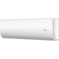
- for the English version, go to page 47
- contenido
- TURBO/QUIET operation
- Notas:
- welcome
- Important Safety Instructions
- indoor unit
- display board B
- display board C (on models having only LED indicators)
- operation Instructions
- remote control
- Mode display
- Signal sending display
- FAN SPEED display
- TIMER OFF display
- SWING display
- TEMP display
- CAUTIONS:
- SLEEP function
- Operation mode
- In COOL or DRY mode
- In HEAT mode (only on some models)
- In AUTO mode
- In FAN mode
- Note:
- timer operation
- To cancel the TIMER
- Indoor Unit LED Display
- emergency and test operation
- emergency operation
- test operation
- installing the batteries
- Notes:
- maintenance
- indoor unit body
- air filter cleaning
- WARNINGS
- WARNINGS:
- CAUTION
- troubleshooting
- Problem Possible cause and points to check
- CAUTIONS
- installation instructions
- preparation
- power source
- selection of installation location
- Outdoor Unit
- optional parts for piping
- Other direction piping
- fixing the indoor unit body
- unloading of indoor unit body
- connection of pipes
- connection
- attaching a drain elbow
- using a vacuum cleaner as purging method
- cutting and flaring work of piping
- drainage
- refrigerant charge label
- installation check and test run
Brand : Mabe
Model : MMT12HDBWCAM2
Category : Air Conditioning