
PLED4274A - Television Proscan - Free user manual and instructions
Find the device manual for free PLED4274A Proscan in PDF.


| Product Type | LED TV |
| Brand | Proscan |
| Model | PLED4274A |
| Screen Size | 42 inches (diagonal) |
| Resolution | 1920 x 1080 (Full HD) |
| Aspect Ratio | 16:9 |
| Brightness | 360 cd/m² |
| Contrast Ratio | 1400:1 |
| Viewing Angle | 178° horizontal / 178° vertical |
| Response Time | 8 ms |
| Color Support | 16.7 million colors |
| Refresh Rate | 60 Hz |
| TV System | ATSC / QAM / NTSC |
| Audio System | MTS, Stereo/SAP |
| Speaker Output | 10W + 10W |
| Inputs | RF, 3x HDMI, VGA, Composite (AV), Component (YPbPr), PC Audio |
| Outputs | Coaxial (SPDIF), Audio Out (RCA), Headphone |
| Power Supply | 100-240V~ 50/60Hz, 68W |
| VESA Mount | 400 x 400 mm (M6 screws, max 10mm length) |
| Included Accessories | Remote control, 2x AA batteries, Warranty card, User manual, Base stand with 6 screws, Screwdriver |
| Safety Class | IEC safety class I, must be grounded |
| Cleaning | Clean with a dry cloth only. Do not use liquid cleaners. |
| Repairability | No user-serviceable parts inside. Refer servicing to qualified personnel. |
Frequently Asked Questions - PLED4274A Proscan
User questions about PLED4274A Proscan
0 question about this device. Answer the ones you know or ask your own.
Ask a new question about this device
Download the instructions for your Television in PDF format for free! Find your manual PLED4274A - Proscan and take your electronic device back in hand. On this page are published all the documents necessary for the use of your device. PLED4274A by Proscan.
USER MANUAL PLED4274A Proscan
Before using the TV, please read this manual thoroughly, and retain it for future reference.
natural_image
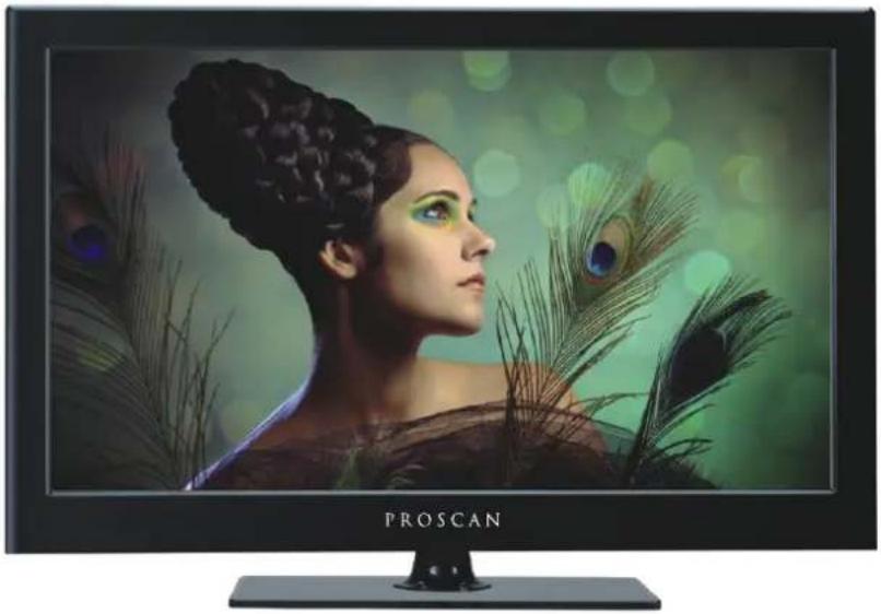
Proscan TV displaying a woman with green makeup and peacock feather decoration (no text or symbols on the screen)Model: PLED4274A

Verified
Energy Performance
Énergie Performance
Verifiér
CONTENTS
| 1 | SAFETY PRECAUTION | 1 | |
| 2 | IMPORTANT SAFETY INSTRUCTION | 2 | |
| 3 | ACCESSORIES | 3 | |
| 4 | GETTING STARTED | 3 | |
| 5 | CONTROL REFERENCE GUIDE | Remote Control | 4 |
| Front View | 5 | ||
| Back View | 5 | ||
| Side View | 6 | ||
| 6 | CONNECTIONS | Antenna Connection | 7 |
| AV Connection | 7 | ||
| Y Pb Pr Connection | 8 | ||
| HDMI Connection | 8 | ||
| VGA Connection | 9 | ||
| Headphone Connection | 9 | ||
| Power Cord Connection | 9 | ||
| Coax(SPDIF) Connection | 10 | ||
| 7 | WALL MOUNT INSTALLATION | 11 | |
| 8 | INITIAL SETUP | Putting The Unit On A Proper Place | 12 |
| Turning The Unit On For The First Time | 12 | ||
| 9 | TV SETUP | Source selection | 13 |
| Main menu | 13 | ||
| Picture Menu | 15 | ||
| Sound Menu | 19 | ||
| Channel Menu | 21 | ||
| Parental Control | 24 | ||
| Setup Menu | 28 | ||
| Other Menu | 30 |
CONTENTS
10
DISPLAY MODE
PC Formats 31 Video Formats 32
11
SPECIFICATION
33
12
TROUBLE-SHOOTING GUIDE
TV Symptom 34
SAFETY CLASS: This is an IEC safety class I product and it must be grounded for safety.
SAFETY PRECAUTION
* CAUTION MARKING WAS LOCATED AT THE REAR OF THE APPARATUS.
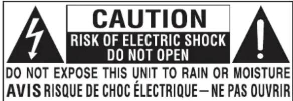
WARNING: TO REDUCE THE RISK OF ELECTRIC SHOCK, DO NOT REMOVE COVER (OR BACK) NO USER SERVICEABLE PARTS INSIDE. REFER SERVICING TO QUALIFIED SERVICE PERSONNEL.
The lightning flash with arrowhead symbol, within an equilateral triangle, is intended to alert the user to the presence of uninsulated "dangerous voltage" within the product's enclosure that may be of sufficient magnitude to constitute a risk of electric shock to persons.
The exclamation point within an equilateral Triangle is intended to alert the user to The presence of important operating and maintenance (servicing) instructions in the literature accompanying the appliance.

- DANGER OF EXPLOSION IF BATTERY IS INCORRECTLY REPLACED. REPLACE ONLY WITH THE SAME OR EQUIVALENT TYPE.
- USE OF CONTROLS OR ADJUSTMENTS OR PERFORMANCE OF PROCEDURES OTHER THAN THOSE SPECIFIED MAY RESULT IN HAZARDOUS RADIATION EXPOSURE.

• TO REDUCE THE RISK OF FIRE OR ELECTRIC SHOCK, DO NOT EXPOSE THIS APPLIANCE TO RAIN OR MOISTURE. TO REVENT FIRE OR SHOCK HAZARD, DO NOT
- EXPOSE THIS UNIT TO RAIN OR MOISTURE. DO NOT PLACE OBJECTS FILLED WITH LIQUIDS ON OR NEAR THIS UNIT.
- SHOULD ANY TROUBLE OCCUR, DISCONNECT THE AC POWER CORD AND REFER SERVICING TO A QUALIFIED TECHNICIAN.
PLACEMENT INFORMATION
- Do not use this unit in places that are extremely hot, cold, dusty or humid.
- Do not restrict the airflow of this unit by placing it somewhere with poor airflow, by covering it with a cloth, by placing it on bedding or carpeting.
SAFETY INFORMATION
- When connecting or disconnecting the AC power cord, grip the plug and not the cord itself. Pulling the cord may damage it and create a hazard.
- When you are not going to use the unit for a long period of time, disconnect the AC power cord.
RATING PLATE LOCATION
The rating plate is located on the rear of the unit.
FCC STATEMENTS
NOTE: This unit has been tested and found to comply with the limits for a Class B digital device, pursuant to Part 15 of the FCC Rules. These limits are designed to provide reasonable protection against harmful interference in a residential installation.
This unit generates, uses and can radiate radio frequency energy and, if not installed and used in accordance with the instructions, may cause harmful interference to radio communication. However, there is no guarantee that interference will not occur in a particular installation. If this unit does cause harmful interference to radio or television reception, which can be determined by turning the unit off and on, the user is encouraged to try to correct the interference by one or more of the following measures:
- Reorient or relocate the receiving antenna.
- Increase the separation between the unit and receiver.
-Connect the unit into an outlet on a circuit different from that to which the receiver is connected. - Consult the dealer or an experienced radio/TV technician for help.

WARNING:
Changes or modifications to this unit not expressly approved by the party responsible for compliance could void the user authority to operate the unit.
IMPORTANT SAFETY INSTRUCTIONS
1) Read these instructions.
2) Keep these instructions.
3) Heed all warnings.
4) Follow all instructions.
5) Do not use this apparatus near water.
6) Clean only with a dry cloth.
7) Do not block any ventilation openings. Install in accordance with the manufacturer's instructions.
8) Do not install near any heat sources such as radiators, heat registers, stoves, or other apparatus (Including amplifiers) that produce heat.
9) Do not defect the safety purpose of the polarized or grounding-type plug.
A polarized plug has two blades with one wider than the other.
A groundingtype plug has two blades and a third grounding prong.
The wide blade or the third prong is provided for your safety.
If the provided plug does not fit into your wall outlet, consult an electrician for replacement of the obsolete outlet.
10) Protect the power cord from being walked on or pinched particularly at plugs, convenience receptacles, and the point where they exit from the apparatus.
11) Only use attachments / accessories specified by the manufacturer.
12) Use only with the cart, stand, tripod, bracket, or table specified by the manufacturer, or sold with the apparatus.
When a cart is used, use caution when moving the cart / apparatus combination to avoid injury from tip-over.
13) Unplug this apparatus during lightning Storms or when unused for long periods of time.
14) Refer all servicing to qualified service personnel. Servicing is required when the apparatus has been damaged in any way, such as the power cord or plug is damaged, liquid has been spilled or objects have fallen into the apparatus, the apparatus has been exposed to rain or moisture, does not operate normally, or has been dropped.
15) To prevent electric shock, ensure the grounding pin on the AC cord power plug is securely connected.

ACCESSORIES
Please check and identify the supplied accessories.
Remote control x 1
Battery(AA) x 2
Warranty Card x 1
Instruction Manual x 1
Base stand and 6 screws x1
Screw driver x 1
GETTING STARTED
USING THE REMOTE CONTROL
-Point the remote control at the remote sensor located on the unit.
- When there is a strong ambient light source, the performance of the infrared remote sensor may be degraded, causing unreliable operation.
·The recommended effective distance for remote operation is about 16 feet (5 meters).
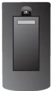
TO INSTALL THE BATTERIES
-
Open the battery door.
-
Insert 2 "AA" batteries
natural_image
Illustration of a cylindrical device with a black panel and a small screen (no text or symbols visible)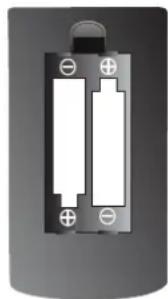
natural_image
Close-up of a cylindrical battery with two white batteries and a terminal block (no text or symbols visible)BATTERY REPLACEMENT
When the batteries become weak, the operating distance of the remote control is greatly reduced and you will need to replace the batteries.

CAUTION : Danger of explosion if battery is incorrectly replaced.
NOTES
- If the remote control is not going to be used for a long time, remove the batteries to avoid damage caused by battery leakage corrosion.
- Do not mix old and new batteries. Do not mix ALKALINE, standard (CARBON-ZINC) or rechargeable (NICKEL-CADMIUM) batteries.
·Always remove batteries as soon as they become weak. - Weak batteries can leak and severely damage the remote control.

WARNING :
Do not dispose batteries in a fire. Batteries may explode or leak.
Batteries shall not be exposed to excessive heat such as sunshine, fire or the like.
CONTROL REFERENCE GUIDE
REMOTE CONTROL
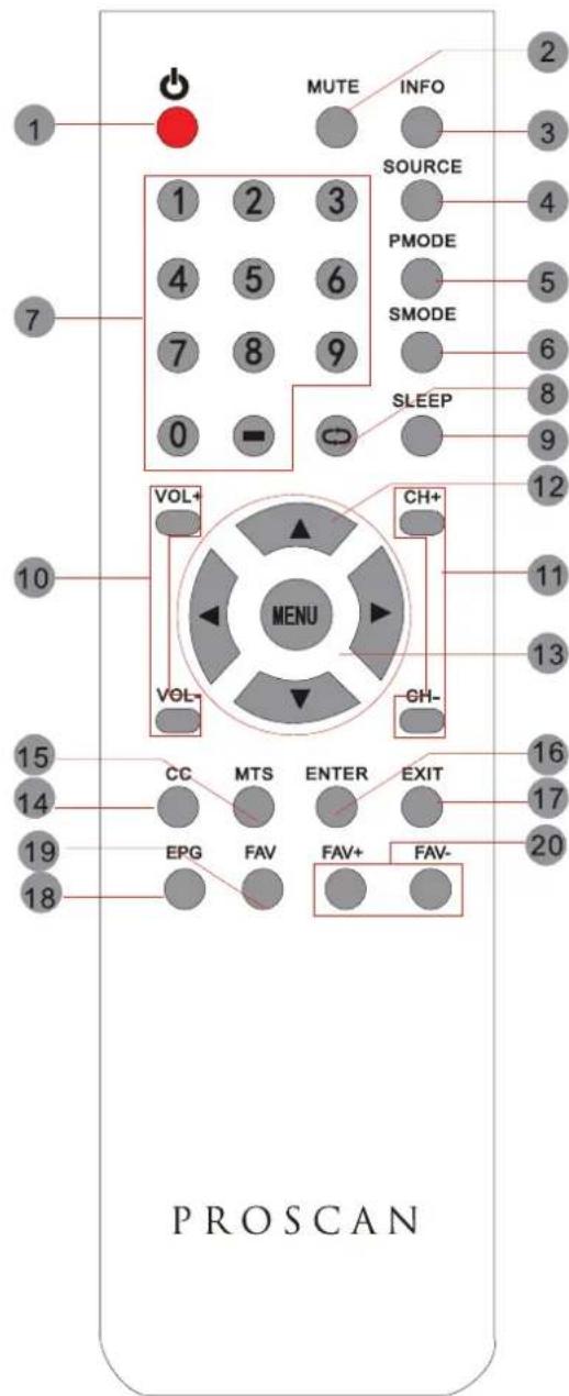
Universal Remote Code: 1218
(Universal Remote Control is not included.)
1.STANDBY
To switch on the TV or make the TV into standby mode.
2.MUTE
Press this button to mute or restore sound.
3.INFO
Show the information of the program you are watching.
4.SOURCE
Press this button to select an input source.
5.PMODE
Press this button to select a picture mode for different picture qualities.
6.SMODE
Press this button to select sound setting for different sound effects.
7.0-9
Allows you to change the channel of the TV.
8.
Switches back and forth between the current and previous channels.
9.SLEEP
To select the amount of time before your TV turns Off automatically.
10.VOL+/VOL-
Increases/Decreases the Volume control.
11.CH+/CH-
Skips to the next/previous channel on TV mode.
Moves the cursor upward/downward/to the left/to the right when making a selection.
13.MENU
Displays the OSD Menu of the TV.
14.CC
Press the button to enter into the CC mode.
15.MTS
To change among STEREO, MONO and SAP. If there is no second language available for the signal received, LCD Display audio will output to mono.
16. ENTER
Press to confirm selections on a menu screen.
17.Exit
Press this button to exit the on screen display.
18.EPG
Press this button to select the electronic programme guide in DTV mode.
19. FAV
Press this button to show the favourite list.
20. FAV+/FAV-
Press this button to go through the FAV channel list.
CONTROL REFERENCE GUIDE
FRONT VIEW
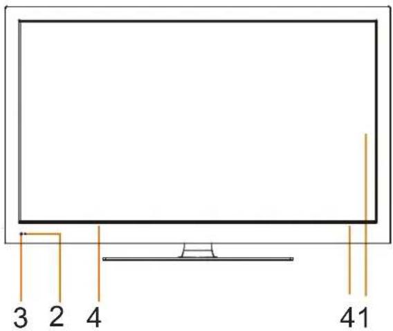
1.Color Screen
2. Standby Indicator
Indicates whether the unit is ON
or in STANDBY (OFF) mode.
Light in red: The unit is in STANDBY.
Light in blue: The unit is turned ON.
3.Remote Sensor
Do not block this sensor or the
remote control will not work.
- Speakers
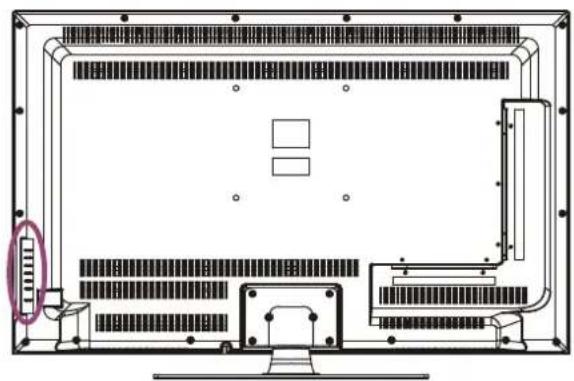
BACK VIEW
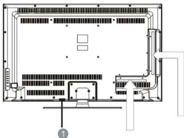
natural_image
Technical line drawing of a mechanical or electrical enclosure with internal components and no visible text or symbols- Power cord
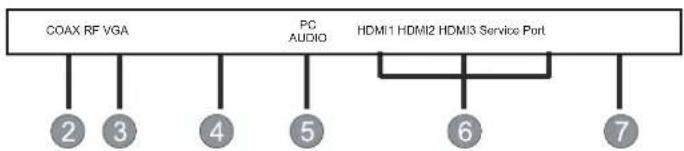
- Coax OUT Jack
3.TV ANTENNA Terminal
4.VGA IN Jack
5.PC AUDIO IN Jack
6.HDMI IN Jack - Service Port
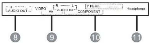
- AUDIO OUT Jack
(Audio out- This connection is for sending out analog audio signal to the 2nd equipment.Red is for Right Channel, white is for Left Channel.)
9.AV (VIDEO/ AUDIO R/L) IN
10.COMPONENT IN Jack - Headphone Jack
flowchart
graph TD
    A["COAX RF VGA"] --> B["2"]
    A --> C["3"]
    A --> D["4"]
    A --> E["5"]
    F["PG AUDIO"] --> G["6"]
    H["HDMI1 HDMI2 HDMI3 Service Port"] --> I["7"]
flowchart
graph TD
    A["[R"] --> B["L"]
    B --> C["VIDEO"]
    C --> D["[R"] --> E["L"]
    E --> F["[Y PL PE"] --> G["COMPONENT"]]
    G --> H["Headphone"]
    I["[AUDIO OUT"]] --> J["8"]
    K["9"] --> L["9"]
    M["10"] --> N["10"]
    O["11"] --> P["11"]
CONTROL REFERENCE GUIDE
BACK VIEW
1 VOL+
2 VOL-
3 CH+
4 CH-
5 —— MENU
6 SOURCE
7 — STANDBY

natural_image
Technical line drawing of a computer monitor front panel with no visible text or symbols- VOL+ Button
Press to adjust the volume up.
- VOL- Button
Press to adjust the volume down.
- CH+ Button
Press to change the TV channels and up highlight selections on the menu screen.
- CH- Button
Press to change the TV channels and down highlight selections on the menu screen.
- MENU Button
Press to display the on-screen TV menu.
- SOURCE Button
Press to select the input source of the TV, and then, press to confirm.
- STANDBY Button
Press to turn the unit on and off.
CONNECTIONS
CONNECTING A TV ANTENNA / CABLE / SATELLITE
To view television channels correctly, a signal must be received from one of the following sources:
- An indoor or outdoor aerial antenna
- A cable system
- A satellite system
NOTE
For receiving over-the-air TV broadcasts, we recommend that you use an external fixed antenna. Should you require the use of a temporary antenna, please ensure that you purchase an antenna with sufficient ability to receive in weak signal areas. Only when you are in close proximity to a transmitter will a temporary antenna reproduce a signal as strongly as a fixed antenna.
natural_image
Technical diagram of a device rear panel with internal components and an external connector (no text or symbols)Satellite, cable or TV antenna cable to TV ANTENNA terminal (cable not included)
CONNECTING AN A/V DEVICE
To connect to other equipment such as a VCR, camcorder, satellite system or cable, etc.
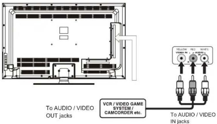
CONNECTING DEVICES WITH A COMPOSITE (YELLOW RCA-TYPE) VIDEO OUTPUT
To connect A/V devices such as a VCR, video game system or camcorder.
Connecting to a VCR / Video Game System / Camcorder
Connect the AUDIO / VIDEO cable (not included) as shown.
Make sure you connect the cable from the other equipment (AUDIO VIDEO OUT) to this unit (AV in)
NOTE
Please refer to the user manual for the other equipment for more information.
CONNECTIONS
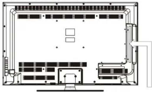
CONNECTING A HIGH-DEFINITION (HD) SOURCE USING CONDEMPONENT
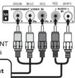
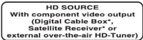
High-Definition (HD) Devices with component video output must be connected to the YPbPr input.
Connect the component video cable and audio cable (not included) as shown.
Make sure you connect the component video cable and audio cable from the other equipment
COMPONENT OUT and AUDIO OUT) to the unit COMPONENT IN.
NOTE
When connecting a DVD player to the television, the picture resolution is solely dependent upon the resolution supported by the DVD player attached. DVD player resolutions vary from 480i to 1080p. and this television can support DVD players up to a maximum resolution of 1080p.
natural_image
Architectural floor plan showing room layouts and ventilation ducts (no text or labels)* May require a subscription for receiving HD channels, check with your cable/satellite service provider for details.
COMPONENT IN
To COMPONENT
VIDEO IN jacks
To COMPONENT AUDIO IN jacks
To COMPONENT VIDEO OUT jacks To COMPONENT AUDIO OUT jacks
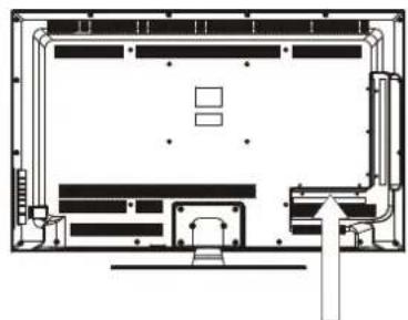
CONNECTING A HIGH-DEFINITION (HD) SOURCE USING HDMI CONNECTION
HDMI (High Definition Multimedia Interface) supports both video and audio on a single digital connection for use with DVD players, DTV, set-top boxes and other digital AV devices. HDMI was developed to provide the technologies of High Bandwidth Digital Content Protection (HDCP) as well as Digital Visual Interface (DVI) in one specification. HDCP is used to protect digital content transmitted and received by DVI-compliant or HDMI compliant displays.
HDMI has the capability to support standard, enhanced or high-definition video plus standard to multi-channel surround-sound audio. HDMI features include uncompressed digital video, a bandwidth of up to 2.2 gigabytes per second (with HDTV signals), one connector (instead of several cables and connectors), and communication between the AV source and AV devices such as DTVs.
natural_image
Architectural floor plan showing room layouts and structural elements (no text or labels)Connect the HDMI cable (not included) as shown:
Make sure you connect the cable from the source equipment ( ) HDMI OUT ( HDMI IN ).
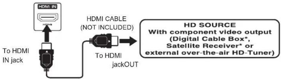
flowchart
graph TD
    A["HDMI IN"] --> B["To HDMI IN jack"]
    B --> C["HDMI CABLE (NOT INCLUDED)"]
    C --> D["To HDMI jackOUT"]
    D --> E["HD SOURCE With component video output (Digital Cable Box*, Satellite Receiver* or external over-the-air HD-Tuner)"]
CONNECTIONS
CONNECTING A PC
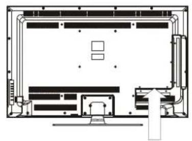
Connect the 15-pin D-SUB PC/VGA connector from your computer to the 15-pin D-SUB PC/VGA input on this unit using a monitor cable and an audio cable (not included) as shown.
Make sure you connect the cable from the computer (VGA) to this AUDIO - PC OUT (VGA AUDIO - PC IN
natural_image
Architectural floor plan showing room layout with furniture and structural elements (no text or labels)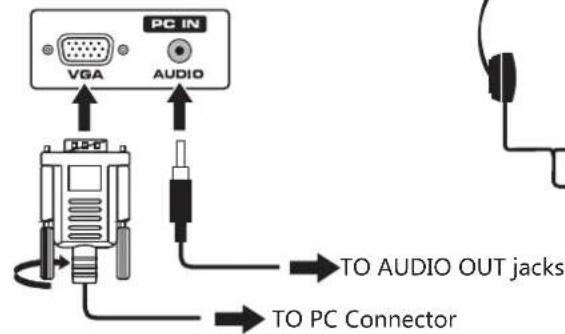
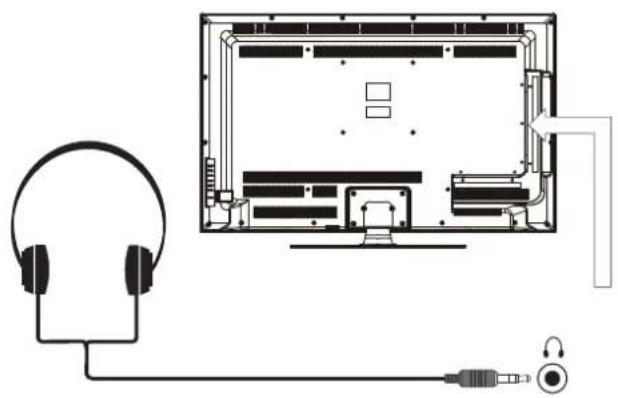
CONNECTING HEADPHONES
- Turn down the volume before connecting headphones to the unit, then adjust the volume to your desired level.
- When headphones are connected, no sound will come from the front speakers.
NOTE
Avoiding listening to sound at high Levels for prolonged period of time. This may be harmful to you and may cause hearing loss.
natural_image
Diagram showing a headset connected to an open computer monitor with cable and connector (no text or symbols)Headphones (1/8"[3.5mm]diameter plug) NOT INCLUDED
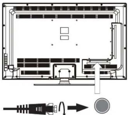
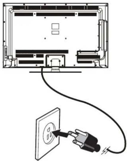
You can power on your TV unit before you make sure the power cord is inserted well. At the same time, please check that the rated voltage of your unit matches your local Voltage.
NOTE
- Insert the power plug fully into the socket outlet. (If the power plug is loose, it could generate heat and cause fire.)
- Ensure that the power plug is easily accessible.
- Ensure the earth pin on the power plug is securely connected to prevent electrical shock.
• An apparatus with CLASS I construction shall be connected to a power socket outlet with a protective grounding connection.
- Do not touch the power plug with a wet hand. (This may cause electrical shock)
- Do not use any power cord other than that provided with this TV. (This may cause fire or electrical shock
- Do not damage the power cord. (A damaged cord may cause fire or electrical shock)
- Do not move the TV with the cord plugged in the socket outlet.
- Do not place a heavy object on the cord or place the cord near a high-temperature object.
- Do not twist the cord, bend it excessively, or stretch it.
- Do not pull on the cord. Hold onto the power plug body when disconnecting cord.
- Do not use a damaged power plug or socket outlet.
natural_image
Diagram showing a cable being inserted into an electrical outlet with a plug, no text or symbols presentTo AC wall outlet
CONNECTIONS
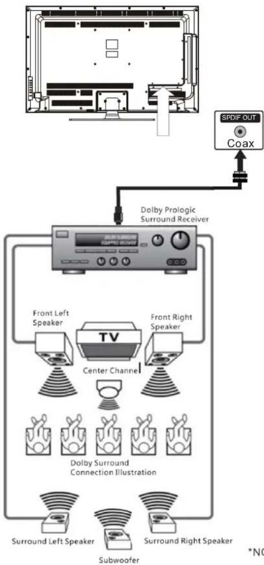
Connection to a Home Theater Audio System
For BEST audio performance
Connecting to a Home Theater System Dolby Digital can deliver optimal 2 channel stereo or surround sound with five discrete full range channels plus a sixth channel for a subwoofer.
Enjoy optimal sound reproduction from your system with a Dolby Digital amplifier that incorporates a digital coaxial input. Connect an optional digital cable directly to the television's Coax audio output to listen through all inputs except VGA.
(The VGA does not support digital audio)
How To Setup Digital Output
Press the MENU button on the remote control Press the right ▶ arrow button to select SOUND and Press ENTER to enter the submenu. Press the down ▼ arrow button to highlight Digital Audio Output and press ◀▶ to change setting from PCM, Raw or Off.

SOUND
Sound Settings
Surround Mode
AVL
Analog Sound
Digital Sound
Digital Audio Output
Equalizer Settings

Stereo
English
PCM

:Return ▲:Move

:Change Setting
flowchart
graph TD
    A["SPDIF OUT"] --> B["Coax"]
    B --> C["Dolby Prologic Surround Receiver"]
    C --> D["Front Left Speaker"]
    C --> E["Front Right Speaker"]
    D --> F["TV Center Channel"]
    E --> F
    F --> G["Dolby Surround Connection Illustration"]
    G --> H["Surround Left Speaker"]
    G --> I["Surround Right Speaker"]
    H --> J["Subwoofer"]
    I --> K["*NC"]
optional digital cable
*NOTE: Refer to the User Manual from your home theater equipment for recommended audio settings.
WALL MOUNT INSTALLATION
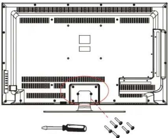
INSTALLING / REMOVING THE BASE STAND
WARNING : The LED Display is very fragile, and must be protected at all times when removing the base Stand.
Be sure that no hard or sharp object or anything that could scratch or damage the LED display comes into contact with it. Do NOT exert pressure on the front of the unit at any time because the screen could crack.
1 Disconnect all cables or cords connected to the unit.
2. Lay the unit down on a flat surface with the back side facing up. Please make sure to place a soft cushioned material (such as a pillow or thick piece of foam) beneath the screen.
3. To remove the base stand, loosen screws off the holes then pull downwards to release the base stand.
natural_image
Technical line drawing of a computer monitor rear panel with screwdriver and screwdriver (no text or symbols)MOUNTING ON THE WALL
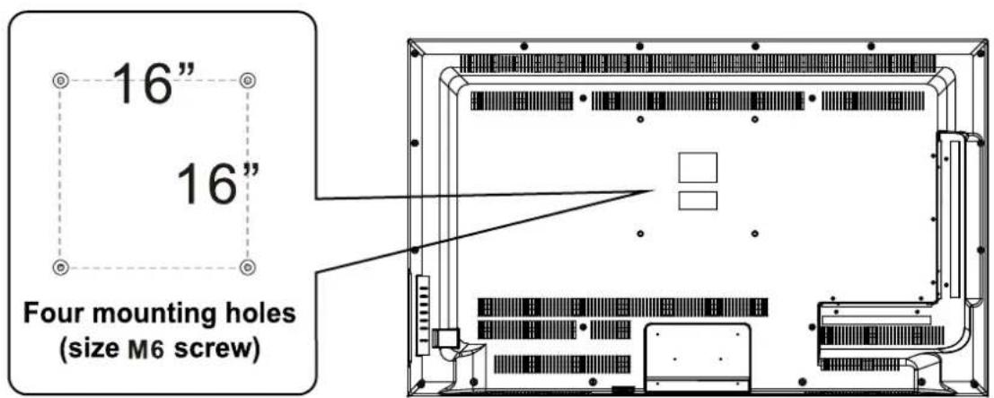
This unit is VESA-compliant, and is designed to be wall-mounted with a VESA-compliant 16" x 16" (400mm x 400mm) mounting kit designed for flat-panel TVs (not supplied). Mount this unit according to the instructions included in the mounting kit. Length of screw should not exceed 10 mm.
NOTE
Remove the base stand before mounting the unit on the wall.
INITIAL SETUP
PUTTING THE UNIT ON A PROPER PLACE
When you turn on your television set for the first time, be sure to place it on a solid stable surface.
To avoid danger, do not expose the TV to water, or a heat source (e.g. lamp, candle, radiator).
Do not obstruct the ventilation grid at the rear and be sure to leave sufficient gaps around the unit.
natural_image
Proscan TV displaying a woman in a stylized headdress with feather decoration (no visible text or symbols on screen)TURNING THE UNIT ON FOR THE FIRST TIME
After you have initially connected your TV antenna or cable, turn the television ON.
A screen will display asking you to run a Initial Setup menu to search and receive available local digital channels.
It is where you will select Menu Language and choose your Signal Type between Air and Cable.
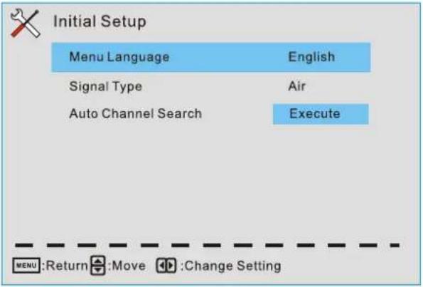
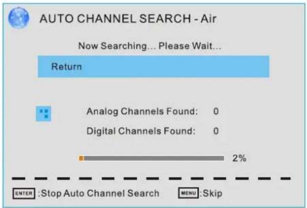
After that, you can choose Auto Channel Search and then it will search analog channels first, then digital channels.
Before execute auto channel search, please confirm your antenna type is Air or Cable. Wrong setting of Signal Type maybe cause finding no channel.
TV SETUP
SOURCE SELECTION
- Press the SOURCE button on the remote control.
- Use the ▲ or ▼ button to select the options (TV, AV, YPbPr, HDMI1, HDMI2, HDMI3, PC)
and select any of them using the ▶ button or the ENTER
(The screen will change to your desired source).
Note:
Before wa tching please ma ke sure all necessary cables and devices are connected.
| Source Select |
| TV |
| AV |
| YPbPr |
| HDMI1 |
| HDMI2 |
| HDMI3 |
| PC |
Main MENU
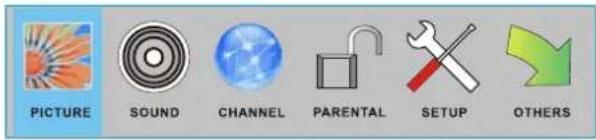
Press MENU to display the main menu or return to the previous menu or close the main menu.
Press ◀/▶ to high light the desired menu icon, and press ENTER to select. If no buttons are pressed, the menu will close automatically after about 10 seconds.
Main Menu Description
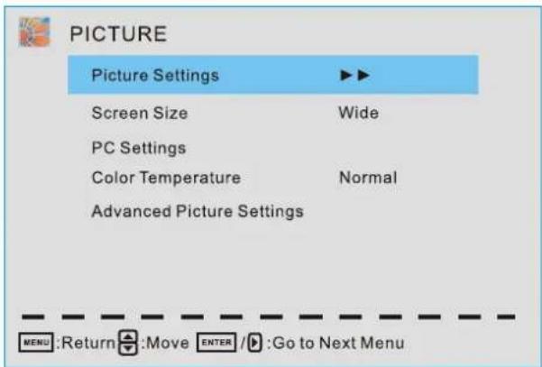
Picture Menu
Adjust your picture settings.
The operations are slightly different among different source.
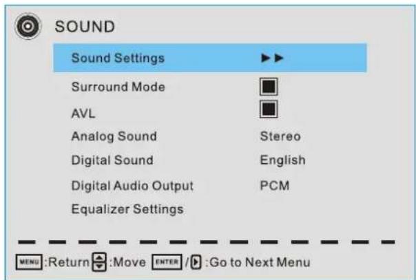
Sound Menu
Adjust the sound settings.
TV SETUP

CHANNEL
Channel List

Favorite List
Channel Settings
Signal Type
Air
Auto Channel Search
Execute


:Move

/▶:Go to Next Menu

PARENTAL CONTROL
Lock Parental Control

V-CHIP
Change Password

Return

:Enter password

SETUP
Closed Caption

Menu Language
English
Clock


:Move

/▶:Go to Next Menu

OTHERS
Blue Back

No Signal Power Off

No Operation Power Off

All Reset
Execute
Audio Only
Execute


:On/Off
Channel Menu
Customize your channel settings.
Parental Control Menu
Set program rating control.
Setup Menu
Select closed caption options, language and time.
Other Menu
Set the OSD blue background, whether auto power off if no signal or no operation, clear all user settings, etc.
TV SETUP
Picture Menu
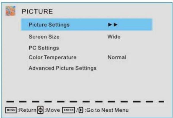
Press ▲/▼ to highlight one of the following options, then press ENTER or ▶ to enter next submenu to adjust it. Press EXIT to clear on-screen menu or MENU back to the previous menu.
Picture Settings
Adjust the picture quality including brightness, contrast, color, tint, sharpness.
Screen Size
Press ◀/▶ to select the display aspect ratio till the picture is fit onto the screen. The operations are different according to different input source.
PC Settings
The item is available only for PC DB15 input mode.
Color Temperature
Press ◀/▶ to select the color temperature that you feel comfortable.
Cool Gives white colors a blue tint.
Normal Gives white colors a neutral tint.
Warm Gives white colors a red tint.
Advanced Picture Settings
The Item is some special picture feature.
TV SETUP
Picture Settings
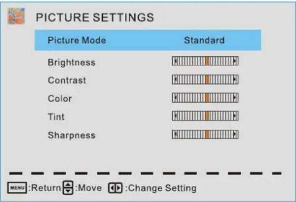
When Picture Mode is set to User, the following setting can be manually adjusted. Press PMODE shortcut button on the remote control to select picture mode directly.
Picture Mode
Highlight the item and Press ◀/▶ to select Standard/ Movie/ User/ Dynamic.
Standard Produces a highly defined image in a normally lit room.
Movie Produces a highly defined image in gentle lit room.
User Select to customize picture setting.
Dynamic Produces a highly defined image in a bright lit room.
Highlight the item and press ▶, and a process bar appears, then press ◀/▶ to adjust the value. Tint is available when analog TV or NTSC-system AV. Press MENU to back the Picture Settings menu.
Brightness
Adjust darkness of black sections in the picture.
Contrast
Adjust the white level of the picture.
Color
Adjust the color intensity of the picture.
Tint
Adjust the hue( Red, Green, Blue) of the picture.
Sharpness
Object edges are enhanced for picture detail.
TV SETUP
PC Settings
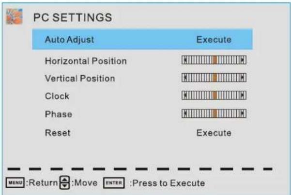
PC Settings Menu is available only in PC DB15 mode.
Press ▲/▼ to highlight one of the following options, then press ENTER to select it.
Auto Adjust
Automatically adjust Clock, Phase, H-Position and V-position settings.
Horizontal Position
Shift the screen slightly to left or right.
Vertical Position
Shift the screen slightly up or down.
Clock
Adjust the DB 15 Picture signal sampling clock rate.
Phase
Adjust the DB 15 Picture signal sampling phase. It maybe affect the definition. Wrong value maybe result the interference.
Reset
Reset the parameters of current menu to default value.
TV SETUP
Advanced Picture Settings
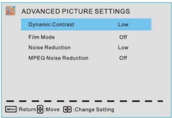
Press ▲/▼ to highlight the item and press ENTER or ▶ to display the submenu as following.
Dynamic Contrast Off/ Low/ Medium/ High
The system will adjust the luminance curve by analyzing the picture content dynamically.
Film Mode Off/ On
For the 2:2 or :2 format signal of cinema, enable special pixel process to reduce the flick of moving area.
Noise Reduction Off/ Low/ Medium/ High
You can clear up analog TV signal by reducing the dot noise. This feature is not available at PC source.
MPEG Noise Reduction Off/ Low/ Medium/ High
Similar with the Noise Reduction, you can set to reduce the block noise.
TV SETUP
Sound Menu
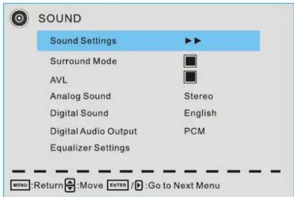
Sound Settings
Set the sound mode, and Bass/ Treble/ Balance.
Surround Mode
Set to enjoy the virtual surround sound. Press ENTER to set or cancel.
AVL
Auto Volume Level. Press ENTER to set or cancel. When AVL is set on, it will limit the sound being heard when sudden changes in volume occur during commercial breaks or channel changes.
Usually be enabled at night.
Analog Sound
Available at analog TV channels, SAP/ Stereo/ Mono
Set the preferred sound track of analog channels. Stereo and SAP exist on some channels.
Generally SAP is a second language sound or help the people with hearing impair.
Digital Sound
Available at digital TV channels, English/ French/ Spanish
Set the preferred sound track of digital channels, French and Spanish exist on some channels.
Digital Audio Output PCM/ Raw/ Off
Set the audio output type of coax or optical terminal. Raw means output the original format of audio stream. PCM can be matched with most AV amplifiers.
Equalizer Settings
Adjust the curve of 7 bands equalizer.
TV SETUP
Sound Settings
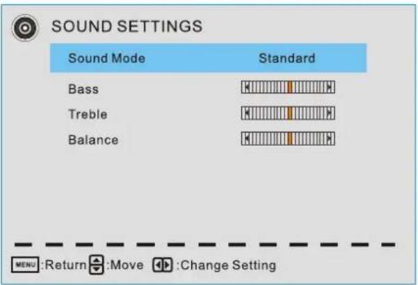
Sound Mode Standard/ Soft/ User/ Dynamic
Only in User mode, the following items can be adjusted.
Bass
Adjust the low frequency band response.
Treble
Adjust the high frequency band response.
Balance
Adjust the level of sound coming from the left or right speaker.
Adjust the Bass/ Treble/ Balance
- Set sound mode to User.
- Highlight the item and press ▶ to display the submenu, the press ◀/▶ to adjust the value.
TV SETUP
Equalizer Settings
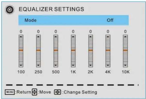
bar
EQUALIZER SETTINGS | Mode | Value | | :--- | :--- | | Return | 0 | | Move | 0 | | Change Setting | 0 |Mode Off/ Rock/ Pop/ Jazz/ User( only in User mode, the following can be manually adjusted.)
Adjust Equalizer Settings
Based on your favorites about which frequency band need to be adjusted, make small adjustment with certain frequency band at a time. Suggest NOT making too large changes.
- Set mode to User.
- Press ▼ to select the first(100Hz) item, then press ◀/▶ to select the band to be turned.
- Press ▲/▼ to adjust the value.
Channel Menu
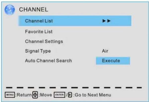
Note: The menu is available only at TV source.
TV SETUP
Channel List
You can view all the channels and choose one quickly.
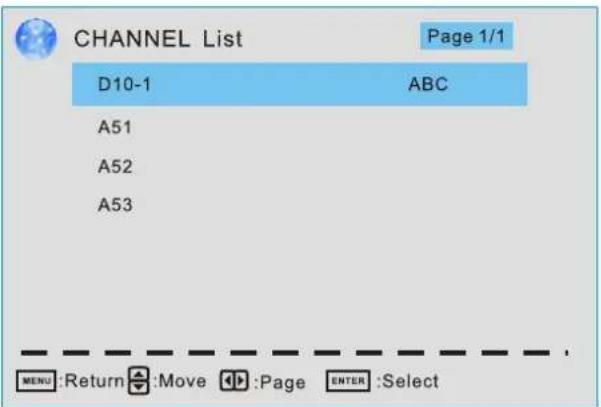
"ABC": Label of the Channel.
Press ▲/▼ to highlight a channel and press ENTER to view it.
Favorite List
All of you favorite channels are listed in this menu, and you can choose them quickly.
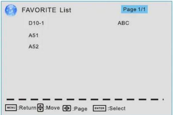
Channel Setting
Set the favorite channels, skipped channels, label of channels.
Signal Type
Set to Air or Cable according to your antenna source.
TV SETUP
Auto Channel Search
Highlight and press ENTER to start the auto searching.
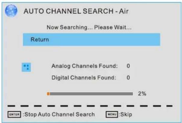
It will search analog channels first, then digital channels.
Before execute auto channel search, please confirm your antenna type is Air or Cable. Wrong setting of Signal Type maybe cause finding no channel.
Channel Settings
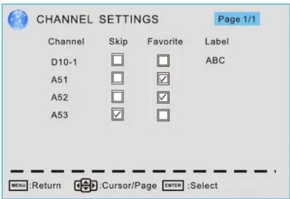
Skip
Set the channel to be skipped when using CH+/CH- to view channels.
Favorite
Set the channel to your favorite list.
Label
Rename label of the channel.
Change the settings
Skip & Favorite
- Press ▲/▼ to select the channel you want to set.
- Press ◀/▶ to highlight corresponding item, and press ENTER to set or cancel.
Label
- Press ▲/▼ to select the channel and ENTER to enter the edit state.
- Press ▲/▼ to select the character, press ◀/▶ to move the cursor. Total seven letters.
TV SETUP
Parental Control
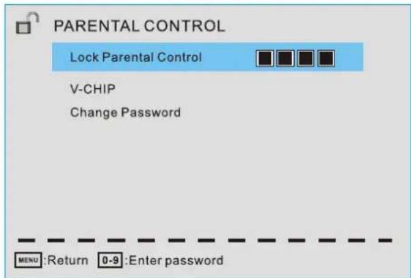
Note: The default user password is "0000", and if forget what you set, try"1470".
Lock Parental Control
The following items are only available if the password input is correct.
V-CHIP Include below settings:
US V-Chip
Rating system used at USA.
Canada V-Chip
Rating system used at Canada.
Block UnRated Show
Control whether lock the program that have not any valid rating flag.
Downloadable Rating
Control the RRT5 setting which are valid only at some digital cable channels.
Clear Downloadable Data
Select to clear the previous downloadable rating data.
Change Password
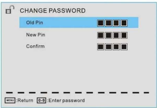
Enter a 4-digital number you want to set.
TV SETUP
US V-CHIP
For the United States, the rating setting basically include the following options:
Movie Rating, TV Rating.
Moive Rating
This system defines the rating control which come from MPAA rules
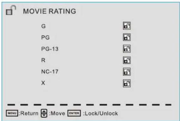
Rating Define
| G | General audience. All ages admitted. |
| PG | Parental guidance suggested . Some material may not be suitable for child ren. |
| PG-13 | Parents strongly cautioned. Some material may be inappropriate for children under 13. |
| R | Restricted. Children under 17 require accompanying parent or adult guardian. |
| NC-17 | No one 17 and under admitted |
| X | Adult audience only. |
TV SETUP
TV Rating
The TV rating compose of two aspects: age-based and content-based.
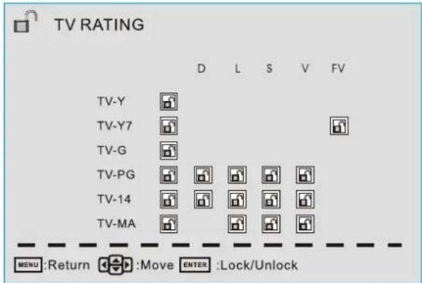
| Content | Define |
| FV | Fantasy violence |
| D | Suggestive dialogue |
| L | Strong language |
| S | Sexual situations |
| V | Violence |
| Age | Define |
| TV-Y | General audience |
| TV-Y7 | Parental guidance suggested |
| TV-G | Parents strongly cautioned |
| TV-PG | Retricted |
| TV-14 | No one 17 and under admitted |
| TV-MA | Adult audience only |
Note: The content ratings will increase depending on the level of the age-based rating. For example, a program with a TV-PG V(violence) rating may contain moderate violence, while a TV-14 V(violence) rating may contain intense violence. So locking a higher level option will automatically cause locking the option that has more sensitive level.
TV SETUP
Canada V-CHIP
For Canada, the rating setting include the following options: English rating, French Rating.
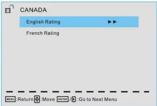
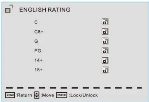
English Rating
These ratings are for programs which are using English rating system.
| Rating | Defined as |
| C | Children |
| C8+ | Children 8 years and older |
| G | General programming |
| PG | Parental guidance |
| 14+ | Viewers 14 and older |
| 18+ | Adult programming |
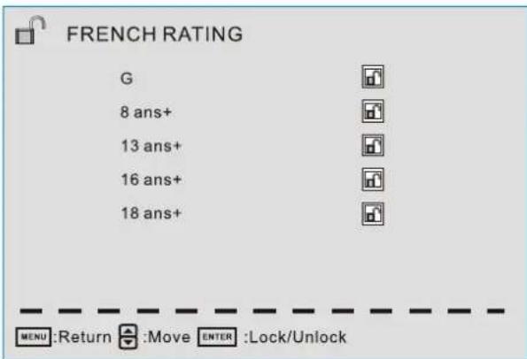
French Rating
These ratings are for programs which are using French rating system.
Rating Defined as
| G | General |
| 8 ans+ | Not recommended for younger children |
| 13 ans+ | Not recommended for children under age 13 |
| 16 ans+ | Not recommended for ages under 16 |
| 18 ans+ | This program is restricted to adults |
TV SETUP
Change Password
At first you should enter the correct old password then enter new password twice.
If you lost your password, try to enter "1470".
Setup Menu
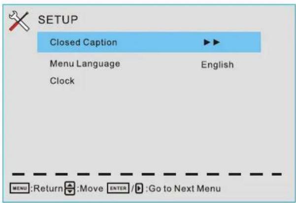
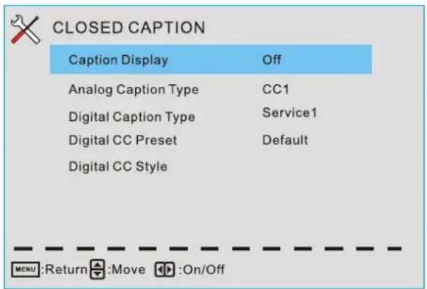
Closed Caption(CC)
Menu Language
Set the menu language. English/French/Spanish.
Clock
Set the Time Zone/ Auto Clock/ Setup Time/
Day of week/ Daylight Saving Time.
Caption Display
Display or hide the CC.
Analog Caption Type
Select from closed-caption modes for analog programs.
Digital Caption Type
Applies only to digital channels with closed caption.
Digital CC Preset Default/Custom
If set to Custom, Digital CC Style is available.
TV SETUP
Digital CC Style
This menu is valid only for digital closed caption of digital channels.
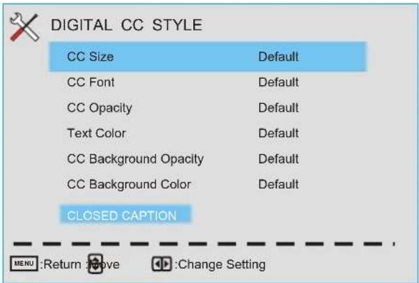
CC Size Small/Standard/Large/Default
CC Font Style0\~7,Default
CC Opacity Default/Solid/Flashing/Translucent/Transparent/Default.
Text Color Black/White/Red/Green/Blue/Yellow/Magenta/Cyan/Default.
CC Background Opacity Solid/Flashing/Translucent/Transparent/Default.
CC Background Color Black/White/Red/Green/Blue/Yellow/Magenta/Cyan/Default.
Clock
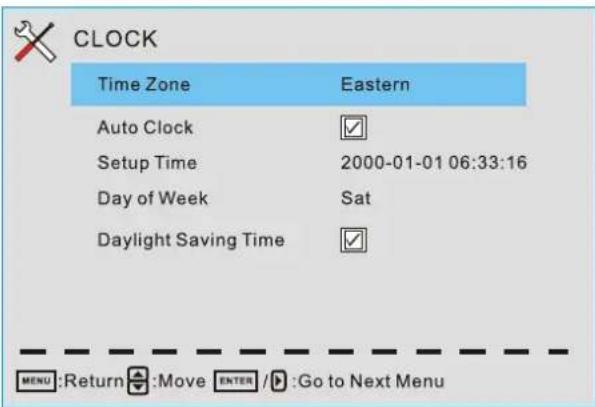
Time Zone Hawaii/Alaska/Pacific/Centra/Mountain/Eastern/Samoa/Newfounland/Altantic Set the time zone.
Auto Clock
If set it to ON, the TV will sync the local clock according to the DTV broadcasting time automatically. Otherwise you can set the time manually.
Setup Time
Set Auto Clock to Off, then you can set the time manually.
Note: In the case of loss of power, the clock setting will be lost
Day of Week
The TV will calculate current day of week according to the time.
Daylight Saving Time
When Auto Clock set to ON, this item is available to enable daylight saving option or not.
TV SETUP
Others Menu
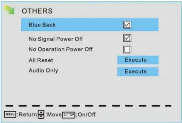
Blue Back
Set the screen background color blue or not when no valid signal input. When analog TV input and has no signal, snow noise will display if this option is cleared.
No Signal Power Off
If it is set, TV will automatically enter standby after 10 minutes without signal input.
No Operation Power Off
If it is set, TV will automatically enter standby after 3 hours without any operation.
All Reset
When you highlight the item, the system will note you that"Attention! If [All Reset] was executed, TV system is reset", and if you are sure to reset, press ENTER to reset.
Audio Only
When you highlight the item, the system will note you that "Attention! Hold on power key 3 second to restore video", and if you are sure not need to view (backlight is turned off), press ENTER to confirm. As the attention, if you want to wake up the video, please hold on the power button for 3 seconds.
DISPLAY MODE
PC FORMATS
| SUPPORTED PC INPUT MODE | |||
| Resolution | Hi o aor z nt l Scanning Frequency (KHz) | Vertical Scanning Frequency (Hz) | Format |
| 640 x 480 | 31.5 | 60.0 | DOS |
| 800 x 600 | 35.1 | 56.2 | VESA |
| 800 x 600 | 37.9 | 60.0 | VESA |
| 1024 x 768 | 48.4 | 60.0 | VESA |
| 1920 x 1080 | 66.6 | 60.0 | VESA |
NOTE:
This product does not support the display mode not listed above.
In order to achieve the best display effect, please select the above-listed 5 display modes input signal.
Because of the difference of display drivers output signal
(especially non-standard signal output), the display image may appear little disturbance which can be adjusted on the PC menu.
To prolong this unit's service life, please set your computer to power management mode.
DISPLAY MODE
VIDEO FORMATS
| SUPPORTED COMPONENT / HDMI INPUT MODE | |||
| e iRisφ on | Horizontal Scanning Frequency ( KHz ) | Vertical Scanning Frequency (Hz) | Format |
| 720 480 | 31. 47 | 59. 94 | 480 i |
| 720 480 | 15. 734 | 59. 94 | 480 p |
| 1280 720 | 37. 5 | 50 | 720 p |
| 1280 720 | 45 | 60 | 720 p |
| 1920 1080 | 31. 25 | 50 | 1080 i |
| 1920 1080 | 33. 75 | 60 | 1080 i |
| 1920 1080 | 27 | 24 | 1080 p |
| 1920 1080 | 56. 25 | 50 | 1080 p |
| 1920 1080 | 67. 50 | 60 | 1080 p |
NOTE:
The above listed formats are also related to the AV devices you are about to connect. Before you connect this unit with others please read all instructions carefully and make sure all necessary cables are connected.
This unit may be incompatible with some other formats which are not meet the above conditions.
SPECIFICATION
| Model Description | 42"LED TV | |
| Panel | Panel Type | LED Panel |
| Diagonal Size | 42 inches | |
| Screen Format 16 9: | ||
| Resolution | 1920 x1080 | |
| Brightness | 360 nit | |
| Contrast | 1400:1 | |
| View Angle | 178(H)/178(V) | |
| Response Time | 8 ms | |
| Maximum Color | 16.7M colors | |
| Refresh Rate | 60Hz | |
| Systems | Color System | ATSC/QAM/NTSC |
| Sound System | M | |
| Audio System | MTS | |
| Sound Output | L/R Speaker: 10 W + 10W | |
| Input / Output Jacks | RF Input 75 ohm external terminal | |
| HDMI Input | Video 480i 480p 720p 1080i, 1080p.: , , ,Audio: Two channel linear PCM 32, 44.1 and 48kHz, 16, 20 and 24 bits | |
| PG-RGB Input | D-sub 15pinG: 0.7Vp-p, 75ohmsB: 0.7Vp-p, 75ohmsR: 0.7Vp-p, 75ohms | |
| Composite Video Input | 1.0 Vp-p, 75ohms RCA | |
| Component/Y Pb Pr Input | RCAY: 1.0 Vp-p, 75ohms, 0.3V negative syncPb: 0.7Vp-p, 75ohmsPr: 0.7Vp-p, 75ohms | |
| Sound Input | Component AUDIO: For Component Audio inputAV AUDIO: For CVBS Audio inputPC AUDIO: For PC RGB Audio input500mV rms, Impedance: 20k ohms | |
| Power | Power Requirement | 100-240V~ 50/60Hz |
| Rated power consumption | 68W | |
This manual is only for your reference.
Specifications are subject to update without prior notice.
TROUBLESHOOTING GUIDE
SYMPTOM CAUSE AND REMEDY( )
| TV | |
| Bad Picture (snow, multiple images distortion, blurry) | Check the location of the antenna and adjust it if necessary.Make sure the antenna cable is firmly connected.Make sure all input cables are firmly connected. |
| No sound. | Increase the volume.Check whether the mute function has been activated on the Remote Control. |
| Black and White picture. | Check the PICTURE setting within the PICTURE menu.Check to make sure the program you are watching is broadcast in Color and not Black & White. |
| No picture or sound. | Make sure the unit is plugged in and turned on.Make sure that the ATV mode is selected.Try a new channel to check for possible station trouble.Make sure the antenna is connected properly.Increase the volume.Make sure the antenna or audio/video source device is working properly.Make sure all cables are firmly connected.Check for local interference. |
| Coloredpatches of picture. | Make sure there are no unshielded electrical devices nearby that are causing interference.Turn the TV off for 30 minutes, then try it again. |
| Panel function key does not respond correctly. | Under the influence of electrostatic phenomenon, the product may malfunction and require usertopowerreset.Unplug and re-plug the AC power cord. |
| The display monitor's panel goes hot. | LED TV takes inside lighten phosphor. It may increase the temperature of the screen in some occasions. It's not a defect. |
| Unusual dots | Black dots and Bright points may appear on the LED screen.This is a structural property of the LED panel and is not a defect. |
| Stripes on screen | Adjust the impulse phase may decrease stripes. (RGB in ) |
| The top of the monitor gets hot. | It may occur during long-time working. It's not a defect. |
| Unable to select a certain channel. | The channel may be skipped. Choose this channel by directly selecting the buttons from the remote control. |
| Disorder display at power on. | This may be caused because of a very short interval between POWER OFF and ON.Unplug the power and restart. |
- CONTENTS
- SAFETY PRECAUTION
- PLACEMENT INFORMATION
- SAFETY INFORMATION
- RATING PLATE LOCATION
- FCC STATEMENTS
- WARNING:
- IMPORTANT SAFETY INSTRUCTIONS
- ACCESSORIES
- GETTING STARTED
- USING THE REMOTE CONTROL
- TO INSTALL THE BATTERIES
- BATTERY REPLACEMENT
- NOTES
- WARNING :
- CONTROL REFERENCE GUIDE
- REMOTE CONTROL
- 1.STANDBY
- 2.MUTE
- 3.INFO
- 4.SOURCE
- 5.PMODE
- 6.SMODE
- 7.0-9
- 8.
- 9.SLEEP
- 10.VOL+/VOL-
- 11.CH+/CH-
- 13.MENU
- 14.CC
- 15.MTS
- ENTER
- 17.Exit
- 18.EPG
- FAV
- FAV+/FAV-
- FRONT VIEW
- BACK VIEW
- CONNECTIONS
- CONNECTING A TV ANTENNA / CABLE / SATELLITE
- NOTE
- CONNECTING AN A/V DEVICE
- CONNECTING DEVICES WITH A COMPOSITE (YELLOW RCA-TYPE) VIDEO OUTPUT
- CONNECTING A HIGH-DEFINITION (HD) SOURCE USING CONDEMPONENT
- CONNECTING A HIGH-DEFINITION (HD) SOURCE USING HDMI CONNECTION
- CONNECTING A PC
- CONNECTING HEADPHONES
- Connection to a Home Theater Audio System
- For BEST audio performance
- How To Setup Digital Output
- SOUND
- WALL MOUNT INSTALLATION
- MOUNTING ON THE WALL
- INITIAL SETUP
- PUTTING THE UNIT ON A PROPER PLACE
- TURNING THE UNIT ON FOR THE FIRST TIME
- TV SETUP
- SOURCE SELECTION
- Main MENU
- Main Menu Description
- Picture Menu
- Sound Menu
- CHANNEL
- PARENTAL CONTROL
- SETUP
- OTHERS
- Channel Menu
- Parental Control Menu
- Setup Menu
- Other Menu
- Picture Settings
- Screen Size
- PC Settings
- Color Temperature
- Advanced Picture Settings
- Picture Mode
- Brightness
- Contrast
- Color
- Tint
- Sharpness
- Auto Adjust
- Horizontal Position
- Vertical Position
- Clock
- Phase
- Reset
- Sound Settings
- Surround Mode
- AVL
- Analog Sound
- Digital Sound
- Digital Audio Output PCM/ Raw/ Off
- Equalizer Settings
- Bass
- Treble
- Balance
- Adjust the Bass/ Treble/ Balance
- Adjust Equalizer Settings
- Channel List
- Favorite List
- Channel Setting
- Signal Type
- Auto Channel Search
- Channel Settings
- Skip
- Favorite
- Label
- Change the settings
- Skip & Favorite
- Lock Parental Control
- Change Password
- US V-CHIP
- Moive Rating
- TV Rating
- Canada V-CHIP
- English Rating
- French Rating
- Closed Caption(CC)
- Menu Language
- Caption Display
- Analog Caption Type
- Digital Caption Type
- Digital CC Preset Default/Custom
- Digital CC Style
- Auto Clock
- Setup Time
- Day of Week
- Daylight Saving Time
- Others Menu
- Blue Back
- No Signal Power Off
- No Operation Power Off
- All Reset
- Audio Only
- DISPLAY MODE
- NOTE:
- SPECIFICATION
- TROUBLESHOOTING GUIDE
Brand : Proscan
Model : PLED4274A
Category : Television