
LOC90 - Audio/video converter Scosche - Free user manual and instructions
Find the device manual for free LOC90 Scosche in PDF.


| Product Type | Line Output Converter (LOC) |
| Model | LOC90 |
| Brand | Scosche |
| Category | Audio/Video Converter |
| Input Channels | 2 (Left/Right) speaker-level input |
| Output Channels | 2 (Left/Right) RCA output |
| Input Impedance | 12 ohms |
| Output Impedance | 100 ohms |
| Gain Adjustment | Variable 0.5V to 8V |
| Frequency Response | 20 Hz - 20 kHz |
| Signal-to-Noise Ratio | > 90 dB |
| Total Harmonic Distortion | < 0.05% |
| Power Supply | 12V DC, 500mA |
| Dimensions (W x H x D) | 3.5 x 1.2 x 2.8 inches |
| Weight | 0.25 lbs |
| Remote Turn-On | Yes (12V trigger) |
| Ground Isolation | Yes (eliminates ground loops) |
| Noise Filter | Low-pass filter (variable cutoff) |
| LED Indicator | Power on/off |
| Mounting | Bracket or double-sided tape |
| Compatibility | Factory stereo systems with speaker outputs |
| Installation | Single screw connectors for input/output |
Frequently Asked Questions - LOC90 Scosche
User questions about LOC90 Scosche
0 question about this device. Answer the ones you know or ask your own.
Ask a new question about this device
Download the instructions for your Audio/video converter in PDF format for free! Find your manual LOC90 - Scosche and take your electronic device back in hand. On this page are published all the documents necessary for the use of your device. LOC90 by Scosche.
USER MANUAL LOC90 Scosche
natural_image
Technical line drawing of an electronic device with two connected modules, no visible text or symbolsINTRODUCTION
The LOC90 converts speaker wire (high-level) to RCA outputs (low-level) for the purpose of adding a 2-channel or mono amplifier to an existing factory or aftermarket stereo system. The LOC90 features up to 4 volt output and signal sensing turn-on with ability to drive a relay. The LOC90 also includes a convenient remote mountable volume control for precise control over subwoofer amplifier level from up front in the vehicle.

IMPORTANT!
DO NOT RETURN PRODUCT TO THE RETAILER
IF YOU NEED ASSISTANCE OR REPLACEMENT PARTS CALL US TOLL FREE: 1-800-621-3695 X3
HOURS MON-FRI 8AM-5:30PM (PST) SATURDAY 8AM-2PM (PST)
PRELIMINARY
BEFORE BEGINNING: READ THESE INSTRUCTIONS!
**CAUTION**: Disconnect negative battery terminal to avoid short circuits. Read ALL manufacturers warnings regarding air bags and electrical systems in your vehicle. We recommend the use of a volt-ohm meter or computer-safe LED probe when checking wiring. A test light or grounded light probe if used improperly can cause damage to the vehicle's computer and/or diagnostic system.
RECOMMENDED TOOLS (not included)
TESTING/DIAGNOSIS: Digital volt/ohm meter or electronics-safe volt probe
WIRE SPLICE/CONNECTIONS: Wire crimper/strippers, soldering iron/heat shrink or buttsplice crimp connectors, cable ties
SPECIALTY: Vehicle panel popper, trim removal tools, wire/cable fishing puller tool
LOC90 OVERVIEW
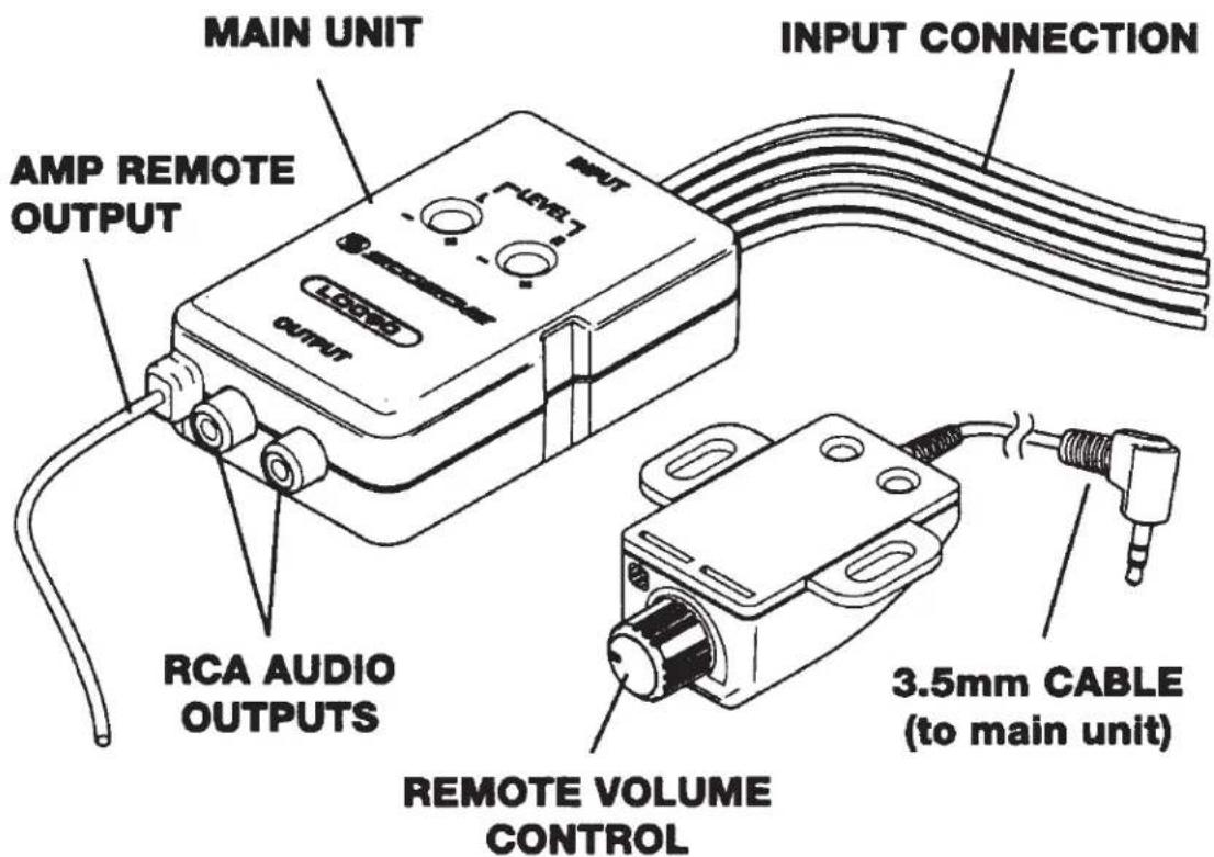
WIRING INSTRUCTIONS
TIPS: For easier installation, connections can be made at the rear speakers in many vehicles without the need to remove the stereo! The LOC90 adapter module will output a +12V remote output on the Blue/White wire when signal is detected from the car stereo's speaker wires. Wire colors on the LOC90 may differ from the wiring codes found on your car stereo/vehicle.
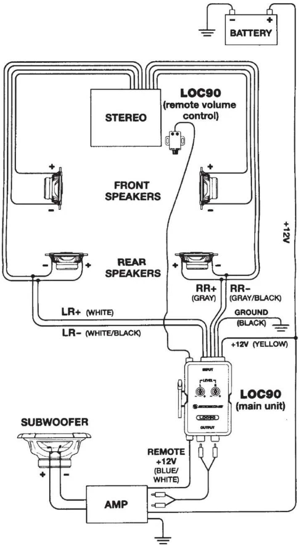
- Connect the black wire to chassis ground (vehicle metal).
- Connect the yellow wire to a +12V constant (continuous) power source. TIP: If amplifier is installed nearby, tap the yellow wire from the LOC90 into the amplifier's +12V battery terminal or wire.
- Connect the left speaker's +/- input wires to the white and white black input wires of the LOC90. This can be performed at the vehicle's speaker location or behind the stereo itself.
- Connect the right speaker's +/- input wires to the gray and gray/black input wires of the LOC90. This can be performed at the vehicle's speaker location or behind the stereo itself.
- Connect the blue/white wire to the amplifier's "remote turn-on" or "REM" input. Always refer to your amplifier's owner's manual for wiring details/functions of your particular amplifier (remote output: 500mA).
- Connect the RCA audio outputs of the LOC90 to the amplifier's inputs (RED = right channel, WHITE = left channel)
NOTE: Some mono (monaural) sub amplifiers may have only a single RCA input. You can choose either the left or right signal from the LOC90, but it is advisable to use a y-adapter to combine together for maximum signal level.
WIRING DIAGRAM
flowchart
graph TD
    A["STEREO"] --> B["LOC90 (remote volume control)"]
    C["FRONT SPEAKERS"] --> B
    D["REAR SPEAKERS"] --> B
    E["LR+ (WHITE)"] --> F["RR+ (GRAY)"]
    G["LR- (WHITE/BLACK)"] --> F
    H["SUBWOOFER"] --> I["AMP"]
    J["BATTERY"] --> K["+12V"]
    L["Ground (BLACK)"] --> M["+12V (YELLOW)"]
    N["OUTPUT"] --> O["LOG90 (main unit)"]
    P["REMOTE +12V (BLUE/WHITE)"] --> Q["AMP"]
    R["Ground"] --> S["+12V (YELLOW)"]
    T["AMP"] --> U["SubWOOFER"]
    V["Ground"] --> W["+12V (YELLOW)"]
    X["Ground"] --> Y["+12V (YELLOW)"]
    Z["Ground"] --> AA["+12V (YELLOW)"]
    AB["Ground"] --> AC["+12V (YELLOW)"]
    AD["Ground"] --> AE["+12V (YELLOW)"]
    AF["Ground"] --> AG["+12V (YELLOW)"]
    AH["Ground"] --> AI["+12V (YELLOW)"]
    AJ["Ground"] --> AK["+12V (YELLOW)"]
    AL["Ground"] --> AM["+12V (YELLOW)"]
    AN["Ground"] --> AO["+12V (YELLOW)"]
    AP["Ground"] --> AQ["+12V (YELLOW)"]
    AR["Ground"] --> AS["+12V (YELLOW)"]
    AT["Ground"] --> AU["+12V (YELLOW)"]
    AV["Ground"] --> AW["+12V (YELLOW)"]
    AX["Ground"] --> AY["+12V (YELLOW)"]
    AZ["Ground"] --> BA["+12V (YELLOW)"]
    BB["Ground"] --> BC["+12V (YELLOW)"]
    BD["Ground"] --> BE["+12V (YELLOW)"]
    BF["Ground"] --> BG["+12V (YELLOW)"]
    BH["Ground"] --> BI["+12V (YELLOW)"]
    BJ["Ground"] --> BK["+12V (YELLOW)"]
    BL["Ground"] --> BM["+12V (YELLOW)"]
    BN["Ground"] --> BO["+12V (YELLOW)"]
    BP["Ground"] --> BQ["+12V (YELLOW)"]
    BR["Ground"] --> BS["+12V (YELLOW)"]
    BT["Ground"] --> BU["+12V (YELLOW)"]
    BV["Ground"] --> BW["+12V (YELLOW)"]
    BX["Ground"] --> BY["+12V (YELLOW)"]
    CA["Ground"] --> CB["+12V (YELLOW)"]
    CC["Ground"] --> CD["+12V (YELLOW)"]
    CE["Ground"] --> CF["+12V (YELLOW)"]
    CG["Ground"] --> CH["+12V (YELLOW)"]
    CI["Ground"] --> CJ["+12V (YELLOW)"]
    CK["Ground"] --> CL["+12V (YELLOW)"]
    CM["Ground"] --> CN["+12V (YELLOW)"]
    CO["Ground"] --> CP["+12V (YELLOW)"]
    CS["Ground"] --> CT["+12V (YELLOW)"]
    CU["Ground"] --> CV["+12V (YELLOW)"]
    CW["Ground"] --> CX["+12V (YELLOW)"]
    CY["Ground"] --> CZ["+12V (YELLOW)"]
    DA["Ground"] --> DB["+12V (YELLOW)"]
    DC["Ground"] --> DE["+12V (YELLOW)"]
    DF["Ground"] --> DG["+12V (YELLOW)"]
    DH["Ground"] --> DI["+12V (YELLOW)"]
    DJ["Ground"] --> DE
    DK["Ground"] --> DE
    LE["BATTERY"] --> MD
    MD --> DN
    DN --> DD
    DD --> DP
    DP --> DR
    DR --> DV
    DV --> DW
    DW --> DX
    DX --> DB
    DB --> DU
    DU --> DV
    DV --> DW
    DW --> DX
    DX --> DV
    DV --> DW
    DW --> SX
    SX --> Y
    Y --> Z
    Z --> AA
    AA --> AB
    AB --> AC
    AC --> AD
    AD --> AE
    AE --> AF
    AF --> AG
    AG --> AH
    AH --> AI
    AI --> AJ
    AJ --> AK
    AK --> AL
    AL --> AM
    AM --> AN
    AN --> AO
    AO --> AP
    AP --> AQ
    AQ --> AR
    AR --> AS
    AS --> AT
    AT --> AU
    AU --> AV
    AV --> AW
WIRING COLOR CODES
NOTE: The wire colors on the LOC90 may differ from the wiring colors found on the car stereo / in vehicle. Always refer to the stereo owner's manual for wiring details/functions for your particular car stereo. The wire color codes used on the LOC90 conform to the standards set by the E.I.A. (Electronics Industry Association).
$$ \begin{array}{l} \text { White } = \text { Left front positive input (LF + ) } \ \text { White / black } = \text { Left front negative input (LF - ) } \ \text { Gray } = \text { Right front positive input } (\mathrm{RF} +) \ \text { Gray / black } = \text { Right front negative input (RF-)} \ \begin{array}{l} \text { Yellow } = + 1 2 \text { volt power input } \ \text {(constant battery power)} \end{array} \ \text { Black } = \text { Chassis ground (vehicle metal) } \ \text { Blue / white } = + 1 2 \mathrm{V} \text { remote output(amp turn - on) } \ \end{array} $$
REMOTE SUB/VOLUME CONTROL
The LOC90 includes on optional remote-mount volume control to attenuate/control the new AMP/SUB system level. Choose a location accessible to the driver, passenger or both. See Figure 1 on page 6 for suggested locations.
TIP: Check for obstructions at the chosen location before mounting/routing the volume control.
Recommended: Use the included adhesive strip for non-permanent mounting. Optional: For permanent mounting, use (2) small 14 " screws (not included).
REMOTE SUB/VOLUME CONTROL
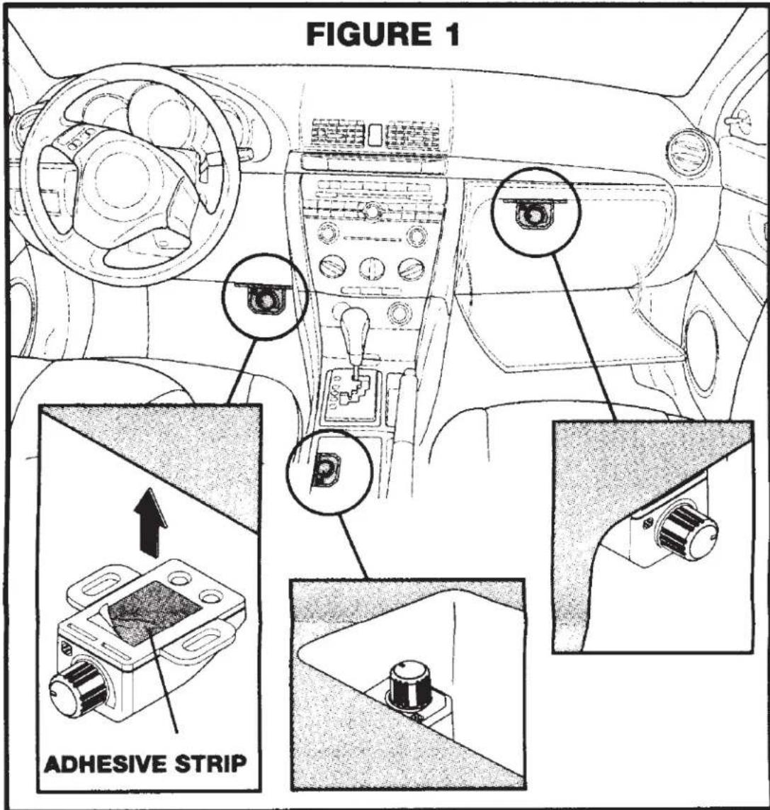
- Choose the desired location for the remote volume control (Figure 1).
- Route the control cable from the selected location to the LOC90 main unit.
- Plug the male 3.5mm control wire into the female 3.5mm input of the LOC90 module.
- Peel the backing strip from one side of the adhesive and attach to the remote volume control case. When ready to mount, peel away the remaining strip and press the unit to the mounting surface.
Optional: For additional support use 2 small screws (screws not included).
The LOC90 can output up to 4 volts, a slight adjustment can change the volume dramatically. The adjustment pots rotate one complete turn, do not over-turn or use too much pressure.
Adjust gains with caution. Too much volume or distortion can damage your hearing and the audio equipment.
-
Carefully break away the screwdriver tool from the side of the LOC90 case (Figure 2).
-
If using the remote volume control, ensure that it is connected to the main unit with its knob turned all the UP (Figure 3).
-
Use the included tool at the LOC90 module and turn both gain controls all the way down (counterclockwise until they stop - Figure 4).
-
Turn stereo on and adjust volume up to 34 (or just above loudest listening level)
-
Carefully turn up the left and right gain controls (turn clockwise) on the LOC90 until the sound is as loud as will ever need to be or near distortion (when sound becomes garbled, unclear, or breaks up).
-
Turn back each gain level very slightly from step #5 and then immediately turn down stereo volume.
-
If you hear a "hum" or excessive "hiss" sound between songs then the gain levels may still be adjusted too high.
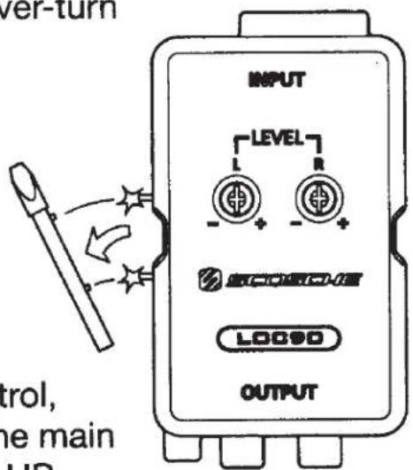
FIGURE 2
natural_image
Technical diagram of a mechanical component labeled 'FIGURE 3' (no other text or symbols)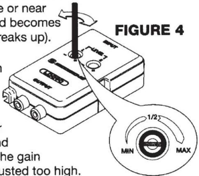
TROUBLESHOOTING
NO SOUND:
- Check and verify all electrical and signal connections.
- Speaker wire connections to LOC90 input
- Audio RCA cable connections from LOC90 output to amplifier.
- Check that amplifier is turning on when stereo is on.
- Verify remote turn-on output (blue/white wire) from LOC90 is connected to amplifier
- Verify that LOC90 is receiving +12V on yellow wire and black wire is connected to chassis ground.
Note: If all of the above conditions are met, it may be necessary to connect the amplifier's remote turn-on terminal/wire directly to the car stereo or ignition.
- Check gain adjustment levels on LOC90
- (If using remote volume control) check that the knob is not turned all the way down.
- If still no sound call tech support at 1-800-621-3695 x3.
LIMITED WARRANTY
Scosche Industries, Inc. warrants this product to be free from defects in material and workmanship for a period of 90 days from date of purchase. All Scosche products are sold with the understanding that the purchaser has independently determined the suitability of such products. This warranty does not cover any expenses incurred in the removal and reinstallation of the product. This warranty is offered to the original purchaser of the product only. This warranty does not apply to the product which has been damaged by accident, or which has been misued, altered, or installed improperly.
If the product should prove defective within the warranty period, return the product with sales slip, postage prepaid to Scosche Industries, Inc.
Your dated sales slip/proof of purchase will establish your warranty eligibility. Scosche, at its option, will replace or repair the product free of charge and return the product to you postage paid.
In no event shall Scosche be responsible for claims beyond the replacement value of the defective product or in any way be held liable or responsible for consequential or incidental damages.
No express warranties and no implied warranties, whether for fitness or any particular use, or otherwise, except as set forth above (which is made expressly in lieu of all other warranties) shall apply to products sold by Scosche. No waiver, alteration, addition, or modification of the foregoing conditions shall be valid unless made in writing and signed by an executive officer of Scosche Industries, Inc.
No salesperson, representative, or agent of Scosche is authorized to give any guarantee, warranty, or make any representation contrary to the above.
Line output Converter
2-Channel AdJUSTABLE
2-Channel Adjustable
Line Output Converter
LOC90
Optimized for Subwoofer System Upgrades
- Converts
Speaker Level to RCA Output
- Includes Mountable
Remote Level Control
- Provides +12V
Remote Output
530LOC90 4/14
Tech Support: 1,800 621 3695 xkl 3

scosche.com
Custom manufactured in China
Designed and engrossed by scoring in CA USA
©2014 Stockholm is a registered trademark of Soccurie Industries, Inc.

SCOSCHE
FEATURES
- Converts 2-channel Speaker Level Input to RCA Line Level with up to 4V RMS Output
• Signal Sensing +12V Remote Output (requires power/ground connection) - Includes Mountable Remote Level Control with 17 ft. Cable
• Independent L/R Channel Level Adjustments - Accepts High Power Input up to 50W/CH RMS
Brand : Scosche
Model : LOC90
Category : Audio/video converter