HS-3200 - Video recorder DataVideo - Free user manual and instructions
Find the device manual for free HS-3200 DataVideo in PDF.


| Product Type | HD 12-Channel Portable Video Streaming Studio |
| Video Format | 1080p 50/59.94/60 Hz, 1080i 50/59.94/60 Hz, 720p 50/59.94/60 Hz |
| Video Inputs | 8 x SDI (Level A/B) + 4 x HDMI |
| Video Outputs | 5 x SDI (Level A) assignable (Multiview, PGM, PVW, etc.) + 1 x HDMI assignable + 3 x HDMI (Program only) |
| Analog Audio Inputs | 4 x Balanced XLR |
| Analog Audio Outputs | 2 x Balanced XLR |
| Upstream Keyers | 4 (Chroma, Luma, Linear) |
| Downstream Keyers | 2 (Linear & Luma) |
| Picture-in-Picture | 8 windows (4 from keyers, 4 from Flex sources) |
| Built-in Monitor | 17.3" HD TFT LED Backlit, 1920x1080 pixels |
| Streaming Video Encoder | H.264/AVC, Main/High Profile, bitrate up to 10 Mbps |
| Streaming Protocols | RTMP(S), RTSP, TS, HLS, SRT |
| Recording Media | SD card (Class 10 or above) |
| Recording File Format | MP4 |
| Dimensions (L x W x H) | 455 x 355 x 134 mm |
| Weight | 8.1 kg (17.8 lbs) |
| Power Supply | DC 12V, 11A |
| Operating Temperature | 0°C to 40°C |
| Software | Switcher Image Import/Export software, CG-200 Title Creator (free download) |
| Special Features | 4 chroma keyers, 9 stinger transitions, built-in TC-200 CG interface, 12x9 matrix seamless switch |
Frequently Asked Questions - HS-3200 DataVideo
User questions about HS-3200 DataVideo
0 question about this device. Answer the ones you know or ask your own.
Ask a new question about this device
Download the instructions for your Video recorder in PDF format for free! Find your manual HS-3200 - DataVideo and take your electronic device back in hand. On this page are published all the documents necessary for the use of your device. HS-3200 by DataVideo.
USER MANUAL HS-3200 DataVideo
natural_image
Line drawing of an open data viewer device with ports and connectors (no text or symbols)HD 12-Channel Portable
Video Streaming Studio
HS-3200
Instruction Manual
Table of Contents
FCC COMPLIANCE STATEMENT....7
WARNINGS AND PRECAUTIONS....7
WARRANTY 8
STANDARD WARRANTY 8
THREE YEAR WARRANTY....9
DISPOSAL 9
CHAPTER 1 INTRODUCTION ...... 10
1.1 SYSTEM ARCHITECTURE....12
1.2 REAR PANEL OVERVIEW 13
1.3 CONTROL PANEL OVERVIEW....14
1.4 CONNECTING THE POWER SUPPLY 15
CHAPTER 2 PREPARATION....16
2.1 CONNECTING DEVICES....16
Connecting the Video and Audio Input Devices 16
When linking via tally connection....17
Connecting the Video and Audio Output Devices 17
Connecting to a Network 18
2.2 MULTI VIEW 18
CHAPTER 3 NETWORK AND SOFTWARE SETUP FOR SWITCHER....19
3.1 STATIC IP CONFIGURATION....19
3.2 DHCP MODE....20
3.3 OPEN SWITCHER IMAGE IMPORT/EXPORT SOFTWARE 22
Home 23
User 24
Still....25
Clip....26
Logo....27
Ani-Logo 28
Setup 29
CHAPTER 4 OSD MENU 30
4.1 START 38
Transition 39
Type....39
Wipe Effects 39
WIPE Border 39
Position....40
Matte 40
4.2 KEYER....40
Keyer 40
Keyer Control....41
Key Source 42
Fill Source 42
Invert 43
Mask....43
4.3 CHROMA....43
Keyer 44
Key Source 44
Key Tie 44
CK Setup 45
Mask....46
4.4 P-IN-P 46
Keyer 47
Position....47
Fine....48
Border......48
Shade Matte (Dual Color Border)....48
Crop 50
4.5 FLEX SRC 50
Flex Screen 50
Keyer 51
Flex Preset....53
4.6 INPUTS....54
Input 55
Proc Amp....56
Audio 56
Crosspoint 56
Audio XPT 57
4.7 OUTPUTS....57
Outputs 57
Multiviewer....58
Tally Mode....59
GPI Out....59
4.8 AUDIO 60
Audio 60
PGM Audio 60
Analog Out 61
4.9 FILES....61
User Mems 61
Still....62
Clip....64
Logo....66
Ani Logo 67
4.10 SETUP....68
Standard....68
Genlock....69
OutConv....69
Menu Mode....69
Menu Preference....69
Auto Save 70
Factory Default....70
Language....70
Network....70
Software....70
CHAPTER 5 BASIC OPERATION....72
5.1 VIDEO SWITCHING....72
Program and Preset rows 72
Black and MATTE View 72
Flex Output....73
Still button....73
5.2 TRANSITIONS....73
WIPE Selection MENU 75
REV Button 76
5.3 MANAGING STILL PICTURES 76
Grabbing & Saving a Still to Memory....76
Loading an existing Still from Memory 77
Deleting a saved Still from Memory....77
FS – Frame Store Button 77
Import Still Images from PC 78
5.4 PERFORMING A STINGER TRANSITION....81
Loading a Clip from Memory 81
Importing the Clip for Stinger Transition Effect from PC 82
How to Create the PNG Sequence for Stinger Transition Effect 83
Important things to note while creating Stinger Transition Effects 89
5.5 ENABLING STILL LOGO....90
Loading an existing Logo from Memory 90
Importing Still Logo from PC 91
5.6 ENABLING LOGO ANIMATION 93
Loading an existing Ani-Logo from Memory....93
Importing Animated Logo from PC 93
CHAPTER 6 ADVANCED OPERATION....96
6.1 PICTURE-IN-PICTURE AND DOWNSTREAM KEY 97
Picture-In-Picture 97
Character Generator....99
6.2 PLACING TEXT ON THE VIDEO USING LUMA KEY 100
6.3 INSERTION OF PEOPLE ONTO BACKGROUNDS (CHROMA KEY)....102
6.4 DISPLAYING A VARIETY OF SOURCES AT THE SAME TIME....105
Basic Flex™ Output (Four PIP Windows)....105
Simultaneously Enabling up to Eight PIP Windows 109
6.5 SHORTCUT KEYS TO ASSIGNING OUTPUT SOURCES....111
CHAPTER 7 VIDEO STREAMING AND RECORDING....114
7.1 STREAMING NETWORK CONNECTION AND DEVICE SEARCH....114
Connecting to a DHCP Network (DHCP Mode) 114
Connecting to a NON-DHCP Network (Static IP)....115
Troubleshooting the Network Connection....115
7.2 WEB USER INTERFACE....119
Status 119
Operation Mode....121
Storage....131
CG....132
System....133
File Repair....138
7.3 OPERATIONS....139
Video Streaming....139
Text Overlay Video....147
7.4 STREAM AND RECORD BUTTONS 148
Two Button Model 148
Four Button Model....150
7.5 RESTORING FACTORY DEFAULTS....154
7.6 FIRMWARE UPDATE....154
CHAPTER 8 MONITOR OSD MENU 155
8.1 MAIN ADJUST 156
8.2 COLOR....156
8.3 INFORMATION....156
8.4 SPECIAL FUNCTION 157
8.5 FACTORY RESET 157
CHAPTER 9 APPENDICES....158
APPENDIX 1 TALLY OUTPUTS....158
APPENDIX 2 GPI / GPO CONNECTIONS ....160
APPENDIX 3 RECOMMENDED SD CARDS....161
APPENDIX 4 FIRMWARE UPDATE....163
Switcher....163
Video Streaming Server....164
APPENDIX 5 FREQUENTLY-ASKED QUESTIONS....166
APPENDIX 6 DIMENSIONS....167
APPENDIX 7 SPECIFICATIONS ....168
SERVICE AND SUPPORT 172
Disclaimer of Product & Services
The information offered in this instruction manual is intended as a guide only. At all times, Datavideo Technologies will try to give correct, complete and suitable information. However, Datavideo Technologies cannot exclude that some information in this manual, from time to time, may not be correct or may be incomplete. This manual may contain typing errors, omissions or incorrect information. Datavideo Technologies always recommend that you double check the information in this document for accuracy before making any purchase decision or using the product. Datavideo Technologies is not responsible for any omissions or errors, or for any subsequent loss or damage caused by using the information contained within this manual. Further advice on the content of this manual or on the product can be obtained by contacting your local Datavideo Office or dealer.
FCC Compliance Statement
This device complies with part 15 of the FCC rules. Operation is subject to the following two conditions:
(1) This device may not cause harmful interference, and
(2) This device must accept any interference received, including interference that may cause undesired operation.
Warnings and Precautions

-
Read all of these warnings and save them for later reference.
-
Follow all warnings and instructions marked on this unit.
-
Unplug this unit from the wall outlet before cleaning. Do not use liquid or aerosol cleaners. Use a damp cloth for cleaning.
-
Do not use this unit in or near water.
-
Do not place this unit on an unstable cart, stand, or table. The unit may fall, causing serious damage.
-
Slots and openings on the cabinet top, back, and bottom are provided for ventilation. To ensure safe and reliable operation of this unit, and to protect it from overheating, do not block or cover these openings. Do not place this unit on a bed, sofa, rug, or similar surface, as the ventilation openings on the bottom of the cabinet will be blocked. This unit should never be placed near or over a heat register or radiator. This unit should not be placed in a built-in installation unless proper ventilation is provided.
-
This product should only be operated from the type of power source indicated on the marking label of the AC adapter. If you are not sure of the type of power available, consult your Datavideo dealer or your local power company.
-
Do not allow anything to rest on the power cord. Do not locate this unit where the power cord will be walked on, rolled over, or otherwise stressed.
-
If an extension cord must be used with this unit, make sure that the total of the ampere ratings on the products plugged into the extension cord do not exceed the extension cord rating.
-
Make sure that the total amperes of all the units that are plugged into a single wall outlet do not exceed 15 amperes.
-
Never push objects of any kind into this unit through the cabinet ventilation slots, as they may touch dangerous voltage points or short out parts that could result in risk of fire or electric shock. Never spill liquid of any kind onto or into this unit.
-
Except as specifically explained elsewhere in this manual, do not attempt to service this product yourself. Opening or removing covers that are marked "Do Not Remove" may expose you to dangerous voltage points or other risks, and will void your warranty. Refer all service issues to qualified service personnel.
-
Unplug this product from the wall outlet and refer to qualified service personnel under the following conditions:
a. When the power cord is damaged or frayed;
b. When liquid has spilled into the unit;
c. When the product has been exposed to rain or water;
d. When the product does not operate normally under normal operating conditions. Adjust only those controls that are covered by the operating instructions in this manual; improper adjustment of other controls may result in damage to the unit and may often require extensive work by a qualified technician to restore the unit to normal operation;
e. When the product has been dropped or the cabinet has been damaged;
f. When the product exhibits a distinct change in performance, indicating a need for service.
Warranty
Standard Warranty
- Datavideo equipment is guaranteed against any manufacturing defects for one year from the date of purchase.
- The original purchase invoice or other documentary evidence should be supplied at the time of any request for repair under warranty.
- The product warranty period beings on the purchase date. If the purchase date is unknown, the product warranty period begins on the thirtieth day after shipment from a Datavideo office.
- All non-Datavideo manufactured products (product without Datavideo logo) have only one year warranty from the date of purchase.
- Damage caused by accident, misuse, unauthorized repairs, sand, grit or water is not covered under warranty.
- Viruses and malware infections on the computer systems are not covered under warranty.
- Any errors that are caused by unauthorized third-party software installations, which are not required by our computer systems, are not covered under warranty.
• All mail or transportation costs including insurance are at the expense of the owner.
- All other claims of any nature are not covered.
- All accessories including headphones, cables, batteries, metal parts, housing, cable reel and consumable parts are not covered under warranty.
- Warranty only valid in the country or region of purchase.
- Your statutory rights are not affected.
Three Year Warranty
- All Datavideo products purchased after July 1st, 2017 qualify for a free two years extension to the standard warranty, providing the product is registered with Datavideo within 30 days of purchase.

- Certain parts with limited lifetime expectancy such as LCD panels, DVD drives, Hard Drive, Solid State Drive, SD Card, USB Thumb Drive, Lighting, Non-PCIe Card and third party provided PC components are covered for 1 year.
- The three-year warranty must be registered on Datavideo's official website or with your local Datavideo office or one of its authorized distributors within 30 days of purchase.
Disposal
natural_image
Symbol of a trash bin crossed with no text or labels, representing waste sorting or disposal (no text present)For EU Customers only - WEEE Marking
This symbol on the product or on its packaging indicates that this product must not be disposed of with your other household waste. Instead, it is your responsibility to dispose of your waste equipment by handing it over to a designated collection point for the recycling of waste electrical and electronic equipment. The separate collection and recycling of your
waste equipment at the time of disposal will help to conserve natural resources and ensure that it is recycled in a manner that protects human health and the environment. For more information about where you can drop off your waste equipment for recycling, please contact your local city office, your household waste disposal service or the shop where you purchased the product.

CE Marking is the symbol as shown on the left of this page. The letters "CE" are the abbreviation of French phrase "Conformité Européenne" which literally means "European Conformity". The term initially used was "EC Mark" and it was officially replaced by "CE Marking" in the Directive
93/68/EEC in 1993. "CE Marking" is now used in all EU official documents.
Chapter 1 Introduction
HS-3200 is a 12 channel professional mobile hand carry switcher with real Full 1080p/60 (3G) High Definition support, featuring 12 digital inputs including 8 SDI and 4 HDMI inputs with embedded audio, 5 SDI and 1 HDMI outputs for connecting HD recorder, external monitors and etc.
HS-3200 is a lightweight, portable and powerful featured mobile studio solution which is designed for live events and TV programs that need to mix a variety of video and audio sources. HS-3200 is also a great value solution for the worship, education and AV markets.
The HS-3200 also has powerful, easy-to-use effects, including Chroma / Luma Key, DSK, PIP, Wipe Generator, Still stores, logo insertion and built-in title overlay system for the entry level Datavideo CG.
Advanced features include a 17.3-inch Full HD 1080p video monitor, which displays the Multi-view. The Multi-view displays all video input sources, preview video and program video.
In addition, the HS-3200 offers an easy-to-use video streaming and recording device for professional video producers who need to simultaneously stream a live event and record the master quality version for post-event editing.
Major features
• One machine for 12 channel 1080p video switching, recording and streaming
- Broadcast quality H.264 media streaming over RTMP(S), RTSP, TS, HLS and SRT for sending videos to broadcast platforms like Facebook, Youtube
• Record on SD Card for post-production
• Original 1080p (3G) operation
- Flexible combinations of 4 USKs and 2 DSKs
- Up to 8 PIP windows with four showing FLEX sources
• Supports 4 broadcast quality chromakeyers and
• virtual studio background images
• 17 stinger transitions
Summary of all features
• 12 Total Video input interfaces: 8 x SDI (Level A/B) + 4 x HDMI
- 9 Video Output: 5 x SDI (Level A) + 1 HDMI + 3 x HDMI (Program OUT only)
• 4 Upstream Keyers, supporting Chroma key & Linear / Luma key
• 4 PIP (assignable to any of keyers)
- DSK, supporting Linear & Luma Key Modes
- Logo insertion (Animation logo, X/Y size)
- Wipe, Mix, DVE, Cut and Stinger Transitions
• 32 Wipe patterns including Circle & Heart, and Borders & Softness Control
- Clip player (150 Frames) Stinger Transitions function
- Any Input (1-12) can be used as a Frame store (Stills Store)
• Video and Audio Crosspoint Assignments (XPT)
• 4 x XLR Analogue Audio Inputs
• 2 x XLR De-embedded Analogue Audio Outputs - Tally output
• USB Port for FW upgrade
1.1 System Architecture
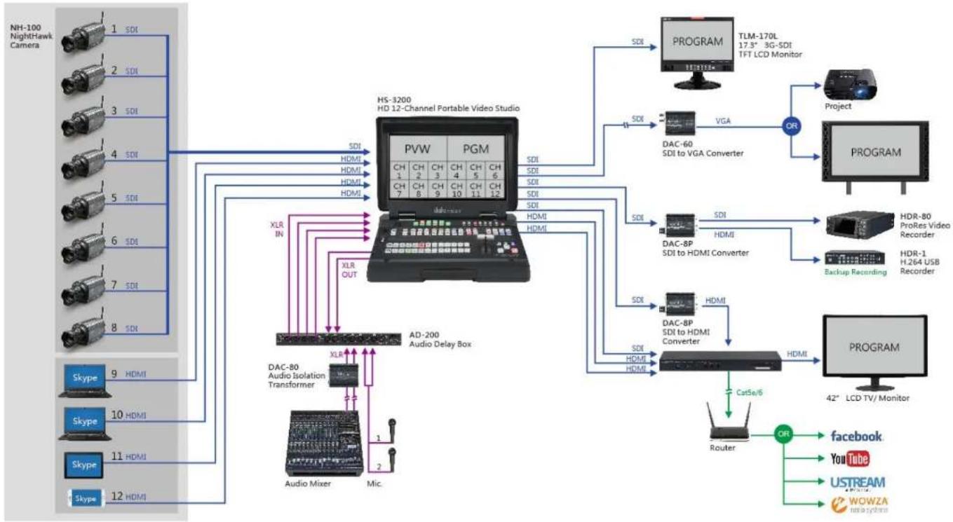
flowchart
graph TD
    A["NH-100 NightHawk Camera"] -->|1 SDI| B["HS-3200 HD 12-Channel Portable Video Studio"]
    A -->|2 SDI| B
    A -->|3 SDI| B
    A -->|4 SDI| B
    A -->|5 SDI| B
    A -->|6 SDI| B
    A -->|7 SDI| B
    A -->|8 SDI| B
    A -->|9 HDMI| B
    A -->|10 HDMI| B
    A -->|11 HDMI| B
    A -->|12 HDMI| B
    B --> C["AD-200 Audio Delay Box"]
    C --> D["DAC-80 Audio Isolation Transformer"]
    C --> E["Audio Mixer"]
    C --> F["Mic."]
    C --> G["XLR IN"]
    C --> H["XLR OUT"]
    C --> I["SDI"]
    C --> J["SDI"]
    C --> K["SDI"]
    C --> L["SDI"]
    C --> M["SDI"]
    C --> N["SDI"]
    C --> O["SDI"]
    C --> P["SDI"]
    C --> Q["SDI"]
    C --> R["SDI"]
    C --> S["SDI"]
    C --> T["SDI"]
    C --> U["SDI"]
    C --> V["SDI"]
    C --> W["SDI"]
    C --> X["SDI"]
    C --> Y["SDI"]
    C --> Z["SDI"]
    C --> AA["SDI"]
    C --> AB["SDI"]
    C --> AC["SDI"]
    C --> AD["SDI"]
    C --> AE["SDI"]
    C --> AF["SDI"]
    C --> AG["SDI"]
    C --> AH["SDI"]
    C --> AI["SDI"]
    C --> AJ["SDI"]
    C --> AK["SDI"]
    C --> AL["SDI"]
    C --> AM["SDI"]
    C --> AN["SDI"]
    C --> AO["SDI"]
    C --> AP["SDI"]
    C --> AQ["SDI"]
    C --> AR["SDI"]
    C --> AS["SDI"]
    C --> AT["SDI"]
    C --> AU["SDI"]
    C --> AV["SDI"]
    C --> AW["SDI"]
    C --> AX["SDI"]
    C --> AY["SDI"]
    C --> AZ["SDI"]
    C --> BA["SDI"]
    C --> BB["SDI"]
    C --> BC["SDI"]
    C --> BD["SDI"]
    C --> BE["SDI"]
    C --> BF["SDI"]
    C --> BG["SDI"]
    C --> BH["SDI"]
    C --> BI["SDI"]
    C --> BJ["SDI"]
    C --> BK["SDI"]
    C --> BL["SDI"]
    C --> BM["SDI"]
    C --> BN["SDI"]
    C --> BO["SDI"]
    C --> BP["SDI"]
    C --> BQ["SDI"]
    C --> BR["SDI"]
    C --> BS["SDI"]
    C --> BT["SDI"]
    C --> BU["SDI"]
    C --> BV["SDI"]
    C --> BW["SDI"]
    C --> BX["SDI"]
    C --> BY["SDI"]
    C --> BZ["SDI"]
    C --> CA["SDI"]
    C --> CB["SDI"]
    C --> CC["SDI"]
    C --> CD["SDI"]
    C --> CE["SDI"]
    C --> CF["SDI"]
    C --> CG["SDI"]
    C --> CH["SDI"]
    C --> CI["SDI"]
    C --> CJ["SDI"]
    C --> CK["SDI"]
    C --> CL["SDI"]
    C --> CM["SDI"]
    C --> CN["SDI"]
    C --> CO["SDI"]
    C --> CP["SDI"]
    C --> CS["SDI"]
    C --> CT["SDI"]
    C --> CU["SDI"]
    C --> CV["SDI"]
    C --> CW["SDI"]
    C --> CX["SDI"]
    C --> CY["SDI"]
    C --> CZ["SDI"]
    C --> DA["SDI"]
    C --> DB["SDI"]
    C --> DC["SDI"]
    C --> DD["SDI"]
    C --> DE["SDI"]
    C --> DF["SDI"]
    C --> DG["SDI"]
    C --> DH["SDI"]
    C --> DI["SDI"]
    C --> DJ["SDI"]
    C --> DK["SDI"]
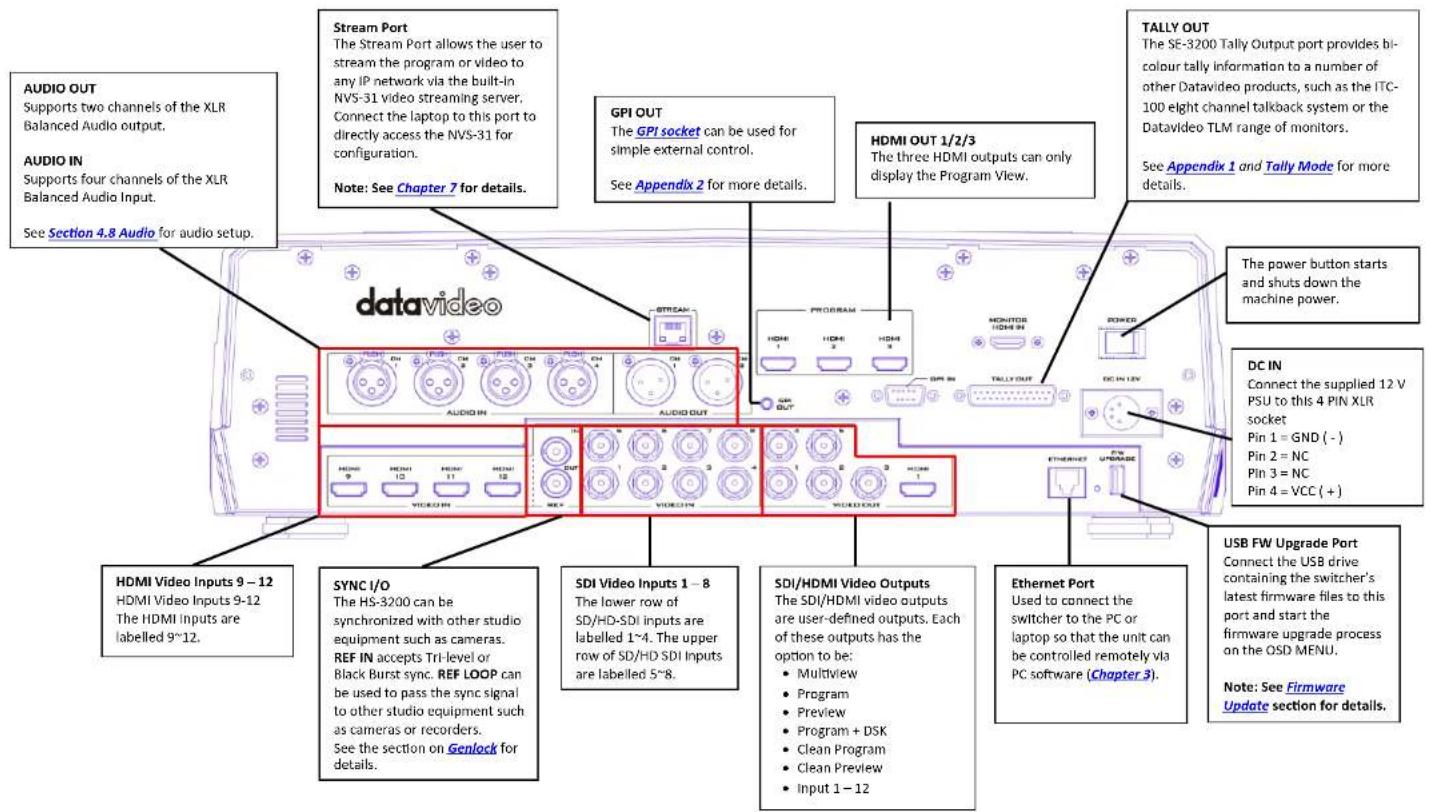
1.2 Rear Panel Overview
1.3 Control Panel Overview
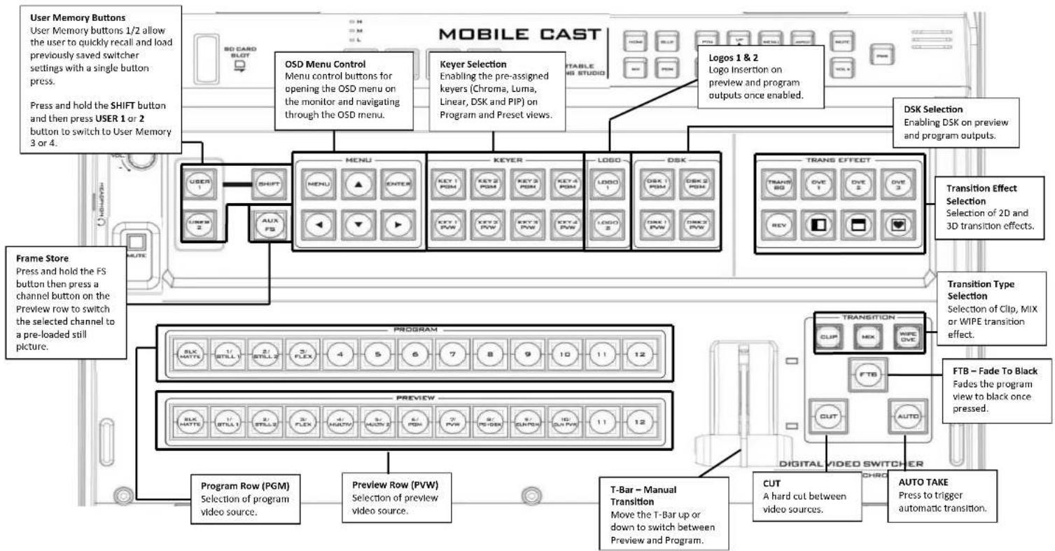
Perform video switching and other relevant controls on the Control Panel.
flowchart
graph TD
    A["User Memory Buttons"] --> B["OSD Menu Control"]
    B --> C["Keyer Selection"]
    C --> D["LOGO"]
    D --> E["DSK"]
    E --> F["TRANS EFFECT"]
    F --> G["Transition Effect Selection"]
    G --> H["Transition Type Selection"]
    H --> I["FTB - Fade To Black"]
    I --> J["DIGITAL VIDEO SWITCHER"]
    J --> K["AUTO TAKE"]

    subgraph Mobile_Cast
        L["User Memory buttons 1/2 allow user to quickly recall and load previously saved switcher settings with a single button press.<br>Press and hold the SHIFT button and then press USER 1 or 2 button to switch to User Memory 3 or 4."]
    end

    subgraph Keyer
        M["Menu control buttons for opening the OSD menu on the monitor and navigating through the OSD menu."]
    end

    subgraph DSK
        N["Logo Insertion on preview and program outputs once enabled."]
        O["Dialog 1 & 2 Logo Insertion on preview and program outputs once enabled."]
    end

    subgraph Transition
        P["TRANS EFFECT Selection"]
        Q["Transition Type Selection"]
        R["FTB - Fade To Black"]
        S["Digital Video Switcher"]
    end

    subgraph Preview
        T["Program Row (PGM) Selection of program video source."]
        U["Preview Row (PVW) Selection of preview video source."]
        V["T-Bar - Manual Transition<br>Move the T-Bar up or down to switch between Preview and Program."]
        W["CUT<br>A hard cut between video sources."]
        X["AUTO TAKE<br>Press to trigger automatic transition."]
    end

    subgraph Frame
    Y["Frame Store<br>Press and hold the FS button then press a channel button on the Preview row to switch to a pre-loaded still picture."]
    end
1.4 Connecting the Power Supply
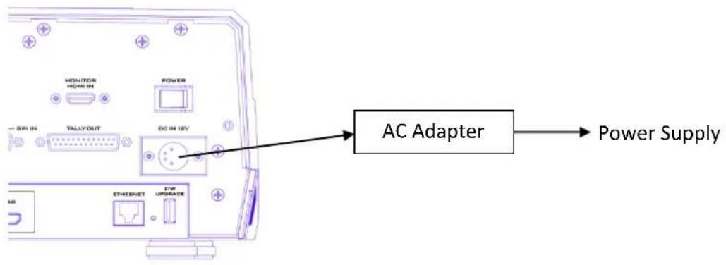
Connect the DC output plug of the supplied AC adapter to the DC IN 12V connector on the rear of the switcher and then connect the AC adapter to a power supply.
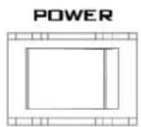
To start, turn ON the power switch.
To shut off the machine, simply turn OFF the power switch.
Chapter 2 Preparation
In this chapter, we will describe various essential devices to be connected to the switcher in order to complete the system setup. If you possess the skills for setting up the production system, feel free to skip this chapter and proceed to Chapter 5: Basic Operation.
2.1 Connecting Devices
Connecting the Video and Audio Input Devices
Connect cameras, computers and other video input devices to the video input connectors on the rear of the unit and connect an audio mixer to audio input connectors.
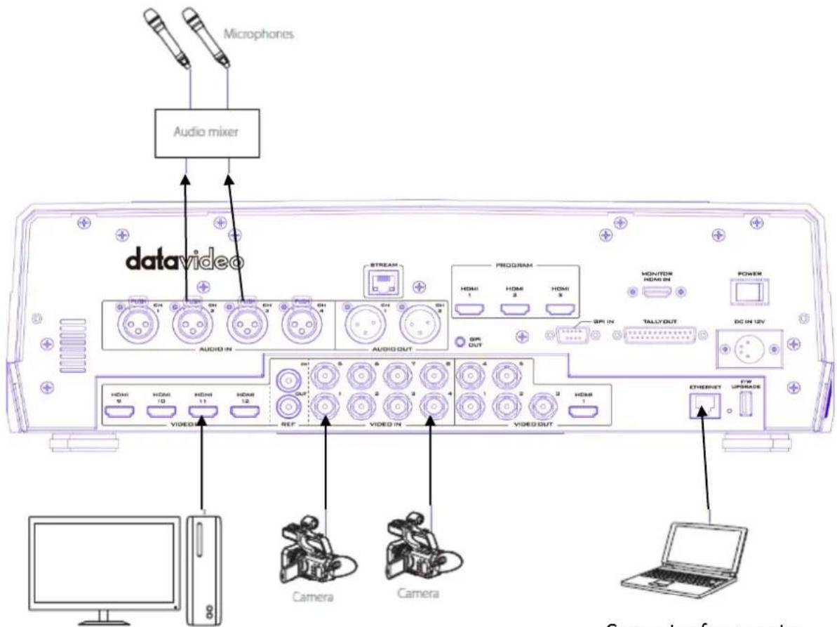
Computer for text input
Computer for remote control of the switcher
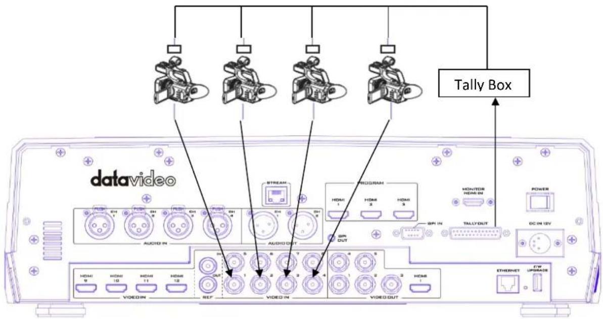
When linking via tally connection
Connect the switcher's tally connector to the tally connector on a commercially available tally box.
Connecting the Video and Audio Output Devices
Connect projectors, large displays and other video output devices to the video output connectors on the rear of the switcher.
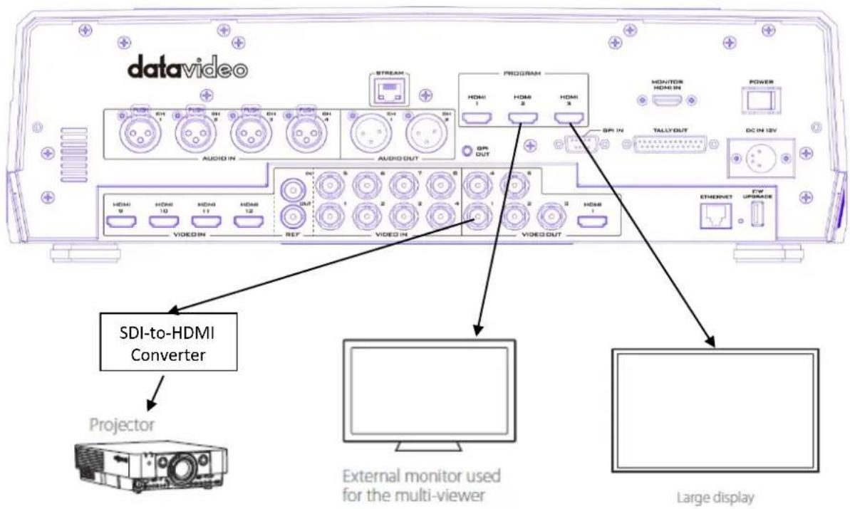
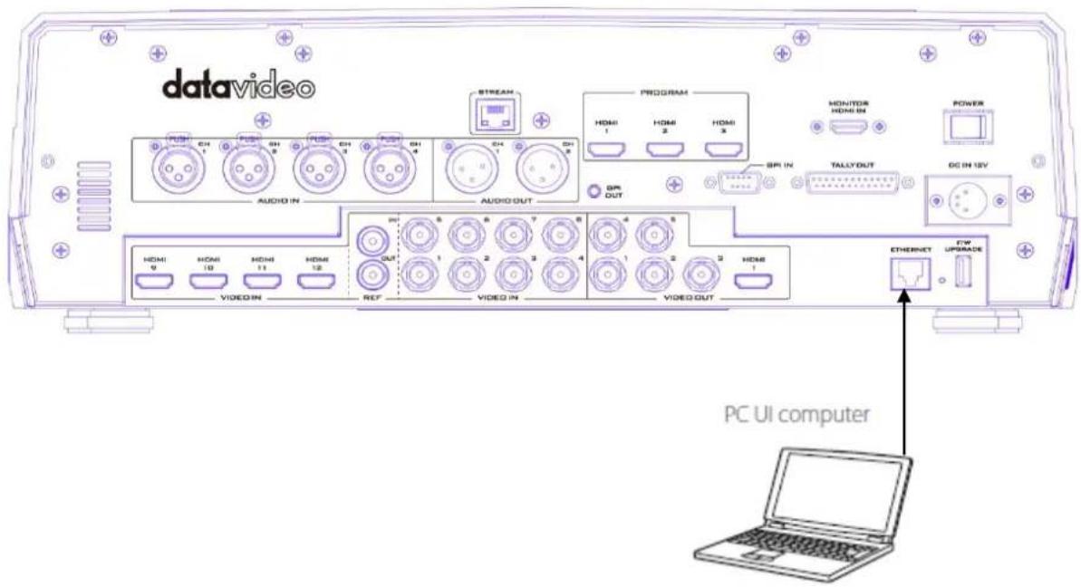
Connecting to a Network
Use the Ethernet Port to connect the switcher to the PC with the Image Import/Export Software installed.
For details on the Switcher Image Import/Export Software, see Chapter 3.
2.2 Multi View
The HS-3200 Multi view output can be supplied from the HDMI or SDI outputs, see Chapter 4 (4.7) for configuring the outputs. The Multi view shows monitoring images for Preview (PVW), Program (PGM) and Inputs 1\~12. The Multi view can also show audio level bars overlaid on the Program image. This confirms the analogue XLR audio input is being received and embedded to the selected Program output(s).
HS-3200 Multi-view is supplied from the HDMI connection(s) on the rear panel and available across multiple HDMI monitors (not supplied). Since a variety of multi-image layouts is available, these HDMI outputs can be used to monitor video and audio in a number of different configurations. The layout of the multi view can also be changed. The sources can be swapped around using the cross point section of the Inputs menu. For each setup, embedded audio level indication is available on the Preview and Program windows.
See Multiviewer in Section 4.7 for nine different multi-view layouts available on the HS-3200.
Note: A Red tally indication box will be shown around the sources selected for Program OUT and these selected sources should be displayed at the switcher's selected Program output(s). A Green tally indication box is shown around the sources selected for Preview. These are the next image sources to be mixed to, wiped in or cut to the Program OUT depending on the user's preference.
Chapter 3 Network and Software Setup for Switcher
The Ethernet port on the back panel of the HS-3200 allows the user to import still images, clips for stinger transition, still logos, animated logos or user memories using the Switcher Image Import/Export software. This chapter discusses direct connection between the HS-3200 and your Windows computer as well as the remote setup in detail. Please download the Switcher Image Import/Export software to your PC or laptop from the product page (https://www.datavideo.com/tw/product/HS-3200) before using this feature.
Section 3.1 discusses how you can establish direct connection between the HS-3200 and a Windows computer. In Section 3.2, we will show you how to access the HS-3200 remotely on your PC or laptop with the Switcher Image Import/Export software.
3.1 Static IP Configuration
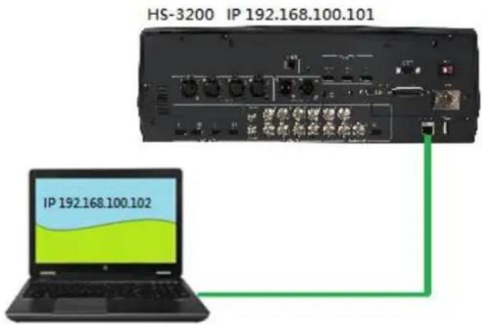
When new from the factory the HS-3200 will initially have a static IP address of 192.168.100.101. The unit can be directly connected to a Windows-based computer using an RJ-45 ethernet cable. The following set up should allow you to initially configure the unit's static IP settings.
System requirements and setup are provided as follows:
• An RJ-45 Ethernet cable.
• Windows 7/8/10 laptop or PC.
- The Datavideo Switcher Image Import/Export software.

Switcherlm agelmEx_v 0.0.3
Instructions
- First physically connect the HS-3200 to a Windows computer using an RJ-45 Ethernet cable.
- Turn on the Windows computer and set it to static IP setup within the Windows Network and Sharing Centre. In our example, the computer is given the following IP settings so that the computer matches the same IP range as the switcher.
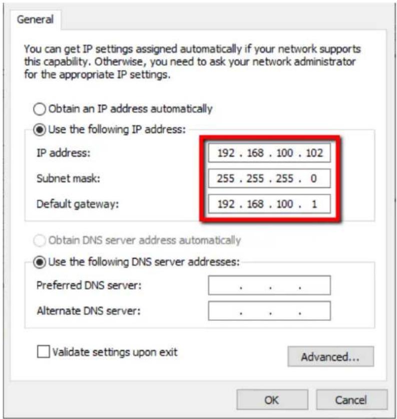
- Now open the Switcher Image Import/Export software to establish connection with the switcher.
Tip: You can also modify the switcher's IP address on the OSD menu such that it matches the network IP range or the IP assigned to your PC. See the Network Section for details. This is also the place where you will be able to check or reset your device IP address.
Note: After changing your network settings, always reboot your switcher for the new settings to become effective.
3.2 DHCP Mode
The computer software can also access the HS-3200 over an existing TCP/IP LAN type network. In order to initially set up the HS-3200, you may need the assistance of your local I.T. specialist to help with the network settings. To help guide you, we have included a quick network setup guide as well as a simplified network setup example below; further advice may be available through your dealer locally or your Datavideo regional office.
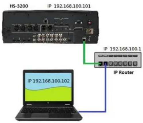
To create this simple dedicated HS-3200 IP network you will need:
- An IP router which can assign/give IP addresses.
- Two RJ-45 patch leads.
• Windows 7/8/10 laptop or PC. - The IP router Administrator login and password.
• The Datavideo Switcher Image Import/Export software.

SwitcherIm agelmEx_v 0.0.3
Instructions
- First connect the router to the HS-3200 and the Windows computer using two RJ-45 patch leads.
- Turn on the Windows computer and set it to DHCP setup within the Windows Network and Sharing Centre.
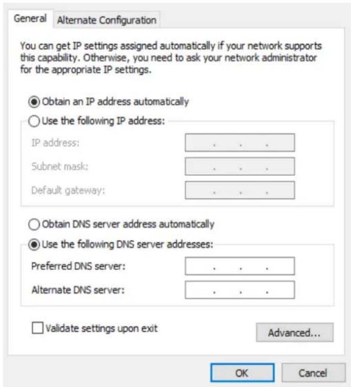
- Press the MENU button on the HS-3200 control panel to open the OSD menu on the connected Multiview monitor. Open the OSD menu → Setup → Network and then change the Addr Mode to DHCP from the default Static IP. Move to the SAVE option and press the ENTER button to save new settings.
- Reboot the HS-3200 and after the machine is rebooted, open the Network sub menu by following the instructions outlined in the previous step. The IP Addr option should show an IP address assigned randomly by the router thus having the same IP range as the router. If you see an IP address of 0.0.0.0 in the IP Addr field, it is likely that the router requires longer time to assign an IP address to the connected devices. Close the Network sub menu and reopen after 30-60 seconds, you should be able to see the newly assigned IP address. If problems still exist, contact any IT specialists for assistance.
3.3 Open Switcher Image Import/Export Software
After configuring your connection mode, download and unzip the Switcher Image Import/Export software then in the unzipped folder, double click the software icon to open the program.
The Switcher Image Import/Export software has a built-in IP finder, which is designed for PC with multiple Ethernet cards or DHCP network environment. Upon launch of the Switcher Image Import/Export software, you will be prompted to select one Ethernet Interface Card. Please note that the IP finder can only find devices connected to the same network as the PC.
![Select Network Interface for S... Network Interfaces: [192.168.100.102] Ethernet OK Cancel](/content/2026/05/950367/images/a2ae8fc713214e4627a124ebeec376fca27f7cf918f6620aabaafbcb4c0b0a30.jpg)
Once selected, click OK to start the scanning process.
Note: Please make sure the selected interface card is on the same network as the HS-3200 device.
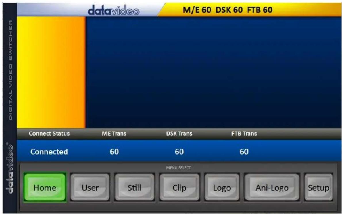
Once the HS-3200 device is found, the software will connect with the switcher over the IP set up described in the previous section. If the connection is successfully established, on the software user interface as shown in the diagram below, the Connect Status will show "Connected" (will display Not Connected if disconnected).
Brief descriptions of buttons on the MENU SELECT pane are outlined as follows:
Home: Interface main page showing connection status and transition time settings.
User: User memory import
Still: Still image import
- Clip: Clip file import
- Logo: Still logo import
• Ani-Logo: Animated logo import - Setup: Software settings
Home
As soon as the program is opened, you will see the interface home as shown in the diagram below. The function items are described as follows:
- Connect Status: Shows "Connected" if the program establishes connection with the switcher successfully; shows "Not Connected" otherwise.
- ME Trans: Sets MIX EFFECT transition time in frames. See also OSD Menu → Start → M/E.
- DSK Trans: Sets DSK transition time in frames. See also OSD Menu → Start → DSK.
- FTB Trans: Sets Fade-to-Black transition time in frames. See also OSD Menu → Start → FTB.
User
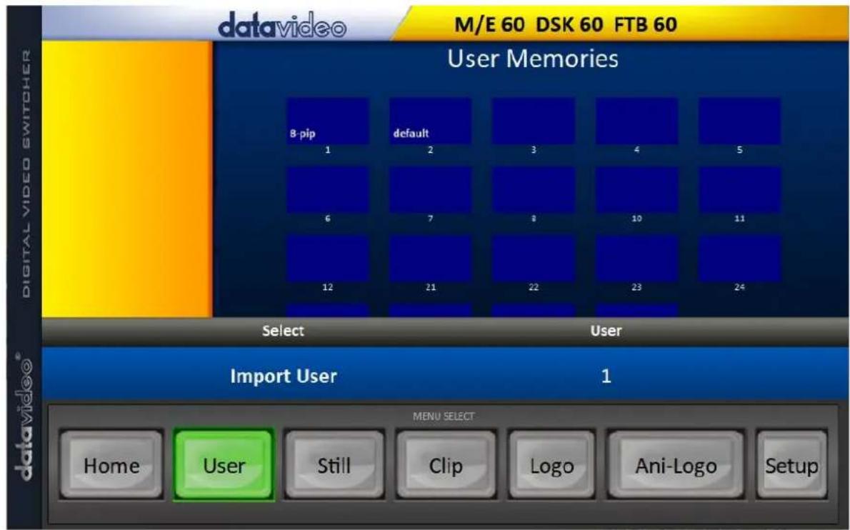
Click the User button to view all the .mem files saved on the switcher.
To import .mem files from your PC, click "User" then enter a memory location. Click "Import User" to browse your hard drive and select the user memory file that you would like to import.
See section 4.9, User Mems, for more details.
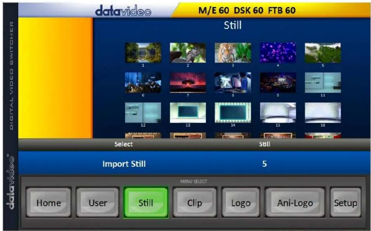
Still
Click the Still button to view all the still images saved on the switcher.
To import still image files from your PC, click "Still" then enter a memory location. Click "Import Still" to browse your hard drive and select the image file that you would like to import.
See section 4.9, Still, and section 5.3, Managing Still Pictures, for more details.
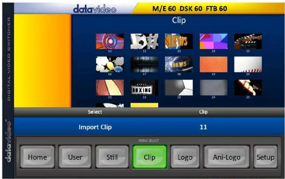
Clip
Click the Clip button to view all the clips saved on the switcher.
To import clip files from your PC, click "Clip" then enter a memory location. Click "Import Clip" to browse your hard drive and select the clip file that you would like to import.
See section 4.9, Clip, and section 5.4, Performing a Stinger Transition, for more details.
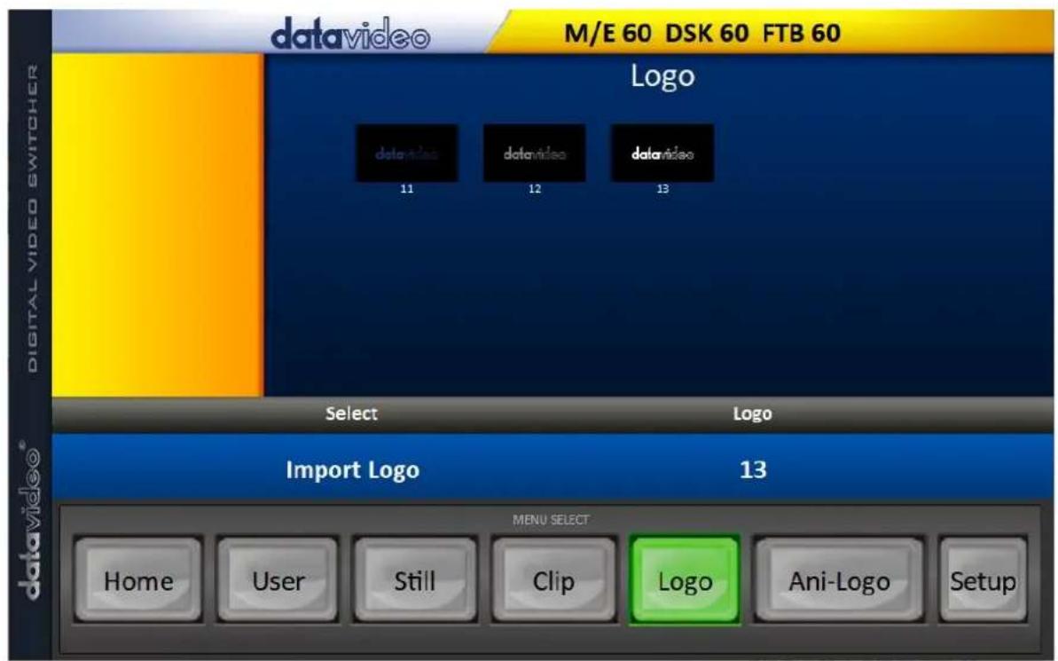
Logo
Click the Logo button to view all the still logo images saved on the switcher.
To import still logo image files from your PC, click "Logo" then enter a memory location. Click "Import Logo" to browse your hard drive and select the logo image file that you would like to import.
See section 4.9, Logo, and section 5.5, Enabling Still Logo, for more details.
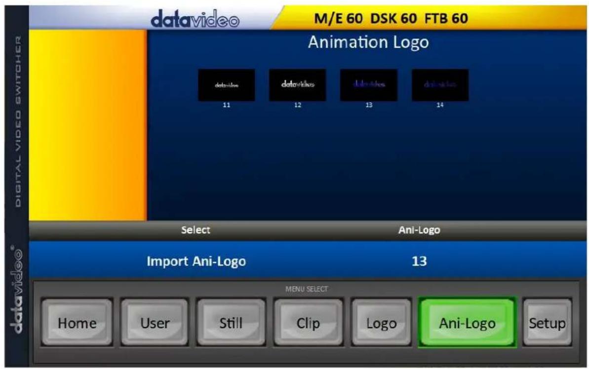
Ani-Logo
Click the Ani-Logo button to view all the animated logos saved on the switcher.
To import animated logo files from your PC, click "Ani-Logo" then enter a memory location. Click "Import Ani-Logo" to browse your hard drive and select the animated logo that you would like to import.
See section 4.9, Ani-Logo, and section 5.6, Enabling Logo Animation, for more details.
Setup
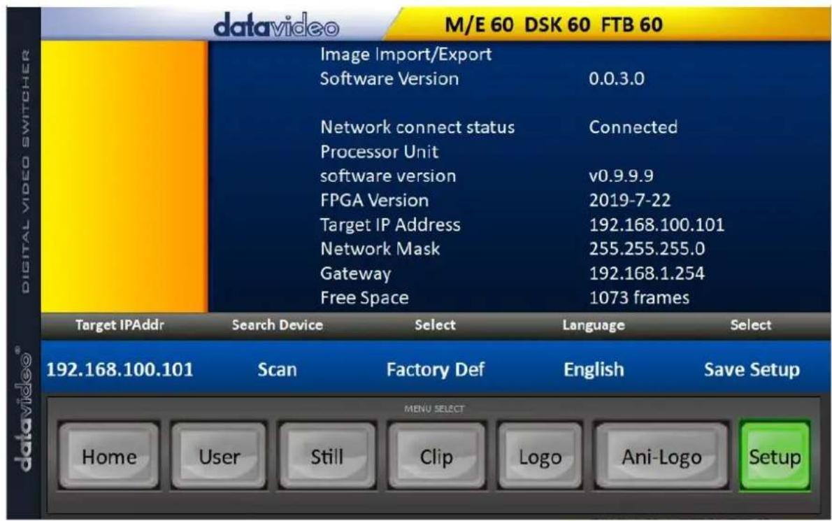
On the Setup page, you will be able to view the software version, network connect status, firmware version installed and the available space on the switcher.
The Setup page allows you to reset the software to its defaults, and change the interface language. The available languages are English, Traditional Chinese, and Simplified Chinese. Click Save Setup to apply the new settings.
The Target IP Address is the IP address of the switcher that you would like to connect. Enter the IP then click SCAN to connect to the switcher.
Chapter 4 OSD MENU
flowchart
graph TD
    A["MENU"] --> B["▲"]
    B --> C["ENTER"]
    C --> D["▼"]
    D --> E["▶"]
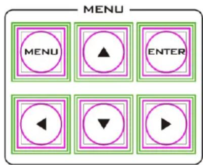
The switcher's OSD menu allows the user to perform several configurations of image effects, such as Picture-in-Picture, chroma key, subtitle overlay, still pictures and etc. The user can also configure the I/O by selecting different input and output options. In addition, in the setup menu, the user is allowed to set the menu color, size, position and language.
The OSD Menu can be opened in basic or advanced mode.
The basic mode is generally a condensed version of the advanced menu mode. The following sub-sections will show you the various options available in these two modes.
Overview
| Main Options | Sub-Options | Parameters | ||
| Start | Transition (Duration) | M/E | Mix Effect (0 - 9999 Default: 15) | |
| DSK | Downstream Key Effect (0 - 9999 Default: 15) | |||
| FTB | Fade-to-Black Effect (0 - 9999 Default: 60) | |||
| Type | DVE | |||
| Clip | ||||
| Wipe | ||||
| Mix | ||||
| Wipe Effects | Wipe | Wipe Effect Presets (1 - 32 Default: 1) | ||
| Soft | Border Softness (0 - 100% Default: 0%) | |||
| Width | Border Width (0 - 100% Default: 1%) | |||
| Border | Luma | Border Color Luma (0 - 100% Default: 100%) | ||
| Sat | Border Color Saturation (0 - 100% Default: 80%) | |||
| Hue | Border Color Hue (0 - 355 +/-5 Default: 0) | |||
| Position | X | Horizontal Position (0 - 1600% Default: 0%) | ||
| Y | Vertical Position (0 - 1600% Default: 0%) | |||
| Matte | Luma | Background Matte Luma (0 - 100% Default: 100%) | ||
| Sat | Background Matte Saturation (0 - 100% Default: 80%) | |||
| Hue | Background Matte Hue (0 - 355 +/-5) | |||
| Keyer | Keyer | DSK 2DSK 1Key 4Key 3Key 2Key 1Flex Key 1Flex Key 2 | Keyer Selection (Default: Key 4) | |
| Fine / Normal | Fine: High keying qualityNormal: Original keying quality | |||
| Keyer Ctrl | Full | Type of Keyer (Default: Linear) | ||
| ChromaLumaLinear | ||||
| Select one | P-in-PSelfSplit | Self: One input keyer (Default)Split: Dual input keyerP-in-P window enable | ||
| Lift | Parameter for dark/black areas of the overall foreground key image, ranging from -100% to +100% (Default: 0%). | |||
| Gain | Parameter for light/white areas of the overall foreground key image, ranging from 0 to 16.0 (Default: 1.0). | |||
| Opac | Parameter for transparency of the overall foreground key image, ranging from 0% to 100% (Default: 100%). | |||
| Invert | OFF: Luma key removes black background by defaultON: Luma key removes white background after INVERT is turned ON. | |||
| Key Source | BarsMatteFlex Src 2Flex Src 1Still 2Still 1Input 12Input 11Input 10Input 9Input 8Input 7Input 6Input 5Input 4Input 3Input 2Input 1Black | Key Source Selections (Default: Input 4) | ||
| Fill | Fill Source Selection from Bars / Matte / Flex Src 2 / Flex Src 1 / Still 2 / Still 1 / Input 12 / Input 11 / Input 10 / Input 9 / Input 8 / Input 7 / Input 6 / Input 5 / Input 4 / Input 3 / Input 2 / Input 1 / Black (Default: Black) | |||
| Mask | Left | Left sets the left edge of the keyer mask (Default: 0%). | ||
| Right | Right sets the right edge of the keyer mask (Default: 0%). | |||
| Top | Top sets the top edge of the keyer mask (Default: 0%). | |||
| Bottom | Bottom sets the bottom edge of the keyer mask (Default: 0%). | |||
| Chroma | Keyer | Flex Key 2Flex Key 1 | Keyer Selection (Default: Key 4) | |
| DSK 2DSK 1Key 4Key 3Key 2Key 1 | ||||
| Fine / Normal | Fine: High keying qualityNormal: Original keying quality | |||
| Key Source | BarsMatteFlex Src 2Flex Src 1Still 2Still 1Input 12Input 11Input 10Input 9Input 8Input 7Input 6Input 5Input 4Input 3Input 2Input 1Black | Key Source Selections (Default: Input 4) | ||
| Key Tie | ON/OFF | Still 1/2Input 1 – 12Flex Src 1/2Off | ||
| CK Setup | CK Auto | Calculation of the best Hue & Luma values for the current Keyer source | ||
| Hue | Parameter for color of the chroma key, ranging from 0 to 355 (Default: 110). | |||
| Luma | Parameter for luma of the chroma key, ranging from 0 to 100% (Default: 80%). | |||
| K Range | Setting the range of colors that match the background color to be keyed, ranging from 0 to 355 (Default: 160). | |||
| K Fgnd | Adjusts the performance of the chroma key in dark or black areas, ranging from 0% to 100% (Default: 10%). | |||
| K Bgnd | Adjusts the performance of the chroma key in light or white areas, ranging from K Fgnd value (min = 0) to 100% (Default: 20%). | |||
| Hi-Light | Boosts the foreground key in high luminance area, ranging from 0 to 100% (Default: 0%). | |||
| Lo-Light | Boosts the foreground key in low luminance area, ranging from 0 to 100% (Default: 0%). | |||
| Bg-Supp | Bg-Supp turns ON/OFF background suppress (Default: OFF). | |||
| Left | Trims the left edge of the key object (0 - 100% Default: 0%). | |||
| Right | Trims the right edge of the key object (0 - 100% Default: 0%). | |||
| Soft | Distinctiveness of key edge (0 - 100% Default: 0%) | |||
| Mask | Left | Left sets the left edge of the keyer mask (Default: 0%). | ||
| Right | Right sets the right edge of the keyer mask (Default: 0%). | |||
| Top | Top sets the top edge of the keyer mask (Default: 0%). | |||
| Bottom | Bottom sets the bottom edge of the keyer mask (Default: 0%). | |||
| P-in-P | P-in-P | Key 1Key 2Key 3Key 4Flex PinP 1Flex PinP 2Flex PinP 3Flex PinP 4 | Selection of PIP windows | |
| Fine | NormalFine | |||
| Position | X | Horizontal PIP Position (-100 - 100% Default: -20%) | ||
| Y | Vertical PIP Position (-56 - 56% Default: 10%) | |||
| Size | PIP Size (2 - 100% Default: 40%) | |||
| Border | Border OffNormalShaded3D BevelBevel ShadedDual BevelBevel FlatFlat Bevel3D GlassDual GlassGlass FlatFlat GlassCircleCircle ShadedRounded Rounded Shaded | Selection of border style (Default: Normal) | ||
| Luma | PIP Border Luma (0 - 100% Default: 100%) | |||
| Sat | PIP Border Color Saturation (0 - 100% Default: 80%) | |||
| Hue | PIP Border Color Hue (0 - 355 +/-5 Default: 0) | |||
| Width | PIP Border Width (0 - 100% Default: 2%) | |||
| Soft | Distinctiveness of Border Edge (0 - 100% Default: 0%) | |||
| Opac | Border transparency (0 - 100% Default: 100%) | |||
| Shade Matte | Luma | Shade Matte Luma (0 - 100% Default: 100%). | ||
| Sat | Shade Matte Saturation (0 - 100% Default: 80%). | |||
| Hue | Shade Matte Color (0 - 355 +/-5 Default: 60). | |||
| Shade Soft | This blurs or softens the Shade Matte area (0 - 100% Default: 2%). | |||
| Shade Pos | Sets position of the boundary line between Shade Matte and Border Matte (0 - 100% Default: 50%). | |||
| Direction | Direction of light source (0 - 355 +/-5 Default: 35). | |||
| Crop | Left | Left Edge of the Crop (0 - 100% Default: 0%). | ||
| Right | Right Edge of the Crop (0 - 100% Default: 0%). | |||
| Size | Size of the Crop (0 - 100% Default: 0%). | |||
| Top | Top Edge of the Crop (0 - 100% Default: 0%). | |||
| Bot | Bottom Edge of the Crop (0 - 100% Default: 0%). | |||
| Soft | Transparency and range of the crop edge (0 - 100% Default: 0%). | |||
| Flex Src | Flex Src | Flex Src 1 Flex Src 2 | ||
| Flex Src Bgnd | Bars Matte Flex Src Still 2 Still 1 Input 1-12 Black | Selection of Flex Screen sources and default is Black. Set ON to enable the respective P-in-P window, and OFF to disable. | ||
| P-in-P 1 Src | ||||
| P-in-P 2 Src | ||||
| P-in-P 3 Src | ||||
| P-in-P 4 Src | ||||
| Keyer 1 | Key Source: Bars Matte Still 2 Still 1 Input 1-12 Black | Fill Source: Bars Matte Still 2 Still 1 Input 1-12 Black | Enable: ON/OFF | |
| Keyer 2 | Key Source: Bars Matte Still 2 Still 1 Input 1-12 Black | Fill Source: Bars Matte Still 2 Still 1 Input 1-12 Black | Enable: ON/OFF | |
| Flex Preset | Preset 1 Preset 2 Preset 3 Preset 4 Preset 5 Preset 6 | Selection of Flex Screen layout. | ||
| Inputs | Input | Input 1-12Mode | Selection of an input to set the mode (Default: Input 1).Three input modes are Live, Freeze, and Still (Default is Live). | |
| Mode | Off | Mode disabled | ||
| TC-200 Md | Enables built-in TC-200Note: This option is only available at Input 9 to 12. | |||
| Zoom Md | Zoom: Enlarges or shrinks the selected input image horizontally and vertically at the same time.X: Enlarges or shrinks the selected input image horizontally.Y: Enlarges or shrinks the selected input image vertically. | |||
| Proc Amp | Black | Black level (0 - 100% Default: 0%) | ||
| White | White level (0 - 100% Default: 100%) | |||
| Chrom | Chroma level (0.0 - 16.0 Default: 1.0) | |||
| Audio | Gain | Audio volume of a selected video input (-60 - 24 dB Default: 0 dB). | ||
| Delay | Audio delay of a selected video input (0 - 340 ms Default: 0 ms). | |||
| Crosspoint | Input 1-12 Off | Assign the selected input source to an input button (Default is Input 1). | ||
| Audio XPT | Input 1-12 External Follow | Associate the audio component of a selected input source to an input button (Default is Follow). | ||
| Outputs | Output | SDI 1SDI 2SDI 3SDI 4SDI 5HDMI | Flex Src 2Flex Src 1Still 2Still 1Input 1 – 12CLN PVW (Clean PVW)CLN PGM (Clean PGM)PG + DSKPVWPGMMultiV2MultiV (Multi view)(SDI default: PGM / HDMI default: MultiV) | |
| Multiviewer | AutoNum | Auto number input labels (ON/OFF (Default)) | ||
| Label Inf | Input label is followed by information which describes the input as still, live or frozen image (ON/OFF (Default)) | |||
| Trns Lab | Turn the background of the label from a solid colour to transparent (ON/OFF (Default)) | |||
| MV1 | Multiview Layout ModesUser 1 – 8Preset 1 – 9Default: Preset 3 | |||
| MV2 | Multiview Layout ModesUser 1 – 8 | |||
| Preset 1 - 9Default: Preset 3 | ||||
| L: PGM / R: PVWL: PVW / R: PGM | Default: L: PVW / R: PGM | |||
| Tally Mode | Audio Mixer | Selection of tally light mode (Default: Normal) | ||
| Normal | ||||
| GPI Out | ON/OFF | GPI Enable/Disable (Default: OFF) | ||
| Mode | Level/Pulse (Default: Pulse) | |||
| Width | Pulse width (Default: 1) | |||
| Input 1-12 | GPI-out assignment (Default: Input 1) | |||
| Delay | 0-99 (Default: 0) | |||
| Audio | Audio | Mode | Turns ON/OFF embedded component at SDI-out and HDMI-out. | |
| Src | Selection of audio out source:PGM Audio (Default) / Follow / Input 1-12 | |||
| PGM Audio | Mode | Audio transition style: X Fade / V Fade(Default) | ||
| Gain | Audio volume of a selected video inputRange: -60 - 24 (dB) with default = 0 dB | |||
| Delay | Audio delay of a selected video inputRange: 0 - 340 ms with default = 0 ms | |||
| Analog Out | Src | Selection of audio out source:PGM Audio (Default) / Follow / Input 1-12 | ||
| Gain | Audio out volumeRange: -60 - 24 (dB) with default = 0 dB | |||
| Delay | Audio out delayRange: 0 - 340 ms with default = 0 ms | |||
| Files - Stills | Load Still | Load | Pressing this button loads the selected still picture source | |
| Still Num | 0-999 (Default = 1) | |||
| Destination | Still 1 (Default)Still 2Input 1 - 12 | |||
| Thumbnail Picture - 1 | Preview of the previous image | |||
| Thumbnail Picture | Preview of the image to be loaded | |||
| Thumbnail Picture + 1 | Preview of the next image | |||
| Save Still | Save | Pressing this button saves the selected still picture | ||
| Source | Still 1 (Default)Still 2Input 1 - 12 | |||
| Still Num | 0-999 (Default = 1) | |||
| Delete | Remove still from a memory location | |||
| Grab Still | Grab | Press this button to grab the current program view | ||
| Grab Destination | Still 1 (Default)Still 2 | |||
| Files - User Mems | Load Mem | Memory | Memory Selection from 1 to 999 (Default: 1) | |
| Load | Selection of this button loads the selected memory | |||
| Save Mem | Memory | Memory Selection from 1 to 999 (Default: 1) | ||
| Save | Selection of this button saves to the selected memory | |||
| Files - Clip | Load Clip | Load | Selection of this button loads the selected clip | |
| Clip Memory Location | Memory locations from 0 to 999 (Default = 0) | |||
| Clip Settings | Sets the clip's start and end frames and the transition frame.Start FrmEnd FrmMid Frm | |||
| Thumbnail Clip - 1 | Preview of the previous clip | |||
| Thumbnail Clip | Preview of the clip to be loaded | |||
| Thumbnail Clip + 1 | Preview of the next clip | |||
| Clear Clip | Clear the loaded clip | |||
| Delete Clip | Remove clip from a memory location | |||
| Files - Logo | Load Logo | Load | Loads the selected logo | |
| Logo Memory Location | Memory locations from 0 to 999 | |||
| Destination | Logo 1Logo 2 | |||
| Thumbnail Logo - 1 | Preview of the previous logo | |||
| Thumbnail Logo | Preview of the logo to be loaded | |||
| Thumbnail Logo + 1 | Preview of the next logo | |||
| Clear Logo | Clear the loaded logo | |||
| Delete Logo | Remove logo from a memory location | |||
| Logo 1 | X | X coordinate from -50 to +50 | ||
| Y | Y coordinate from -50 to +50 | |||
| Logo 2 | X | X coordinate from -50 to +50 | ||
| Y | Y coordinate from -50 to +50 | |||
| Files - Ani-Logo | Load Ani Logo | Load | Loads the selected animated logo | |
| Logo Memory Location | Memory locations from 0 to 999 | |||
| Destination | Logo 1Logo 2 | |||
| Thumbnail Logo - 1 | Preview of the previous animated logo | |||
| Thumbnail Logo | Preview of the animated logo to be loaded | |||
| Thumbnail Logo + 1 | Preview of the next animated logo | |||
| Clear Ani Logo | Clear the loaded animated logo | |||
| Delete Ani Logo | Remove animated logo from a memory location | |||
| Logo 1 | X | X coordinate from -50 to +50 | ||
| Y | Y coordinate from -50 to +50 | |||
| Logo 2 | X | X coordinate from -50 to +50 | ||
| Y | Y coordinate from -50 to +50 | |||
| Setup | Standard | 1080p/50/59.94/601080i/50/59.94/60720p/60/59.94/50 | Resolution Selection | |
| Level | Audio StandardsEBUSMPTEAUTO (Default) | |||
| Save Setup | Saves the selected resolution | |||
| Genlock | On/Off | |||
| H Phase | -2190 – 2190 ms | |||
| V Phase | -1124 – 1124 ms | |||
| OutConv | Off1080i50/59.94720p50/59.94 | Resolutions available for downconvert at SDI Out 5 | ||
| Menu Mode | Advanced | Full (Default) | ||
| Basic | Reduced | |||
| Brightness | 1 – 5 (Default: 5) | |||
| Menu Pref | Blue / Grey | Selection of menu color | ||
| Transp | Menu transparency level of 0/1/2 (Default: 1) | |||
| Position | This option sets the menu positionBottom (Default)RightLeftTopCentre | |||
| Auto Save | ON / OFF | Automatically saves the last settings before the machine is shut down; once turned ON auto save also occurs upon every Still Load. | ||
| Factory Def | Restore | Factory Default Reset loads the default configuration from memory point 0 for all configuration options except for the Setup. | ||
| Restr Names | Resets the Multiviewer labels to the default settings | |||
| Language | EnglishTraditional Chinese Simplified Chinese | |||
| Network | Addr Mode | DHCP(Default) / Static | ||
| IP Addr | ||||
| Network Mask | ||||
| Cancel / Save | ||||
| Network Def | Yes / No | |||
| Software | Upgrade | This starts the FW upgrade processSee the Firmware Upgrade section. | ||
4.1 Start
The Start menu allows the user to set the transition time, the transition type as well as various wipe effects. The menu options are shown below.
Advanced mode
| Start | Transition | M/E | 15 | DSK | 15 | FTB | 60 |
| Type | MIX | ||||||
| Wipe Effects | Wipe | 1 | Soft | 0% | Width | 1% | |
| Border | Luma | 100% | Sat | 80% | Hue | 0 | |
| Position | X | 0% | Y | 0% | |||
| Matte | Luma 100% | Sat 80% | Hue 0 |
Basic mode
| Start | Transition | M/E | 15 | DSK | 15 | FTB | 60 |
| Wipe Effects | Wipe | 1 | Soft | 0% | Width | 1% |
Transition
The Transition option allows the user to set the transition duration, in frames, for switching the PGM view when using the AUTO, DSK and FTB buttons.
For example, if the M/E is set to a value of 50, then the transition will take effect over a period of 50 frames or roughly 2 seconds. When the AUTO button is pressed, the transition will take the current M/E value defined by the user setting.
Type
The HS-3200 provides three major types of transition effect, which are DVE (3D), MIX, WIPE (2D) and Clip. Please note in addition to selecting the transition effect on the OSD menu, you can also press MIX button, WIPE/DVE button or CLIP button to enable the respective transition effects.
- If DVE is selected, select the corresponding 3D WIPE effect by pressing the DVE buttons on the control panel. These DVE buttons are:
DVE 1: Wipe from left to right
DVE 2: Wipe from top to bottom
DVE 3: Wipe from right to left
- For MIX effect, set the transition time in "Start → Transition → M/E."
- For WIPE effect, set the relevant WIPE settings in "Start WIPE Effects."
- For Clip, also known as the Stinger Effect, please first load the clip in "Files → Clip."
Wipe Effects
In “WIPE Effects,” the user is allowed to select the Wipe style and configure the wipe’s border softness and width.
- Wipe – Selection of a WIPE effect from a set of 32 WIPE transition effects.
- Soft – A low value results in a solid edge and a high value gives a soft diffused edge.
- Width – A low value results in a thin edge and a high value gives a wide edge.
WIPE Border
In this sub-option, the user will be allowed to fine-tune the border color by adjusting the Luma, Saturation and Hue values.
Note: Enable the WIPE border by setting the border width (Width) to a value greater than 0. The WIPE border is disabled when the border width is set to 0.
Position
Position allows the user to adjust the center position of certain wipes (e.g Circle & Elipse). X represents the horizontal position and Y is the vertical position.
Horizontal Position (X)
Positive value moves the wipe center to the right.
Negative value moves the wipe center to the left.
Zero value positions the wipe center at the screen center
Vertical Position (Y)
Positive value moves the wipe center up.
Negative value moves the wipe center down.
Zero value positions the wipe center at the screen center.
Matte
The user can open the Matte view by pressing the BLK/MATTE button of the Program and Preset button rows. The color of the Matte is configurable in this sub-option by adjusting Luma, Saturation and Hue.
For Hue value, Red is 0, Green is approximately 120 and Blue is approximately 240. For secondary colors, Yellow is approximately 60, Cyan is approximately 180 and Violet is approximately 300.
The Sat or Saturation value refers to the intensity of the color selected in Hue. As the saturation increases, the color appears to be more pure. As the saturation decreases, the color appears to be more washed-out or pale.
The Luma value relates to how bright or dark the selected color or hue is. The higher the Luma value, the brighter the color selected in Hue.
4.2 Keyer
Keyer of the HS-3200 provides the user with the capability of image keying. In this option menu, the user will be able to configure the eight keyers available on the HS-3200.
Advanced mode
| Keyer | Keyer | Key 4 | Normal | ||||
| Keyer Ctrl | Chroma | Self | Opac | 100% | |||
| Lift | 0% | Gain | 1.0 | Invert | Off | ||
| Key Source | Input 4 | Fill | Black | ||||
| Mask | Left | 0% | Right | 0% | |||
| Top | 0% | Bot | 0% | ||||
Keyer
The 8 keyer options are Key 1, Key 2, Key 3, Key 4, DSK 1, DSK 2, Flex Key 1 and Flex Key 2.
Key 1 – 4 are usually configured for luma and chroma keyers so select Self since only one source is enabled for such keyers.
The DSK keyer options are Linear and Luma. After the DSK keyer option is chosen, select Self if only one source is enabled for DSK keyer, which is the Key source. Select Split if two sources are enabled for the DSK keyer, which are Fill and Key sources. An example of a Linear DSK self setup could be using an HDMI input from a Windows laptop running Datavideo's CG-250 Character Generator software; see Character Generator for more information.
Once configured, the keyers can be activated by pressing the corresponding keyer buttons on the switcher's control panel except Flex Key 1 and Flex Key 2 which are enabled in the Flex Src sub menu. Please note that the Flex Keys, once configured and enabled, are displayed along with the Flex Screen. See Flex Src → Keyer for instructions on setting Flex Keys.
Select Fine if you require high keying quality and Normal for original keying quality.
Keyer Control
There are three keying modes available: Linear, Luma, and Chroma.
Please note that if you select Full, the keying effect will be disabled, keeping the original source image. For example, if you select Full → PIP, the keying effect will not be applied to the PIP image source.
Linear keying mode is usually chosen for sharp images as it is usually used in professional graphic design. For non-sharp images, please select Luma keying for basic text images. Chroma keying mode allows you to remove the green or blue backdrop from the image and is usually used in overlapping talent on a background image.
After the keying mode is chosen, select Self if only one source is required for the keyer, which is Key source. Select Split if two sources are required for the keyer, which are Key and Fill sources. You can also select P-in-P to apply the keying effect to the PIP window.
If Luma keying is selected, the key image is configured by adjusting lift, gain and opacity parameters.
Lift adjusts the dark/black areas of the key image. Reducing the value of Lift will make dark areas of the key image more transparent. The background image will be showing only through the transparent areas.
Gain adjusts the light/white areas of the key image. Increasing the value of Gain will make light areas of the key image more solid. The background image will be showing only through the transparent areas.
Opac adjusts the transparency of the overall foreground key image. Increasing the value of Opacity will make the overall key image less transparent.
Please note:
If Chroma is selected, adjust the Chroma Keyer parameters in the Chroma sub menu.
If P-in-P is selected, adjust its parameters in the P-in-P sub menu.
For example, if the user selects Key 1 → Chroma → P-in-P, you will then be able to apply the chroma key effect to the P-in-P window by configuring the respective chroma keyer parameters in the Chroma sub menu.
In the example below, after Keyer 1 is configured, by pressing the Key 1 PGM or PVW button on the switcher's control panel, the user will thus be able to enable the P-in-P window on the respective display monitor with the chroma key effect applied.
| Keyer | Keyer | Key 1 | Normal | |
| Keyer Ctrl | Chroma | Self | Opac 100% | |
| Lift 0% | Gain 1.0 | Invert Off | ||
| Key Source | Input 1 | Fill Black | ||
| Mask | Left 0% | Right 0% | ||
| Top 0% | Bot 0% |
Key Source
This option allows the user to assign the key source; various options are listed below:
- Bars: Color bars
• Flex Src 1/2: Selected Flex source (Flex Src option menu)
• Still 1/2: Still picture loaded to Still 1/2 buttons
• Input 12: Image source loaded to input button 12 - Input 11: Image source loaded to input button 11
- Input 10: Image source loaded to input button 10
• Input 9: Image source loaded to input button 9
• Input 8: Image source loaded to input button 8
• Input 7: Image source loaded to input button 7
• Input 6: Image source loaded to input button 6 - Input 5: Image source loaded to input button 5
- Input 4: Image source loaded to input button 4
• Input 3: Image source loaded to input button 3
• Input 2: Image source loaded to input button 2 - Input 1: Image source loaded to input button 1
- Black: Black Screen
- Matte: A configurable color screen and the Matte value can be set in Matte option of the Start menu
Fill Source
This sub-option allows the user to assign the fill source; various options are listed below:
- Bars: Color bars
- Matte: A configurable color screen and the Matte value can be set in Matte option of the Start menu
• Flex Src 1/2: Selected Flex source (Flex Src option menu)
• Still 1/2: Still picture loaded to Still 1/2 buttons
- Input 12: Image source loaded to input button 12
- Input 11: Image source loaded to input button 11
- Input 10: Image source loaded to input button 10
- Input 9: Image source loaded to input button 9
- Input 8: Image source loaded to input button 8
- Input 7: Image source loaded to input button 7
- Input 6: Image source loaded to input button 6
- Input 5: Image source loaded to input button 5
• Input 4: Image source loaded to input button 4
• Input 3: Image source loaded to input button 3
- Input 2: Image source loaded to input button 2
- Input 1: Image source loaded to input button 1
- Black: Black Screen
Invert
Configure the luma key color
OFF: Luma key removes black background by default.
ON: Luma key removes white background after INVERT is turned ON.
Mask
The Mask feature basically shrinks the source image by removing borders of the final image. In this option, the user is allowed to configure the Mask in chroma, luma or linear mode by adjusting Left, Right, Top and Bottom parameters.
- Left – Left sets the left edge of the keyer mask.
- Right – Right sets the right edge of the keyer mask.
- Top – Top sets the top edge of the keyer mask.
- Bottom – Bottom sets the bottom edge of the keyer mask.
4.3 Chroma
The Chroma Keyer removes the green background of the key image. If Chroma is selected in Keyer, this option menu allows you to configure the corresponding parameters.
Advanced mode options
| Chroma | Keyer | Key 4 | Normal | ||||
| Key Source | Input 4 | ||||||
| Key Tie | On | Input 6 | |||||
| CK Setup | CK Auto | Hue | 110 | Luma | 80% | ||
| K Range | 160 | K Fgnd | 10% | K Bgnd | 20% | ||
| Hi-Light | 0% | Lo-Light | 0% | Bg-Supp | OFF | ||
| Left | 0% | Right | 0% | Soft | 0% | ||
| Mask | Left | 0% | Right | 0% | |||
| Top | 0% | Bot | 0% | ||||
Keyer
First of all, select the Keyer (Key 1, Key 2, Key 3, Key 4, DSK 1, DSK 2, Flex Key 1 or Flex Key 2) that you would like to apply the chroma key effect to and then select one Key Source from all available Key Sources listed below.
Select Fine if you require high keying quality and Normal for original keying quality.
Key Source
This sub-option allows the user to assign a key source to the keyer selected; various options are listed below:
- Bars: Color bars
• Flex Src 1/2: Selected Flex source (Flex Src option menu)
• Still 1/2: Still picture loaded to Still 1/2 buttons - Input 12: Image source loaded to input button 12
- Input 11: Image source loaded to input button 11
- Input 10: Image source loaded to input button 10
- Input 9: Image source loaded to input button 9
- Input 8: Image source loaded to input button 8
- Input 7: Image source loaded to input button 7
- Input 6: Image source loaded to input button 6
- Input 5: Image source loaded to input button 5
- Input 4: Image source loaded to input button 4
• Input 3: Image source loaded to input button 3
• Input 2: Image source loaded to input button 2
• Input 1: Image source loaded to input button 1 - Black: Black Screen
- Matte: A configurable color screen and the Matte value can be set in Matte option of the Start menu
Key Tie
Key tie is a feature that allows you to overlap a foreground image on a background image. The key tie image can then be opened by pressing the input button to which the background image is assigned. Note that the keyer button will be disabled if key tie is enabled for the corresponding keyer. Outlined below are steps to set key tie with the chroma keyer.
- First, in the Keyer menu, select the keyer and set it to Chroma. We used Key 1 in this example.
| Keyer | Keyer | Key 1 | Normal | ||||
| Keyer Ctrl | Chroma | Self | |||||
| Lift 0% | Gain 1.0 | Opac 100% | |||||
| Key Source | Input 3 | Fill | Input 12 | Invert | Off | ||
| Mask | Left 0% | Right 0% | |||||
| Top 0% | Bot 0% | ||||||
- Open the Chroma menu and select Key 1. Assign a foreground image to the Key Source (the foreground image is usually a person or an object against a green backdrop). In this case, it's Input 3.
| Chroma | Keyer | Key 1 | Normal | ||||
| Key Source | Input 3 | ||||||
| Key Tie | Off | Off | |||||
| CK Setup | CK Auto | Hue | 110 | Luma | 80% | ||
| K Range | 160 | K Fgnd | 10% | K Bgnd | 20% | ||
| Hi-Light | 0% | Lo-Light | 0% | Bg-Supp | OFF | ||
| Left | 0% | Right | 0% | Soft | 0% | ||
| Mask | Left | 0% | Right | 0% | |||
| Top | 0% | Bot | 0% | ||||
- Enable Key Tie and on the right, select a background image.
| Chroma | Keyer | Key 1 | Normal | ||||
| Key Source | Input 3 | ||||||
| Key Tie | On | Input 6 | |||||
| CK Setup | CK Auto | Hue | 110 | Luma | 80% | ||
| K Range | 160 | K Fgnd | 10% | K Bgnd | 20% | ||
| Hi-Light | 0% | Lo-Light | 0% | Bg-Supp | OFF | ||
| Left | 0% | Right | 0% | Soft | 0% | ||
| Mask | Left | 0% | Right | 0% | |||
| Top | 0% | Bot | 0% | ||||
- After key tie is configured, to open the key tie image, simply press the input button of the background image selected at Step 3. In this example, input 6 is selected as the background so press button 6 on either the Preset or Program row to open the key tie image on the respective views.
Below are available sources of the background image:
- Still 1/2
- Input 1–12
- Off
Note: You will not be able to use the keyer button once key tie is enabled. Use the input button that is assigned to the background image to open the key tie image.
CK Setup
In this sub-option, the user will be able to find all the parameters needed to perform chromakeying of the green or blue backdrop.
CK Auto: This function automatically calculates the best Hue & Luma values for the current Keyer source. After applying the CK Auto effect, the result can be fine-tuned by adjusting the Luma and Hue values.
Hue: This parameter adjusts the color of the chroma key. A typical green screen value will be around 120. Blue screen value will be around 240.
Luma: This parameter adjusts the luma value of the chroma key
K Range (Key Range): Key Acceptance sets the range of hues or colors (0 – 360 degrees) that closely match the background color to be keyed. The user can start with a value of 120 degrees and this value can be fine-tuned up or down depending on the setup of the green or blue screen studio.
K Fgnd (Key Foreground): Key Foreground adjusts the performance of the chroma key in light or white areas. Apply more Key Foreground if the light areas are becoming too transparent.
K Bgnd (Key Background): Key Background adjusts the performance of the chroma key in dark or black areas. Apply more Key Background if the dark areas are becoming too transparent.
Hi-Light: Hi-light boosts the foreground key in high luminance area.
Lo-Light: Lo-light boosts the foreground key in low luminance area.
Bg-Supp: Background Suppress removes the Luma (Brightness) of the background from the final image. Bg-Supp turns ON/OFF background suppression.
Left: Trims the left edge of the key object.
Right: Trims the right edge of the key object.
Soft: Determines the distinctiveness of key edge
Mask
The Mask feature basically shrinks the camera image by removing the borders from the final image. This feature allows the user to configure the Mask in chroma, luma or linear mode.
- Left – Left sets the left edge of the keyer mask.
- Right – Right sets the right edge of the keyer mask.
- Top – Top sets the top edge of the keyer mask.
- Bottom – Bottom sets the bottom edge of the keyer mask.
4.4 P-In-P
The P-in-P option allows the user to adjust all related P-in-P parameters. Use this option to configure your PIP window if P-in-P is selected in the Keyer Ctrl sub-option of the Keyer option.
Note: The P-in-P image source can only be selected in Key Source option of the Keyer Sub Menu.
Advanced mode options
| P-in-P | Keyer | Key 1 | Fine | Normal | ||
| Position | X -20% | Y | 10% | Size | 40% | |
| Border | Normal | |||||
| Luma 100% | Sat | 80% | Hue | 0 | ||
| Width 2% | Soft | 0% | Opac | 100% | ||
| Shade Matte | Luma 100% | Sat | 80% | Hue | 60 | |
| Shade Soft 2% | Shade Pos | 50 | Direction | 35 | ||
| Crop | Left 0% | Right | 0% | Size | 0% | |
| Top 0% | Bot | 0% | Soft | 0% | ||
Keyer
In this sub-option, the user will be allowed to select and configure the PIP window from the list below. Please note that Keyers 1-4 are active for PIP configuration only if P-in-P is selected in the Keyer sub-menu for the respective keyer.
• Key 1
• Key 2
• Key 3
• Key 4
- Flex PinP 1
- Flex PinP 2
- Flex PinP 3
- Flex PinP 4
Position
The user can adjust the P-in-P window position by adjusting values of X, Y and SIZE, where X is the horizontal position, Y is the vertical position and Size is the PIP screen size.
X-Value Positive value: position the P-in-P window to the right. Negative value: position the P-in-P window to the left. Zero value: Position the P-in-P window at the center.
Y-Value Positive value: move the P-in-P window up. Negative value: move the P-in-P window down. Zero value: Position the P-in-P window at the center.
Size Ranges from 0 to 100 with 1% being the smallest and 100 being the largest. So 50% would represent a P-in-P window which is half the size of the background image. 100% would see the PIP image totally cover the background image unless offset to one side.
Fine
Once enabled, you will then be able to fine tune the position of the P-in-P window by adjusting X and Y vales as well as the Size. This feature allows you to move the P-in-P window more precisely to the desired location and adjust its size.
Border
The user is also allowed to add borders to the PIP window and the HS-3200 offers various border styles listed as follows:
- Border Off
- Normal
- Shaded*
- 3D Bevel**
- Bevel Shaded*
- Dual Bevel**
- Bevel Flat**
- Flat Bevel**
- 3D Glass**
- Dual Glass**
- Glass Flat**
- Flat Glass**
- Circle**
- Circle Shaded*
- Rounded**
- Rounded Shaded*
*See Shade Matte/Hue for dual color border setting.
**See Shade Matte/Direction for border shadow setting.
To turn the Border off, simply select the option "Border OFF."
In addition to assigning a style to the border, the user is also allowed to set border color by adjusting Luma, Saturation and Hue values. Luma and Saturation range from 0 to 100%. Hue value ranges from 0 to 355. The borders can also be widened or narrowed by adjusting Width. Please note that a width of zero (0) will turn the PIP border off.
Opac adjusts the transparency of the border, ranging from 0% to 100%
Softness defines the distinctiveness of the border edge. A low value results in a solid border edge and a high value gives a soft diffused border.
Shade Matte (Dual Color Border)
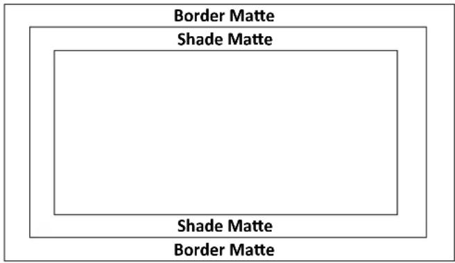
In order for the Shade effect to work, Shaded Border (Dual Color) must be selected first as the Border – see the previous section Border. Please note that Shade Matte determines the inner border and the boundary between the normal border matte and the shade matte can be determined by adjusting the Shade Position parameter.
Luma, Sat and Hue
The color of the Shade Matte can also be controlled by adjusting the Hue, Sat and Luma values.
For Hue value, Red is 0, Green is approximately 120 and Blue is approximately 240. For secondary colors, Yellow is approximately 60, Cyan is approximately 180 and Violet is approximately 300.
The Sat or Saturation value refers to the intensity of the color selected in Hue. As the saturation increases, the color appears to be more pure. As the saturation decreases, the color appears to be more washed-out or pale.
The Luma value relates to how bright or dark the selected color or hue is. The higher the Luma value, the brighter the color selected in Hue.
Shade Softness, Shade Position and Direction
The Shade Matte can be further configured by adjusting its softness (Shade Soft) and width (Shade Pos).
Shade Soft
This blurs or softens the Shade Matte area.
Shade Position
The position of the boundary line between Shade Matte and Border Matte is controlled by the Shade Pos value.
Increasing this value moves the boundary line such that the Shade Matte occupies less of the width of the border. Decreasing this value moves the boundary line such that the Shade Matte occupies more of the overall border width. When this value is 0, the Shade Matte occupies all of the border width.
Note: You will see dual colors only if options “Shaded” and “Bevel Shaded” are selected.
Direction
Direction sets the direction of the light source with the value of parameter ranging from 0 to 355. The default is 35, which indicates a direction of North East. You will see the border's color shadow changes as the Direction value is changed. The directions that specific parameter values correspond to are listed as follows:
- 0: North
- 90: East
• 180: South
• 270: West
Crop
The PIP image crop can be adjusted by modifying the following parameters:
- Left – Adjusts the position of the left edge of the PIP image.
- Right – Adjusts the position of the right edge of the PIP image.
- Size – Adjusts the PIP image crop size.
- Top – Adjusts the position of the top edge of the PIP image.
- Bot – Adjusts the position of the bottom edge of the PIP image.
- Soft – Adjusts the crop edge transparency.
Note: You will sometimes see black thin lines on your PIP image after setting the PIP border to Normal with a border width of zero. This is caused by using an image that differs from its original size. To remove these lines, turn the border off or use the crop function to shrink the image until the lines disappear.
4.5 Flex Src
The Flex™ output allows the user to show a variety of sources at the same time. These image sources are fed as one combined image to the Program and Preset outputs.
The Flex™ output consists of one background image and four smaller source images overlapped on the background image in four separate individual PIP windows.
The HS-3200 offers the user two Flex™ outputs, which can be selected in "Flex Src" as shown in the Flex Src sub menu below. After selecting the Flex output, you can then start setting the source of input for each FLEX window as detailed in the next section.
| Flex Src | Flex Src Flex Src Bgnd | Flex Src 1 | |||
| Black | |||||
| P-in-P 1 Src | Black | Enable | On | ||
| P-in-P 2 Src | Black | Enable | On | ||
| P-in-P 3 Src | Black | Enable | On | ||
| P-in-P 4 Src | Black | Enable | On | ||
| Keyer 1 | Input 1 | Input 2 | Enable | On | |
| Flex Preset | Preset 1 | Preset 2 | Preset 3 | ||
| Preset 4 | Preset 5 | Preset 6 | |||
Flex Screen
To set the source of input for the respective FLEX windows, open the OSD menu and select FLEX Src. On the sub-menu that opens, you will be able to see the following options allowing you to select the image sources to be displayed in the FLEX windows.
- Flex Src Bgnd: The background image is the image on which the FLEX windows are stacked.
- P-in-P 1 Src selects the image displayed in FLEX window 1.
- P-in-P 2 Src selects the image displayed in FLEX window 2.
- P-in-P 3 Src selects the image displayed in FLEX window 3.
• P-in-P 4 Src selects the image displayed in FLEX window 4.
The available sources of inputs are listed as follows:
- Black: Black Screen
- Input 1: Image source loaded to input button 1
- Input 2: Image source loaded to input button 2
- Input 3: Image source loaded to input button 3
- Input 4: Image source loaded to input button 4
- Input 5: Image source loaded to input button 5
• Input 6: Image source loaded to input button 6
• Input 7: Image source loaded to input button 7 - Input 8: Image source loaded to input button 8
• Input 9: Image source loaded to input button 9 - Input 10: Image source loaded to input button 10
- Input 11: Image source loaded to input button 11
- Input 12: Image source loaded to input button 12
• Still 1: Still picture loaded to Still 1 button
• Still 2: Still picture loaded to Still 2 button - Bars: Color Bars
- Matte: A configurable color screen and the Matte value can be set in Matte option of the Start menu
Keyer
The Flex Keyer can be set to Chroma, Luma or Downstream keyer. In the Keyer sub menu, first select the Flex Key with respect to the Flex Source selected in "Flex Src". Then if a Chroma or Luma Self key setup is selected, only one source is enabled for the keyer, which is key source. If you've selected a DSK Split setup, then two sources should be enabled for the DSK keyer, which are Key and Fill sources.
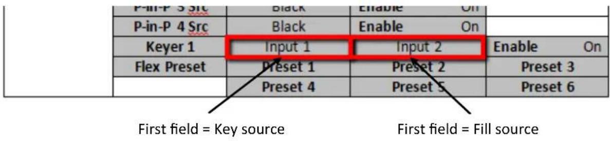
In Keyer of the Flex Src sub menu, the first field corresponds to the key source and the second field selects the fill source.
If you've selected Chroma key setup, the keyer can be configured in Chroma sub menu.
If you've selected Luma key setup, adjust Lift, Gain and Opac in Keyer sub menu.
For a Linear DSK self setup, a good example could be using an HDMI input from a Windows laptop that is running Datavideo's CG-250 Character Generator Software; see Character Generator for more information.
Key source and Fill source will be required for a DSK split setup. The steps outlined below will guide you through the configuration process of such.
System Hardware Setup
- Connect the laptop to the PC IN HDMI port of the TC-200 Title Creator using an HDMI cable.
- Open CG-250 on the laptop and create a CG image that can then be sent to the HS-3200 via TC-200.
- At the rear of the HS-3200, the two SDI output ports of the TC-200, Key Source and Fill Source, are respectively connected to the HS-3200's SDI 1 and SDI 2 inputs.
- Switch ON the HS-3200's power button and after the boot up is complete, the Multiview should be displayed on the connected monitor.
Menu Settings
- On the Multiview, Input 1 window displays the Key Source, Input 2 window displays the Fill Source.
- Follow the menu path Keyer → Keyer and select either Flex Key 1 or 2 depending on the Flex screen selected in Flex Src.
- Follow the menu path Keyer → Keyer Ctrl and set the Flex Key to a linear or luma DSK split keyer.
- Follow the menu path Flex Src → Keyer1 (Keyer2) and set CG Overlay inputs by selecting Input 1 (Key) in the first field and Input 2 (Fill) in the second field.
| Flex Src | Flex Src | Flex Src 1 | ||
| Flex Src Bgnd | Black | |||
| P-in-P 1 Src | Black | Enable On | ||
| P-in-P 2 Src | Black | Enable On | ||
| P-in-P 3 Src | Black | Enable On | ||
| P-in-P 4 Src | Black | Enable On | ||
| Keyer 1 | Input 1 | Input 2 | Enable On | |
| Flex Preset | Preset 1 | Preset 2 | Preset 3 | |
| Preset 4 | Preset 5 | Preset 6 |
After the keyer is configured, enable the keyer and on the switcher's control panel, press and hold the SHIFT button then press the 3/FLEX button on either the Preset or Program row to view the Flex screen with CG enabled.
Flex Preset
The HS-3200 offers the user three FLEX Screen layouts. The respective default layouts are shown in the diagrams below.
Preset 1
| Flex Src – P-in-P 1 Src | Flex Src – P-in-P 2 Src |
| Flex Src – P-in-P 3 Src | Flex Src – P-in-P 4 Src |
Preset 2
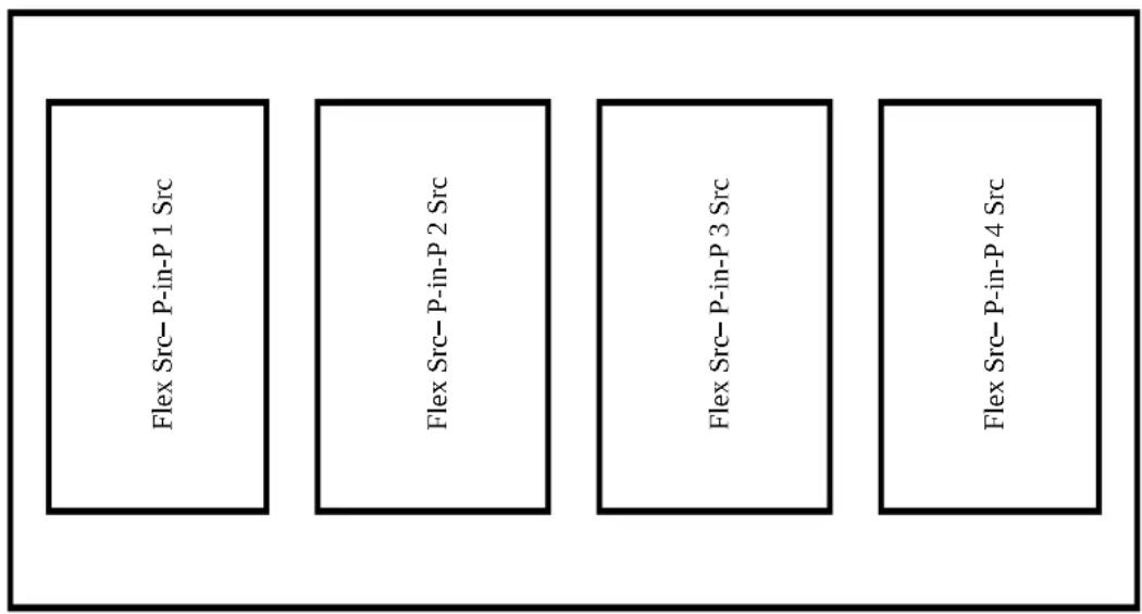
Preset 3
| Flex Src – P-in-P 3 Src | Flex Src – P-in-P 4 Src |
| Flex Src – P-in-P 2 Src | |
| Flex Src – P-in-P 1 Src |
Note: Presets 4 to 6 are reserved for future developments.
Please note that positions of these PIP windows on the FLEX screen can be changed by adjusting the x-y coordinates in the P-in-P option. In addition, the user is also allowed to adjust the size of the FLEX window, enable/disable the window's border, set the border color, and crop the window image.
After the FLEX source is properly configured, the user can activate Flex Src 1 on either the Program or Preset screen by pressing the SHIFT key followed by the 3/FLEX button (the button should illuminate blue) along the Program or Preset row. Press the 3/FLEX button (the button should illuminate orange) again while holding down the SHIFT key to activate Flex Src 2.
Alternatively, press the BLK/MATTE button which should turn blue, then press the 3/FLEX button to activate Flex Src 1 (3/FLEX button flashing blue) and again to activate Flex Src 2 (3/FLEX button flashing red).
Note that the Flex Src window has an allowable size of up to 1080p full screen. If exceeded, one of the Flex Src windows will not be able to display the image correctly.
4.6 Inputs
This feature allows the user to select the mode of the selected input and then configure the input color by adjusting its Black Level, White Clip and Chroma Gain parameters. In addition, the Crosspoint function allows the user to shuffle contents of Inputs 1-12 without changing physical connections at the back of the machine.
Advanced mode options
| Inputs | Input | Input 9 | Mode | Live | Mode | Zoom Md | |
| Zoom | 100% | X | 0% | Y | 0% | ||
| Proc Amp | Black | 0% | White | 100% | Chrom | 1.0 | |
| Audio | Gain 0 dB | Delay 0 ms | ||
| Crosspoint | Input 9 | |||
| Audio XPT | Off |
Input
In this option, you will be allowed to set the mode of display in the respective Input windows of the Multiview display. First select the input that you would like to configure and then for each selected input, set the mode of input by selecting one of the modes from the first mode option:
- Still – Displays the still picture loaded into Inputs 1-12 in the respective input window.
- Freeze – Freezes the current video played in the Input window.
• Live – Live view or video display in the Input window.
Mode of Operation
The second mode option allows you to select the mode of operation for the selected input.
Zoom Mode: This mode allows you to enlarge or shrink the selected input image. Select Zoom if you want to simultaneously adjust your image size horizontally and vertically. To adjust the image size horizontally only, simply change the X value and to adjust the image size vertically only, simply change the Y value.
TC-200 Mode: The TC-200 is a character generator built into the switcher to allow keying of CG text or graphics over the live video. Built-in TC-200s are available on Inputs 9-12 only.
Please note that the following hardware restrictions apply when using this feature.
- The built-in title overlay system (TC-200) works better with ATI and Intel VGA graphics cards.
- Compatibility issue such as color difference may occur when used with NVIDIA graphics cards.
First ensure that your input image or video resolution matches the switcher's resolution set in OSD menu → Setup → Standard, then follow the steps below to set up your CG text or graphics after TC-200 mode is enabled on the selected input (Inputs 9-12).
- Connect the laptop to one of the HDMI ports of the HS-3200 switcher using an HDMI cable. In this example, we will be using HDMI port 9 for illustration purpose.
- Open CG-250 on the laptop and create a CG image that can then be sent to the HS-3200 via the built-in TC-200.
- Switch ON the HS-3200's power button and after the boot up is complete, the Multiview should be displayed on the connected monitor.
- On the Multiview, Input 9 window should display the CG image.
-
Press the "MENU" button on the HS-3200's control panel to open the OSD menu on the Multiview display and then select the "Inputs" sub menu.
-
Select "Input 9" from the Input option and enable TC-200 mode by turning on TC-200 Md.
| Inputs | Input | Input 9 | Mode | Still | Mode | TC-200 Md | |
| Proc Amp | Black | 0% | White | 100% | Chrom | 1.0 | |
| Audio | Gain | 0 dB | Delay | 0 ms | |||
| Crosspoint | Input 9 | ||||||
| Audio XPT | Off | ||||||
-
Move to the "Keyer" sub menu.
-
Select "DSK 1 or 2" from the Keyer option and set Key and Fill Sources to Input 9.
| Keyer | Keyer | DSK1 | Normal | ||||
| Keyer Ctrl | Linear | Split | Opac | 100% | |||
| Lift | 0% | Gain | 1.0 | Invert | Off | ||
| Key Source | Input 9 | Fill | Input 9 | ||||
| Mask | Left | 0% | Right | 0% | |||
| Top | 0% | Bot | 0% | ||||
- Locate DSK buttons on the switcher's control panel then depending on the settings selected at Step 8, press DSK 1 or 2 button to open your CG graphics on either of the preview and program windows or both.
Proc Amp
Proc Amp allows the user to configure the input color by adjusting its Black Level (0 – 100%), White Clip (0 – 100%) and Chroma Gain (0 – 16) parameters.
Audio
Gain (0 - 24 dB): adjustment of the input audio volume for a particular selected video input.
Delay (0 – 340 ms): sets the delay of the audio component of a particular selected video input.
Crosspoint
The crosspoint function allows the user to shuffle the contents of Inputs 1-12 without changing the physical connections at the back of the machine. For example, the user is allowed to assign the input 2 video source to input 1, after which the input 2 video will be displayed on the input 1 window. Select OFF if you would like to disable the input port.
- Input 1-12
- OFF
Audio XPT
The Audio XPT feature allows the user to associate the audio component of any input source to any of the input buttons (1 – 12), thus cross assigning audio input channels to program/preset row buttons. Available options are listed as follows:
- Input 1-12
- External
- Follow
"External" selects audio source from AUDIO IN ports.
Select "Follow" to set the audio to Audio-Follow-Video mode in which the PGM audio is played via AUDIO OUT port. Please note that there will be no audio delay.
4.7 Outputs
This option allows the user to configure various output settings such as video output, Tally mode and GPI connection.
Advanced mode
| Outputs | Output | Sdi 1 | Input 1 | Sdi 2 | Input 2 | Sdi 3 | Input 3 |
| Sdi 4 | Input 4 | Sdi 5 | Input 5 | ||||
| HDMI | Pgm | ||||||
| Multiviewer | AutoNum | Off | Label Inf | Off | Trns Lab | Off | |
| MV1 | Preset 3 | MV2 | Preset 1 | L: PVW | R: PGM | ||
| Tally Mode | Normal | ||||||
| GPI Out | Off | Mode | Pulse | Width | 1 | ||
| Input 1 | Delay | 0 | |||||
Basic mode
| Outputs | Output | Sdi 1 | Input 1 | Sdi 2 | Input 2 | Sdi 3 | Input 3 |
| Sdi 4 | Input 4 | Sdi 5 | Input 5 | ||||
| HDMI | Pgm | ||||||
| Multiviewer | AutoNum | Off | Label Inf | Off | Trns Lab | Off | |
| MV1 | Preset 3 | MV2 | Preset 1 | L: PGM | R: PVW |
Outputs
In general, the HS-3200 offers 6 configurable output ports (SDI 1 - 5 / HDMI) and all 6 ports can be configured to output one of the following:
- Flex Src 1/2
- Still 2
- Still 1
- Input 1 – 12
• CLN PVW (Clean PVW)
• CLN PGM (Clean PGM)
- PG + DSK
• PVW
- PGM
- MultiV2 (Multi view 2)
- MultiV (Multi view)
Multiviewer
AutoNum: The Multiview windows can be automatically numbered, and this option turns ON/OFF automatic numbering.
Label Inf turns ON/OFF Label information. Input label indicates whether the input is still (stl), live (*), or a frozen image (frz).
Trns Lab turns ON/OFF the Label Transparency. Once enabled, the background of the label should turn from an opaque black to a transparent one.
MV1/2
The HS-3200 Multi-view monitoring is available in different multi-image layouts. These outputs can be used to monitor video and audio in a number of different configurations. For each setup, embedded audio level indication is also available on all inputs as well as the Preview and Program windows.
| Preset 1 | Preset 2 | ||||||
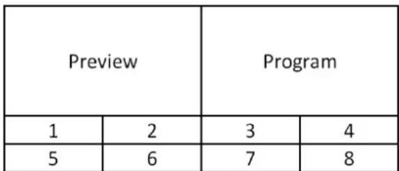 | 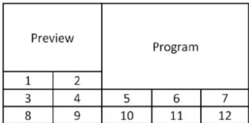 | ||||||
| Preset 3 | Preset 4 | ||||||
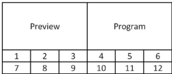 | 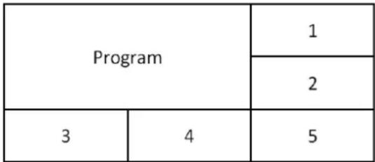 | ||||||
| Preset 5 | Preset 6 | ||||||
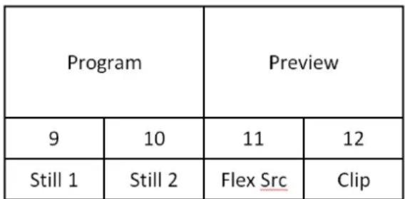 | 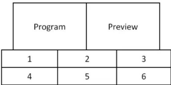 | ||||||
| Preset 7 | Preset 8 | ||||||
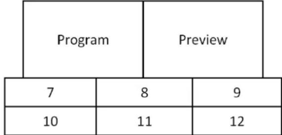 | |||||||
| 1 | 2 | 3 | 4 | ||||
| 5 | 6 | 7 | 8 | ||||
| 9 | 10 | 11 | 12 | ||||
| Preset 9 | |||||||
| Program | Preview | ||||||
| 1 | 2 | 3 | 4 | ||||
| 5 | 6 | 7 | 8 | ||||
| 9 | 10 | 11 | 12 | ||||
| 1 | 2 | 3 | 4 |
| 5 | 6 | 7 | 8 |
| 9 | 10 | 11 | 12 |
R/L
On the Multiview, by default, Preview window is positioned on the left and on the right is the Program window. This option allows you to switch their positions.
Tally Mode
Tally output port generally sends two tally signals to each channel. In Datavideo products, Red indicates On-Air, and Green indicates next video source. On the Multiview screen, the tally light is indicated by rectangular borders around the input sub windows.
The HS-3200 provides two tally modes:
Normal: If in normal mode, tally lights of all video sources enabled on PGM view will be turned ON (Red). These sources include PGM, PIP and Key sources. While transition is in progress, tally lights of all video sources enabled on PGM view do not change color. The tally light will only change color (Red → Green) after transition of PGM and PVW views is complete. However, for video sources on the Preview window, the tally lights will be enabled Green, and the color is changed to Red as soon as the transition is triggered.
Audio Mixer: If Audio Mixer mode is selected, tally lights of all video sources enabled on PGM view will be turned ON (Red). While transition is in progress, tally lights of all video sources enabled on PGM view do not change color. The tally light will only change color (Red → Green) after transition of PGM and PVW views is complete. However, for video sources on the Preview window, the tally lights will be enabled Green, and the color is changed to Red as soon as the transition is triggered.
GPI Out
GPI is designed to allow the user to trigger playback of an external playback device such as Datavideo's NVP-20 or HRS-30 unit. GPI OUT allows the user to configure your GPI connection.
First enable the GPI port and then set the GPI mode, which is either level or pulse. The pulse width can be configured in Width sub-option (1-9).
Once the GPI function is enabled, you can assign it to one of Inputs 1-12 which can later be used to trigger external devices and the delay can be set to a value between 0 and 99.
4.8 Audio
In the Audio menu, you will be able to start and shut off the embedded audio of SDI and HDMI videos.
| Audio | Audio | Mode | On | Src | Input 1 | |
| PGM Audio | Mode | V Fade | Gain | 0 dB | Delay 0 ms | |
| Analog Out | Src | Follow | Gain | 0 dB | Delay 0 ms |
Audio
External audio source can only enter the HS-3200 via the analog XLR input port found on the rear panel of the main unit. Ideally the user should use the HS-3200 with an audio mixer.
It is recommended to use AM-100 or AD-200 audio mixer designed and manufactured by Datavideo. All external audio sources can be connected to AM-100 or AD-200 before entering the HS-3200. The external audio can be embedded into SDI video out.
Mode (ON/OFF): Setting Mode ON allows the HS-3200 to embed external audio component into SDI video out. Changing the Mode option from ON to OFF will mute the embedded audio.
Audio Src: This sub-option allows the user to select the audio source.
If "External" is selected, the external audio, i.e. audio from AUDIO IN port, will be played.
If "Follow" is selected, the audio will enter Audio follow Video mode, i.e. playback of the audio of the output video.
To play the audio of a particular input video channel, select an input number from Input 1-12.
PGM Audio
While working in the Audio-F-Video mode, the audio sources will also change as the video sources are switched. We can choose how the audio changes sources, whether it be a clean cut (immediate switch) or some sort of transitioned change (cross fade or fade out & in). To do this we would need to set up with the following menu options.
• X Fade: PGM Audio / PVW Audio cross fade
• V Fade: Fade out PGM Audio then fade in PVW Audio
Gain (0 - 24 dB): adjustment of the PGM audio volume.
Delay (0 - 340 ms): sets the delay of the PGM audio volume.
Analog Out
You are also allowed to select a source of audio of your preference and output the selected audio via Audio OUT. Open the OSD menu and select Audio → Analog Out → Src where you may select a source of audio from the following list.
- PGM Audio
- Follow
- Input 1-12
If “Follow” is selected, the audio will enter Audio follow Video mode, i.e. playback of the PGM audio via Audio OUT without audio output delay. If “PGM Audio” is selected, the HS-3200 will only play the PGM audio via Audio OUT with audio output delay. You may also select to output one audio component of the 12 inputs via Audio OUT without audio output delay.
Gain (-60 - 24 dB): adjustment of the audio volume at the AUDIO OUT.
Delay (0 - 340 ms): sets the delay of the audio at the AUDIO OUT.
4.9 Files
In Files, you will be allowed to manipulate different files such as clips, still pictures, user memories and still and animated logos.
Still allows the user to load images from the memory, save images to the memory, and save the images captured. User allows you to load previously saved settings and save the currently configured settings. In Clip, you will be able to browse through the clip files and load the clips directly on the switcher. As for logo and ani logo menus, they allow you to load still and animated logos directly on the switcher.
All five file types will be discussed in the following sub-sections.
User Mems
In this option, the user is allowed to load previously saved settings and save the currently configured settings.
Advanced mode options
| Files | User | |||
| Load Mem | Memory 1 | Load | ||
| Save Mem | Memory 1 | Save |
Load Memory
Use the up/down arrow to scroll to the desired memory location and load the saved setting by selecting "Load".
Note: The user can also press one of the USER memory shortcut buttons (1-3) on the control panel as a quick way of loading those previously saved User configurations.
Save Memory
Use the up/down arrow to scroll to the desired memory location and save the current setting by selecting "Save."
Still
STILL image is an image pre-loaded to the HS-3200's input buffers (Input 1-12). The Still menu allows users to load still pictures from the machine's internal memory to the input buffer, save still pictures to the machine's internal memory, view thumbnail pictures and grab program image to the specified still memory locations.
| Files | File Type | Still | ||
| Load Still | Load | Still Num 1 | Still 1 | |
| Thumbnail Picture – 1 | Thumbnail Picture | Thumbnail Picture + 1 | ||
| Save Still | Save | Still 1 | Still Num 1 | |
| Delete | ||||
| Grab Still | Grab | Still 1 |
Load Still
Upon selecting "Load Still", the user can then choose the memory location from which the still image is loaded. The system memory can store up to 500 still images. The following are the destinations to which the still image can be loaded:
- Still 1: Still 1 button
- Still 2: Still 2 button
- Input 12: Input button 12
- Input 11: Input button 11
- Input 10: Input button 10
- Input 9: Input button 9
- Input 8: Input button 8
- Input 7: Input button 7
- Input 6: Input button 6
- Input 5: Input button 5
- Input 4: Input button 4
- Input 3: Input button 3
- Input 2: Input button 2
- Input 1: Input button 1
Select "Load" to load the still image to the chosen destination.
Image Preview is available below the "Load Still" row. "Thumbnail Picture - 1" allows the user to preview the previous image, "Thumbnail Picture" displays the image that will be loaded when "Load" is selected, and "Thumbnail Picture + 1" shows the next image.
Note: The user is allowed to import still picture files. It is recommended to use 24-bit without Alpha bmp, png and jpg formats.
Save Still
"Save Still" allows the user to save the still image to a specific memory location. The user should determine the source of the still image first. The available sources are listed below:
Still 1: Still 1 button
Still 2: Still 2 button
Input 12: Input button 12
Input 11: Input button 11
Input 10: Input button 10
Input 9: Input button 9
Input 8: Input button 8
Input 7: Input button 7
Input 6: Input button 6
Input 5: Input button 5
Input 4: Input button 4
Input 3: Input button 3
Input 2: Input button 2
Input 1: Input button 1
To complete the save, the user can simply select "Save" after determining the memory location.
To remove a still from a memory location, first scroll to the memory location, and select "Delete" then "Yes" to confirm the delete.
Grab Still
"Grab Still" function grabs an instant of the video image on the Program view to the destinations listed as follows:
Still 1: Still 1 button
Still 2: Still 2 button
After determining the destination to which an instant of the video image is captured, simply select "Grab" to trigger the image grab.
In the following sections, we will show you how to import still images from the PC to the switcher and load the imported file to the switcher.
Loading still images
The HS-3200 allows the user to load still images saved on the machine to the Multiview screen. Please follow the steps outlined below to load the still picture.
-
Press the MENU button to open the OSD menu on the Multiview display.
-
Open the Stills menu option as shown below.
| Files | File Type | Still | ||
| Load Still | Load | Still Num 1 | Still 1 | |
| Thumbnail Picture – 1 | Thumbnail Picture | Thumbnail Picture + 1 | ||
| Save Still | Save | Still 1 | Still Num 1 | |
| Delete | ||||
| Grab Still | Grab | Still 1 |
- In the Load Still sub-option, first select the still picture that you would like to load (Still Num). The still picture preview is shown in the row right below the Load Still row.
-
In the field next to Still Num, select a destination to which the still picture will be loaded. Once the destination is determined, select Load to load the still picture to one of the following destinations:
-
Still 1: Still 1 button
- Still 2: Still 2 button
- Input 12: Input button 12
- Input 11: Input button 11
- Input 10: Input button 10
- Input 9: Input button 9
- Input 8: Input button 8
- Input 7: Input button 7
- Input 6: Input button 6
- Input 5: Input button 5
- Input 4: Input button 4
- Input 3: Input button 3
- Input 2: Input button 2
- Input 1: Input button 1
For more still functions such as file import from the PC or laptop, see Section 5.3 Managing Still Pictures.
Clip
The CLIP or Stinger Transition Effect is basically an animated effect added during transition of two video sources. The animated effect is generated by a clip file which consists of a series of sequential files in bmp/jpg/png/pic formats. In the next few sections, you will be shown how you can load the existing clip on the switcher, and import the clip to the switcher from the PC.
Advanced/Basic mode
| Files | File Type | Clip | ||
| Load Clip | Load | Clip 0 | Clip Settings | |
| Thumbnail Clip - 1 | Thumbnail Clip | Thumbnail Clip + 1 | ||
| Clear Clip | Delete Clip |
Load Clip
In this sub-option, use the Up/Down arrows on the physical keyboard of the switcher to browse the clip files. Once “Load” is pressed, the selected clip will be loaded into the clip buffer and replace the previously loaded clip. As the clip is being loaded, you will be able to view its progress on the Preview window.
Note: The HS-3200 comes with pre-loaded clip files. The HS-3200 also allows the user to import customized clip files. It is recommended to use 32-bit with Alpha png format.
You can preview three clip videos at the same time. "Thumbnail Clip - 1" allows the user to preview the previous clip, "Thumbnail Clip" displays the clip that will be loaded when "Load" is selected, and "Thumbnail Clip + 1" shows the next clip. To enable the Clip (Stinger) transition mode, simply press the CLIP button.
To clear the loaded clip from the buffer, simply select "Clear Clip." To remove clip from a memory location, select "Delete Clip."
Clip Settings
Clip Settings allow the user to set the Clip's Start/End & Mid (Transition points) frames. After users have imported a clip, they often find that it needs some small adjustments so with these settings the user can skip unwanted frames at the start and end of the Clip. They can also choose the frame at which the fade from PGM to PVW occurs. The default is to do the fade in the middle of the clip but depending on the actual clip, the user may want to alter this position.
- Start Frm: Adjusts the start frame number of the Clip
• End Frm: Adjusts the end frame number of the Clip
• Mid Frm: Adjusts the PGM to PVW fade point of the Clip - Cancel: Cancels any changes
- Save: Saves the changes for this clip as each clip is allowed to have different settings.
Note: Clip Settings will be enabled only after the clip is loaded.
Loading the existing Clip for Stinger Transition Effect
The HS-3200 allows you to generate the stinger transition effect. To do this, the user should load the clip saved on the machine first. Follow the steps outlined below to load the clip.
- Press the MENU button to open the OSD menu on the Multiview display.
- Open the Clip menu option as shown below.
| Files | File Type | Clip | ||
| Load Clip | Load | Clip 0 | Clip Settings | |
| Thumbnail Clip - 1 | Thumbnail Clip | Thumbnail Clip + 1 | ||
| Clear Clip | Delete Clip |
-
In the Load Clip option, first select the clip that you would like to load. The Clip Preview is shown in the row right below the Load Clip row.
-
Select Load to load the clip. The load progress prompt “Loading Clip XX/XX ...” will appear on the Preview window. Once loaded to the clip buffer, the previously loaded clip will be replaced.
Note: The load process can take up to tens of seconds.
- To enable the Clip or Stinger transition mode, simply press the CLIP button.
For more information about Stinger transition (importing clip files to the switcher), see Chapter 5.4 Performing a Stinger Transition.
Logo
Logo is a still image pre-loaded to the logo buffer (Logo 1/2). The Logo menu allows users to load logo pictures from the machine's internal memory to the logo buffer, save logo pictures to the machine's internal memory, view thumbnail logo pictures and adjust the logo positions.
Advanced/Basic mode
| Files | File Type | Logo | ||
| Load Logo | Load | Logo 1 | Logo 1 | |
| Thumbnail Picture – 1 | Thumbnail Picture | Thumbnail Picture + 1 | ||
| Clear Logo | Delete Logo | |||
| Logo 1 | X -37% | X 24% | ||
| Logo 2 | Y 0% | Y 0% |
Load Logo
Upon selecting “Load Logo”, the user can then choose the memory location from which the still logo image is loaded. The system memory can store up to 999 still logo images.
Logo Preview is available below the “Load Logo” row. “Thumbnail Picture – 1” allows the user to preview the previous logo, “Thumbnail Picture” displays the logo that will be loaded when “Load” is selected, and “Thumbnail Picture + 1” shows the next logo.
Select “Load” to load the logo to the chosen destination (Logo 1/Logo 2).
Note: To import custom logos from your computer, see chapter 5.5 Enabling Still Logo for instructions.
To clear the loaded logo from the buffer, simply select “Clear Logo.”
To remove a still logo from a memory location, first move to the memory location, and select “Delete” then “Yes” to confirm the delete.
Positioning
The logo can be manually positioned by adjusting its XY coordinates. Note that the origin of the coordinate system is at the center of the screen.
X: A positive value indicates that the logo is in the right half of the screen and a negative value indicates that the logo is in the left half of the screen.
Y: A positive value indicates that the logo is in the top half of the screen and a negative value indicates that the logo is in the bottom half of the screen.
Ani Logo
Ani Logo is an animated logo pre-loaded to the logo buffer (Logo 1/2). The Ani Logo menu allows users to load animated logo from the machine's internal memory to the logo buffer, save animated logo to the machine's internal memory, view thumbnail images and adjust logo position.
Advanced/Basic mode
| Files | File Type | Ani Logo | ||
| Load Ani Logo | Load | Ani Logo 1 | Logo 1 | |
| Thumbnail Picture – 1 | Thumbnail Picture | Thumbnail Picture + 1 | ||
| Clear Ani Logo | Delete Ani Logo | |||
| Logo 1 | X -37% | X 24% | ||
| Logo 2 | Y 0% | Y 0% |
Load Ani Logo
Upon selecting "Load Ani Logo", the user can then choose the memory location from which the animated logo is loaded. The system memory can store up to 999 logo animations.
Logo Preview is available below the "Load Ani Logo" row. "Thumbnail Logo - 1" allows the user to preview the previous animated logo, "Thumbnail Logo" displays the logo animation that will be loaded when "Load" is selected, and "Thumbnail Logo + 1" shows the next animated logo.
Select "Load" to load the animated logo to the chosen destination (Logo 1/Logo 2).
Note: To import custom logo animations from your computer, see chapter 5.6 Enabling Logo Animation for instructions.
To clear the loaded logo animation from the buffer, simply select "Clear Ani Logo."
To remove an animated logo from a memory location, first move to the memory location, and select "Delete" then "Yes" to confirm the delete.
Positioning
The animated logo can be manually positioned by adjusting its XY coordinates. Note that the origin of the coordinate system is at the center of the screen.
X: A positive value indicates that the animated logo is in the right half of the screen and a negative value indicates that the animated logo is in the left half of the screen.
Y: A positive value indicates that the animated logo is in the top half of the screen and a negative value indicates that the animated logo is in the bottom half of the screen.
4.10 Setup
In the “Setup” menu, the user can change the resolution, switch between full and simplified menu versions, reset the HS-3200 to its Factory Default values, adjust the menu preferences, enable/disable Auto Save, choose the preferred OSD menu language, upgrade firmware and view the current firmware versions (Interface, Mainboard and Keyboard).
Advanced mode options
| Setup | Standard | 1080p/59.94 | Level | Auto | Save Setup |
| Genlock | Off | H Phase | 0 | V Phase 0 | |
| OutConv | Off | ||||
| Menu Mode | Advanced | Brightness | 3 | ||
| Menu Pref | Blue | Transp | 1 | Position Bot | |
| Auto Save | On | ||||
| Factory Def | Restore | Restr Names | |||
| Language | English | ||||
| Network | Network Def | ||||
| HS-3200 | s/w: v0.9.9.9 | f/w: 2019-07-17 | Kbd: v1.7.3 OS: v1.0 | ||
| Addr Mode | DHCP | |||
| IP Addr | 192 | 168 | 100 | 101 |
| Network Mask | 255 | 255 | 255 | 0 |
| Cancel | Save |
Standard
This option allows the user to choose the appropriate output resolution such as 1080i/50. Once done, simply select "Save" to confirm the selected output resolution. The available resolutions are 1080p/60/59.94/50, 1080i/60/59.94/50, and 720p/60/59.94/50.
Note: If you've selected 720p for the output resolution, all inputs should have a resolution of 720p as well.
The menu option OutConv will be activated as soon as 1080p50 or 1080p59 is selected. OutConv allows you to downgrade the resolution of the SDI video port 5 to 1080i or 720p for connecting to the HDR-70 recorder, which is a crucial device in OBV-3200 HD 12-Channel Mobile Video Studio until the HDR-90 is ready for shipment. See the section, OutConv, for details of this option.
Level
There are two different audio standards available for selection. The user can either select the EBU or SMPTE standard. By selecting AUTO allows the device to automatically detect the audio standard.
Note: When the image is 50 Hz, the audio follows EBU standard and when the image is 59.94/60 Hz, the audio follows SMPTE standard.
Genlock
Genlock is an external sync setting. Ref IN/OUT port receives external sync which can be either Tri-Level or Black Burst signal. Please note that resolutions of 1080i and 720p are not appropriate for Black Burst Sync.
Enable genlock to allow the switcher to receive external sync, then adjust its H and V phases accordingly. H phase ranges from -2190 to +2190 ms and V phase ranges between -1124 and +1124. A positive value sets sync signal leading and a negative value sets sync signal lagging.
OutConv
When the video output resolution is set to 1080p50 or 1080p59, OutConv allows you to downconvert the resolution of SDI video port 5 to 1080i or 720p for connecting to the HDR-70 recorder, which is a crucial device in OBV-3200 HD 12-Channel Mobile Video Studio until the HDR-90 is ready for shipment.
If the output resolution is 1080p50, you may downconvert the resolution to the following:
- Off
- 720p50
• 1080i50
If the output resolution is 1080p59.94, you may downconvert the resolution to the following:
- Off
- 720p59.94
• 1080i59.94
Menu Mode
The user is allowed to switch between full and simplified menu versions. Select “Advanced” for full menu display or “Basic” to display a condensed version of the OSD menu.
Brightness: This option allows you to adjust the keyboard brightness with 5 being the brightest and 1 being the dimmest.
Menu Preference
In menu preference, the user is allowed to set the menu color, menu transparency level, menu size and the display position.
Menu color: the available options are blue and grey
Options of Menu Transparency are listed below:
0: No Transparency
1: Background 50% Transparent (buttons not Transparent)
2: All Menu 50% Transparent
Menu Position
Menu Position gives the user ability to select several positions for the Menu area on the Screen. The current options are Centre, Top, Left, Right and Bottom.
Auto Save
When enabled, your last settings will be automatically saved within 5-10 seconds after shutting down the OSD menu. Do not shut down your machine during this time. At the next boot, the machine will automatically load the last saved settings. Note that Still Load also triggers auto save.
Note: The Auto Save function does not instantly save new settings; it is only triggered 5 to 10 seconds after the OSD menu is closed. This is to avoid adverse effects on the smoothness of operation.
The Auto Save function does not apply to the resolution setting. To change the HS-3200's resolution, go to "OSD Menu/Setup/Standard" and then select "Save Setup" to save the new setting.
Factory Default
Restore: This option resets the machine to the factory default settings.
Reset Names: This resets the Multiviewer labels (Input 1-12) to their default settings.
Language
The available languages for OSD menu are English, Traditional Chinese and Simplified Chinese.
Network
The Network option allows you to view the switcher's IP address through which the computer imports image files. See chapter 3 for network configuration and software installation.
Addr Mode: The available network connection modes are DHCP and Static. The default connection mode is Static with an IP address of 192.168.100.101.
IP Addr: Manually enter the IP address if Static is chosen.
Network Mask: Manually enter the network mask if Static is chosen.
Cancel: Select to cancel all changes made.
Save: Select to save all changes made.
Network Def: resets network settings to factory defaults. Default settings are listed below.
- Addr : Static
• IP Addr : 192.168.100.101
• Network Mask : 255.255.255.0
Software
This option is only available when the USB storage device containing the latest firmware file is inserted. Select Upgrade to start the firmware upgrade process. See FIRMWARE_UPGRADE section for more details.
At the bottom of the menu, you will be able to view the version number of the latest firmware installed.
Chapter 5 Basic Operation
The switcher's control panel is the main control interface for the user to select video sources and take them to air during live production. On the control panel, the user will be allowed to select the transition style, enable/disable various keyers, and add logos to the program view.
The OSD menu allows the user to adjust transition settings, configure chroma keyers and PIP windows, assign inputs and outputs and modify audio parameters.
This section describes how you can switch video sources on the control panel using simple operations.
5.1 Video Switching
First let's learn the basics of video switching.
Program and Preset rows
This row of buttons is typically used to select the switcher's main Program output image. The selected source sent to the Program outputs will be backlit Red on this row. Simple cuts between sources can be performed on this row by pressing on the source number required for the next shot.

flowchart
graph LR
    A["BLK MATTE"] --> B["1/ STILL 1"]
    B --> C["2/ STILL 2"]
    C --> D["3/ FLEX"]
    D --> E["4"]
    E --> F["5"]
    F --> G["6"]
    G --> H["7"]
    H --> I["8"]
    I --> J["9"]
    J --> K["10"]
    K --> L["11"]
    L --> M["12"]

flowchart
graph LR
    A["BLK MATTE"] --> B["1/ STILL 1"]
    B --> C["2/ STILL 2"]
    C --> D["3/ FLEX"]
    D --> E["4"]
    E --> F["5"]
    F --> G["6"]
    G --> H["7"]
    H --> I["8"]
    I --> J["9"]
    J --> K["10"]
    K --> L["11"]
    L --> M["12"]
This row of buttons is typically used to select the switcher's Preview or Next source output image. The selected source will be backlit Green on this row. You can transition between Preview and Program using the T-Bar, the CUT button or the AUTO button.
Note: The keys on the Program and Preview rows will still be active while the T-Bar is moving.
Black and MATTE View
The BLK/MATTE button allows the user to switch between a black background, a matte colour and color bars on Program and Preview screens.
The MATTE color can be configured in the OSD menu. Simply go to 'Start' →
'Matte' and then adjust Luma, Saturation and Hue.
For Hue value, Red is 0, Green is approximately 120 and Blue is approximately 240. For secondary colors, Yellow is approximately 60, Cyan is approximately 180 and Violet is approximately 300.
The Sat or Saturation value refers to the intensity of the color selected in Hue. As the saturation increases, the color appears to be more pure. As the saturation decreases, the color appears to be more washed-out or pale.
The Luma value relates to how bright or dark the selected color or hue is. The higher the Luma value, the brighter the color selected in Hue.
Flex Output
The Flex™ output allows the user to show a variety of sources at the same time these can then be fed as one combined image to the HS-3200 Program or Preview output.
The Flex ^™ output is basically a combination of one background image and four other Picture in Picture windows. Press and hold the SHIFT button and then press the FLEX button to activate the Flex ^™ output. To deactivate, press the FLEX button again.
You will have the ability to place a user defined color border around the smaller PIP windows. You can re-size, crop, rotate and position the PIP windows in almost any manner that you wish. See Section 4.5 Flex Src for details on the Flex Output Configurations.
Still button
Press and hold the SHIFT button and then press the STILL button to switch the Main Program view to a still picture. Before pressing the Still button, make sure the still pictures are loaded to the still buffers (Still 1/2), which can be done in the OSD menu.
5.2 Transitions
The Transitions group of buttons allows the user to decide how to bring the selected Preset / Next source image to the Program output. The HS-3200 user can decide to use a CUT, MIX, WIPE or DVE (Digital Video Effect) transition. In order to use these transition options the TRANS BG (Transition Background) Button needs to be enabled (backlit Red) in the TRANS EFFECT area of the HS-3200 Control Panel.

AUTO Button

The AUTO button is used instead of the manually operated T-Bar and automatically performs the complete selected transition between Program and Preset over a set period. The M/E value in the START menu is used here. See Section 4.1 on page 37 also.
CUT Button

The CUT button is used to immediately switch between the currently selected Program and Preset sources.
MIX Button
The MIX button is selected when a dissolve or fade transition between the selected Program and Preset sources is required. This MIX transition is produced by then moving the T-Bar manually or by pressing the AUTO TRANS button. To configure the mix transition time, open the OSD menu, then the
Start menu, and modify the M/E value accordingly.
Program View
Before Transition
natural_image
Large outdoor stage with illuminated screens and purple lighting, no visible text or symbolsTransition in Progress (MIX Effect)
natural_image
Stage performance with dancers in dynamic poses under purple lighting (no visible text or symbols)Program View
After Transition
natural_image
Stage performance with four singers in black dresses under purple lighting (no visible text or symbols)WIPE/DVE Button

The WIPE/DVE button is selected when a 2D wipe or a 3D DVE transition between the selected Program and Preset sources is required. This WIPE or DVE transition effect is produced by then moving the T-Bar manually or by pressing the AUTO button. Select 2D WIPE in OSD menu Start WIPE Effects
WIPE. Select 3D WIPE by pressing DVE 1/2/3 buttons.
Program View
Before Transition
Transition in Progress (WIPE Effect)
natural_image
Two singers performing on stage with purple lighting and a digital screen displaying the song (no visible text or symbols)Program View
After Transition
natural_image
Three performers on stage in vintage costumes with purple lighting (no visible text or symbols)Clip Button

Press the Clip button to enable the Clip (Stinger) transition mode.
The Stinger Transition Effect is basically an animated effect added during transition of two video sources. The animated effect is generated by a clip file
which consists of a series of sequential files in bmp/jpg/png/pic formats. The Stinger transition is produced by then moving the T-Bar manually or by pressing the AUTO TRANS button. See Section 5.4 for instructions on loading the clip on the switcher.
FTB Button
The FTB button (Fade To Black) fades the current video program source to black. When pressed again it acts in reverse from complete black to the

currently selected program video source. To set the transition time, open the OSD menu, then the Start menu, and modify the FTB value accordingly.
T-Bar
natural_image
Pure technical line drawing of a mechanical component without any text, numbers, or symbolsThis performs a manually controlled transition from the current program source to the selected preset source. The selected transition wipe, dissolve or animation will be used. When the T-Bar has travelled as far as it can go, the transition between sources is complete. Please note that the T-Bar can be operated bi-directionally.
The T-Bar has indicators next to it, which light when the transition is in progress indicating the direction of operation and is off after the transition is complete.
WIPE Selection MENU
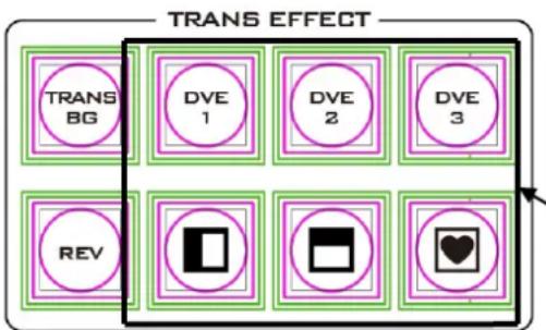
flowchart
graph TD
    A["TRANS BG"] --> B["DVE 1"]
    B --> C["DVE 2"]
    C --> D["DVE 3"]
    E["REV"] --> F["REDACTED Shape"]
    G["Heart Symbol"] --> H["REDACTED Shape with Heart"]
There are 32 different 2D WIPE effects and 3 different 3D WIPE effects to choose from when using the HS-3200 switcher. To select a different WIPE transition, either select a WIPE style in the TRANS EFFECT area of the HS-3200 Control Panel or the Start Item of the OSD Menu (see the table below). Before you make the selection, make sure the TRANS BG and WIPE/DVE buttons are enabled.
| Start | Transition | M/E | 60 | DSK | 15 | FTB | 60 |
| Type | WIPE | ||||||
| Wipe Effects | Wipe | 1 | Soft | 0% | Width | 1% | |
| Border | Luma | 100% | Sat | 80% | Hue | 0 | |
| Position | X | 0% | Y | 0% | |||
| Matte | Luma | 100% | Sat | 80% | Hue | 0 | |
Note: Open the OSD menu by pressing the MENU button in the MENU area of the HS-3200 Control Panel.
To select a WIPE on the OSD menu, navigate to the WIPE option under WIPE EFFECTS and then select a WIPE number. Each WIPE transition also has flexible user options to tailor the look of the transition. All wipes have an optional colour border applied. The wipe border width and colour are also chosen within the menu system.
Soft Value
This value allows the ‘inside’ and ‘outside’ edge softness of the Wipe Border to be controlled. A low value makes a sharp or hard wipe edge. A large value results in a softer or diffused wipe edge.
Width Value
This value determines how wide the actual wipe effect is. A low value makes a narrow wipe. A large value makes a wider wipe.
Hue, Sat and Luma values
The colour of the Wipe Border Matte can also be controlled by adjusting the Hue, Sat and Luma values.
Wipe Position
Certain Wipes, such as the Circle and the Oval Wipes, allow the Wipe position to be controlled.
The X value allows the selected wipe to be offset to the left or right of the screen.
The Y value allows the selected wipe to be offset to the top or bottom of the screen.
REV Button
When the REV Button is OFF the selected WIPE or DVE transition will operate in its default direction only. When the REV Button is ON then the selected transition will operate in the reverse direction.
5.3 Managing Still Pictures
On the HS-3200 Switcher, the user will be allowed to manipulate uncompressed still pictures with Grab and Frame Store functions. In this section, you will also be guided to load the stills saved on the switcher and display them on the monitor.
Each video channel of the HS-3200 has one frame store to which a still can be loaded, and the unit has enough storage space for up to 1000 uncompressed stills.
Grabbing & Saving a Still to Memory
The Grab & Save options of the OSD menu allow new Still Images to be created by grabbing & saving the current Program video frame image to two internal still buffers in the HS-3200.
- Press the MENU button to open the OSD menu (shown below) on the Multiview display.
| Stills | File Type | Still | ||
| Load Still | Load | Still Num 1 | Still 1 | |
| Thumbnail Picture – 1 | Thumbnail Picture | Thumbnail Picture + 1 | ||
| Save Still | Save | Still 1 | Still Num 1 | |
| Delete | ||||
| Grab Still | Grab | Still 1 |
- The Program output is grabbed to a Still buffer (Still 1 or 2) by selecting 'Grab'.
-
The user can look at the Multi Image Preview and decide if this Still should be saved.
-
To save a Still from the currently selected Stills buffer, the user should select a Still number that has not been used yet, and select 'Save'.
- The save process takes about 15 seconds, after which the new thumbnail picture will be shown within the Still display under the chosen still number.
Loading an existing Still from Memory
The Still Load Menu allows stills already stored in the HS-3200 to be loaded to a Still buffer (Still 1 or 2) or an Input buffer (Inputs 1 – 12). Follow the steps below to load the still.
| Files | File Type | Still | ||
| Load Still | Load | Still Num 10 | Still 1 | |
| Thumbnail Picture – 1 | Thumbnail Picture | Thumbnail Picture + 1 | ||
| Save Still | Save | Still 1 | Still Num 10 | |
| Delete | ||||
| Grab Still | Grab | Still 1 |
The Still menu screen (shown above) shows thumbnail pictures of up to 3 saved stills at a time. If there are more than 3 stills stored in the HS-3200 then the Menu Control's up/down arrow buttons can be used to move through the saved stills. The stills are shown in numerical order, and any numbers not used will be blank.
To load a still, simply browse to a Still number and select a still buffer then select 'Load'. The selected still will be loaded into the selected buffer. In the above example, the still buffer will be loaded with the image in memory slot 10.
Deleting a saved Still from Memory
To delete a saved still, select a still number that is no longer required. Select 'Delete' and you will be prompted to confirm the delete. Select 'YES' to remove the still from the switcher's memory and 'No' to cancel the delete.
Note: The deleted still, if pre-loaded to the current Still or Input buffer, will be kept until another still image is selected or grabbed to occupy this buffer.
FS - Frame Store Button
The HS-3200 has twelve video channels and each of these channels has its own Frame Store, making a total of twelve Frame Stores. Each of these Frame Stores can hold one still image. The FS button allows the user to call the still image into the production and toggle between that still image of the Frame
Store and the live video input connected to that same video channel.
How to choose live video input or Frame Store
-
First press and hold down the FS button. The Preset row of input sources will flash green.
-
While still holding down the FS button, press the required input on the Preset row. For example, pressing button 1 switches the video channel to the still picture mode.
- To return to the live video mode, simply press the channel button again.
This selection will also be confirmed on the Multi-view output, with the selected channel showing the live input or frame store image.
Note: Before using the FS function, first make sure the still picture has been loaded to the input video channel. Refer to Section 5.3 for instructions on loading still pictures.
Import Still Images from PC
The Switcher Image Import/Export software (SwitcherImageImEx_vx.x.x.msi) allows the user to import still pictures from the PC to a designated Still number in the switcher. The software installation package can be downloaded from the product page. Features of the Import/Export software are listed as follows:
- Supported file formats are BMP, JPG, PNG, and PIC.
- Minimum resolution is 1280 x 720.
See Chapter 3 for installation instructions and network configuration.
How to use
- After the utility is successfully installed, double click the icon to run the program. Since the program is executed for the first time, it will automatically scan the network and if multiple network interface cards are found, simply select the card that is on the same network as the device.
![Select Network Interface for S... ? × Network Interfaces: [192.168.100.80] Ethernet [192.168.100.80] Ethernet [169.254.217.155] Wi-Fi [169.254.15.235] Local Area Connection* 3 [169.254.32.153] Local Area Connection* 4 [169.254.207.251] Bluetooth Network Connection](/content/2026/05/950367/images/5348b220aba2574ddf4c7c2dbfb1ce13e1cd7f9353b2d1d9443d3d44540d0c26.jpg)
- If the available device is scanned and found, the connection will be automatically established and the Connect Status will show "Connected" (will show Not Connected if disconnected).
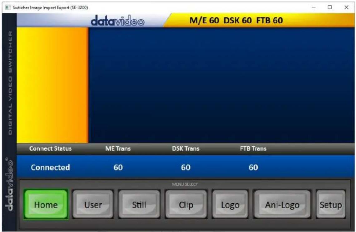
- After clicking the Setup button, you will see the network information as shown below.
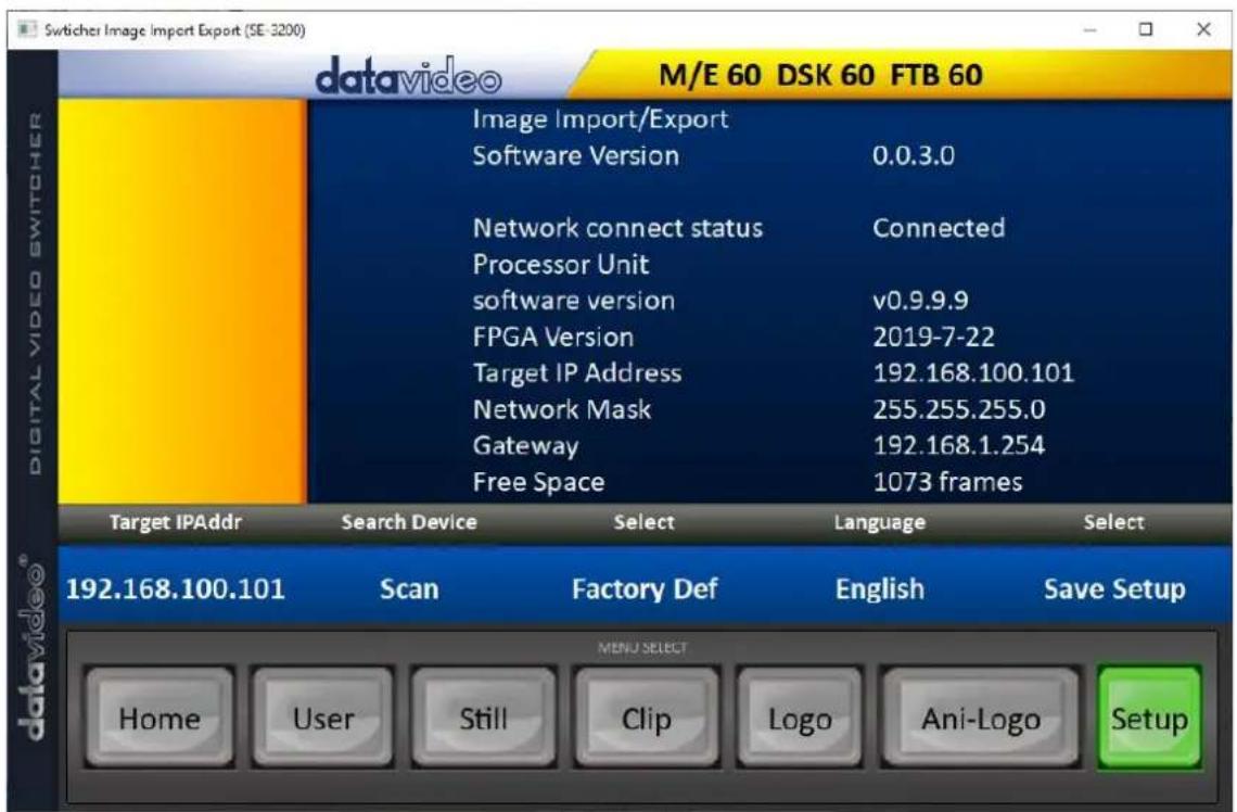
- Click the Still button to view thumbnails of still pictures and import still pictures from your PC.
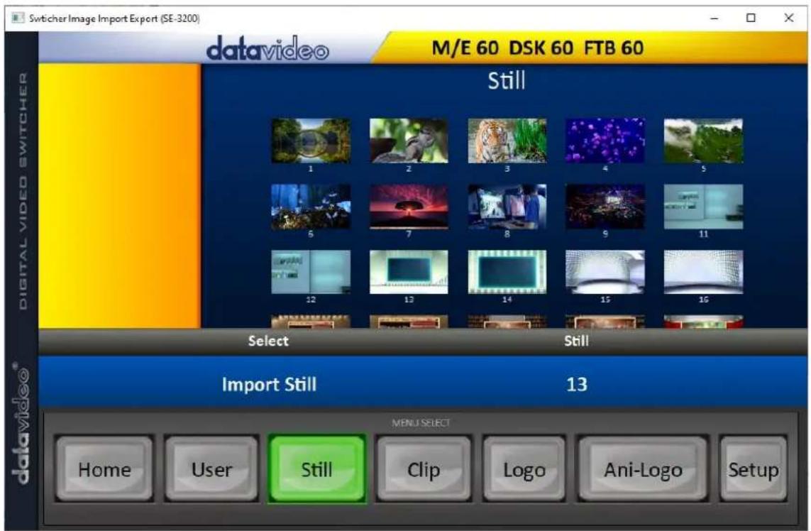
- Click the Still number first and enter a location for storing the still. Then click Import Still and the interface for selecting still files will appear. If the selected picture is not 1120x1080 or 1280x720, the interface shown below will pop up to allow you to crop or zoom in/out the picture.
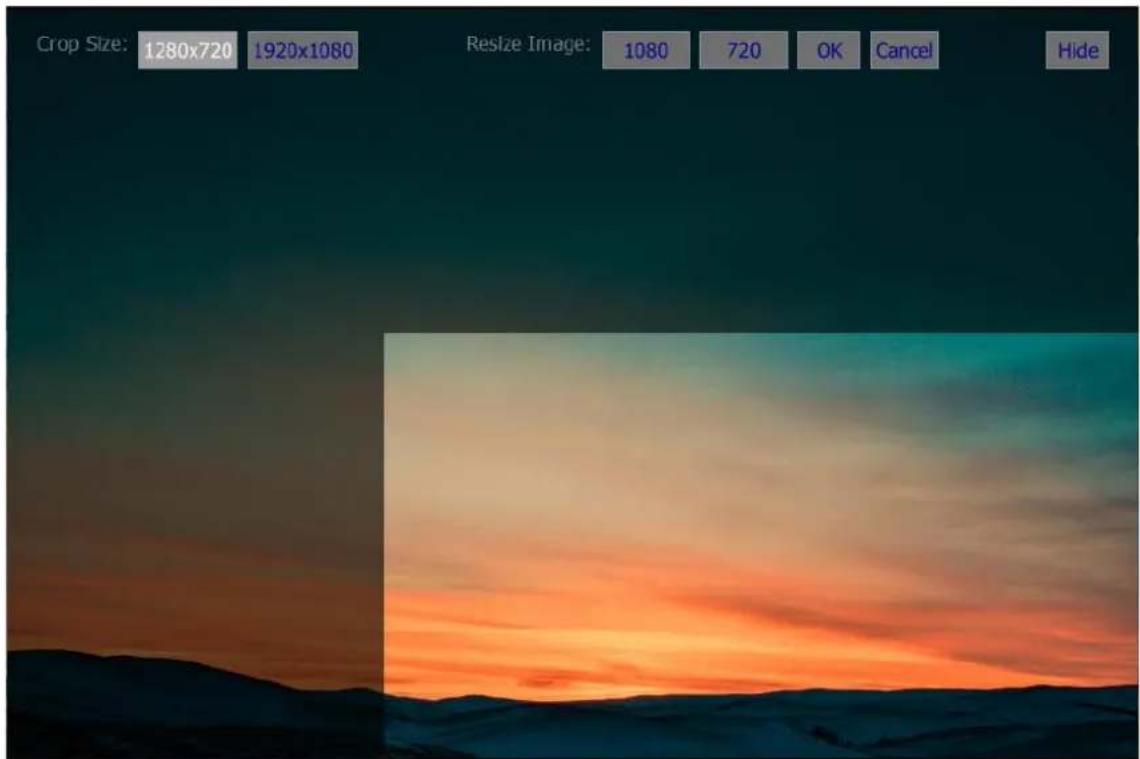
Crop Size: Select the right crop
Resize Image: You will be allowed to select two sizes, large (1080) or small (720), and zoom the picture to 1920 x 1080 or 1280 x 720.
OK: Apply the crop and start the import.
Cancel: Cancel the selection
Hide: Hide the interface
-
After the right crop is selected or the resolution is correctly configured, click OK to start importing the still picture to the switcher.
-
To confirm that the still picture is imported successfully, click the Still button on the MENU SELECT pane to view the thumbnails. OSD menu is another way to confirm the import, simply go to Files -> File Type → Still.
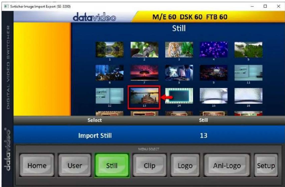
5.4 Performing a Stinger Transition
The Stinger Transition Effect is basically an animated effect added during transition of two video sources. The animated effect is generated by a clip which consists of a series of sequential files in bmp, jpg, png or pic format. This type of transition is very popular in sports productions for transitioning in and out of instant replays.
In this section, we will explain how to build and perform stinger transitions.
Loading a Clip from Memory
In Clip, use the Up/Down arrow buttons on the physical keyboard of the switcher to browse the clip files. Once "Load" is pressed, the selected clip will be loaded into the clip buffer and replace the previously loaded clip.
| Files | File Type | Clip | ||
| Load Clip | Load | Clip 0 | Clip Settings | |
| Thumbnail Clip - 1 | Thumbnail Clip | Thumbnail Clip + 1 | ||
| Clear Clip | Delete Clip |
Note: The HS-3200 comes with pre-loaded clip files. The HS-3200 also allows the user to import customized clip files. It is recommended to use 32-bit with Alpha png format.
Preview of clip videos is below the "Load Clip" sub-option. You can preview three clip videos at the same time.
After the clip video has been successfully imported, to enable the Clip (Stinger) transition mode, simply turn ON the Clip button.
Importing the Clip for Stinger Transition Effect from PC
On the HS-3200, besides using the existing clips on the machine, you are also allowed to import your own clip (a series of bmp/png/jpg/pic files) to the HS-3200 from the PC using the Switcher Image Import/Export utility. Simply select one of the sequential files numbered by the last five digits of the file name and the utility program will start linking all images (from the first selected file to the last) up into a sequential animation file. The optimal resolution is 1920x1080.
Instructions for importing the clips are provided below:
Click the Clip button on the MENU SELECT pane.
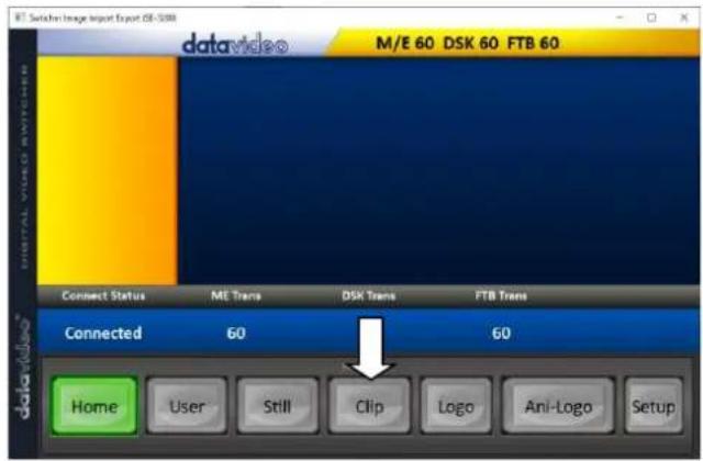
The clip number allows you to select a location where you can save the clip. To import a clip from the computer into the HS-3200, select Import Clip.
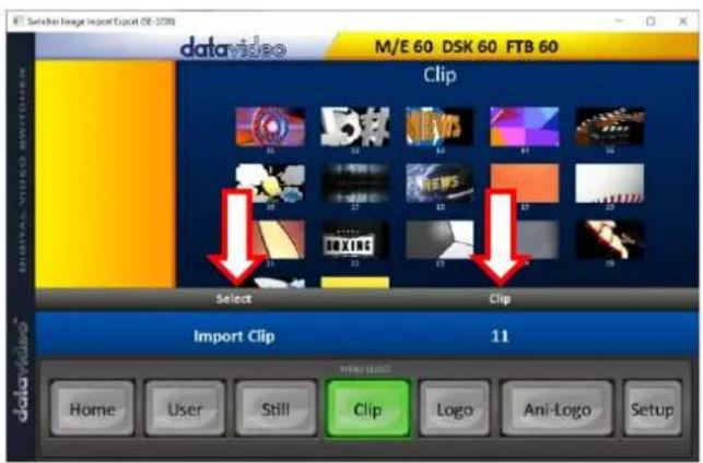
Tip: The Switcher Image Import/Export utility does the conversion from bmp/png/jpg to the .pic file format automatically. All you need to do is to give the utility a starting fi location and it will give the utility an idea where to start linking all images up into a sequential animation file.
Importing Clips
Select "Import Clip" will open a file browser window. Browse to the directory where your clip files are saved and then select the file at the zeroth location, in our example on the right, the file name is frame-000.png.
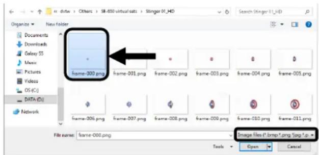
Click Open to start the clip import. If your files are not the .pic format, they will be automatically converted to .pic format by the Switcher Image Import/Export utility first.
After the file conversion, the clip import will then start. After the import is complete, the progress dialog will be automatically closed.
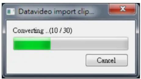
Note: Clip Conversion and Clip Import have progress dialogs that show progress & number of frames done. These dialogs also have a cancel button which allows the user to cancel the import at any stage. If the import is cancelled, then the partially imported data will be deleted.
How to Create the PNG Sequence for Stinger Transition Effect
Adobe After Effects is a motion graphics application that can be used for creating the clip file for stinger transition effect. After the clip file is created, there are two ways to convert the file to the PNG sequence format readable by the HS-3200 switcher in Adobe After Effects. In this section, we will show you how you can create the PNG sequence for the Stinger transition effect.
Adobe After Effects
-
Click File → Export → Add to Render Queue (or alternatively, you can also click Composition → Add to Render Queue).
-
The Render Queue will be displayed in the bottom pane.
-
Click Output Module and on the Main Options window, click the Format dropdown list and select PNG Sequence.
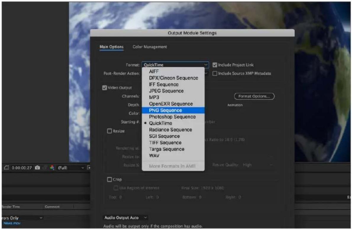
- Click the Channels dropdown list and select the "RGB + Alpha" option.
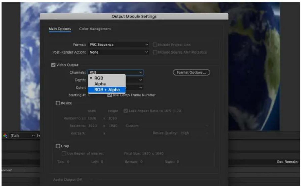
- Click "Output To" and then change the location where your files are rendered. Click Render after that.
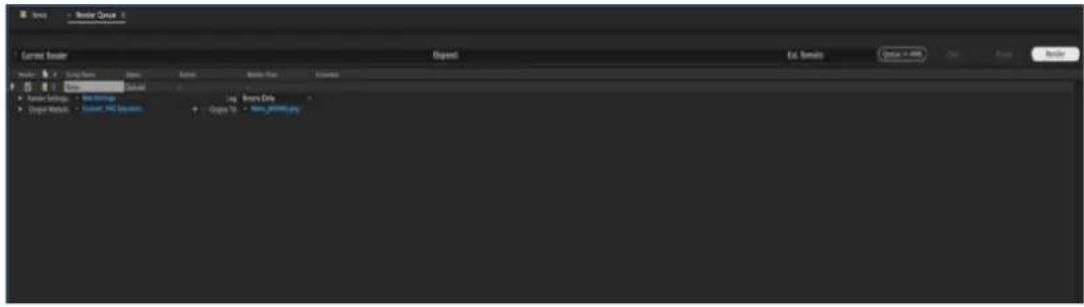
The next section outlines the file conversion procedure using the Media Encoder CC.
Adobe Media Encoder CC
- Click Composition → Add to Media Encoder Queue (or alternatively, you can also click File → Export → Add to Media Encoder Queue).
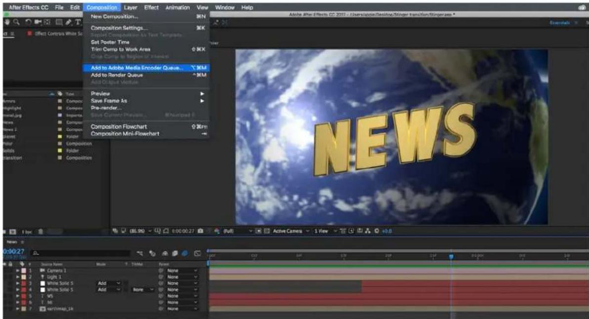
- Click blue fonts in Format/Preset fields to open the "Export Settings" window.
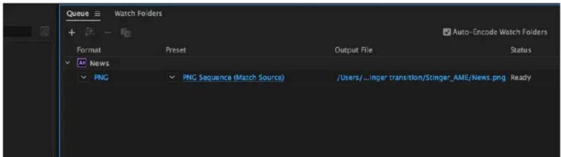
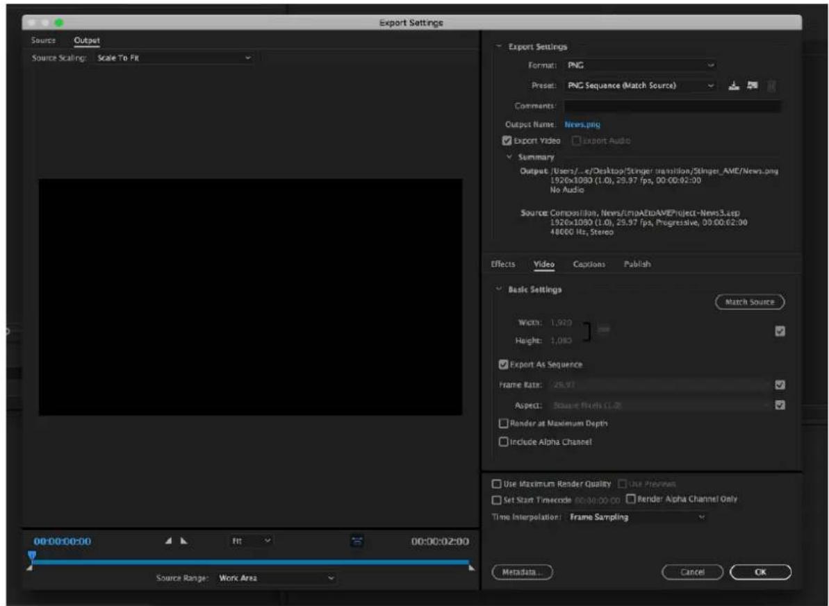
- Click the Format dropdown list and then select PNG.
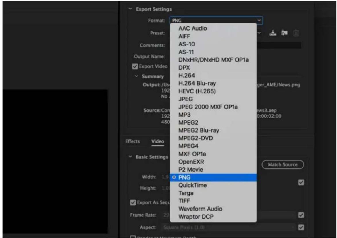
- Click the Preset dropdown list and select "PNG Sequence with Alpha."
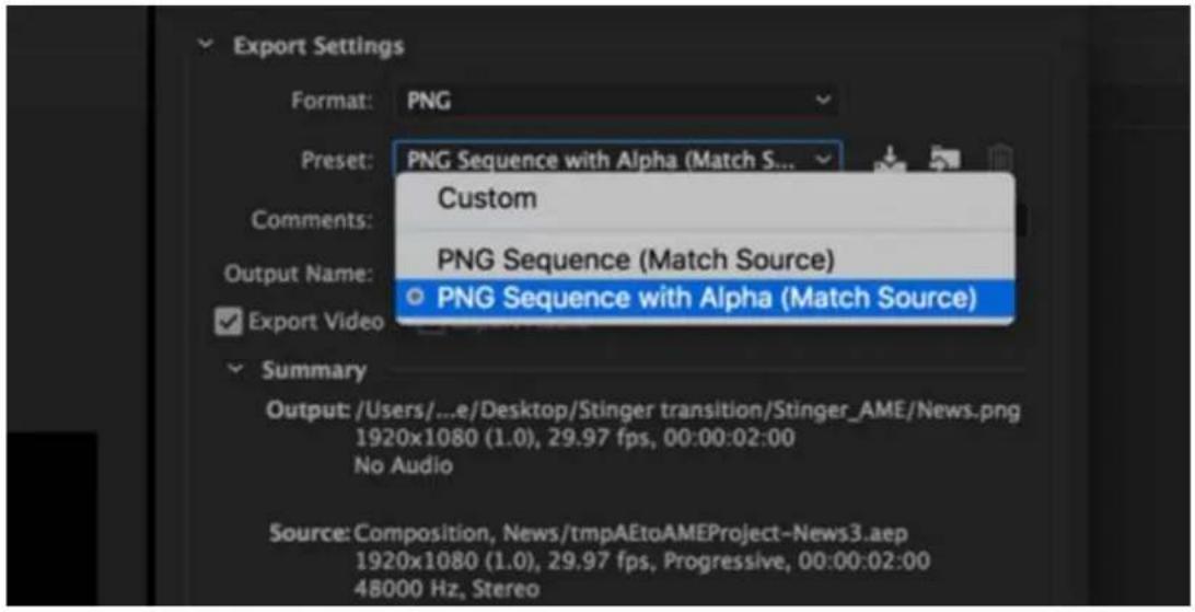
- Make sure "Export As Sequence" and "Include Alpha Channel" are checked and then click OK.
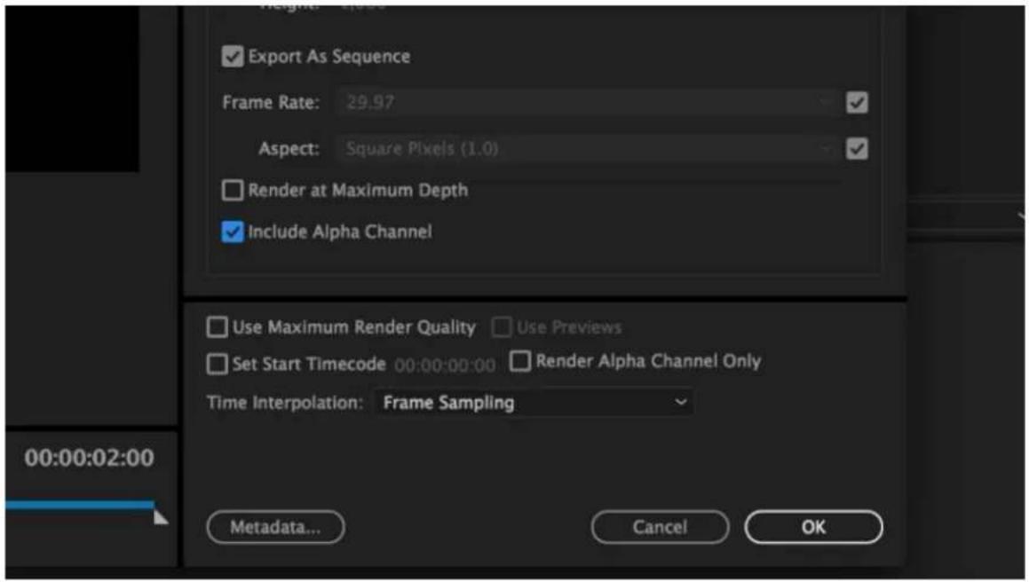
- Select "Output File" to choose the render files destination. Click the green button to render.
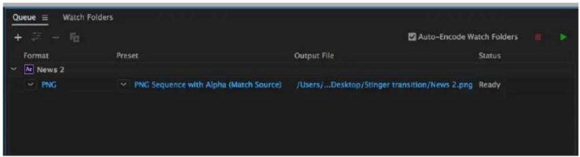
- Once completed, the status will display "Done."
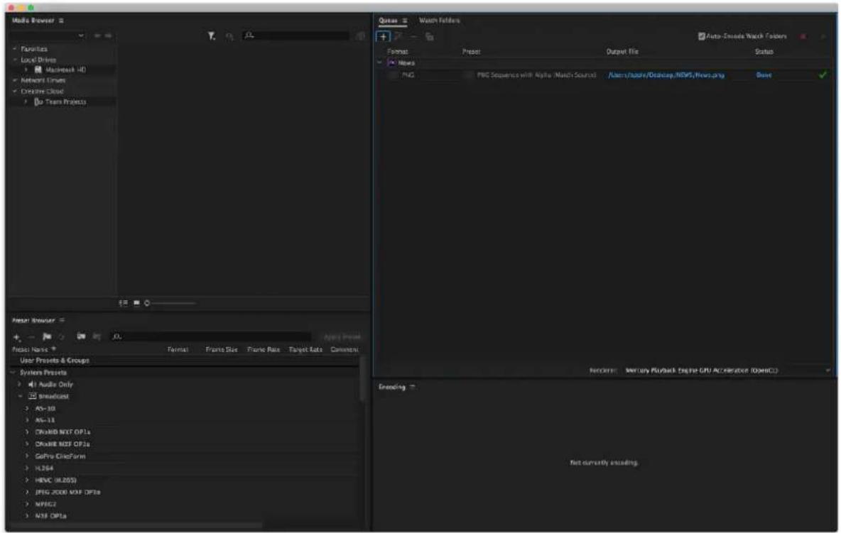
After the sequential files are created and ready, see the following sub-sections on how you can import the Clip file to the switcher.
Important things to note while creating Stinger Transition Effects
When using Datavideo's HS-3200 Multi-Channel Switcher to design and create the Stinger Transition Effects, in addition to being creative, there are a few things that you need to take into account of.
- Length limit of the stinger transition animation
The length of a good stinger transition animation should be approximately 0.5 to 2 seconds.
- The HS-3200 allows a maximum of 200 image files in an animation sequence
The number of image files will determine the length of stinger transition time.
- While designing the animation, it is best to have an image that fills up the entire frame to create a satisfactory visual effect (please see the images below).

natural_image
Two male professionals in suits seated in front of a colorful digital screen with a globe graphic (no visible text or symbols)
5.5 Enabling Still Logo
The HS-3200's logo function places a logo layer on your video. In this section, we will show you how to import still logo image to the switcher, load still logo image on the switcher as well as enabling the loaded still logo on Preview and Program Out.
The HS-3200 has enough storage space for up to 1000 uncompressed still logo pictures.
Loading an existing Logo from Memory
The HS-3200 allows the user to load still logo from the machine's memory to the logo buffer (Logo 1 or 2), then press either Logo 1 or Logo 2 button to enable the loaded logo on both the Preview and Program Out. Follow the steps outlined below to load the desired still logo from memory.
| Files | File Type | Logo | ||
| Load Logo | Load | Logo 13 | Logo 1 | |
| Thumbnail Picture – 1 | Thumbnail Picture | Thumbnail Picture + 1 | ||
| Clear Logo | Delete Logo | |||
| Logo 1 | X -37% | X 24% | ||
| Logo 2 | Y 0% | Y 0% |
On the still logo menu, you should find a thumbnail view of three logos. Use the up/down arrow buttons to browse all other logos which are shown in numerical order. Black thumbnails are unused memory slots.
To load a still logo, simply browse to a still logo number and select a logo buffer then select 'Load'. The selected still logo will be loaded into the selected buffer. In the above example, logo 1 will be loaded with the logo saved in memory slot 13.
To adjust the logo position, simply change the X and Y values of the respective logo buffer which can be found at the bottom of the Logo menu.
Selecting "Clear Logo" clears the logo buffer. Selection of "Delete Logo" removes the logo from the selected memory slot.
Importing Still Logo from PC
The Switcher Image Import/Export software (SwitcherImageImEx_vx.x.x.msi) allows the user to import still logos from the PC to a designated memory slot of the switcher. The software installation package can be downloaded from the product page.
Note: A standard still logo is basically a still picture with an aspect ratio limited to 480x720.
See Chapter 3 for installation instructions and network configuration.
How to use
- Open the Switcher Image Import/Export Program and make sure the Connect Status shows "Connected" (shows Not Connected if disconnected).
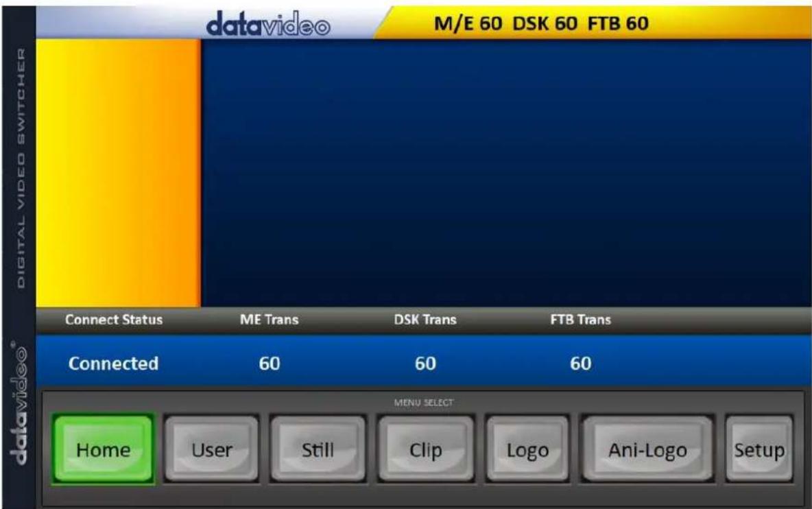
- Clicking the Logo button to view logo thumbnails and import logos from your PC to the switcher.
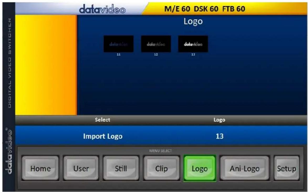
- Click "Logo" number then enter a memory slot number. Click "Import Logo" to open the file browser window and browse to the file that you would like to import.
- Select the logo file that you would like to import. Note that the aspect ratio is limited to 480x720.
- Check on the program's Logo page to make sure that the logo has been imported successfully.
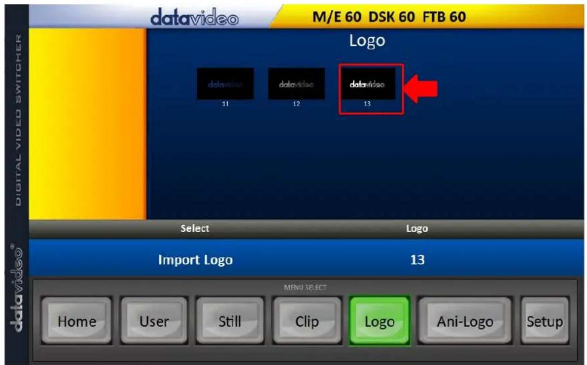
- After successfully importing the logo into the switcher, you will then be able to start loading the new logo to the buffer. To enable the logo on Preview and Program Out, press the Logo button.
5.6 Enabling Logo Animation
The HS-3200's logo animation function places an animated logo layer on your video. Each animated logo consists of a series of 120 sequential files in bmp, jpg, png or pic format. Every image file is limited to an aspect ratio of 480x270.
In this section, we will show you how to import animated logo to the switcher, load animated logo on the switcher as well as enabling the loaded animated logo on Preview and Program Out.
Note: The HS-3200 has enough storage space for up to 1000 uncompressed animated logo.
Loading an existing Ani-Logo from Memory
The HS-3200 allows the user to load ani logo from the machine's memory to the logo buffer (Logo 1 or 2), then press either Logo 1 or Logo 2 button to enable the loaded ani logo on both the Preview and Program Out. Follow the steps outlined below to load the desired ani logo from memory.
| Files | File Type | Ani Logo | ||
| Load Ani Logo | Load | Ani Logo 13 | Logo 1 | |
| Thumbnail Picture – 1 | Thumbnail Picture | Thumbnail Picture + 1 | ||
| Clear Ani Logo | Delete Ani Logo | |||
| Logo 1 | X -37% | X 24% | ||
| Logo 2 | Y 0% | Y 0% |
On the ani logo menu, you should find a thumbnail view of three animated logos. Use the up/down arrow buttons to browse all other animated logos which are shown in numerical order. Black thumbnails are unused memory slots.
To load an animated logo, simply browse to an ani logo number and select a logo buffer then select 'Load'. The selected animated logo will be loaded into the selected buffer. In the above example, logo 1 will be loaded with the animated logo saved in memory slot 13.
To adjust the animated logo position, simply change the X and Y values of the respective logo buffer which can be found at the bottom of the Ani Logo menu.
Selecting "Clear Logo" clears the logo buffer. Selection of "Delete Logo" removes the animated logo from the selected memory slot.
Importing Animated Logo from PC
The Switcher Image Import/Export software (SwitcherImageImEx_vx.x.x.msi) allows the user to import animated logos from the PC to a designated memory slot of the switcher. The software installation package can be downloaded from the product page.
Note: Each animated logo consists of a series of 120 sequential files in bmp, jpg, png or pic format. Every image file is limited to an aspect ratio of 480x270.
See Chapter 3 for installation instructions and network configuration.
How to use
- Open the Switcher Image Import/Export Program and make sure the Connect Status shows "Connected" (shows Not Connected if disconnected).
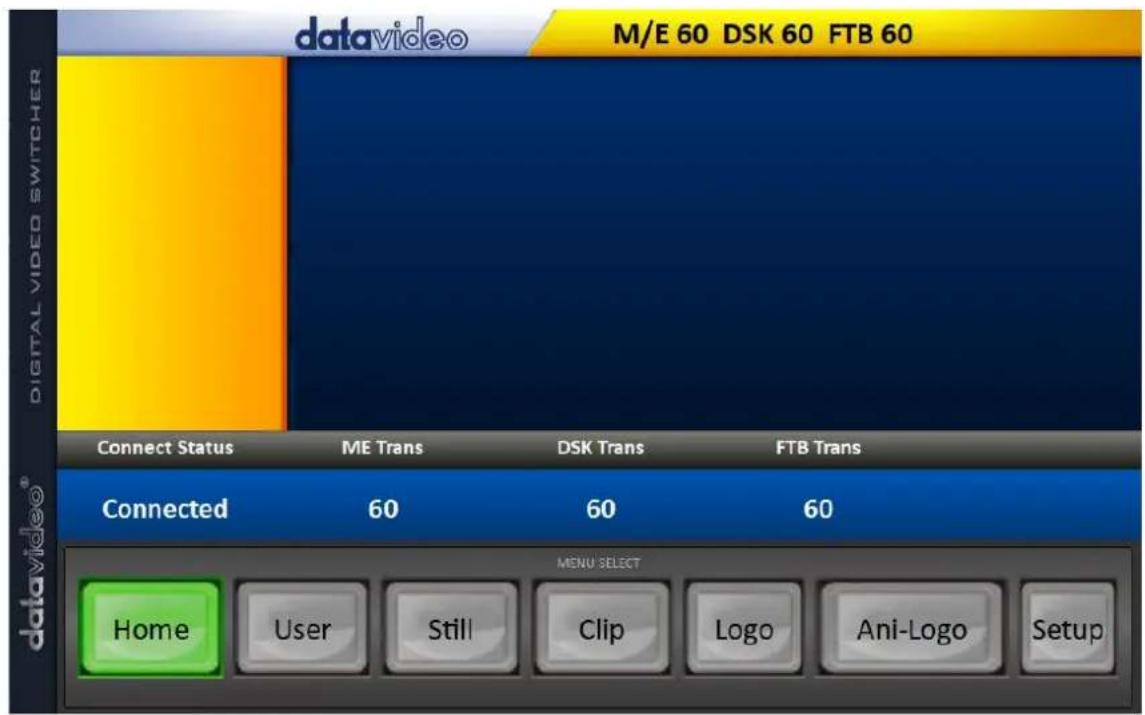
- Clicking the Ani-Logo button to view animated logo thumbnails and import animated logos from your PC to the switcher.
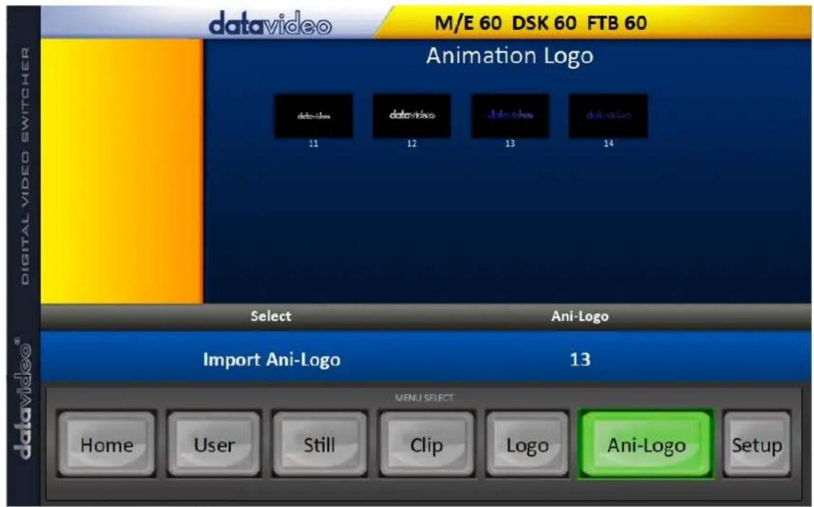
- Click "Ani Logo" number then enter a memory slot number. Click "Import Ani-Logo" to open the file browser window and browse to the file that you would like to import.
- Select the animated logo file at the zeroth location so upon file import, the program will then link all images up into a sequential animation file. If your files are not the .pic format, they will be automatically converted to .pic format by the program first.
- Check on the program's Ani Logo page to make sure that the animated logo has been imported successfully.
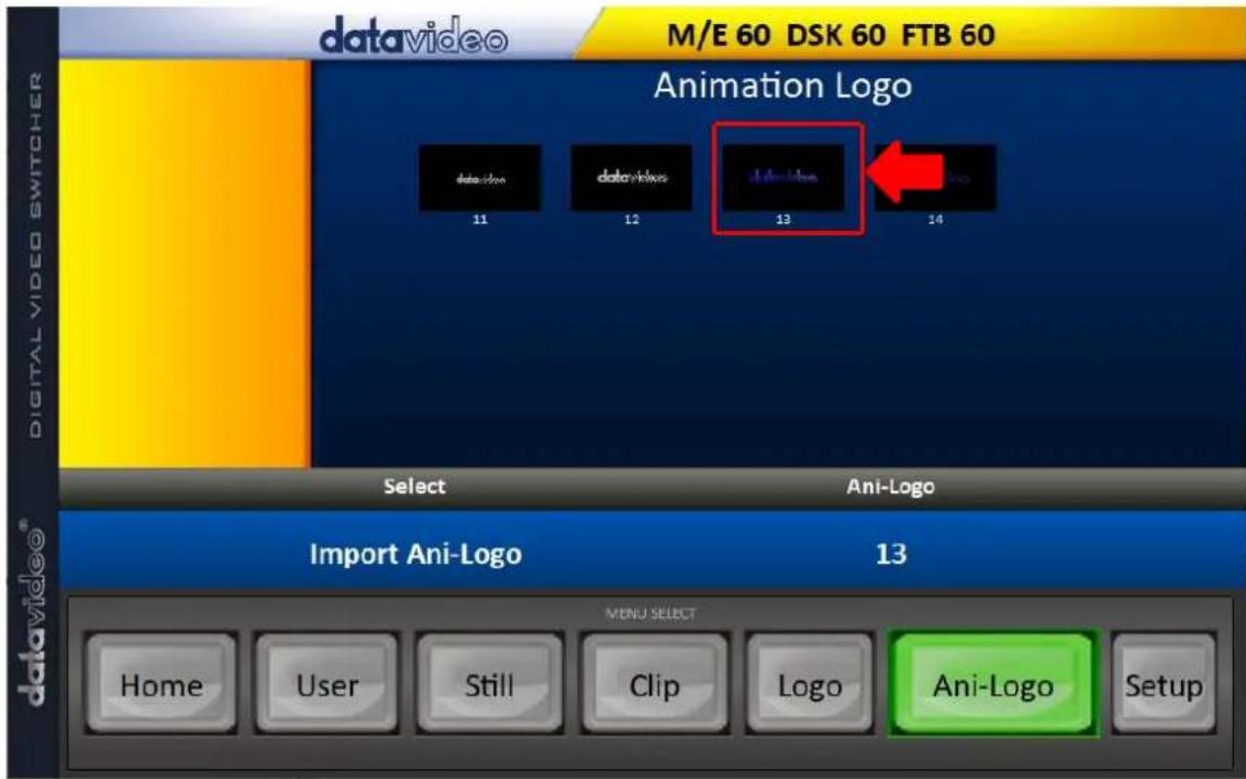
- After successfully importing the animated logo into the switcher, you will then be able to start loading the new animated logo to the buffer. To enable the animated logo on Preview and Program Out, press the Logo button.
Chapter 6 Advanced Operation
The HS-3200 is a High Definition Digital Video Switcher. As well as mixing video and audio sources, it has additional functions such as Picture In Picture (PIP), DSK, LUMA KEY, Chroma Key and Logos.
Before attempting to use the HS-3200's PIP, DSK LUMA KEY and LOGO functions it may help to first understand the order of the video layers at the HS-3200 Program (PGM) outputs.
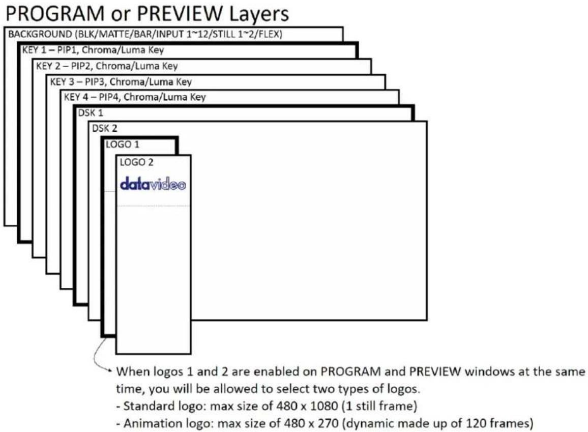
The Background video layer is the normal video layer (black screen, color matte, color bars, inputs 1-12, still pictures 1 and 2 or Flex™ sources) when mixing and switching with the HS-3200. It occupies the whole screen area of the Program output. This layer can be hidden or partly hidden by the PIP, DSK and LOGO layers in front of it.
The Key 1 layer (PIP1, chroma key or luma key) does not occupy the whole screen and is shown in front of the Background video layer when enabled.
The Key 2 layer (PIP2, chroma key or luma key) does not occupy the whole screen and is shown in front of the Background video and Key 1 layers when enabled.
The Key 3 layer (PIP3, chroma key or luma key) does not occupy the whole screen and is shown in front of the Background video, Key 1 and Key 2 layers when enabled.
The Key 4 layer (PIP4, chroma key or luma key) does not occupy the whole screen and is shown in front of the Background video, Key 1, Key 2 and Key 3 layers when enabled.
In some setups the Key image can be hidden behind other key images. This is not a fault. Change the position or size of the Key image if required.
The DSK 1 layer can occupy the whole screen. If set up incorrectly this layer can stop the video layers behind it from being seen properly. Re-adjust your DSK 1 settings or switch off the DSK1 function on the HS-3200 to restore the video behind it.
The DSK 2 layer can occupy the whole screen. If set up incorrectly this layer can stop the video layers behind it from being seen properly. Re-adjust your DSK 2 settings or switch off the DSK2 function on the HS-3200 to restore the video behind it.
The logo layer is the uppermost layer. If standard logo (still) is chosen, the maximum logo size will be restricted to 480 x 1080. If animation logo (dynamic) is chosen, the logo will be confined within 480 x 270.
Note: Where possible prepare and position the upper video layer elements in advance of the live production starting to avoid them appearing on the program output incorrectly.
Most broadcast networks have guidelines and advice on the use of video, images, music, logos and on screen text so it is best to check beforehand when planning a production. Do not use copyright protected content until you have the relevant permissions. Information on royalty free video, images and music is widely available, speak to your local dealer or search for advice on the internet.
6.1 Picture-in-Picture and Downstream Key
The Picture in Picture (PIP) feature of the Key 1, Key 2, Key 3 and Key 4 layers can be used for displaying a smaller secondary image in front of the background video layer. This smaller PIP image can be resized, cropped, repositioned and even keyed by the user to avoid an important part of the background video layer being covered by it.
The Down Stream Key layers (DSK 1 & DSK 2) are placed on top of all the previous layers. These layers are typically used with Character Generator inputs for displaying titles, graphics, lower thirds, clocks and logos. Datavideo offer several Character Generator products (additional purchase) such as TC-200, CG-250, CG-350 and CG-500. If set up incorrectly these DSK layers can also stop the video layers behind them from being displayed properly.
The HS-3200 has six dedicated keyers, Key1, Key2, Key3, Key4, DSK 1 and DSK 2. All six keyers can be active simultaneously.
Picture-In-Picture
In this example, we are supplying the HS-3200 with an HD-SDI live video signal to input 2; this is selected on the Program row. We have also assigned a STILL image to input 6. This still image, selected on the Keyer sub menu, will be displayed in the PIP window.
Note: See Section 5.3 for assigning a STILL image to input 6.
On the HS-3200 Control Panel / Keyboard there are eight KEYER keys. These are labelled Program and Preview. The upper KEYER keys relate to activating Picture-In-Picture images on the Program outputs. The lower KEYER keys relate to activating Picture-In-Picture images on the Multiview or Preview outputs. Before activating
Picture-In-Picture images on the output image, you should first set these KEYER keys to PIP mode.
Assigning a video source to a PIP window
On the Keyer sub menu you can assign a selected input to the chosen PIP video layer.
- Open the Keyer sub menu and in the Keyer Ctrl option, set Key 1 to the desired Key (Luma, Chroma and Linear) and PIP mode as shown below.
| Keyer | Keyer | Key 1 | Normal | |
| Keyer Ctrl | Luma | PIP | Opac 100% | |
| Lift 0% | Gain 1.0 | Invert Off | ||
| Key Source | Input 1 | Fill Black | ||
| Mask | Left 0% | Right 0% | ||
| Top 0% | Bot 0% |
- In the Key Source option, assign an input source.
- Activate PIP window on the Preview or Program output by pressing Key 1 PVW or Key 1 PGM button so that you can adjust the PIP window while viewing the changes made.
- Open the P-in-P sub menu and adjust the PIP window settings (positions, border, shade matte and crop). For descriptions of the parameters, refer to the section on P-In-P for more details.
| P-in-P | Keyer | Key 1 | Fine | Normal | |||
| Position | X | 20% | Y | 10% | Size | 40% | |
| Border | Normal | ||||||
| Luma | 100% | Sat | 80% | Hue | 0 | ||
| Width | 2% | Soft | 0% | Opac | 100% | ||
| Shade Matte | Luma | 100% | Sat | 80% | Hue | 60 | |
| Shade Soft | 2% | Shade Pos | 50 | Direction | 35 | ||
| Crop | Left | 0% | Right | 0% | Size | 0% | |
| Top | 0% | Bot | 0% | Soft | 0% | ||
Assigning a video source to a PIP window using shortcut keys
In addition to assigning a video source to a PIP window on the OSD MENU, the user can also use shortcut keys to easily switch between different PIP image sources. Press and hold KEY 1-4 PGM buttons, and the program and preview rows will start flashing. Press the program row buttons to switch the PIP image source.
Character Generator
The built-in TC-200 Title Creator allows you to linear key the CG text or graphics over the live video. However, please note that the following hardware restrictions apply when using this feature.
- The built-in title overlay system (TC-200) works better with ATI and Intel VGA graphics cards.
- Compatibility issue such as color difference may occur when used with NVIDIA graphics cards.
Simply connect the laptop, with CG software installed, to one of the HDMI inputs (inputs 9 to 12) of the switcher. Ensure that your input image or video resolution matches the switcher's resolution set in OSD menu → Setup → Standard.
Then follow the steps below to set up the built-in TC-200
- Connect the laptop to one of the HDMI ports of the HS-3200 switcher using an HDMI cable. In this example, we will be using HDMI port 9 for illustration purpose.
- Open CG-250 on the laptop and create a CG image that can then be sent to the HS-3200 via the built-in TC-200.
- Switch ON the HS-3200's power button and after the boot up is complete, the Multiview should be displayed on the connected monitor.
- On the Multiview, Input 9 window should display the CG image.
- Press the "MENU" button on the HS-3200's control panel to open the OSD menu on the Multiview display and then select the "Inputs" sub menu.
- Select "Input 9" from the Input option and enable TC-200 mode by turning on TC-200 Md.
| Inputs | Input | Input 9 | Mode | Live | Mode | TC-200 Md | |
| Proc Amp | Black | 0% | White | 100% | Chrom | 1.0 | |
| Audio | Gain | 0 dB | Delay | 0 ms | |||
| Crosspoint | Input 9 | ||||||
| Audio XPT | Off | ||||||
-
Move to the "Keyer" sub menu.
-
Select "DSK 1 or 2" from the Keyer option and set Key and Fill Sources to Input 9.
| Keyer | Keyer | DSK1 | Normal | ||||
| Keyer Ctrl | Linear | Split | Opac | 100% | |||
| Lift | 0% | Gain | 1.0 | Invert | Off | ||
| Key Source | Input 9 | Fill | Input 9 | ||||
| Mask | Left | 0% | Right | 0% | |||
| Top | 0% | Bot | 0% | ||||
- Locate DSK buttons on the switcher's control panel then depending on the settings selected at Step 8, press DSK 1 or 2 button to open your CG graphics on either of the preview and program windows or both.
DSK Preview and DSK Program



On the HS-3200 Control Panel / Keyboard there are four DSK keys. These are labelled Program and Preview. The upper DSK1 and DSK2 keys relate to activating Down Stream Keying on the Program outputs. The lower DSK1 and DSK2 keys relate to activating Down Stream Keying on the Multi-view or Preview outputs.
To display the CG subtitle configured previously, simply press the DSK 1 PGM or DSK 1 PVW button to enable the downstream key on the PGM or PVW screen.
6.2 Placing text on the video using luma key
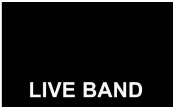
The HS-3200 allows the user to place a logo or text image (ideally black and white) on the video using the luma key function. First of all, create a 1920x1080 (16:9) text image against a black or white background on a laptop. Once the text image is created, please follow the steps outlined as follows to insert the text image.
Note: If the text image is dark, choose a white background; if the text image consists primarily of bright colors, choose a black background.
- Connect the laptop to the switcher's HDMI Input Port 9.
-
Press the MENU button to open the OSD Menu on the Multiview display.
-
Select Keyer to open the Keyer sub menu.
| Keyer | Keyer | Key 1 | Normal | |||
| Keyer Ctrl | Luma | Self | Opac 100% | |||
| Lift 0% | Gain 1.0 | Invert Off | ||||
| Key Source | Input 9 | Fill Black | ||||
| Mask | Left 0% | Right 0% | ||||
| Top 0% | Bot 0% | |||||
-
Select Key 1.
-
In the Keyer Ctrl option, select "Luma" and "Self" to apply luma keying effect to the connected input. The luma key removes the background, in this case, the black component of the image.
-
In this example, the text image is against a black background so reduce the Lift value to remove the black background. Descriptions of the corresponding parameters are described below:
- Lift (0 – 100%) adjusts the dark/black areas of the key image. Reducing the value of Lift will make dark areas of the key image more transparent. The background image will be showing only through the transparent areas.
- Gain (0.0 – 16.0) adjusts the light/white areas of the key image. Increasing the value of Gain will make light areas of the key image more solid. The background image will be showing only through the transparent areas.
- Opac (0 – 100%) adjusts the transparency of the overall foreground image, which is the text in this example. Increasing the value of Opacity will make the overall key image less transparent.
- Invert (On/Off) sets the luma key color; luma key color is white if turned ON and black if turned OFF.
-
Set the "Lift" to 100% if the background is in total black.
-
Opaque logo can be created by setting the "Opac" parameter to 100%. Set "Opac" to 100% if an opaque logo is desired. Semi-transparency effect can be generated by setting the "Opac" parameter to a value between 0 and 100%.
-
Under the Source option, select an input source to which the luma key settings will be applied. In this example, select "Input 9" since this is the port to which the laptop is connected.
Note: Since "Self" is chosen, Fill input will be ignored.
-
Exit the menu after the luma key settings are properly configured.
-
Press the Key 1 PGM or Key 1 PVW button to place the text image on the Program screen or the Preview screen respectively.
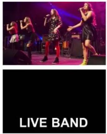
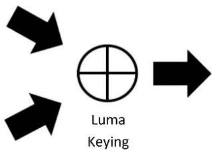
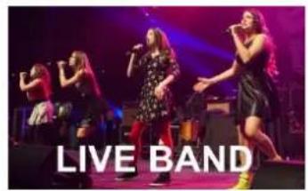
6.3 Insertion of People onto Backgrounds (Chroma Key)
The Chroma Key feature of the HS-3200 is easy to use. Typical Blue and Green screen studios can be quickly incorporated into an HS-3200 production.
The following is a quick overview of Chroma Key basics.
The camera, backdrop and lighting all play an important role in producing the optimal Chroma Key result. Although the HS-3200 is equipped with excellent keying controls, it is best to start with a good keyable image.

natural_image
Man in business suit standing with arms crossed against a solid green background (no text or symbols visible)A good foreground image helps produce a good key
Three chip/Three sensor camera
We strongly recommend the use of a three chip or three sensor camera for Chroma Key shooting. If the camera has three chips or sensors then this usually means good colour separation within the camera. The optics on these cameras are usually better too. The extra image clarity and the good colour separation help improve the quality of the subsequent keying with the camera's output.
White Balance the Camera
White Balance is extremely important after setting up a chroma key studio. The camera must be correctly white balanced to minimize the subject picking up any colour cast (green or blue) from the background. Of course the white balance settings will vary according to the type of lighting you are using, but neutral whites and good skin tone colour are the all-important targets.
To set the white balance you will need a white reference card (or a sheet of white paper). Focus the camera on the reference card and light it evenly using the main light. Set the camera's iris / aperture so that the card is correctly exposed. Use the Auto White Balance (AWB) function, or set the white balance manually so that the card appears white. If you are
in any doubt about how to white balance your camera, please refer to your Camera's instruction manual for more details.
Lighting
Lighting of your chosen green or blue backdrop is extremely important; the more even the lighting on the backdrop the better the finished result. Lighting setups for the foreground subject will vary according to the effect that you want. For chroma keying backdrops, balanced even lighting with no hotspots or shadow areas is the aim. The easiest way to achieve balanced Chroma key lighting is with a lighting setup that looks similar to this:
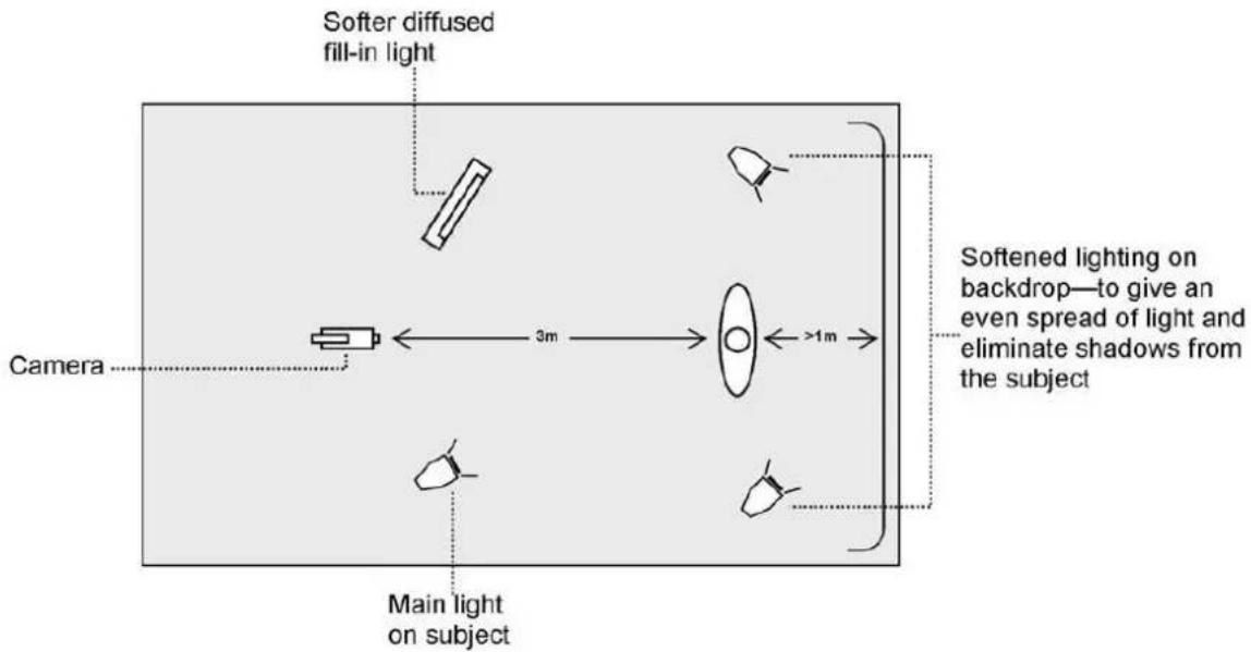
In the diagram, you will see that we recommend a minimum of four lights and we keep the subject more than 1m away from the backdrop. It is always easier to get more even lighting if the subject is farther away from the backdrop (no shadows). The foreground lighting on the subject will also vary according to the effect that you are looking for.
After the studio set up is complete, connect the camera shooting the speaker on a green backdrop to the SDI Input 1 at the rear of the switcher. To configure the settings that will be used for chroma keying, press the MENU button on your HS-3200 control panel to open the OSD menu on the monitor. Follow the steps below to configure the chroma key settings.
- Open the Keyer sub menu and select Key 1.
| Keyer | Keyer | Key 1 | Normal | ||||
| Keyer Ctrl | Chroma | Self | Opac | 100% | |||
| Lift | 0% | Gain | 1.0 | Invert | Off | ||
| Key Source | Input 1 | Fill | Black | ||||
| Mask | Left | 0% | Right | 0% | |||
| Top | 0% | Bot | 0% | ||||
- Select “Chroma” and “Self” under “Keyer Ctrl” and then select the camera source under “Key Source.” In this example, we have selected Input 1, which corresponds to the SDI Input 1 at the rear of the switcher and therefore the port to which the camera is connected.
- Adjust the left, right, top and bottom values of "Mask" to set the chroma key range according to green or blue backdrop size.
- Open Chroma Sub Menu and adjust the corresponding chroma key parameters. Again in this example, we have selected Input 1, which corresponds to the SDI Input 1 at the rear of the switcher.
Note: Selection of CK Auto automatically calculates the best Hue & Luma values for the current Keyer source.
| Chroma | Keyer | Key 1 | Normal | ||||
| Key Source | Input 1 | ||||||
| Key Tie | On | Input 6 | |||||
| CK Setup | CK Auto | Hue | 110 | Luma | 80% | ||
| K Range | 160 | K Fgnd | 10% | K Bgnd | 20% | ||
| Hi-Light | 0% | Lo-Light | 0% | Bg-Supp | OFF | ||
| Left | 0% | Right | 0% | Soft | 0% | ||
| Mask | Left | 0% | Right | 0% | |||
| Top | 0% | Bot | 0% | ||||
The chromakeying parameters are described below:
- Hue: This parameter adjusts the color of the chroma key. A typical green screen value will be around 120. Blue screen value will be around 240.
• Luma: The Luma value relates to how bright or dark the selected key colour or hue is. - K Range (Key Range): Key Range sets the range of hues or colors (0 – 360 degrees) that closely match the background color to be keyed. The user can start with a value of 120 degrees and this value can be fine-tuned up or down depending on the setup of the green or blue screen studio.
- K Fgnd (Key Foreground): Key Foreground adjusts the performance of the chroma key in light or white areas. Apply more Key Foreground if the light areas are becoming too transparent.
- K Bgnd (Key Background): Key Background adjusts the performance of the chroma key in dark or black areas. Apply more Key Background if the dark areas are becoming too transparent.
• Hi-Light: Hi-light boosts the foreground key in high luminance area. - Lo-Light: Lo-light boosts the foreground key in low luminance area.
-
Bg-Supp: Turn ON Background Suppress removes the Luma (Brightness) of the background from the final image. If the Chroma Key Output is showing Light Edges, then the Bgnd suppress can be used to suppress any background Luma that is showing through on these edges.
-
After Chroma Key configuration is complete, close the OSD menu and simply press KEY 1 PGM or KEY 1 PVW button on the switcher's control panel to place the speaker on PGM or PVW Screen as shown in the diagram below.
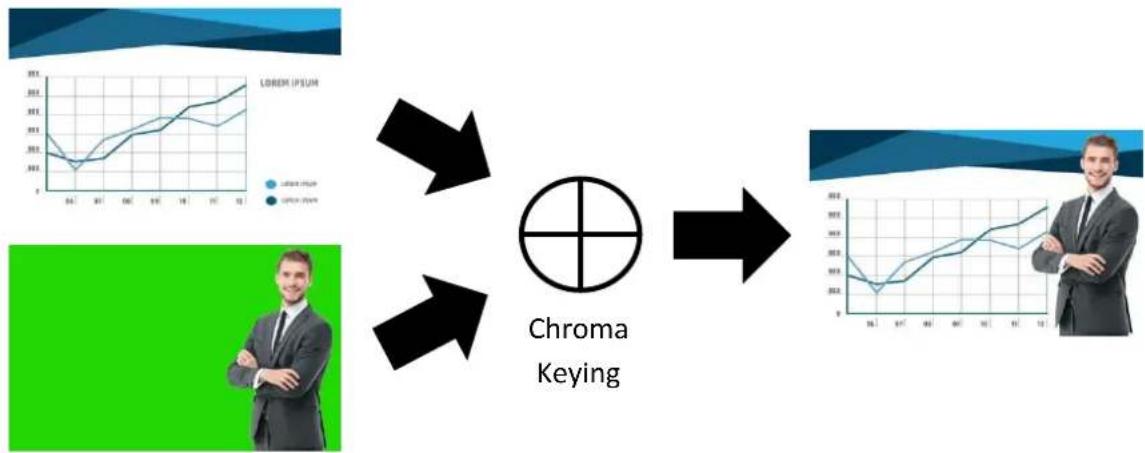
flowchart
graph TD
    A["Lower Line Graph"] --> C["Chroma Keying"]
    B["Upper Line Graph"] --> C
    C --> D["Chroma Keying"]
    style A fill:#f9f,stroke:#333
    style B fill:#bbf,stroke:#333
    style C fill:#fff,stroke:#333
    style D fill:#dfd,stroke:#333
6.4 Displaying a variety of Sources at the same time
The Flex™ output allows the user to show a variety of sources at the same time and these sources can then be fed as one combined image to the HS-3200 Program or Preview outputs.
The Flex™ output could be as simple as one background image and four smaller source images to make a basic Flex™ layout.
Alternatively it could be a lot more complex with a fifth image source making a fifth PIP window. You also have the ability to place a user defined color border around all PIP windows. You can re-size, crop, rotate and position the PIP windows in almost any manner that you wish. With the HS-3200, you will be allowed to enable up to eight PIP windows on the Flex™ output.
To configure the Flex™ settings, simply follow the steps outline below.
Basic Flex™ Output (Four PIP Windows)
- Enable Flex™ output on PGM or PVW window (press SHIFT and while holding down the SHIFT button, press the FLEX button). This will display the Flex™ output layout on either the PVW or PGM screen so that you will be able to configure the Flex™ output windows while viewing the changes.
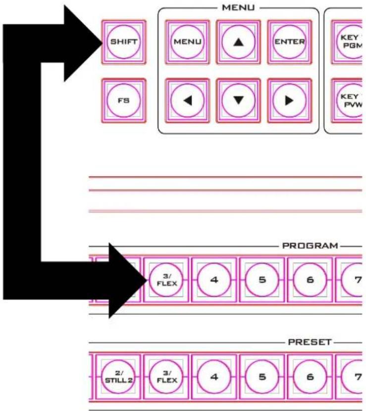
flowchart
graph TD
    A["SHIFT"] --> B["MENU"]
    B --> C["ENTER"]
    C --> D["KEY PGM"]
    E["FS"] --> F["◀"]
    F --> G["▼"]
    G --> H["▶"]
    I["PROGRAM"] --> J["3/ FLEX"]
    J --> K["4"]
    K --> L["5"]
    L --> M["6"]
    M --> N["7"]
    O["PRESSET"] --> P["2/ STILL 2"]
    P --> Q["3/ FLEX"]
    Q --> R["4"]
    R --> S["5"]
    S --> T["6"]
    T --> U["7"]
- Press the MENU button on the switcher's control panel to open the OSD menu on the Multiview screen and select Flex Src sub menu. On the sub menu that opens, select any of the presets to enable the desired preconfigured layout on the screen.
| Flex Src | Flex Src | Flex Src 1 | ||
| Flex Src Bgnd | Black | |||
| P-in-P 1 Src | Black | Enable On | ||
| P-in-P 2 Src | Black | Enable On | ||
| P-in-P 3 Src | Black | Enable On | ||
| P-in-P 4 Src | Black | Enable On | ||
| Keyer 1 | Input 1 | Input 2 | Enable On | |
| Flex Preset | Preset 1 | Preset 2 | Preset 3 | |
| Preset 4 | Preset 5 | Preset 6 |
- The Flex™ output consists of one background image and four smaller source images overlapped on the background image in four separate individual PIP windows. The options above the Keyer row allow you to select a source for the background (FLEX Src Bgnd) and then assign an input source to the respective Flex™ output windows (P-in-P 1 Src to P-in-P 4 Src).
| Flex Src | Flex Src | Flex Src 1 | ||
| Flex Src Bgnd | Input 4 | |||
| P-in-P 1 Src | Input 6 | Enable On | ||
| P-in-P 2 Src | Input 7 | Enable On | ||
| P-in-P 3 Src | Input 11 | Enable On | ||
| P-in-P 4 Src | Input 12 | Enable On | ||
| Keyer 1 | Input 1 | Input 2 | Enable On | |
| Flex Preset | Preset 1 | Preset 2 | Preset 3 | |
| Preset 4 | Preset 5 | Preset 6 |
- In order to configure the corresponding FLEX window's size, position, border style, border color, border width and the crop settings, open the P-in-P sub menu and in the Keyer option, you will be able to find options Flex PinP 1 to 4. Select one of them and adjust the Flex™ P-in-P windows accordingly.
| P-in-P | Keyer | Flex PinP 1 | Fine | Normal | |||
| Position | X | 20% | Y | 10% | Size | 40% | |
| Border | Normal | ||||||
| Luma | 100% | Sat | 80% | Hue | 0 | ||
| Width | 2% | Soft | 0% | Opac | 100% | ||
| Shade Matte | Luma | 100% | Sat | 80% | Hue | 60 | |
| Shade Soft | 2% | Shade Pos | 50 | Direction | 35 | ||
| Crop | Left | 0% | Right | 0% | Size | 0% | |
| Top | 0% | Bot | 0% | Soft | 0% | ||
- Once configured, save the Flex™ settings in User Memories for easy access.
After the Flex™ settings are successfully configured, as depicted in the diagram below, each FLEX window will display the respective source images. Use the Flex™ feature in different scenarios and apply the proper keying effect accordingly.
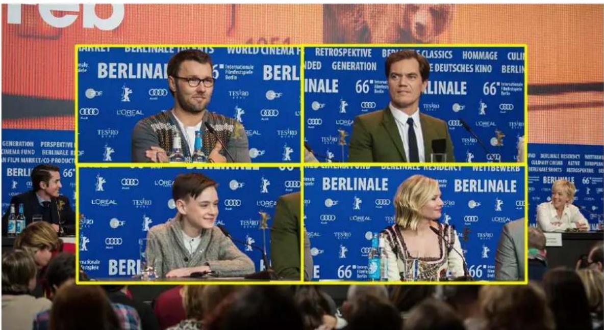
Flex™ and Downstream Key: Talk Show and Interview TV Show
Flex™ and Chroma Key: Educational Program
Flex™, Chroma Key, Luma Key and PIP: Cultural Program or Live Sports Program

Assigning a video source to a PIP window using shortcut keys
In addition to assigning a video source to a Flex™ output window using the OSD MENU, the user can also use shortcut keys to easily switch between different Flex™ output window sources. Press and hold KEY 1-4 PVW buttons, and the program row will be backlit red. Press the program row buttons to change the Flex™ output window content.
Simultaneously Enabling up to Eight PIP Windows
The HS-3200 allows you to enable up to eight PIP windows at the same time. This can be achieved by enabling the Flex™ output along with the four keyers built into the HS-3200. Before using this feature, the four keyers must be set to PIP mode and the four FLEX windows must be adjusted and positioned accordingly. The steps outlined below will guide you in configuring the eight PIP windows.
- Enable Flex™ output on PGM or PVW window (press SHIFT and while holding down the SHIFT button, press the FLEX button). This will display the Flex™ output layout on either the PVW or PGM screen so that you will be able to configure the Flex™ output windows while viewing the changes.
- Pre-configure the four Flex™ output windows in the P-in-P sub menu by adjusting the size and position of the corresponding windows. Remember to modify the luma key parameters accordingly. Note that you can change the Flex™ output window content in the Flex Src sub menu.
| P-in-P | Keyer | Flex PinP 1 | Fine | Normal | |||
| Position | X | 20% | Y | 10% | Size | 40% | |
| Border | Normal | ||||||
| Luma | 100% | Sat | 80% | Hue | 0 | ||
| Width | 2% | Soft | 0% | Opac | 100% | ||
| Shade Matte | Luma 100% | Sat 80% | Hue 60 | ||||
| Shade Soft 2% | Shade Pos 50 | Direction 35 | |||||
| Crop | Left 0% | Right 0% | Size 0% | ||||
| Top 0% | Bot 0% | Soft 0% | |||||
- Open the Keyer sub menu, set Keyers 1 – 4 to PIP mode and enable Luma Key.
| Keyer | Keyer | Key 1 | Normal | ||||
| Keyer Ctrl | Luma | P-in-P | Opac | 100% | |||
| Lift | 0% | Gain | 1.0 | Invert | Off | ||
| Key Source | Input 1 | Fill | Black | ||||
| Mask | Left | 0% | Right | 0% | |||
| Top | 0% | Bot | 0% | ||||
- Adjust the P-in-P windows in the P-in-P sub menu.
| P-in-P | Keyer | Key 1 | Fine | Normal | |||
| Position | X | 20% | Y | 10% | Size | 40% | |
| Border | Normal | ||||||
| Luma | 100% | Sat | 80% | Hue | 0 | ||
| Width | 2% | Soft | 0% | Opac | 100% | ||
| Shade Matte | Luma | 100% | Sat | 80% | Hue | 60 | |
| Shade Soft | 2% | Shade Pos | 50 | Direction | 35 | ||
| Crop | Left | 0% | Right | 0% | Size | 0% | |
| Top | 0% | Bot | 0% | Soft | 0% | ||
- After the Flex™ output and the four PIP windows are successfully configured, enable the Flex™ output by pressing the Flex™ button while holding down the SHIFT button, and then press KEY1 PGM to KEY4 PGM buttons to activate the four PIP windows on the Program Output. The diagrams below provide an example of an eight PIP window display.
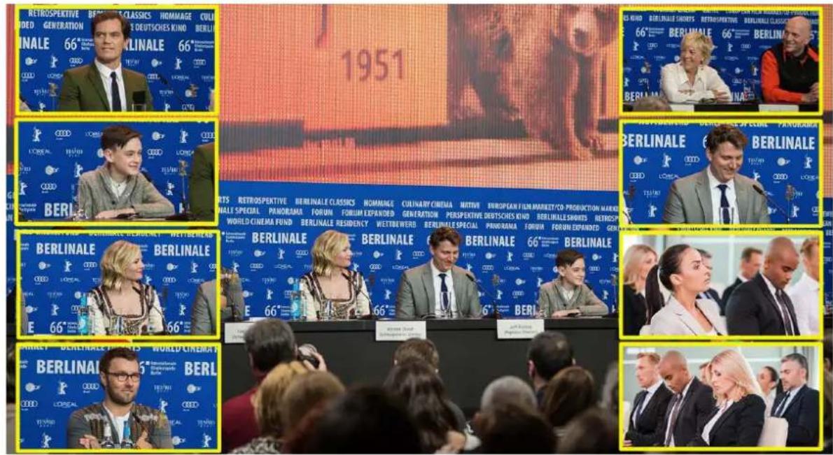
6.5 Shortcut Keys to assigning Output Sources
In general, the HS-3200 offers 9 output ports (SDI 1 - 6 / HDMI 1-3) and all 9 ports can be configured to output one of the following:
- Flex Src 1/2
- Still 2
- Still 1
- Input 1 - 12
• CLN PVW (Clean PVW)
• CLN PGM (Clean PGM) - PG + DSK
• PVW - PGM
• MultiV2 (Multi view 2) - MultiV (Multi view)
In addition to setting the source of these 9 output ports in OSD menu → Outputs → Output, you can also use the shortcut keys on the control panel to assign the output sources. The instructions are outlined as follows:
- The diagram below depicts the corresponding buttons for selecting the respective output ports as well as the video sources. The program row on the top allows you to first select the output port and the preset row below allows you to then assign a video source to the selected output port.
Note: Pressing the BLK/MATTE button switches between two different groups of video sources.
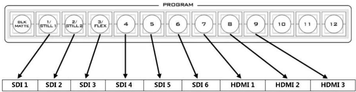
flowchart
graph TD
    A["BLK MATTE"] --> B["1/ STILL 1"]
    B --> C["2/ STILL 2"]
    C --> D["3/ FLEX"]
    D --> E["4"]
    E --> F["5"]
    F --> G["6"]
    G --> H["7"]
    H --> I["8"]
    I --> J["9"]
    J --> K["10"]
    K --> L["11"]
    L --> M["12"]
    N["SDI 1"] --> O["SDI 2"]
    O --> P["SDI 3"]
    P --> Q["SDI 4"]
    Q --> R["SDI 5"]
    R --> S["SDI 6"]
    S --> T["HDMI 1"]
    T --> U["HDMI 2"]
    U --> V["HDMI 3"]
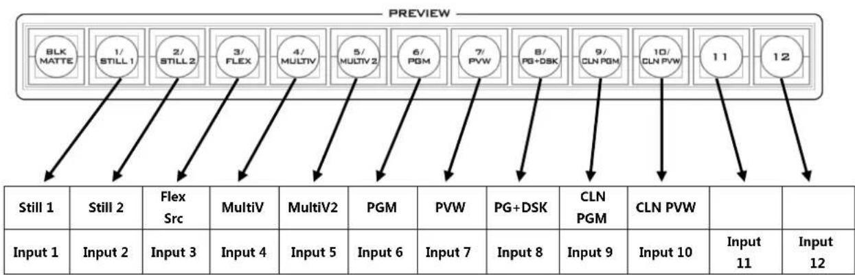
flowchart
graph TD
    A["BLK MATTE"] --> B["1/ STILL 1"]
    B --> C["2/ STILL 2"]
    C --> D["3/ FLEX"]
    D --> E["4/ MULTIV"]
    E --> F["5/ MULTIV 2"]
    F --> G["6/ PGM"]
    G --> H["7/ PVW"]
    H --> I["8/ PG+DSK"]
    I --> J["9/ CLN PGM"]
    J --> K["10/ CLN PVW"]
    K --> L["11"]
    L --> M["12"]

    N["Still 1"] --> O["Input 1"]
    O --> P["Input 2"]
    P --> Q["Input 3"]
    Q --> R["Input 4"]
    R --> S["Input 5"]
    S --> T["Input 6"]
    T --> U["Input 7"]
    U --> V["Input 8"]
    V --> W["Input 9"]
    W --> X["Input 10"]
    X --> Y["Input 11"]
    Y --> Z["Input 12"]

    style A fill:#f9f,stroke:#333
    style B fill:#f9f,stroke:#333
    style C fill:#f9f,stroke:#333
    style D fill:#f9f,stroke:#333
    style E fill:#f9f,stroke:#333
    style F fill:#f9f,stroke:#333
    style G fill:#f9f,stroke:#333
    style H fill:#f9f,stroke:#333
    style I fill:#f9f,stroke:#333
    style J fill:#f9f,stroke:#333
    style K fill:#f9f,stroke:#333
    style L fill:#f9f,stroke:#333
    style M fill:#f9f,stroke:#333
-
Upon pressing the FS/AUX button, you will see the following button LED behavior:
-
Buttons 1 – 9 on the program row turn solid red except for Button 1 which should be flashing by default.
-
Buttons BLK/MATTE – 10 on the preset row should turn solid blue except for one flashing button that is the video source assigned to the output port selected on the program row.
-
Press one of buttons 1 – 9 on the program row to select an output port. The selected button should turn flashing red.
- Press one of buttons 1 – 10 on the preset row to select a video source; the corresponding video sources are listed as follows:
1: Still 1
2: Still 2
3 : Flex Src
4:MultiV
5 : MultiV2
6 : PGM
7: PVW
8 : PG+DSK
9 : CLN PGM
10 : CLN PVW
Once selected, the button should turn flashing blue.
- To select input 1 – 12 video sources, you will need to press the BLK/MATTE button to switch to another group of video sources. All buttons on the preset row should turn solid green. Press the corresponding button to select the video source and the selected button should turn flashing green, indicating that the assignment is successful. Button 1 corresponds to input 1, button 2 corresponds to input 2 and etc.
- Press the FS/AUX button to deactivate the shortcut keys.
Chapter 7 Video Streaming and Recording
The HS-3200 Portable Video Studio includes a built-in Video Streaming Server (NVS-31) allowing the user to stream and record your program at the same time. From any SDI/HDMI input sources, the Datavideo's video streaming server generates an H.264 encoded stream that is compliant with RTSP or RTMP(S) protocols. While encoding the video at bit rates appropriate for live streaming, the Datavideo NVS-31 concurrently records a high-quality MP4 file to an SD card.
Note: The built-in video streaming server and recording device are referred to as NVS-31.
7.1 Streaming Network Connection and Device Search
This section details how to connect the NVS-31 to a network with or without a DHCP server, and describes how to acquire the NVS-31's IP address.
Connecting to a DHCP Network (DHCP Mode)
Follow the following procedure to scan your DHCP network for connected NVS-31 devices.
Note: The NVS-31 will be automatically assigned an IP address upon connection to the DHCP network.
-
Connect the NVS-31's stream port to the network via an Ethernet cable.
-
Turn on the HS-3200's power and the NVS-31 will also be turned ON in the DHCP mode by default.
-
Connect the laptop to the same network that the NVS-31 is connected to and download the free IP Finder utility program.
-
Double click the IP Finder utility program icon to open the IP Finder interface.
-
Click the SCAN button to start searching for connected devices.

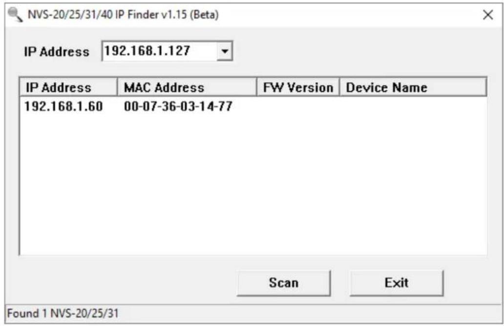
Connecting to a NON-DHCP Network (Static IP)
Upon connection to a non-DHCP network, the NVS-31 will not be assigned of any IP addresses. As such it is recommended that you manually assign a fixed IP address to the device or use the default IP address (192.168.1.60).
Default Fixed IP
Default Fixed IP is primarily used in point-to-point connection, such as connecting the PC to the NVS-31 directly. In a non-DHCP environment, the NVS-31 works in fixed IP mode only.
To configure the NVS-31 to the default IP, please follow the steps outlined below:
-
Connect the NVS-31's stream port to the network via an Ethernet cable.
-
Turn on the HS-3200's power and the NVS-31 will also be turned ON in the DHCP mode by default.
-
Search for the NVS-31 device according to the method as detailed in the previous DHCP section. Once found, log into the user interface on the web browser.
-
Enter the system page by clicking the "System" tab on the home of the user interface.
-
In the "Network Setting", disable the DHCP mode.
-
You will then be allowed to manually enter the static IP address once the DHCP mode is disabled. The static IP is 192.168.1.60 by default. The subnet mask and default gateway are 255.255.255.0 and 192.168.1.254 respectively.
Tip: If you forget or lose the IP address, do the following to reset the network settings.
- Turn off the switcher.
- Press the RECORD and STREAM buttons at the same time then turn ON the power of the switcher
- Wait for about five seconds and release the button push as soon as you see the RECORD and STREAM button LEDs light up.
- The IP address should be the default IP which is 192.168.1.30.
Troubleshooting the Network Connection
Connect the NVS-31 to the network and open the IP Finder utility program. Scan for the device. If not found, it is possible that your network is not assigning IP addresses. Reasons of this are outlined as follows:
- Router or DHCP server is not connected to the network.
- New devices are blocked by the network administrator.
- Anti-virus software or the firewall blocks the communication.
Solve the problem by trying the following:
- Turn off the router, wait for 10 seconds then turn on the router again.
- Reset the NVS-31 to the factory default:
- Turn off the switcher.
- Push the Record and Stream buttons simultaneously while turning on the switcher's power.
- Wait for about five seconds and release the button push as soon as you see the RECORD and STREAM button LEDs light up.
- Reboot the PC.
If the problem still persists, try the following ways:
- Temporarily shut down the anti-virus software or firewall.
- Make sure no other devices are connected to the LAN (wired or wireless) because this may result in IP conflicts.
After trying all methods and if the problem is still not solved, the NVS-31 video streaming server offers the fixed IP feature that allows you to establish direct connection to the NVS-31. The default IP address is 192.168.1.60.
This method allows you to configure the NVS device to the IP range of your network so that you do not need a DHCP server to gain access to the NVS device.
- Connect your PC to the NVS device directly using an Ethernet cable (not necessarily a crossover cable).
Next, change the network settings of your PC or laptop.
- Click START located at the bottom left corner of your screen.
- On the text bar, enter Network Connections then click the icon that appears.
- Double click the network adapter that connects your PC or laptop to the network.
- Click the "Properties" button.
- Select "Internet Protocol Version 4 (TCP/IPv4)" option and click the "Properties" button.
- Check the "Obtain an IP address automatically" option.
- Enter IPv4 settings:
- IP Address: 192.168.1.2
- Subnet Mask: 255.255.255.0 (System default is 255.255.255.0)
- Default Gateway: Not required for one-to-one connection.
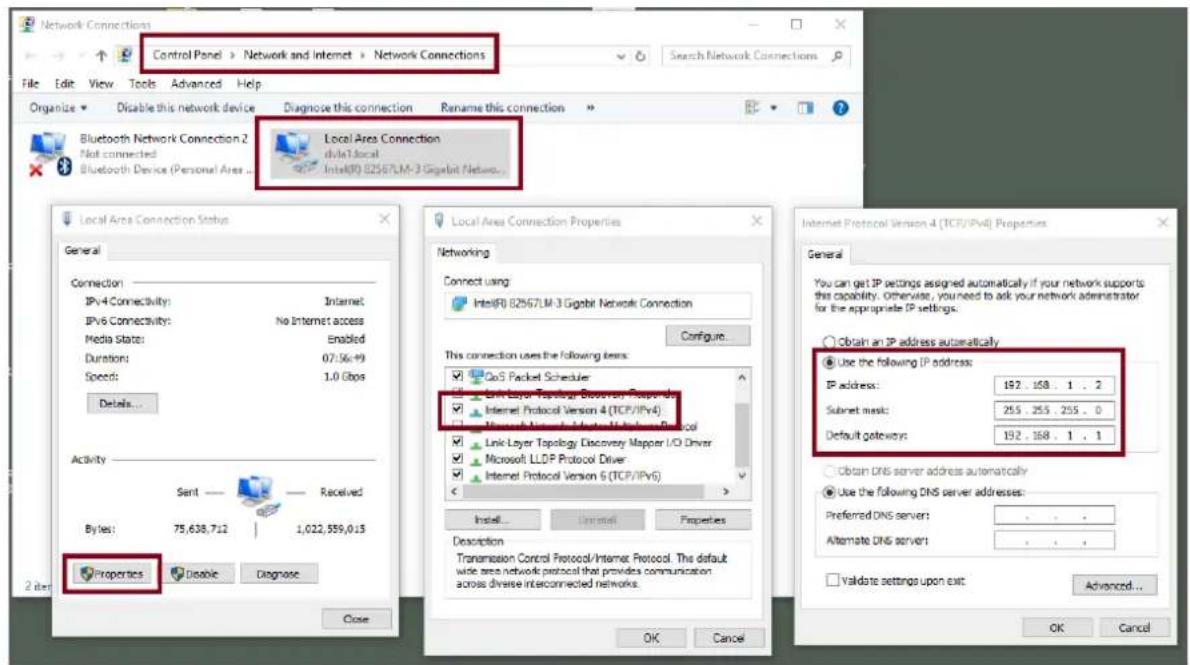
Note: Please write down the IPv4 address previously entered as it may be needed after you are done with streaming or recording.
• The NVS-31 should now be connected with an IP address of 192.168.1.60.
If the NVS-31 still cannot connect, simply restore the NVS-31 to the factory defaults.
- Turn off the switcher.
- Push the Record and Stream buttons simultaneously while turning on the switcher's power.
- Wait for about five seconds and release the button push as soon as you see the RECORD and STREAM button LEDs light up.
- Make sure no other devices are connected to the LAN (wired or wireless) because this may result in IP conflicts.
- Login the NVS-31 via a web browser.
- Default user name is admin
- Default password is 000000
- Click the "System" tab then on the system page, enter network settings such as static IP and default gateway. Make sure that the default gateway matches your connected network and no device shares the same IP as the NVS-31.
For example, if your router's default gateway IP is 10.10.1.1, then in the default gateway field, you should also enter 10.10.1.1. Then set the IP address of the NVS-31 to 10.10.1.X, which can range from 10.10.1.2 to 10.10.1.255. Pick an unused IP address.
Network Setting
| DHCP | Static IP |
| Enable(DNS AUTO) | 192.168.1.60 |
| Subnet Mask | Default Gateway |
| 255.255.255.0 | 192.168.1.254 |
| Primary DNS | Secondary DNS(Alternative) |
| MAC ADDRESS | |
| 00:07:36:03:C0:20 |
- DHCP : Disable
- Static IP : X.X.X.Y ; the first three decimal numbers must be the same as your router or switch. The number Y must be a number not used by any devices connected to the network.
- Subnet Mask : 255.255.255.0
- Default Gateway : Z.Z.Z.Z ; same as the gateway IP of your router or switch.
Note: Some router may require special gateway IP setting; instead of the standard 192.168.1.1. Therefore, you should check the network properties on the PC before switching to the fixed IP mode.
For example, some routers have a gateway IP of 192.168.1.254 and as a result, the default gateway and primary DNS fields on the NVS-31 must also be configured to 192.168.1.254.
- Primary DNS: Same as the default gateway IP, which, if causing issues, can be changed to 8.8.8.8 or 8.8.8.4 (Public DNS provided by Google).
- Click the "Submit" button to save the network settings.
- Reconnect the PC and the NVS-31 to the network.
- Restore the PC's original network settings.
- Shut down the HS-3200; wait for approximately five seconds before turning the HS-3200 back ON.
- You should be able to access the NVS-31 through the fixed IP address.
Advanced Troubleshooting
If you still are unable to connect, please try the following:
- Use the ARP table to search for the encoder's MAC address; the device's MAC address is on the print label at the bottom of your HS switcher.
- MAC address starts with 00:07:36:03:xx:xx.
-
Switcher's MAC address starts with 00:07:36:07:xx:xx (HS-3200 and HS-3200 only)
-
On the command prompt (terminal on MAC OS), enter "arp -a" then press enter key to display an ARP list. See if the NVS-31 is successfully connected to the network.
- Execute services.msc, and on the right column of the "Services" window, locate "DHCP Client" then click "Restart".
- On the command prompt, enter ipconfig/flushdns followed by ipconfig/release and ipconfig/renew.
7.2 Web User Interface
By now, we have obtained the IP addresses of the PC and the NVS-31. Enter the NVS-31's IP address into the address bar of a browser then hit the ENTER button. Login by entering the user name as well as the password into a pop-up dialogue box as shown below.
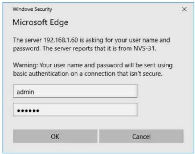
Username: admin
Password: 000000
Click OK to login. Once logged in, the first page that appears will be the Status page.
Status
You will see the Status page immediately after logging into the NVS-31 web UI. On the Status page, you will be able to view the Operation Mode, Video Resolution, Stream Settings (RTSP/RTMP(S)/HLS/SRT/TS), Record Settings, Record Media and Messages.
![1 CHANNEL STREAMING ENCODER / RECORDER NVS-31 Status Operation Mode Storage CG System Operation Mode : Record and Stream Video Resolution : 1920x1080p, 60.00fps Stream Settings : Same as Input, 30fps, 2000kb/s, audio 128kb/s, RTSP RTSP : rtsp://192.168.1.60:554/live2 or rtsp://192.168.1.60:8000/live2 RTMP : TS : udp://@239.100.100.101:12345 Record Settings : Same as Input, 30fps, 3000kb/s, audio 128kb/s Record Media : SD Card, EXFAT, 14.56GB [free space] / 14.00GB [total space] Messages :](/content/2026/05/950367/images/ffeaaa7aea656dfc2fd6af6c4e4bc79f8eaa94fd7ec0ac5c28e823bcec3714ba.jpg)
Note: The NVS-31 web UI does not update automatically so to learn the latest device status, please refresh the page manually.
While monitoring streaming and recording, please update the page periodically regardless of how you operate the device (using the device's physical buttons only or using the device's physical buttons along with the web UI). This ensures the page is always displaying the most up-to-date information.
If an error occurs, the error code will be shown in the “Messages” field. The device’s error codes are listed in the table below.
| Error Messages | Descriptions | Error Code |
| STR_UP_ETH_LINK_DOWN | Ethernet Link Down | 133 |
| STR_UP_ETH_LINK_RESTORE | Ethernet Link Up from Down | 134 |
| STR_UP_ETH_CONN_ERR | RTMP Cannot Publish (Retrying) | 140 |
| STR_UP_ENC_START_ERR | Encoder Start Failed | 129 |
| STR_UP_ENC_BUFF_ERR | Encoder Buffer Error | 130 |
| STR_RUN_ETH_LINK_DOWN | Ethernet Link Down (Dropped) | 133 |
| STR_RUN_ETH_CONN_ERR | RTMP Drop Connection (Retrying) | 140 |
| STR_RUN_ENC_BUFF_ERR | Encoder Buffer Error | 130 |
| STR_RUN_PROG_BUFF_ERR | Streamer Buffer Error | 137 |
| STR_RUN_PROG_SOCKET_ERR | Streamer Socket Error | 140 |
| STR_STOP_PROG_EXIT_ERR | Streamer Stop Failed | 141 |
| REC_UP_DISK_ERR | Disk Bad Sectors/Read Only/File System Error | 148 |
| REC_UP_DISK_EMPTY | No Disk | 144 |
| REC_UP_ENC_START_ERR | Encoder Start Failed | 129 |
| REC_UP_ENC_BUFF_ERR | Encoder Buffer Error | 130 |
| REC_UP_PROG_START_ERR | Recorder Start Failed | 148 |
| REC_UP_PROG_BUFF_ERR | Recorder Buffer Error | 154 |
| REC_RUN_DISK_FULL | Disk Full | 151 |
| REC_RUN_ENC_BUFF_ERR | Encoder Buffer Error | 130 |
| REC_RUN_PROG_WRITE_ERR | Recorder Write Failed | 153 |
| REC_RUN_PROG_BUFF_ERR | Recorder Buffer Error | 137 |
| REC_STOP_DISK_EXIT_ERR | Unmount Disk Failed | 156 |
| REC_STOP_PROG_EXIT_ERR | Recorder Stop Failed | 157 |
Operation Mode
Click the Operation Mode tab on the tool bar to open the operation mode configuration page.
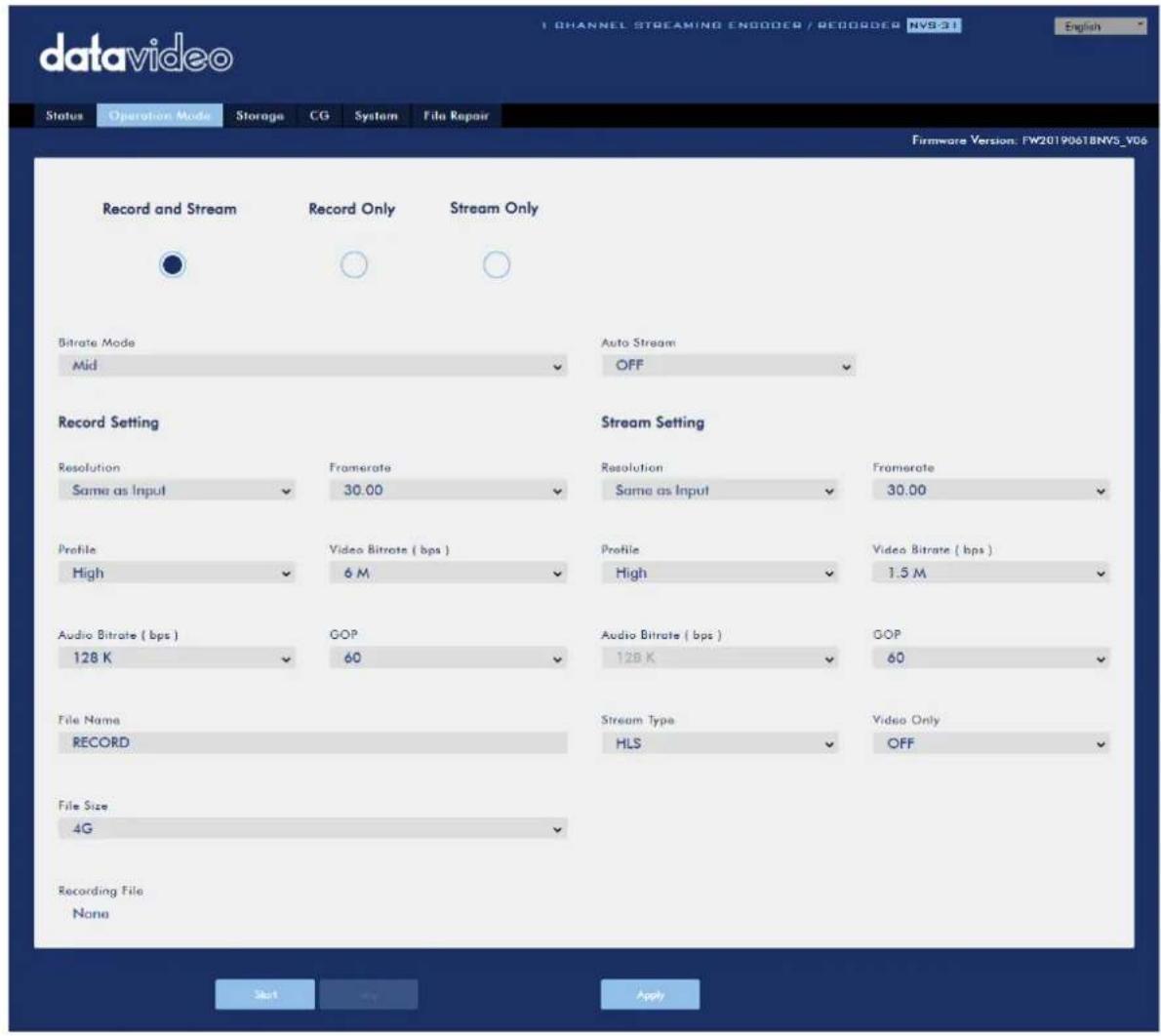
The NVS-31 offers the following operation modes:
- Record and Stream: Streaming and recording functions are enabled at the same time.
• Stream Only: Only streaming mode is enabled.
• Record Only: Only recording mode is enabled.
In each mode, the user will be allowed to customize various stream and record settings.
In the Stream Only mode, settings such as Resolution, Frame Rate, Profile, Video Bitrate (bps), Audio Bitrate (bps), GOP and Stream Type can be configured.
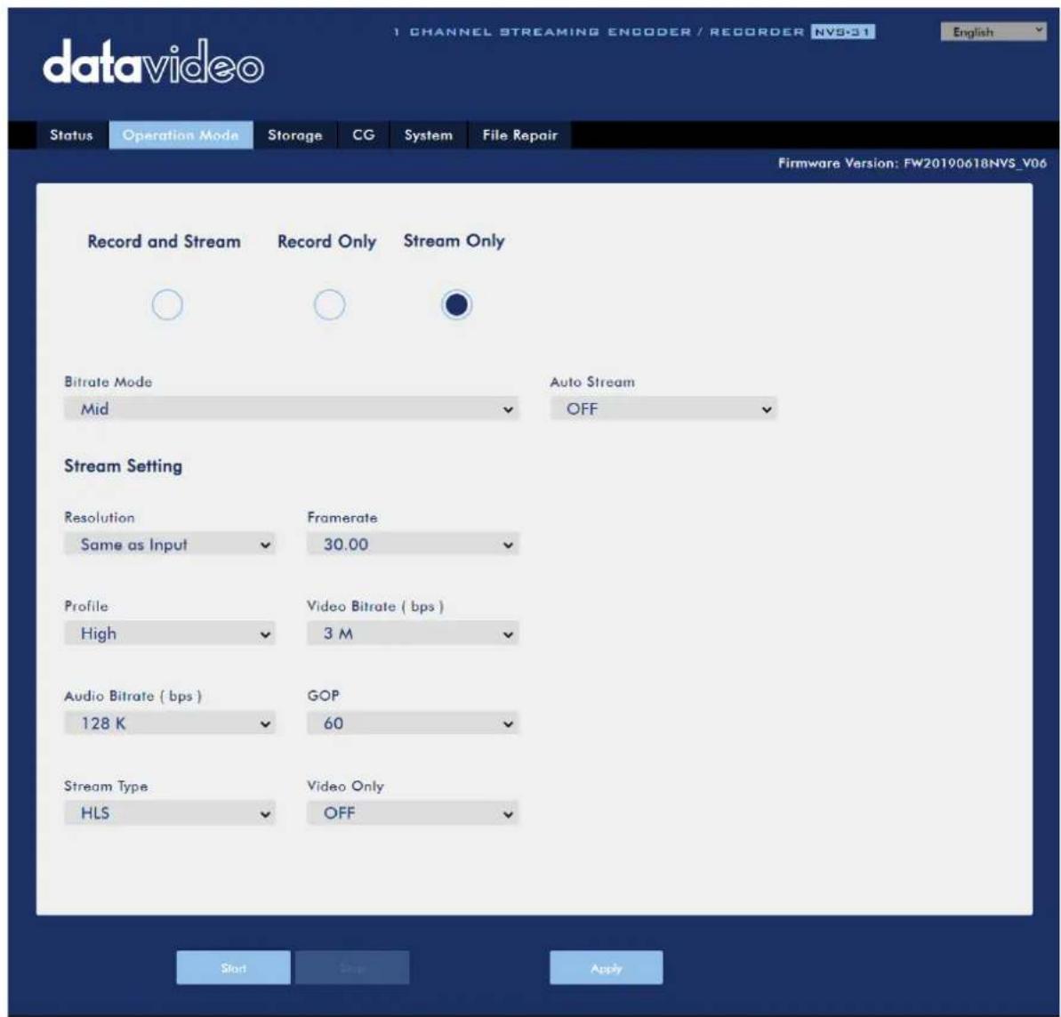
Five stream types are available on the NVS-31 and they are RTSP, RTMP(S), HLS, SRT and TS. See Section 6.3 for details.
Click the "Apply" button to apply the new stream settings. Click the "Start" button to open the stream and the "Stop" button to end the stream.

As for recording, the settings are Resolution, Frame Rate, Profile, Video Bitrate (bps), Audio Bitrate (bps), GOP, File Name and File Size.
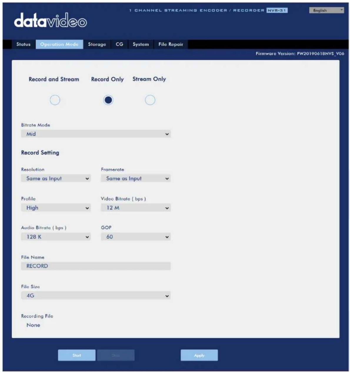
Click the "Apply" button to apply the new record settings. Click the "Start" button to start recording and the "Stop" button to stop recording.

flowchart
graph LR
    A["Start"] --> B["Stop"] --> C["Apply"]
Stream and Record Settings
In the section, you will be introduced various setting options of stream and record functions.
| Stream Encoder Settings | |
Bitrate Mode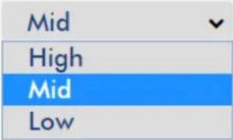 | Bitrate ModeThe bitrate mode sets the video bitrate mode for your video stream. The available modes are high, mid and low.Note: You can also switch between different bitrate modes by pressing the Bitrate button on the Record/Stream panel. See Section 7.4 for details. |
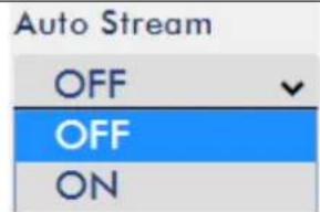 | Auto StreamIf the Auto Stream is enabled, in the event of power outage, the stream will be automatically restored after the switcher is powered ON again. |
Resolution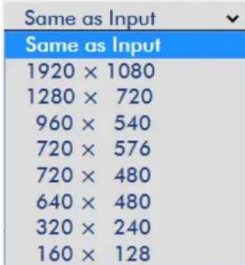 | ResolutionThe first step of encoder setup is to adjust the image size. It is best to either match your original video source or scale it down. For example, capture at HD 720 and stream at HD 720. Or capture at HD 720 and stream at 540 (high).You should never be scaling up and streaming at a higher resolution than your original video source. For example, it does not make sense to capture at 720 and stream at 1080. Note that you will also have no gain in quality and you are using more bandwidth than is necessary for your viewers.You should also be aware that higher resolutions require greater processing power to encode the stream.Attempting too high of a resolution on too little processing power can result in degraded image quality and corrupted or interrupted streams or recordings. |
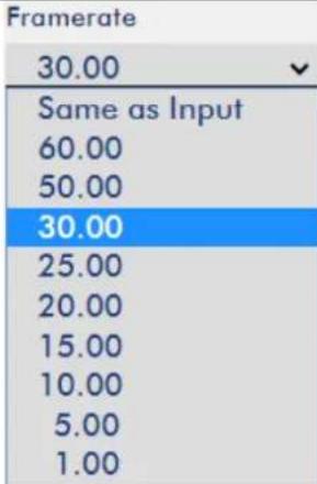 | Frame RateSelect a frame rate from the drop-down menu for video streaming. Note that frame rates should always match the frame rate of the video source. |
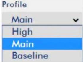 | ProfileProfile sets the H.264 encoding profile for your stream. The available options areBaseline, Main, andHigh. Typically, Highprofile provides the best image quality and is suitable in most instances. However, depending on the decoder used when viewing the stream, such as with mobiles devices, a Main or Baseline profile may be required. |
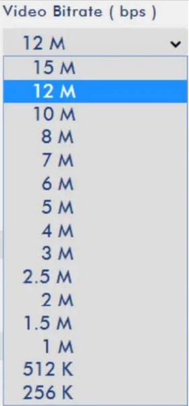 | Video Bitrate (bps)The bitrate of the video specifies the amount of information stored in the video. The higher the bitrate is, the clearer the video is. However, when choosing your encoding settings for streaming, you should first check your available upload bandwidth. A good rule of thumb is for the bitrate of your stream to use no more than 50% of your available upload bandwidth capacity on aDEDICATEDline. For example, if the result you get from a speed test shows that you have 2Mbps of upload speed available, your combined audio and video bitrate should not exceed 1Mbps.Usually high bitrate means good image quality; however, there are also exceptions. For example, SD video may appear acceptable at 1000 Kbps (1M) but HD video is unacceptable at 1000 Kbps. Therefore we recommend the following settings for your video bitrate:When NVS-31 is in record-only mode, the recommended video bitrate is 16 Mbps.When NVS-31 is in stream-only mode, the recommended video bitrate is 10 Mbps.When NVS-31 streams and records simultaneously, sum of the stream and record video bitrates should not exceed 12Mbps. |
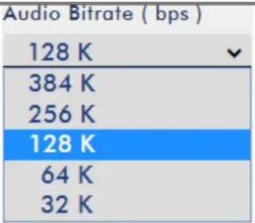 | Audio Bitrate (bps)The NVS-31 offers the user the following audio bitrates at which you may want to stream the audio. It is recommended to select 128Kbps or higher. |
| GOP60180160140120100605030252015105321 | GOPGOP pattern with longer GOP length encodes video very efficiently. Shorter GOP lengths usually work better with video that has quick movements, but they do not compress the data rate as much. Depending on your applications, the NVS-31 offers the user 16 GOP sizes ranging from 1 to 180. |
| Stream Settings | |
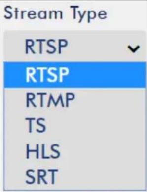 | Stream TypeThe NVS-31 offers the user six stream types. There are RTSP, RTMP(S), TS, HLS, SRT and Youtube.Please note that when streaming, the NVS-31 converts video into data, which are sent across an IP network. High bitrates consume more bandwidth across the IP network. In a gigabit office LAN, high bitrate may not be a concern and Speed/Bandwidth is therefore not a limitation in an NVS-31 application environment.If your available bandwidth is limited, you should reduce both your resolution and your bitrate accordingly. A good rule of thumb is for the bitrate of your stream to use no more than 50% of your available upload bandwidth capacity on a dedicated line. For example, if the result you get from a speed test shows that you have 2Mbps of upload speed available, your combined audio and video bitrate should not exceed 1Mbps. |
| Stream Type - RTSP | |
| RTSP Port554 | RTSP PortRTSP Port is 554 by default. |
 | RTSP HTTP PortRTSP HTTP port is 8000 by default. | |
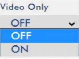 | Video OnlyEnable this option if you just want to stream the video without the audio. | |
RTSP Username/PasswordThe account and password are root by default.RTSP Account   | ||
| Stream Type - RTMP(S) | ||
| RTMP URL | RTMP URLEnter the RTMP URL obtained from any live streaming platform such as Ustream.Note: The NVS-31 supports RTMP(S) Publish only and not RTMP(S) Local. | |
| RTMP URL | Stream NameEnter the stream name or key from any live streaming platform such as Ustream. | |
| Account | AccountEnter your RTMP account name. | |
| Password | PasswordEnter the password of your RTMP account. | |
| Audio OnlyOFFOFFVideo OnlyAudio Only | Audio OnlyIn this option, the user is allowed to choose to stream Audio Only or Video Only. If disabled, video and audio streams will be delivered simultaneously. | |
| Stream Type - TS | ||
| TS Port12345 | TS PortThe TS port number is 12345 by default. | |
Stream Type - RTMP(S)
| RTMP URL | RTMP URLEnter the RTMP URL obtained from any live streaming platform such as Ustream.Note: The NVS-31 supports RTMP(S) Publish only and not RTMP(S) Local. | |
| RTMP URL | Stream NameEnter the stream name or key from any live streaming platform such as Ustream. | |
| Account | AccountEnter your RTMP account name. | |
| Password | PasswordEnter the password of your RTMP account. | |
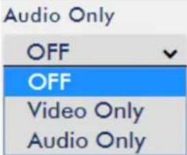 | Audio OnlyIn this option, the user is allowed to choose to stream Audio Only or Video Only. If disabled, video and audio streams will be delivered simultaneously. | |
| Stream Type - TS | ||
| TS Port12345 | TS PortThe TS port number is 12345 by default. | |
| TS IP239.100.100.100 | TS IPThe TS IP address is 239.100.100.101 by default. | |
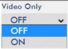 | Video OnlyEnable this option if you just want to stream the video without the audio. | |
| Stream Type – SRT | ||
| SRT Port9001 | SRT PortThe SRT port is 9001 by default. | |
| Play URLsrt://192.168.1.60:9001 | Play URLA stream URL will be generated after the Start button is clicked. | |
| Record Encoder Settings | ||
| Bitrate ModeMidHighMidLow | Bitrate ModeThe bitrate mode sets the video bitrate mode for your video stream. The available modes are high, mid and low.Note: You can also switch between different bitrate modes by pressing the Bitrate button on the Record/Stream panel. See Section 7.4 for details. | |
| ResolutionSame as InputSame as Input1920 × 10801280 × 720960 × 540720 × 576720 × 480640 × 480320 × 240160 × 128 | ResolutionRecording resolution is the number of pixels (dots) used to create an image. Higher resolutions use more pixels to create an image. This means that greater amounts of detail can be expressed in the image, but larger files sizes and a greater amount of storage (i.e. hard drive space) are required to save the images or video. | |
| Framerate30.00Same as Input60.0050.0030.0025.0020.0015.0010.005.001.00 | Frame RateFrame rate greatly impacts the style and viewing experience of a video. Different frame rates yield different viewing experiences, and choosing a frame rate often means choosing between things such as how realistic you want your video to look, or whether or not you plan to use techniques such as slow motion or motion blur effects.Below is a list of common options for different applications:24fps- This is the standard for movies and TV shows, and it was determined to be the minimum speed needed to capture video while still maintaining realistic motion.30fps- Videos with a lot of motion, such as sports, will often benefit from the extra frames per second.60+fps- Anything higher than 30fps is mainly used to create slow motion video or to record video game footage. | |
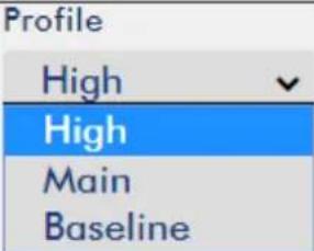 | ProfileProfile sets the H.264 encoding profile for your recorder. The available options are Baseline, Main, and High. Typically,Highprofile provides the best image quality and is suitable in most instances. | |
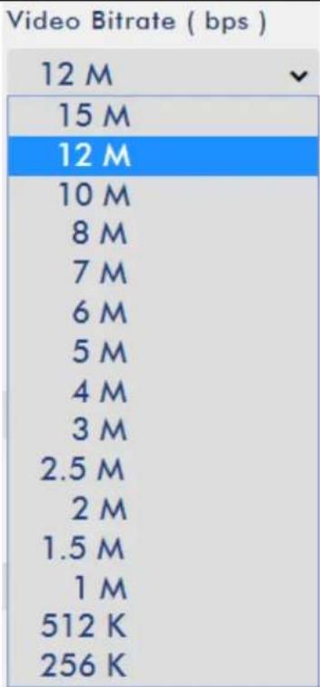 | Video Bitrate (bps)The bitrate of the video specifies the amount of information stored in the video. The higher the bitrate is, the clearer the video is.Recommended video bitrate720P or lower - 8 - 10 mbps1080P or higher - 15 mbps or higher | |
| Audio Bitrate (bps)128 K384 K256 K128 K64 K32 K | Audio Bitrate (bps)The NVS-31 offers the user the following audio bitrates at which you may want to record the audio. It is recommended to record at 128Kbps or higher. | |
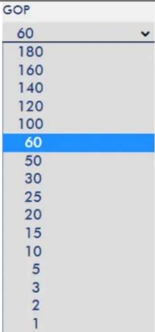 | GOPGOP pattern with longer GOP length encodes video very efficiently. Shorter GOP lengths usually work better with video that has quick movements, but they do not compress the data rate as much. Depending on your applications, the NVS-31 offers the user 16 GOP sizes ranging from 1 to 180. | |
| Record Settings | ||
| File NameRECORD | File NameEnter the name of the recording file. | |
| File Size4G200M500M1G2G4G | File SizeSelect the file size of a single recording file. | |
| Recording FileNone | Recording FileDisplay the file that is currently being recorded. | |
Note: The record function is activated after the Start button is clicked. The REC indicator will appear as shown on the left. Flashing indicates that the record function is starting. A solid color indicator means the record function has been activated successfully (The indicator flashing three
times then turned off indicates errors). The activation time is approximately 2 to 3 seconds.
Storage
The web UI of the HS-3200's built-in video streaming server (NVS-31) also displays storage device information, allowing the user to view the SD card status. The Status page of the web UI is shown in the diagram below.
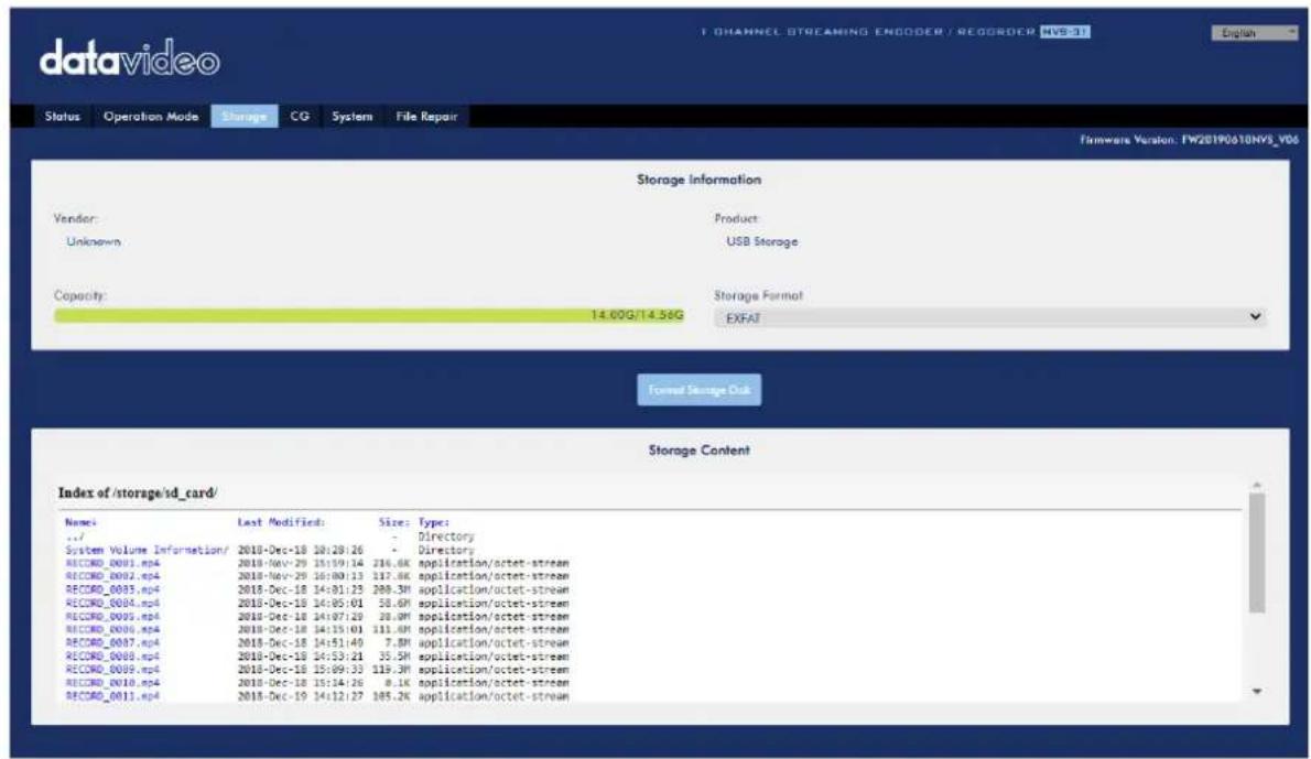
| Storage Device Information | |
| Vendor:Unknown | VendorDisplay of the manufacturer's information.Note that you should only use Class 10 SD card or above. SeeAppendix 3Recommended SD Cardsfor a list of SD cards recommended by Datavideo. |
| Product:USB Storage | ProductDisplay of the name of the SD card. |
Capacity:14.00G/14.56G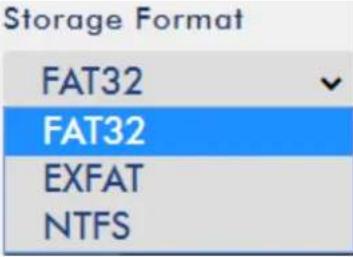 | CapacityDisplay of the SD card's total capacity and the remaining capacity.Storage FormatSelect a storage format before clickingFormat Storage Disk to format your SD card.FAT32EXFATNTFS |
 | Storage ContentDisplay of the SD card content.File nameLast ModifiedSizeType |
CG
The CG function on the HS-3200's built-in video streaming server allows the user to place a textual layer on top of the video. The CG settings on the CG page are shown in the diagram below.
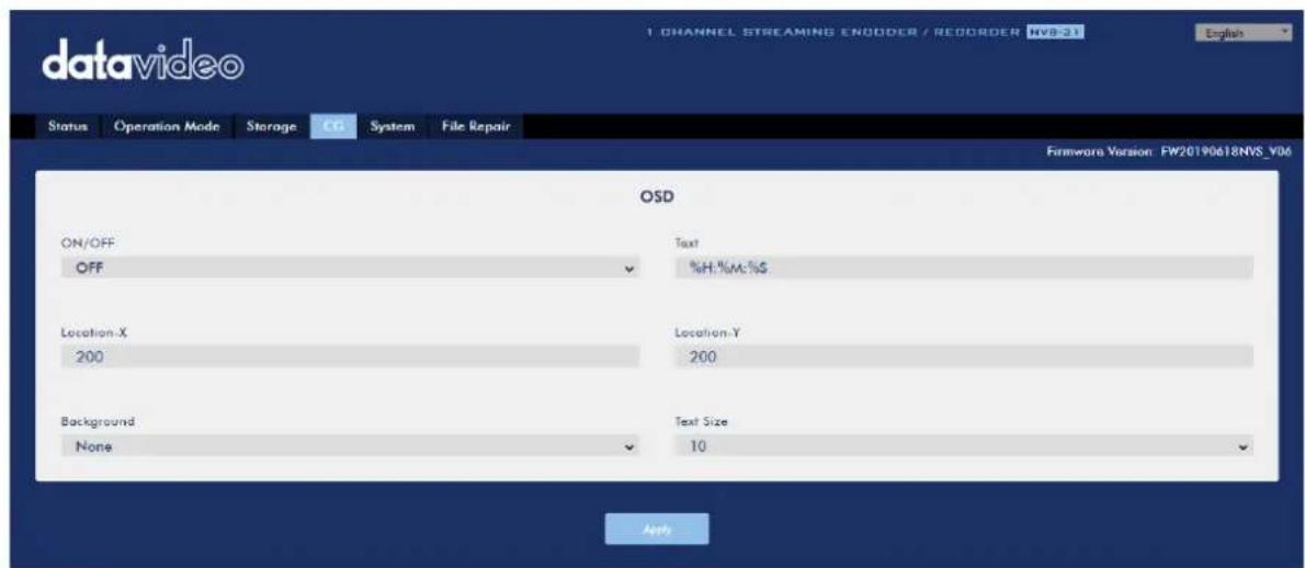
| CG Settings | |
| ON/OFFOFFOFFON | CG Enable/DisableSelect ON/OFF from this drop-down menu to enable/disable the CG overlay function. |
| Text%H:%M:%S | TextEnter the text of the CG overlay. |
| Location-X200 | Location-XEnter the x-coordinate. |
| Location-Y200 | Location-YEnter the y-coordinate. |
| BackgroundNoneNoneBlack | BackgroundYou can either select a black background or none. |
| Text Size10891011121314151617181920 | Text SizeSelect the font size of your CG overlay text. |
System
The system page of the HS-3200's built-in video streaming server allows the user to configure several network and system related settings such as DHCP enable/disable, static IP address, subnet mask, default gateway, primary and secondary DNS, and etc.
The system settings are HLS preview enable/disable, time settings, firmware update, device name, and account login information.
The system page is shown in the diagram below.

| Network Settings | |
| DHCPEnable(DNS AUTO)Enable(DNS AUTO)EnableDisable | DHCP IP AssignmentSelect an option from this drop-down menu:Enable (DNS AUTO)EnableDisable |
| Static IP192.168.1.60 | Static IP AddressThe static IP field will be activated for the user to manually enter an IP address once the DHCP is disabled. The static IP is 192.168.1.60 by default.Tip: If you do not know the device's IP address, you can always use the following method to reset the network settings.Shut down the machineTurn on the machine while holding down RECORD and STREAM buttons simultaneously.Approximately after 5 seconds, release the RECORD and STREAM buttons as soon as the button LEDs are turned ON.Fixed IP address is 192.168.1.60 by default. |
| Subnet Mask255.255.255.0 | Subnet MaskStatic IP address mode requires subnet mask, which is 255.255.255.0 by default. |
| Default Gateway192.168.1.254 | Default GatewayStatic IP address mode requires default gateway, which is 192.168.1.254 by default. |
| Primary DNS | Primary DNS (Optional)Primary DNS is required in static IP mode only but optional. |
| Secondary DNS(Alternative) | Secondary DNS (Optional)Secondary DNS is required in static IP mode only but optional. |
| MAC ADDRESS00:07:36:03:C0:20Submit | MAC AddressDisplay of NVS-31's MAC address.Submit ButtonAfter the network settings are configured, click the Submit button to save the new settings. |
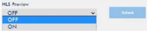 | HLS PreviewHere you will be able to enable/disable HLS preview. Click the Submit button to save the new settings. |
| Time Setting | |
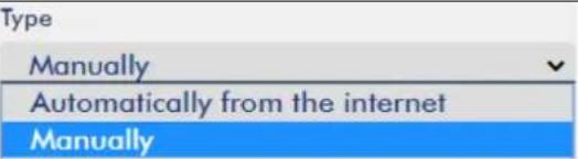 | TypeIn this drop-down menu, you can either select to allow the device to retrieve the time automatically from the Network Time Protocol (NTP) server or manually select a time zone from the Time Zone drop-down menu. |
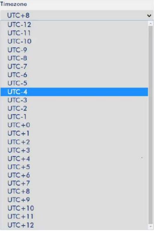 | Time ZoneClick the drop-down menu to select a time zone for your device. |
| Date2018-12-19Time15:16:38 | Date/TimeDate and Time fields show the device's system date and time values. |
Time Setting
 | You will see the calendar on the left after clicking the Date field. Simply click a day to set the date. |
 | Click theSubmitbutton to save the new settings. |
| Firmware Update | |
 | NVS-31 Firmware UpdateClick theBrowsebutton to search for the latest firmware file saved on the PC's hard disk. Click theUpdatebutton after the latest firmware file is uploaded. |
| Device Name Setting | |
 | Device Name SettingEnter a name for this device and click theSubmitbutton to write this name into the device. |
| Account Setup | |
 | Account SetupEnter the NVS-31's account name and password. Click theApplybutton to save the new settings. |
| System Control | |
 | Restore to DefaultClick this button to restore default settings.System RebootClick this button to reboot the NVS-31. |
Firmware Update
Device Name Setting
Account Setup
System Control
File Repair
The system may crash while the recording is in progress. If this happens, your record file may be damaged. To repair a damaged file, go the File Repair page to run the file repair process.
- Open the "File Repair" page and click the "File List" drop-down menu to select the damaged MP4 file.
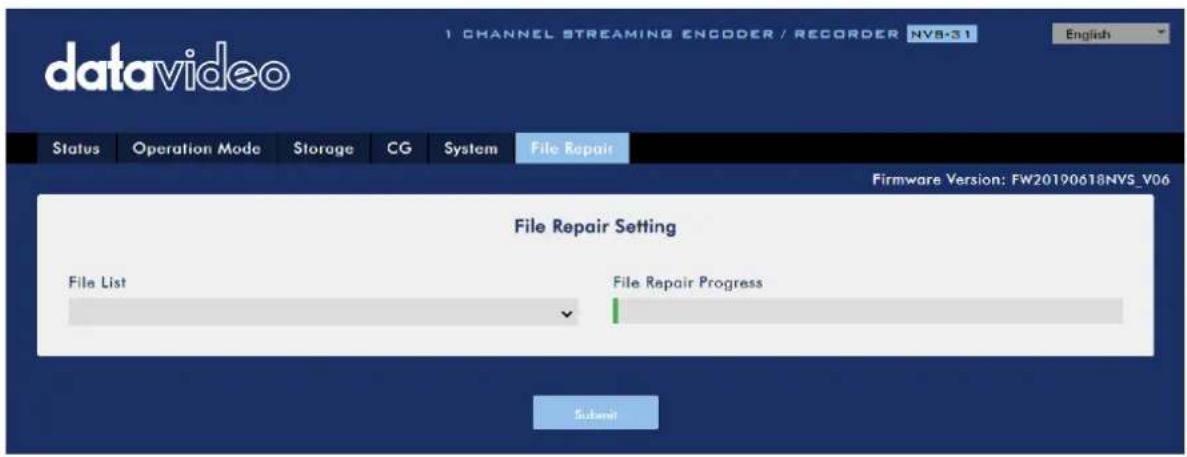
- If the MP4 file can be repaired, you will see a pop-up dialogue box prompting "MP4_FIX_OK", click OK then the "Submit" button.
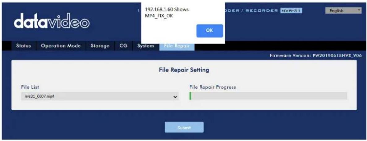
Note: If the selected MP4 file cannot be repaired, a dialogue box prompting "MP4_FIX_ERROR_MDATA" will pop up.
- The file is repaired when you see a dialogue box prompting "File repair finish!!". Click OK and reboot the NVS-31.
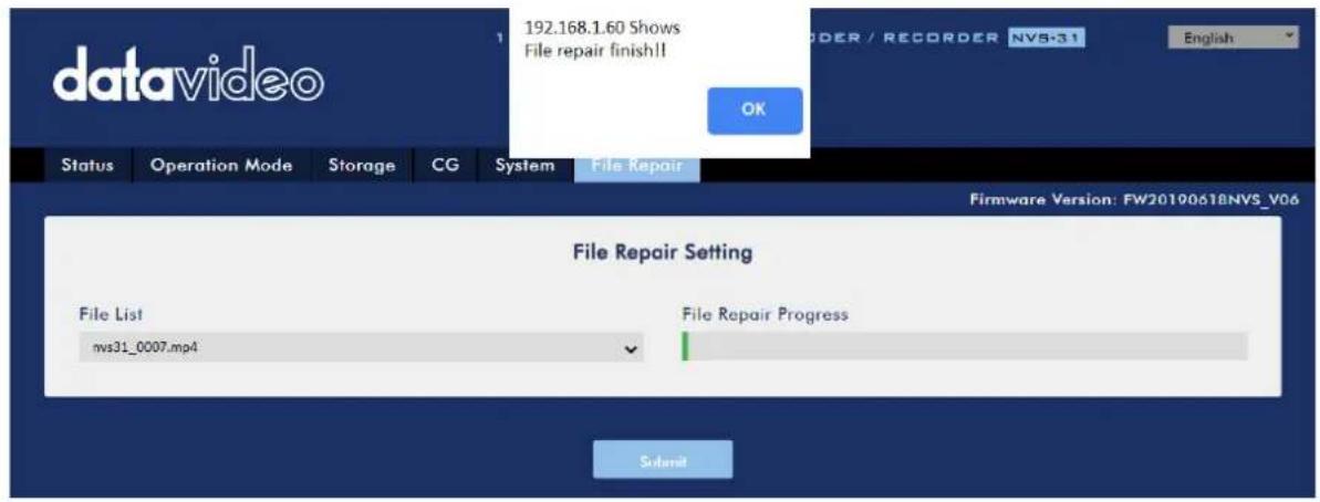
- After the NVS-31 successfully reboots, you will see the repaired file with the file name of the damaged file appended of the word "new".
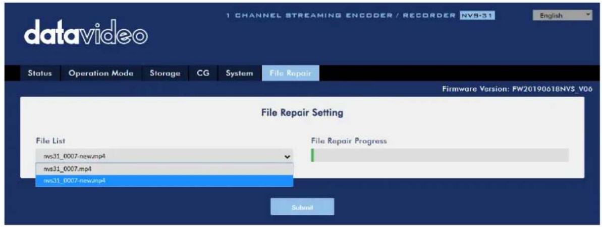
7.3 Operations
In this section, we will discuss how you can play the video using different streaming protocols and how to place texts on your video.
Video Streaming
The NVS-31 provides the user with different video streaming options such as RTSP, TS, RTMP(S), HLS, and SRT.
This section discusses settings of these options and how to stream your video using these methods.
RTSP/TS/HLS/SRT
In the RTSP/TS/HLS/SRT modes, the NVS-31 is a stream server which allows any client device to connect and playback your video stream. However, if you would like to stream to multiple client devices, we recommend using a separate media server to set up your streaming environment.

The following operation procedure uses VLC media player to playback video stream. If your PC or laptop does not have VLC media player installed, please visit
VideoLAN's official homepage (https://www.videolan.org/) and download the installation file then install the program.
Follow the steps below to obtain the RTSP URL:
- Open the stream settings page
- Select RTSP

- Click the Start button to generate the RTSP URL.
- Based on your settings, the device will automatically generate the RTSP URL.
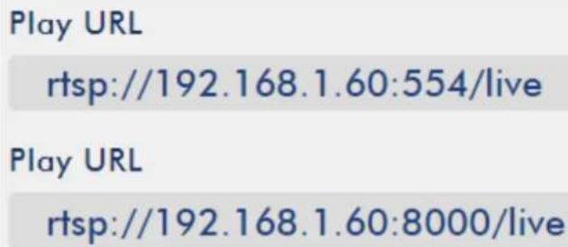
- Before streaming the video via RTSP, enter the RTSP URL into the client device.
- Open VLC then click Open Network Stream (shown in the diagram below).
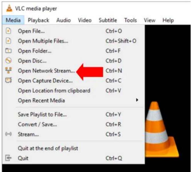
- As shown in the diagram below, enter the stream URL then click Play to start streaming.
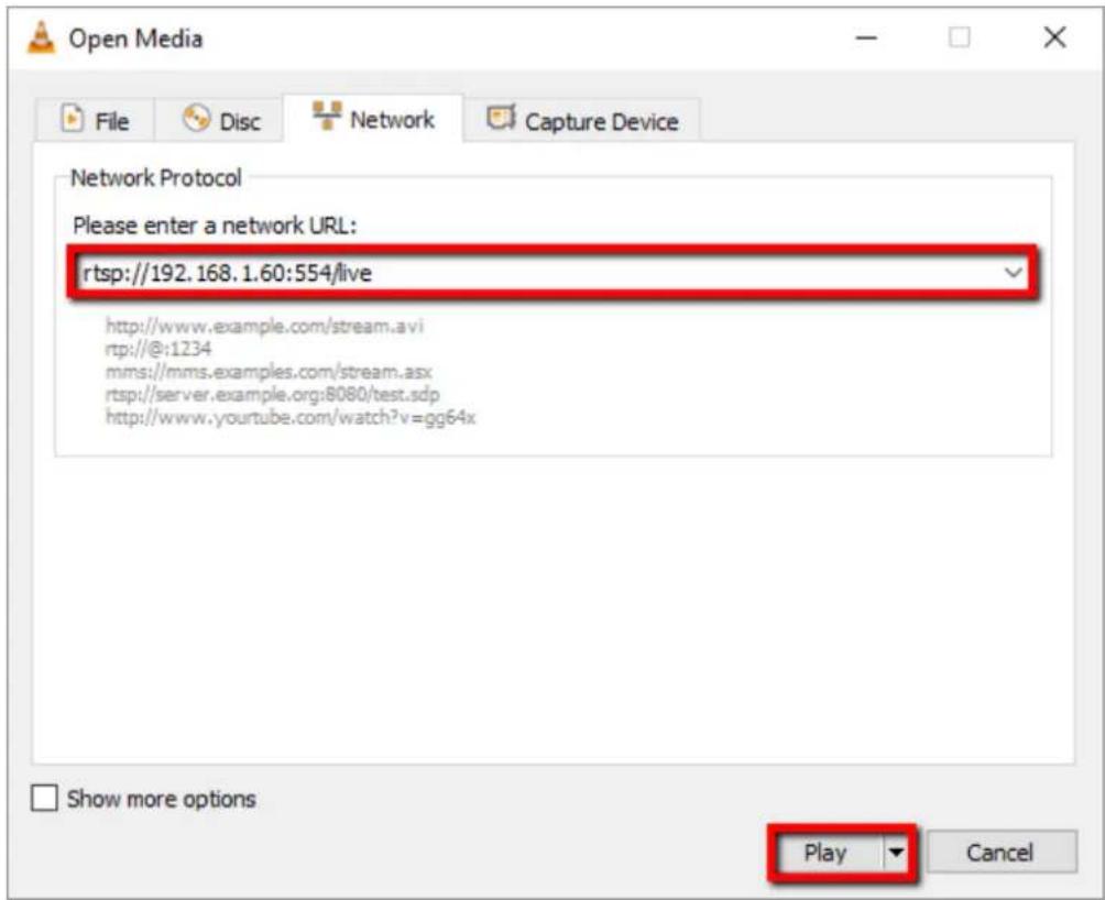
Follow the steps below to obtain the TS URL:
- Open the stream settings page
- Select TS.
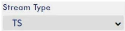
- Enter the TS port number which is 12345 by default.
TS Port
12345
- In the TS IP field, enter your PC's IP address such as 192.168.1.66.
TS IP
192.168.1.66
- Click the Start button to generate the TS URL which, in this example, will be udp://@192.168.1.66:12345 as shown in the diagram below.
Play URL
udp://@192.168.1.66:12345
- Before streaming the video via TS, enter the TS URL into the client device.
- Open VLC then click Open Network Stream (shown in the diagram below).
- As shown in the diagram below, enter the stream URL then click Play to start streaming.
Follow the steps below to obtain the HLS URL:
- Open the stream settings page
- Select HLS
Stream Type
HLS
- Click the Start button to generate the HLS URL.
Start
- Based on your settings, the device will automatically generate a .m3u8 stream URL as shown below.
Play URL
http://192.168.1.60/hls/index.html
Play URL
http://192.168.1.60/hls/live.m3u8
- Before streaming the video via HLS, enter the HLS URL into the client device.
- Open VLC then click Open Network Stream (shown in the diagram below).
- As shown in the diagram below, enter the stream URL then click Play to start streaming.
-
You can also play .m3u8 stream URL using the devices listed as follows:
-
iPhone, iPad and MacBook: Use Safari to open the .m3u8 stream URL.
- Windows 10: Use Microsoft Edge to open the .m3u8 stream URL.
Follow the steps below to obtain the SRT URL:
- Open the stream settings page
- Select SRT and the SRT port number is 9001 by default.
| Stream Type | SRT Port |
| SRT | 9001 |
- Click the Start button to generate the SRT URL.
- Before streaming the video via SRT, enter the SRT URL into the client device.
- Open VLC then click Open Network Stream (shown in the diagram below).
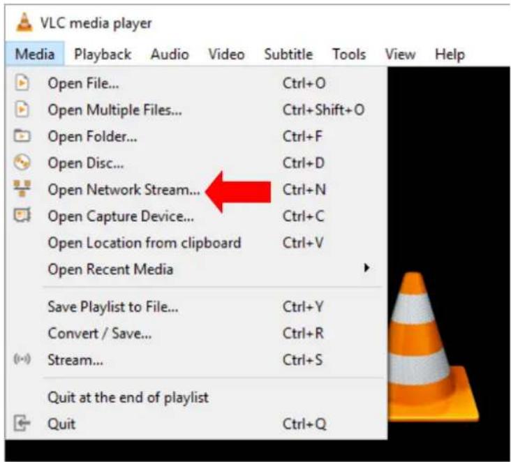
- As shown in the diagram below, enter the stream URL then click Play to start streaming.
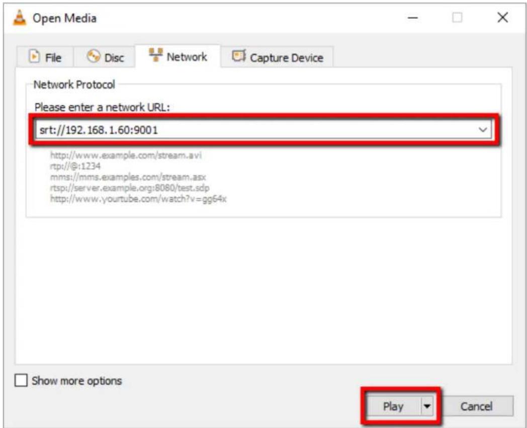
RTMP(S)
In the RTMP(S) mode, the NVS-31 can only send one data stream to one CDN or media server that supports the Real-Time Messaging Protocol or the Real-Time Messaging Protocol over an TLS/SSL connection. Examples of the RTMP(S) media server are USTREAM and Youtube.
Note: The NVS-31 supports RTMP(S) only and not the RTMP(S) local.
In the following section, we will show you how to set up an RTMP(S) stream to Youtube. The step-by-step account setup is outlined as follows:
- First of all, you have to obtain Server URL and Stream name/key from Youtube.
- Open the Youtube Live Dashboard https://www.youtube.com/live_dashboard
- On the left column, locate and click "Stream now."
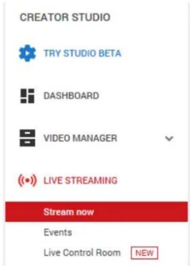
- On the right, scroll down to the bottom where you will be able to find Server URL and Stream name/key.
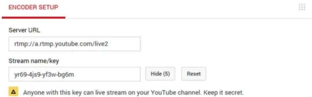
- On the NVS-31, open the Stream Only operation mode page.
- Select RTMP from the Stream Type drop-down menu.
Stream Type
RTMP

- Enter the Server URL (rtmp://a.rtmp.youtube.com/live2) obtained from the Youtube Live Streaming page into the RTMP URL field.
RTMP URL
- Enter the Stream name/key (yr69-4js9-yf3w-bg6m) obtained from the Youtube Live Streaming page into the StreamName field.
StreamName
- As required by the live streaming channel, enter your Youtube account name and password into the Account and Password fields.
| Account | Password |
- Click the Start button to start streaming the live video on the Youtube Live Streaming page. You should also see an RTMP URL generated.
- The RTMP URL is another alternative that allows you to view the live stream on a web browser. Enter the RTMP URL into the web browser's address bar then hit the Enter button to open the live video stream.
- Click the Stop Stream button to stop live streaming.
Tip: You are allowed to stream audio or video only.
Text Overlay Video
The HS-3200's built-in video streaming server not only allows you to stream and record your program, it also features a CG tool that is capable of overlaying text on the video currently being broadcast.
The CG settings page is shown below:
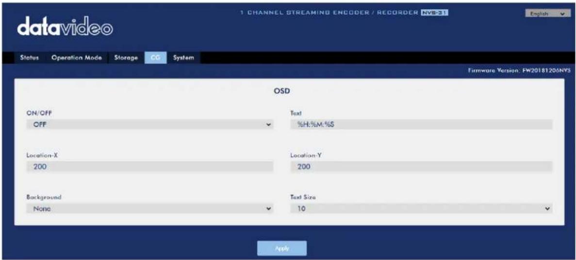
Follow the steps below to overlay text on the video:
- Open the CG settings page.
- Enable the CG function.
- In the Text field, enter the overlay text.
- Enter the X and Y coordinates to set the text position.
- Click the Apply button to save the new settings.
Note: Increasing the X coordinate moves the overlay text to the right and decreasing the X coordinate moves the overlay text to the left; increasing the Y coordinate moves the overlay text up and decreasing the Y coordinate moves the overlay text down.
7.4 Stream and Record Buttons
Before you start reading this section, first check the streaming button row located to the right of the SD card slot. If your HS-3200 is a four button model, feel free to skip the two button section.
Two Button Model
The RECORD and STREAM buttons on the front panel of the HS-3200 give the user certain controls of the record and stream functions. In this section, we will cover operations of these two buttons in detail.
Button LED behaviors and their corresponding states are listed in the table below:
| RECORD Button | STREAM Button | |
| Solid White | Record function in idle state | Stream function in idle state |
| Blinking Red | Record function is activating or resetting | Stream function is activating or resetting |
| Solid Red | Record function activated | Stream function activated |
Record Button
Press the RECORD button to start/stop recording.
Start recording
- When idle, the RECORD button is solid white.
- Press and hold the RECORD button for approximately 2 seconds.
- When the record function is activating, the RECORD button turns from solid white, then blinking red and finally to solid red.
- When the RECORD button is solid red, this indicates that the record function has been successfully activated.
Note: The RECORD button is disabled in the Stream Only mode.
Stop recording
• While recording, the RECORD button is solid red.
- Press and hold the RECORD button for approximately 2 seconds.
- When the record function is terminating, the RECORD button turns from solid red, then blinking red and finally to solid white.
- When the RECORD button is solid white, this indicates that the record function has been successfully terminated.
Stream Button
Press the STREAM button to start/stop streaming.
Start streaming
- When idle, the STREAM button is solid white.
- Press and hold the STREAM button for approximately 2 seconds.
- When the stream function is activating, the STREAM button turns from solid white, then blinking red and finally to solid red.
- When the STREAM button is solid red, this indicates that the record function has been successfully activated.
Note: The STREAM button is disabled in the Record Only mode.
Stop streaming
- While streaming, the STREAM button is solid red.
- Press and hold the STREAM button for approximately 2 seconds.
- When the stream function is terminating, the STREAM button turns from solid red, then blinking red and finally to solid white.
- When the STREAM button is solid white, this indicates that the stream function has been successfully terminated.
Operation Mode
Checking the NVS-31's operation mode
- First make sure the stream and record functions are in idle state, i.e. STREAM and RECORD buttons are solid white.
- Press RECORD or STREAM button.
- The button LED should behave according to the device's operation mode. The LED behaviors are summarized in the table below:
| Solid red RECORD button | Solid white RECORD button | |
| Solid redSTREAM button | Stream & Record | Stream Only Mode |
| Solid whiteSTREAM button | Record Only Mode | None |
- The two buttons turn solid white a few seconds after displaying the operation mode.
Switching operation modes
- First make sure the stream and record functions are in idle state, i.e. STREAM and RECORD buttons are solid white.
- Simultaneously press and hold the RECORD and STREAM buttons for more than 3 seconds but less than 10 seconds.
- As the operation mode switches, both the RECORD and STREAM buttons turn from solid red, then blinking red and finally to solid white.
- When the RECORD and STREAM buttons turn solid white, it indicates that the NVS-31 has been switched to the next operation mode successfully.
Note: The order of the operation mode change is Stream & Record → Stream Only → Record Only
Checking the next operation mode
If you do not know the NVS-31's current operation mode, follow the steps below to check the next operation mode before switching.
- First make sure the stream and record functions are in idle state, i.e. STREAM and RECORD buttons are solid white.
- Simultaneously press and hold the RECORD and STREAM buttons for more than 1 second but less than 3 seconds.
- The button LED should behave according to the device's next operation mode. The LED behaviors are summarized in the table below:
| Solid red RECORD button | Solid white RECORD button | |
| Solid redSTREAM button | Stream & Record | Stream Only Mode |
| Solid whiteSTREAM button | Record Only Mode | None |
- The two buttons turn solid white a few seconds after displaying the operation mode.
Note: The order of the operation mode change is Stream & Record → Stream Only → Record Only
Four Button Model
The RECORD, STREAM, RECORD+STREAM and BITRATE buttons on the front panel of the HS-3200 give the user certain controls of the record and stream functions. In this section, we will cover operations of these four buttons in detail.
Button LED behaviors and their corresponding states are listed in the table below:
| RECORD Button | STREAM Button | RECORD+STREAM Button | |
| Solid White | Record function in idle state | Stream function in idle state | Record/Stream functions in idle state simultaneously |
| Blinking Red | Record function is activating or resetting | Stream function is activating or resetting | Record/Stream functions are activating or resetting simultaneously |
| Solid Red | Record function activated | Stream function activated | Record/Stream functions are activated simultaneously |
Record Button
Press the RECORD button to start/stop recording.
Start recording
- When idle, the RECORD button is solid white.
- Press and hold the RECORD button for approximately 2 seconds.
- When the record function is activating, the RECORD button turns from solid white, then blinking red and finally to solid red.
- When the RECORD button is solid red, this indicates that the record function has been successfully activated.
Note: The RECORD button is disabled in the Stream Only mode.
Stop recording
• While recording, the RECORD button is solid red.
- Press and hold the RECORD button for approximately 2 seconds.
- When the record function is terminating, the RECORD button turns from solid red, then blinking red and finally to solid white.
- When the RECORD button is solid white, this indicates that the record function has been successfully terminated.
Stream Button
Press the STREAM button to start/stop streaming.
Start streaming
- When idle, the STREAM button is solid white.
- Press and hold the STREAM button for approximately 2 seconds.
- When the stream function is activating, the STREAM button turns from solid white, then blinking red and finally to solid red.
- When the STREAM button is solid red, this indicates that the record function has been successfully activated.
Note: The STREAM button is disabled in the Record Only mode.
Stop streaming
• While streaming, the STREAM button is solid red.
- Press and hold the STREAM button for approximately 2 seconds.
- When the stream function is terminating, the STREAM button turns from solid red, then blinking red and finally to solid white.
- When the STREAM button is solid white, this indicates that the stream function has been successfully terminated.
Record+Stream Button
Start recording/streaming simultaneously
- When idle, the RECORD+STREAM button is solid white.
- Press and hold the RECORD+STREAM button for approximately 2 seconds.
- When the record and stream functions are activating simultaneously, the RECORD+STREAM button turns from solid white, then blinking red and finally to solid red.
- When the RECORD+STREAM button is solid red, this indicates that the record and stream functions have been successfully activated.
Stop recording/streaming simultaneously
- While recording and streaming simultaneously, the RECORD+STREAM button is solid red.
- Press and hold the RECORD+STREAM button for approximately 2 seconds.
- When the record and stream functions are terminating, the RECORD+STREAM button turns from solid red, then blinking red and finally to solid white.
- When the RECORD+STREAM button is solid white, this indicates that the record and stream functions have been successfully terminated.
Bitrate Button
Follow the steps below to switch the stream bitrate mode using the BITRATE button:
- Press and hold one of the RECORD+STREAM button, the RECORD button, and the STREAM button until the pressed button starts blinking red.
- Continue holding down one of the RECORD+STREAM button, the RECORD button, and the STREAM button while pressing the BITRATE button to switch stream bitrate mode (H, M or L).
Note: The system will return to original settings if the BITRATE button push is not sensed. The default bitrate is M.
Operation Mode
Checking the NVS-31's operation mode
Follow the steps below to check the NVS-31's current operation mode:
- First make sure the stream and record functions are in idle state, i.e. STREAM and RECORD buttons are solid white.
- Press RECORD or STREAM button.
- The button LED should behave according to the device's operation mode. The LED behaviors are summarized in the table below:
| Solid red RECORD button | Solid white RECORD button | |
| Solid red STREAM button | Stream & Record | Stream Only Mode |
| Solid white STREAM button | Record Only Mode | None |
- The two buttons turn solid white a few seconds after displaying the operation mode.
Switching operation modes
Follow the steps below to switch to the next operation mode:
- First make sure the stream and record functions are in idle state, i.e. STREAM and RECORD buttons are solid white.
- Simultaneously press and hold the RECORD and STREAM buttons for more than 3 seconds but less than 10 seconds.
- As the operation mode switches, both the RECORD and STREAM buttons turn from solid red, then blinking red and finally to solid white.
- When the RECORD and STREAM buttons turn solid white, it indicates that the NVS-31 has been switched to the next operation mode successfully.
Note: The order of the operation mode change is Stream & Record → Stream Only → Record Only
Checking the next operation mode
Follow the steps below to check the operation mode next to the NVS-31's current operation mode before switching:
- First make sure the stream and record functions are in idle state, i.e. STREAM and RECORD buttons are solid white.
- Simultaneously press and hold the RECORD and STREAM buttons for more than 1 second but less than 3 seconds.
- The button LED should behave according to the device's next operation mode. The LED behaviors are summarized in the table below:
| Solid red RECORD button | Solid white RECORD button | |
| Solid red STREAM button | Stream & Record | Stream Only Mode |
| Solid white STREAM button | Record Only Mode | None |
- The two buttons turn solid white a few seconds after displaying the operation mode.
Note: The order of the operation mode change is Stream & Record → Stream Only → Record Only
7.5 Restoring Factory Defaults
Follow the steps below to restore the NVS-31's factory defaults.
- The RECORD and STREAM buttons are either solid white and solid red, which means the factory defaults can be restored regardless of the state of the device.
- Press and hold the RECORD and STREAM buttons simultaneously for more than 10 seconds.
- While the NVS-31's factory defaults are being restored, both the RECORD and STREAM buttons turn from solid red, then blinking red and finally to solid white.
- When the RECORD and STREAM buttons turn solid white, it indicates that the NVS-31's factory defaults have been successfully restored.
7.6 Firmware Update
Datavideo usually releases new firmware containing new features or reported bug fixes from time to time. This section outlines the firmware upgrade process which should take approximately 10 minutes to complete. See Appendix 4 for instructions.
Chapter 8 Monitor OSD MENU
The HS-3200 Monitor can be configured via an on screen menu. When the MENU button is pressed the Main Menu list is displayed on the monitor.
This section covers the Menu options in the order that they appear on the monitor. These settings may also appear in more detail elsewhere in this instruction manual. Options may vary depending on the firmware version in use.
Once the chosen setting has been confirmed with the ENTER button, it is stored within the switcher's non-volatile memory.
| Main Options | Sub Options | Parameters | Parameters |
| MAIN ADJUST | BRIGHTNESS | 0~100 | |
| CONTRAST | 0~100 | ||
| SHARPNESS | 0~100 | ||
| SATURATION | 0~100 | ||
| TINT | 0~100 | ||
| BACK LIGHT | 0~100 | ||
| NR | HIGH / MID / LOW / OFF | ||
| MPEG NR | HIGH / LOW / OFF | ||
| VOLUME | 0~100 | ||
| EXIT | |||
| COLOR | 6500 | ||
| 9300 | |||
| 7500 | |||
| USER COLOR | RED | 0~100 | |
| GREEN | 0~100 | ||
| BLUE | 0~100 | ||
| EXIT | |||
| SCAN SETTING | UNDER SCAN | full image | |
| OVER SCAN | cropped image | ||
| INFORMATION | H. FREQUENCY | ||
| V. FREQUENCY | |||
| RESOLUTION | |||
| VER. | |||
| LANGUAGE | English [default] | ||
| Francis | |||
| Deutsch | |||
| Español | |||
| Italiano | |||
| Dutch | |||
| Português | |||
| Russian | |||
| EXIT | |||
| SPECIAL FUNCTION | OSD TIMOUT | 5-120 SEC | |
| FRAME RATIO | 80 / 90 / OFF | ||
| 4:3 MARK LINE | ON / OFF | ||
| CENTRAL MARK | ON / OFF | ||
| CINEMA ZONE MARK | ON / OFF | ||
| EXIT | |||
| FACTORY RESET | |||
| EXIT | |||
8.1 Main Adjust
The first menu option is the MAIN ADJUST.
To access the MAIN ADJUST sub-menu, press enter and the Brightness sub-option will be highlighted.
To adjust BRIGHTNESS press Enter again. Use the Up / Down buttons to change the setting and then press Enter to store the new value and return to the main menu.
Use the Up / Down buttons to select a different setting (Brightness, Contrast, Saturation, Sharpness, TINT and etc). Follow the same procedure to set other values.
8.2 Color
Press the MENU button to access the menu and use the Up / Down buttons to move to the COLOR option so that it is highlighted. Press the ENTER button to open the COLOR submenu.
To access the selected color setting, press ENTER again.
Use the Up / Down buttons to navigate the available color settings.
The System Information Menu displays Horizontal Frequency, Vertical Frequency, Resolution and the monitor's version of firmware.
Once selected, the information will be displayed as follows:
• H. FREQUENCY 33.7KHZ
• V. FREQUENCY 60.0HZ
• RESOLUTION 1920X1080I
• VER. 0.11
8.4 Special Function
The Special Function Sub-Menu has settings for the OSD TIMEOUT, Frame Ratio, 4:3 MARK LINE, Central Mark, and Cinema Zone Mark.
To access the selected setting press the ENTER button.
Use the Up / Down buttons to navigate the available options.
- OSD TIMEOUT 5-120 SEC
• FRAME RATIO 90 / 80 / OFF
• 4:3 MARK LINE ON / OFF
• CENTRAL MARK ON / OFF
• CINEMA ZONE MARK ON / OFF
8.5 Factory Reset
The monitor menu offers a Factory Reset option, which will return all the settings of the monitor to the factory defaults
To reset the monitor press the MENU button and then use the UP / Down button to navigate to FACTORY RESET option. Press ENTER again to reset the monitor. After a few seconds the monitor will be reset.
Chapter 9 Appendices
Appendix 1 Tally Outputs
The HS-3200 has a D-sub 25 pin female tally output port. These connections provide bi-colour tally information to a number of other Datavideo products, such as the ITC-100 eight channel talkback system and the TLM range of LCD Monitors.
These ports are open collector ports and as such do not provide power to tally light circuits.
Dielectric strength: Max. DC 24V
Current:
Max. 50mA
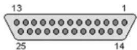
(D-sub 25-Pin Female)
The pin outputs are defined as follows:
| Pin No. | Signal name | Input/Output | Signal Description |
| 1 | Program 1 | Open collector output | Tally output of input video Program 1 |
| 2 | Program 2 | Open collector output | Tally output of input video Program 2 |
| 3 | Program 3 | Open collector output | Tally output of input video Program 3 |
| 4 | Program 4 | Open collector output | Tally output of input video Program 4 |
| 5 | Program 5 | Open collector output | Tally output of input video Program 5 |
| 6 | Program 6 | Open collector output | Tally output of input video Program 6 |
| 7 | Program 7 | Open collector output | Tally output of input video Program 7 |
| 8 | Program 8 | Open collector output | Tally output of input video Program 8 |
| 9 | Program 9 | Open collector output | Tally output of input video Program 9 |
| 10 | Program 10 | Open collector output | Tally output of input video Program 10 |
| 11 | Program 11 | Open collector output | Tally output of input video Program 11 |
| 12 | Program 12 | Open collector output | Tally output of input video Program 12 |
| 13 | GND | Ground | Ground |
| 14 | Preset 1 | Open collector output | Tally output of input video Preset 1 |
| 15 | Preset 2 | Open collector output | Tally output of input video Preset 2 |
| 16 | Preset 3 | Open collector output | Tally output of input video Preset 3 |
| 17 | Preset 4 | Open collector output | Tally output of input video Preset 4 |
| 18 | Preset 5 | Open collector output | Tally output of input video Preset 5 |
| 19 | Preset 6 | Open collector output | Tally output of input video Preset 6 |
| 20 | Preset 7 | Open collector output | Tally output of input video Preset 7 |
| 21 | Preset 8 | Open collector output | Tally output of input video Preset 8 |
| 22 | Preset 9 | Open collector output | Tally output of input video Preset 9 |
| 23 | Preset 10 | Open collector output | Tally output of input video Preset 10 |
| 24 | Preset 11 | Open collector output | Tally output of input video Preset 11 |
| 25 | Preset 12 | Open collector output | Tally output of input video Preset 12 |
Example of tally connections
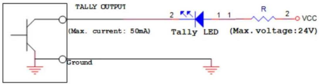
Appendix 2 GPI / GPO Connections
The HS-3200 can control external recorder/playback devices like the HDR-45 and HDR-55 via a simple contact closure GPI / GPO switch.
The GPI interface is a 3.5mm Jack Socket which is situated on the rear panel of the HS-3200. Contact closure between the Outer and Inner contacts on the jack plug will trigger a user selected event. Power is supplied by the HS-3200 and is less than 5V DC.
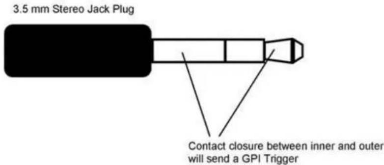
This GPI socket can also be used as a GPO socket to trigger record or playback events with other equipment such as the Datavideo HDR-70 recorder.
SAFETY FIRST The cabling required needs to be designed specifically to connect the HS-3200 to the chosen record or playback device as they are not all the same. The cabling required can be made by yourself or a competent technician. Please speak with your Dealer or local Datavideo office to get further help and advice.
Appendix 3 Recommended SD Cards
You should only use Class 10 SD card or above. In this appendix, you will find a list of SD cards recommended by Datavideo.
| Recommended SD Cards | |||
| No. | Brand | Model | Pictures |
| 1 | Kingston | SDHC | C10 16GB |  |
| 2 | SANDISK Extreme | SDXC | C10 U3 V30 64GB |  |
| 3 | SONY | SDXC | C10 U1 64GB |  |
| 4 | SANDISK Extreme PRO | SDXC | C10 U3 128GB/64GB |  |
 | |||
| 5 | SONY | SDXC | C10 U3 64GB |  |
| 6 | TOSHIBA | SDHC C10 16GB |  |
| 7 | SANDISK Extreme | SDHC C1016GB |  | |
| 8 | ADATA Premier Pro | microSDXC I UHS-I U3 Class 10 with SD adapter64GB/16GB |  | |
 | ||||
| 9 | SANDISK ULTRA® | SDHCTM/SDXCTM UHS-I128GB |  | |
| 10 | Transcend | 300S UHS-I SDHC64GB/32GB |  | |
 |
Appendix 4 Firmware Update
Datavideo usually releases new firmware containing new features or reported bug fixes from time to time. Customers can either download the HS-3200 firmware as they wish or contact their local dealer or reseller for assistance.
This section outlines the firmware upgrade process which should take approximately 1 hour 20 minutes to complete.
The existing HS-3200 settings should persist through the firmware upgrade process, which should not be interrupted once started as this could result in a non-responsive unit.
Switcher
Successful firmware upgrade on HS-3200 requires:
PC or laptop
USB drive
- Access to the Internet for software download
Steps to update the HS-3200 firmware:
- Download the latest firmware and the update tool from the path below.
www.datavideo.com → products → Switchers → HS-3200 → Downloads → Latest Firmware
- Decompress the downloaded files.
- Insert the USB drive into the PC or laptop and format the drive to FAT or FAT32 system. Save the latest firmware on the drive.
- Remove the USB drive from the PC or laptop.
- Insert the USB drive into the F/W Upgrade port at the rear of the HS-3200 switcher.
- Press the MENU button on the HS-3200 control panel to open the OSD menu.
- At the bottom of the Main Menu, enter the SETUP sub menu.
- Under the Software option, select "Upgrade" and press the ENTER button to confirm.
- If you see "Upgrade" against a red background, it means the switcher is being updated.
- When you see red turned to green, it means the firmware upgrade is successful.
- Reboot the HS-3200 switcher to complete the upgrade.
Video Streaming Server
You should first visit the official product page https://www.datavideo.com/tw/product/HS-3200 where you can download the latest firmware file. Then follow the steps outlined below to update the device firmware.
- Login the NVS-31 web interface, then click the System tab to open the system configuration page.
- Scroll down to Firmware Update then click the Browse button to search for the latest firmware file on the PC's hard disk.
- After double clicking the firmware file, you will see the loading prompt as shown below, indicating that the file is being uploaded to the NVS-31.
- After the file has been successfully uploaded, you will see a file upload success message. Click the Update button to start the firmware update process.
- The device will reboot itself after it is updated successfully.

Note: If the device is recording or streaming, you must turn them off before initiating the firmware update.
Recovery Mode
If power outage is experienced while the firmware is being updated and the NVS-31 becomes inaccessible due to incomplete update or corrupt files, you may reboot the HS-3200 then activate the recovery mode to restore the device functionality. Follow the steps below to enter the recovery mode.
- Reboot the HS-3200
- As the HS-3200 boots, the STREAM button turns solid red then press and hold the RECORD and STREAM buttons simultaneously; release them when the two buttons start flashing red color.
- The NVS-31 starts erasing files of the previous update and uses the previously uploaded file to force the firmware update.
- When the RECORD and STREAM buttons turn solid white, the firmware update is complete.
Formatting the SD Card
You are also allowed to format the SD card on the HS-3200. Follow the steps below to format your SD card.
- Insert the SD card into the HS-3200's SD card slot.
- Login the NVS-31 web interface then click the Storage tab to open the storage interface.
- Select the disk storage format from the Storage Format drop-down list.
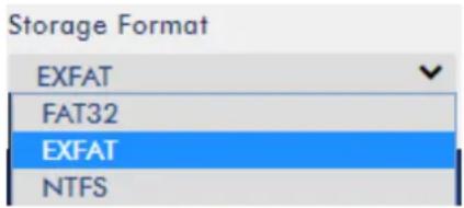
- Click the Format Storage Disk button to start SD card formatting. The format is complete when the progress bar reaches 100%.
Format Storage Disk
Appendix 5 Frequently-Asked Questions
This section describes problems that you may encounter while using the HS-3200. If you have any questions, please refer to related sections and follow all suggested solutions. If problem still exists, please contact your distributor or the service center.
| No. | Problems | Solutions |
| 1 | Grabbed picture is distorted or contains noise. | Successfully grabbed pictures to Still 1 and 2 will be distorted or appear noisy if switched to different video standards. |
| 2 | Loaded still picture contains noise. | Still pictures will be distorted or appear noisy if switched to different video standards. |
| 3 | What kind of files can be saved on the HS-3200 and is there any limitation? | You can save still pictures, user memory, clips and logos to the HS-3200's memory but the maximum storage space is limited to 1000 frames. |
| 4 | One of the FLEX sources is not displayed in the FLEX windows. | The maximum FlexTM output size is 1080p full screen. If exceeded, one Flex source will not be displayed. |
| 5 | HS-3200 is unable to save the last settings into its nonvolatile memory. | The Last Memory feature will be enabled upon entering and exiting the OSD menu. Only shut down the machine after 10 seconds after the OSD menu is closed (It takes 10 seconds for the HS-3200 to finish saving the last settings to the memory). |
| 6 | Why am I seeing black thin lines on PIP images? | These black thin lines are caused by using an image that differs from its original size. To remove these black thin lines, turn the border OFF or use thePIP Crop function to shrink the image until they disappear. |
Appendix 6 Dimensions
Main Unit
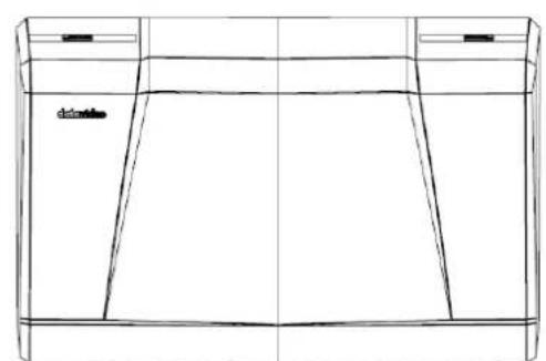
natural_image
Line drawing of a rectangular container with internal compartments and a small label on the side (no text or symbols)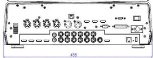
natural_image
Back panel diagram of a computer interface showing ports, connectors, and ports without any readable text or symbols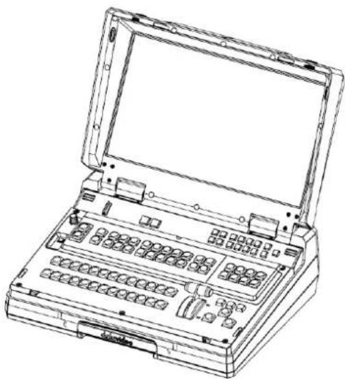
natural_image
Line drawing of a laptop case with open lid and internal compartments (no text or symbols)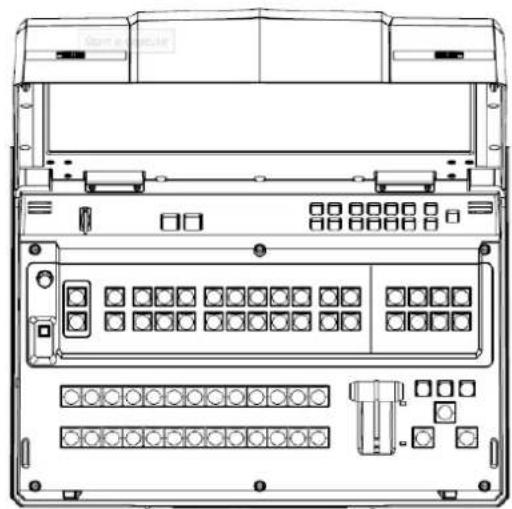
natural_image
Technical line drawing of a server rack with ports, connectors, and indicator lights (no text or labels)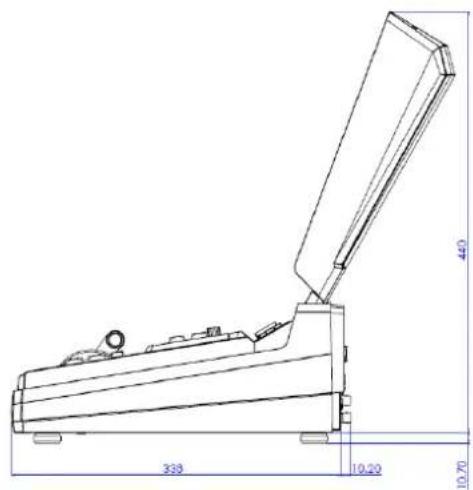
Appendix 7 Specifications
| Model Name | HS-3200 |
| Product Name | HD 12-Channel Digital Video Switcher |
| Video Standard | Full HD |
| Video Format | 1080p 50/59.94/60Hz1080i 50/59.94/60Hz720p 50/59.94/60Hz |
| Input Routable / Crosspoint | All 12, repeatable |
| Video Input | 8 x SDI4 x HDMI |
| Computer Graphical Interface | 4 via HDMI |
| Down-Converted Output | 1 x SDI |
| Video Output | 5 x SDI, 1 x HDMI assignable:MultiviewPGMPVWPGM+DSKClean PGMClean PVWInput 1-12STILL 1STILL 2Flex source3 x HDMI PGM only |
| Analogue Audio Input | 4 x Balanced XLR |
| Analogue Audio Output | 2 x Balanced XLR |
| Digital Embedded Audio Support Input | Input 2 ChannelsOutput 4 Channels |
| Audio Delay Calibration | up to 16 frames |
| A+V Switching | Yes |
| USK | 4 |
| DSK | 2 x DSK supporting Lumakey & Linear key (Key / Fill) |
| Picture in Picture | 8 (4 x Keyer / 4 x Flex Source) |
| Logo Insertion | 2 |
| Title Creator | Yes, CG-200 software free download |
| Built-in Monitor Display | 17.3" HD TFT LED Backlit, 1920x1080 pix |
| Streaming Video Encode | H.264 / AVC, Main/High Profile Configurable Bitrate up to 10Mbps |
| Streaming Audio Encode | AAC-LCConfigurable bitrate range from 32 Kbps to 384 KbpsSample Rate: 48 kHz, 16 bit |
| Streaming Protocol | TS over TCP/UDP (Unicast & Multicast)RTSP over HTTP/TCP/UDPRTMP/RTMPS (Publish)HLSSRT |
| Streaming Control | Web browser UI for configuration and control socket commands |
| Recording File System | FAT, exFAT, NTFS |
| Recording File Format | MP4 |
| Streaming & Recording Setting Control | Web UI for system configuration and control |
| Special Features | 4 Chroma-Key Virtual Studio9 Stinger transition and 4 user presetsBuilt-in TC-200 CG interfaceStreaming encoder and recorder12x9 matrix seamless switch |
| Dimensions (LxWxH) | 455 x 355 x 134 mm |
| Weight | 17.8 Lbs (8.1 kg), Reinforced Plastic Case |
| Power | DC 12V, 11A |
| Operating Temperature | 0 – 40°C |
| Accessory | TPC-700, CB-22H/23H/46/47/60/61/62 |
Notes
Notes
Service & Support
It is our goal to make owning and using Datavideo products a satisfying experience. Our support staff is available to assist you to set up and operate your system. Contact your local office for specific support requests. Plus, please visit www.datavideo.com to access our FAQ section.
Please visit our website for latest manual update.
- Table of Contents
- CHAPTER 5 BASIC OPERATION....72
- CHAPTER 6 ADVANCED OPERATION....96
- CHAPTER 7 VIDEO STREAMING AND RECORDING....114
- CHAPTER 8 MONITOR OSD MENU 155
- CHAPTER 9 APPENDICES....158
- Disclaimer of Product & Services
- FCC Compliance Statement
- Warnings and Precautions
- Warranty
- Standard Warranty
- Three Year Warranty
- Disposal
- For EU Customers only - WEEE Marking
- Chapter 1 Introduction
- Major features
- Summary of all features
- Rear Panel Overview
- Control Panel Overview
- Connecting the Power Supply
- Chapter 2 Preparation
- Connecting Devices
- Connecting the Video and Audio Input Devices
- When linking via tally connection
- Connecting the Video and Audio Output Devices
- Connecting to a Network
- Multi View
- Chapter 3 Network and Software Setup for Switcher
- Static IP Configuration
- Instructions
- DHCP Mode
- Open Switcher Image Import/Export Software
- Home
- User
- Still
- Clip
- Logo
- Ani-Logo
- Setup
- Chapter 4 OSD MENU
- Start
- Transition
- Type
- Wipe Effects
- WIPE Border
- Position
- Horizontal Position (X)
- Vertical Position (Y)
- Matte
- Keyer
- Keyer
- Keyer Control
- Please note:
- If P-in-P is selected, adjust its parameters in the P-in-P sub menu.
- Key Source
- Fill Source
- Invert
- Mask
- Chroma
- Key Tie
- CK Setup
- P-In-P
- Fine
- Border
- Shade Matte (Dual Color Border)
- Luma, Sat and Hue
- Shade Softness, Shade Position and Direction
- Shade Soft
- Shade Position
- Direction
- Crop
- Flex Src
- Flex Screen
- System Hardware Setup
- Menu Settings
- Flex Preset
- Preset 3
- Note: Presets 4 to 6 are reserved for future developments.
- Inputs
- Advanced mode options
- Input
- Mode of Operation
- Proc Amp
- Audio
- Crosspoint
- Audio XPT
- Outputs
- Outputs
- Multiviewer
- MV1/2
- R/L
- Tally Mode
- The HS-3200 provides two tally modes:
- GPI Out
- Audio
- PGM Audio
- Analog Out
- Files
- User Mems
- Load Memory
- Save Memory
- Load Still
- Save Still
- Grab Still
- Loading still images
- Load Clip
- Clip Settings
- Loading the existing Clip for Stinger Transition Effect
- Load Logo
- Positioning
- Ani Logo
- Load Ani Logo
- Setup
- Standard
- Note: If you've selected 720p for the output resolution, all inputs should have a resolution of 720p as well.
- Level
- Genlock
- OutConv
- Menu Mode
- Menu Preference
- Menu Position
- Auto Save
- Factory Default
- Language
- Network
- Software
- Chapter 5 Basic Operation
- Video Switching
- Program and Preset rows
- Black and MATTE View
- Flex Output
- Still button
- Transitions
- AUTO Button
- CUT Button
- MIX Button
- WIPE/DVE Button
- Clip Button
- FTB Button
- T-Bar
- WIPE Selection MENU
- Soft Value
- Width Value
- Hue, Sat and Luma values
- Wipe Position
- REV Button
- Managing Still Pictures
- Grabbing & Saving a Still to Memory
- Loading an existing Still from Memory
- Deleting a saved Still from Memory
- FS - Frame Store Button
- How to choose live video input or Frame Store
- Import Still Images from PC
- How to use
- Performing a Stinger Transition
- Loading a Clip from Memory
- Importing the Clip for Stinger Transition Effect from PC
- Importing Clips
- How to Create the PNG Sequence for Stinger Transition Effect
- Adobe After Effects
- Adobe Media Encoder CC
- Important things to note while creating Stinger Transition Effects
- Enabling Still Logo
- Importing Still Logo from PC
- Enabling Logo Animation
- Loading an existing Ani-Logo from Memory
- Importing Animated Logo from PC
- Chapter 6 Advanced Operation
- Picture-in-Picture and Downstream Key
- Picture-In-Picture
- Assigning a video source to a PIP window
- Assigning a video source to a PIP window using shortcut keys
- Character Generator
- Then follow the steps below to set up the built-in TC-200
- DSK Preview and DSK Program
- Placing text on the video using luma key
- Insertion of People onto Backgrounds (Chroma Key)
- A good foreground image helps produce a good key
- Three chip/Three sensor camera
- White Balance the Camera
- Lighting
- Displaying a variety of Sources at the same time
- Basic Flex™ Output (Four PIP Windows)
- Simultaneously Enabling up to Eight PIP Windows
- Shortcut Keys to assigning Output Sources
- Chapter 7 Video Streaming and Recording
- Streaming Network Connection and Device Search
- Connecting to a NON-DHCP Network (Static IP)
- Default Fixed IP
- Tip: If you forget or lose the IP address, do the following to reset the network settings.
- Troubleshooting the Network Connection
- Advanced Troubleshooting
- Web User Interface
- Status
- Operation Mode
- Storage
- CG
- System
- Time Setting
- Firmware Update
- Device Name Setting
- Account Setup
- System Control
- File Repair
- Operations
- Video Streaming
- RTSP/TS/HLS/SRT
- Follow the steps below to obtain the RTSP URL:
- Follow the steps below to obtain the TS URL:
- Follow the steps below to obtain the HLS URL:
- Follow the steps below to obtain the SRT URL:
- RTMP(S)
- StreamName
- Text Overlay Video
- Stream and Record Buttons
- Two Button Model
- Record Button
- Start recording
- Stop recording
- Stream Button
- Start streaming
- Stop streaming
- Checking the NVS-31's operation mode
- Switching operation modes
- Checking the next operation mode
- Four Button Model
- Record+Stream Button
- Start recording/streaming simultaneously
- Stop recording/streaming simultaneously
- Bitrate Button
- Note: The order of the operation mode change is Stream & Record → Stream Only → Record Only
- Restoring Factory Defaults
- Firmware Update
- Chapter 8 Monitor OSD MENU
- Main Adjust
- Color
- Special Function
- Factory Reset
- Chapter 9 Appendices
- Appendix 1 Tally Outputs
- Appendix 2 GPI / GPO Connections
- Appendix 3 Recommended SD Cards
- Appendix 4 Firmware Update
- Switcher
- Steps to update the HS-3200 firmware:
- Video Streaming Server
- Recovery Mode
- Formatting the SD Card
- Appendix 5 Frequently-Asked Questions
- Appendix 6 Dimensions
- Notes
- Service & Support
Brand : DataVideo
Model : HS-3200
Category : Video recorder