HDR-90 - Video recorder DataVideo - Free user manual and instructions
Find the device manual for free HDR-90 DataVideo in PDF.


| Product Type | Video Recorder |
| Brand | DataVideo |
| Model | HDR-90 |
| Dimensions (W x H x D) | 200 mm x 150 mm x 50 mm |
| Weight | 1.2 kg |
| Power Supply | DC 12V, 2A |
| Recording Format | H.264, H.265, ProRes |
| Max Resolution | 3840 x 2160p @ 60fps |
| Input Connectors | 1x HDMI, 1x SDI, 1x Composite |
| Output Connectors | 1x HDMI, 1x SDI |
| Storage Media | SD card, USB external drive |
| Display | 3.5-inch TFT LCD |
| Audio Input | 2x XLR, 1x 3.5mm jack |
| Battery Type | Rechargeable Li-ion, 7.4V |
| Battery Life | Approx. 3 hours |
| Operating Temperature | 0°C to 40°C |
| Maintenance | Clean with dry, soft cloth. Avoid solvents. |
| Safety Precautions | Keep away from moisture and heat sources. |
| Spare Parts Availability | Contact DataVideo support for replacement parts. |
| Warranty | 1 year limited warranty |
Frequently Asked Questions - HDR-90 DataVideo
User questions about HDR-90 DataVideo
0 question about this device. Answer the ones you know or ask your own.
Ask a new question about this device
Download the instructions for your Video recorder in PDF format for free! Find your manual HDR-90 - DataVideo and take your electronic device back in hand. On this page are published all the documents necessary for the use of your device. HDR-90 by DataVideo.
USER MANUAL HDR-90 DataVideo
natural_image
Line drawing of a data video rack unit with monitor, ports, and drive base (no text or symbols on main body)ProRes 4K Video Recorder
1U Rackmountable
HDR-90
Instruction Manual
Table of Contents
FCC COMPLIANCE STATEMENT....4
WARNINGS AND PRECAUTIONS......4
WARRANTY 5
STANDARD WARRANTY 5
THREE YEAR WARRANTY....6
DISPOSAL 6
1. PRODUCT OVERVIEW 7
1.1 FEATURES....7
1.2 SYSTEM DIAGRAM 8
2. CONNECTIONS AND CONTROLS....9
2.1 WITH HEADPHONE MONITORING....9
Front Panel....9
Rear Panel 11
2.2 WITHOUT HEADPHONE MONITORING 14
Front Panel....14
Rear Panel 16
3. SSD SLOTS....20
3.1 INSTALL AN SSD IN A REMOVABLE DISK ENCLOSURE....20
4. HUMAN MACHINE INTERFACE....23
4.1 DASHBOARD....24
4.1.1 Audio Indicator....27
4.1.2 Play Speed....27
4.1.3 Disk Information....28
4.1.4 Sub-Menu 29
Focus Assist....29
Zebra 30
Waveform 31
Histogram....31
Vectorscope 31
Loop Play....32
Multiview ....33
LCD Display....34
4.2 CLIP....34
4.2.1 Bin with Multiple Clips 35
4.2.2 Single Clip Deletion 36
4.2.3 Multiple Clip Deletion....37
4.3 MENU 38
4.3.1 Input....38
ProRes Quality....39
Input Channel Setup 39
PsF Setup....40
XLR Setup 41
Time Code 41
4.3.2 Control....42
4.3.3 System 42
Time Zone 43
Format SSD....44
XLR Setup 46
Reset 46
4.3.4 Info 47
- FIRMWARE UPDATE....48
FIRMWARE UPGRADE REQUIREMENTS....48
UPGRADE PROCEDURE 48
-
FREQUENTLY ASKED QUESTIONS......49
-
DIMENSIONS....51
-
PRODUCT SPECIFICATIONS 52
SERVICE & SUPPORT 56
Disclaimer of Product & Services
The information offered in this instruction manual is intended as a guide only. At all times, Datavideo Technologies will try to give correct, complete and suitable information.
However, Datavideo Technologies cannot exclude that some information in this manual, from time to time, may not be correct or may be incomplete. This manual may contain typing errors, omissions or incorrect information. Datavideo Technologies always recommend that you double check the information in this document for accuracy before making any purchase decision or using the product. Datavideo Technologies is not responsible for any omissions or errors, or for any subsequent loss or damage caused by using the information contained within this manual. Further advice on the content of this manual or on the product can be obtained by contacting your local Datavideo Office or dealer.
FCC Compliance Statement
This device complies with part 15 of the FCC rules. Operation is subject to the following two conditions:
- This device may not cause harmful interference, and
- This device must accept any interference received, including interference that may cause undesired operation.
Warnings and Precautions
-
Read all of these warnings and save them for later reference.
-
Follow all warnings and instructions marked on this unit.
-
Unplug this unit from the wall outlet before cleaning. Do not use liquid or aerosol cleaners. Use a damp cloth for cleaning.
-
Do not use this unit in or near water.
-
Do not place this unit on an unstable cart, stand, or table. The unit may fall, causing serious damage.
-
Slots and openings on the cabinet top, back, and bottom are provided for ventilation. To ensure safe and reliable operation of this unit, and to protect it from overheating, do not block or cover these openings. Do not place this unit on a bed, sofa, rug, or similar surface, as the ventilation openings on the bottom of the cabinet will be blocked. This unit should never be placed near or over a heat register or radiator. This unit should not be placed in a built-in installation unless proper ventilation is provided.
-
This product should only be operated from the type of power source indicated on the marking label of the AC adapter. If you are not sure of the type of power available, consult your Datavideo dealer or your local power company.
-
Do not allow anything to rest on the power cord. Do not locate this unit where the power cord will be walked on, rolled over, or otherwise stressed.
-
If an extension cord must be used with this unit, make sure that the total of the ampere ratings on the products plugged into the extension cord do not exceed the extension cord rating.
-
Make sure that the total amperes of all the units that are plugged into a single wall outlet do not exceed 15 amperes.
-
Never push objects of any kind into this unit through the cabinet ventilation slots, as they may touch dangerous voltage points or short out parts that could result in risk of fire or electric shock. Never spill liquid of any kind onto or into this unit.
-
Except as specifically explained elsewhere in this manual, do not attempt to service this product yourself. Opening or removing covers that are marked "Do Not Remove" may

expose you to dangerous voltage points or other risks, and will void your warranty. Refer all service issues to qualified service personnel.
- Unplug this product from the wall outlet and refer to qualified service personnel under the following conditions:
a. When the power cord is damaged or frayed;
b. When liquid has spilled into the unit;
c. When the product has been exposed to rain or water;
d. When the product does not operate normally under normal operating conditions. Adjust only those controls that are covered by the operating instructions in this manual; improper adjustment of other controls may result in damage to the unit and may often require extensive work by a qualified technician to restore the unit to normal operation;
e. When the product has been dropped or the cabinet has been damaged;
f. When the product exhibits a distinct change in performance, indicating a need for service.
Warranty
Standard Warranty
- Datavideo equipment is guaranteed against any manufacturing defects for one year from the date of purchase.
- The original purchase invoice or other documentary evidence should be supplied at the time of any request for repair under warranty.
- The product warranty period beings on the purchase date. If the purchase date is unknown, the product warranty period begins on the thirtieth day after shipment from a Datavideo office.
- All non-Datavideo manufactured products (product without Datavideo logo) have only one year warranty from the date of purchase.
- Damage caused by accident, misuse, unauthorized repairs, sand, grit or water is not covered under warranty.
- Viruses and malware infections on the computer systems are not covered under warranty.
- Any errors that are caused by unauthorized third-party software installations, which are not required by our computer systems, are not covered under warranty.
- All mail or transportation costs including insurance are at the expense of the owner.
- All other claims of any nature are not covered.
- All accessories including headphones, cables, batteries, metal parts, housing, cable reel and consumable parts are not covered under warranty.
- Warranty only valid in the country or region of purchase.
- Your statutory rights are not affected.
Three Year Warranty

- All Datavideo products purchased after July 1st, 2017 qualify for a free two years extension to the standard warranty, providing the product is registered with Datavideo within 30 days of purchase.
- Certain parts with limited lifetime expectancy such as LCD panels, DVD drives, Hard Drive, Solid State Drive, SD Card, USB Thumb Drive, Lighting, Non-PCIe Card and third party provided PC components are covered for 1 year.
- The three-year warranty must be registered on Datavideo's official website or with your local Datavideo office or one of its authorized distributors within 30 days of purchase.
Disposal

natural_image
Symbol of a trash bin crossed out by two crossed lines, no text or labels presentFor EU Customers only - WEEE Marking
This symbol on the product or on its packaging indicates that this product must not be disposed of with your other household waste. Instead, it is your responsibility to dispose of your waste equipment by handing it over to a designated collection point for the recycling of waste electrical and electronic equipment. The separate collection and recycling of your waste equipment at the time of disposal will help to conserve natural resources and ensure that it is recycled in a manner that protects human health and the environment. For more information about where you can drop off your waste equipment for recycling, please contact your local city office, your household waste disposal service or the shop where you purchased the product.

CE Marking is the symbol as shown on the left of this page. The letters "CE" are the abbreviation of French phrase "Conformité Européenne" which literally means "European Conformity". The term initially used was "EC Mark" and it was officially replaced by "CE Marking" in the Directive
93/68/EEC in 1993. "CE Marking" is now used in all EU official documents.
1. Product Overview
The HDR-90 Rackmountable 4K ProRes Video Recorder is designed to record up to UHD 4K video over HDMI 12G-SDI or 4x3G-SDI. The recorder supports 12G SDI / 4K HDMI / 3 x 3G-SDI inputs as well as outputs with embedded audio. You can also embed input audio into the output video, making the HDR-90 a perfect device for live broadcast.
The HDR-90 has a built-in 5 inch touch screen, allowing you to easily configure the record and system settings as well as view saved and live video. On the left of the touch screen, there are two 2.5" SSD slots for insertion of the removable hard disks.
The HDR-90 can be configured to simultaneously record up to four HD streams and four 3G-SDI interfaces.
The HDR-90 can be controlled using the DVIP (Ethernet), GPI and RS-232 protocol, giving you the flexibility to use it in different applications. In addition, the HDR-90 supports black burst and tri-level sync signals. The closed caption function allows subtitles to be saved separately as metadata in .mov file format for quick post-edit.
1.1 Features
• Large 5" LCD touch screen for operating and monitoring
- Records compressed in 10 bit 4:2:2 ProRes (4:2:0 Chroma Subsampling is not supported)
• UHD 4K recording over HDMI or SDI
• HD quad split display and 4 channel ISO recording
• Waveform and vector scope
- Records on two 2.5" SSDs
• 12G-SDI input x 1, 3G-SDI input x 3 and 12G-SDI output x 1
- HDMI 2.0 input x 1, HDMI 1.4 input x 1, HDMI 2.0 output x 1 and HDMI 1.4 output x 3
Note: Please make sure all video formats are uniform across all inputs.
- XLR analog audio input x 2 and XLR analog audio output x 2
- Time code
• DVIP (Ethernet) and RS-232 control
• GPI control (Pulse triggered Record Start/Stop)
- Black burst and tri-level sync reference
- Closed caption
1.2 System Diagram
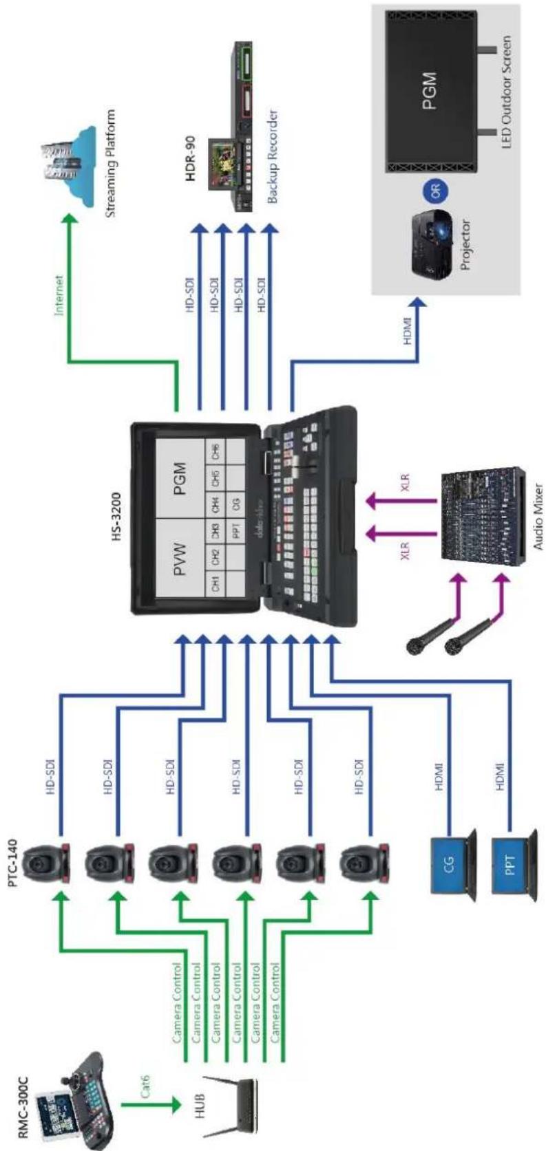
flowchart
graph TD
    A["RMC-300C"] -->|Cat6| B["HUB"]
    B --> C["PTC-140"]
    C --> D["HD-SDI"]
    C --> E["HD-SDI"]
    C --> F["HD-SDI"]
    C --> G["HD-SDI"]
    C --> H["HD-SDI"]
    C --> I["HD-SDI"]
    C --> J["HD-SDI"]
    C --> K["HD-SDI"]
    L["CG"] --> M["HDMI"]
    N["PPT"] --> O["HDMI"]
    P["Audio Mixer"] --> Q["XLR"]
    P --> R["XLR"]
    S["Internet"] --> T["Streaming Platform"]
    U["Hybrid System"] --> V["Data Receiver"]
    W["Projector"] --> X["Projection"]
    Y["LED Outdoor Screen"] --> Z["PGM"]
    style A fill:#f9f,stroke:#333
    style B fill:#ccf,stroke:#333
    style C fill:#cfc,stroke:#333
    style D fill:#fcc,stroke:#333
    style E fill:#fcc,stroke:#333
    style F fill:#fcc,stroke:#333
    style G fill:#fcc,stroke:#333
    style H fill:#fcc,stroke:#333
    style I fill:#fcc,stroke:#333
    style J fill:#fcc,stroke:#333
    style K fill:#fcc,stroke:#333
    style L fill:#fcc,stroke:#333
    style M fill:#cff,stroke:#333
    style N fill:#cff,stroke:#333
    style O fill:#cff,stroke:#333
    style P fill:#ffc,stroke:#333
    style Q fill:#ffc,stroke:#333
    style R fill:#ffc,stroke:#333
    style S fill:#ffc,stroke:#333
    style T fill:#ffc,stroke:#333
    style U fill:#ffc,stroke:#333
    style V fill:#ffc,stroke:#333
    style W fill:#ffc,stroke:#333
    style X fill:#ffc,stroke:#333
2. Connections and Controls
This section provides an introductory overview of the device functions on front and rear panels.
2.1 With Headphone Monitoring
Front Panel


Power On / Off Button
Push once to switch the HDR-90 ON.
Push and hold for at least 6 seconds to switch the HDR-90 OFF.
flowchart
graph TD
    A["I"] --> B["Circle"]
    B --> C["Loop"]
    style A fill:#f9f,stroke:#333
    style B fill:#bbf,stroke:#333
    style C fill:#dfd,stroke:#333
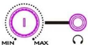
Headphone Audio Monitoring
Stereo mini jack plug for stereo headphone. The headphone audio level is controlled by the volume knob.

Menu Button
This calls up the menu display on the touch screen. For more about using the menu, see MENU.

CLIP Button
Press the "CLIP" button to enable clip management on the touch screen. For more about clip management, see CLIP.
SEL DRIVE
The SEL DRIVE button selects the drive that you would like to record to. For more about drive installation, see SSD Slots.
Stop Button
Press to stop playback or record.
Play / Pause Button
Press to play or pause playback. The status will be displayed on the 5"Touch Screen. For more about video playback, see Dashboard.

Record Button
To start recording, press the Record button then the Play/Pause button. The status including the time code as well as the remaining recordable time will be displayed on the 5"Touch Screen. For more about video recording, see Dashboard.
Note: HDR-90 will not record if no video signal is present.

Rew Button
In playback state, press this button to Fast Rewind.
Fwd Button
In playback state, press this button to Fast Forward.
USB Port
Reserved for future development.
SD CARD SLOT
SD Card Slot
Reserved for future development.
Rear Panel

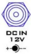
DC IN Socket
Connects the supplied 12V PSU to this socket. The connection can be secured by screwing the outer fastening ring of the DC In plug to the socket.
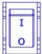
Power On / Off Button
Press to switch the HDR-90 ON/OFF.

Grounding Terminal
When connecting this unit to any other component, make sure that it is properly grounded by connecting this terminal to an appropriate point. When connecting, use the socket and be sure to use wire with a cross-sectional area of at least 1.0 mm^2 .
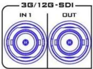
3G\*/12G\*\*-SDI Input and Output
Allow input and output of 3G/12G-SDI videos through the respective 3G/12G SDI interfaces.
Note 1: The device will NOT record if there is no video reference connected to input channel 1 so please make sure a video source is always connected to input channel 1 even in iso recording mode.
Note 2: All input video formats must be the same and the device must be power cycled when a different video format is connected to input channel 1.
Note 3: Only 48 kHz embedded audio is supported. Up to 8 embedded audio channels can be recorded across all input channels. An extra external XLR audio can be recorded to input channel 1 only.
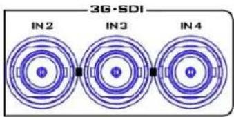
3G\*-SDI Inputs
Connect 3G-SDI video sources through three 3G SDI interfaces.
Note: Input channels 2 – 4 will be disabled upon connection of a 4K video source to input channel 1.
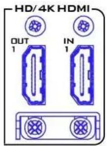
HD/4K-HDIM Input and Output
Allow input and output of HD/4K videos through the respective HDMI interfaces.
Note 1: The device will NOT record if there is no video reference connected to input channel 1 so please make sure a video source is always connected to input channel 1 even in iso recording mode.
Note 2: All input video formats must be the same and the device must be power cycled when a different video format is connected to input channel 1.
Note 3: Only 48 kHz embedded audio is supported. Up to 8 embedded audio channels can be recorded across all input channels. An extra external XLR audio can be recorded to input channel 1 only.
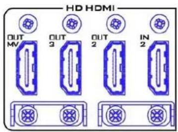
HD-HDMI Outputs
Connect external HDMI devices for playback of HD videos.
OUT MV: The Multiview output port displays a quad view on the connected monitor.
OUT 2/3: The output ports display Program view on the connected monitor.
IN 2: Connect a video source to the input port.
Note: Upon connection of a 4K video source, the built-in 5" LCD monitor and the OUT MV will display a single view only. The 4K video format will only be retained at the HDMI OUT 1 port and downgraded to 1080p at the rest of the output ports.
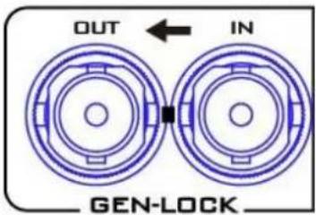
Genlock IN / OUT
Use Black Burst or Tri-Level Mode as video reference when synchronizing other devices to the HDR-90.
Note: User needs to add a 75 ohm terminator if this is the last device of the Black Burst signal chain.
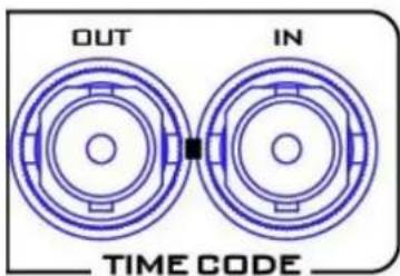
Time Code Signal IN /OUT
The user can select the time code source as internal or external. Set time code source to external when supplying an external Time Code source to this input port.
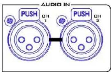
XLR Analog Audio IN
XLR IN Port for balanced audio connection.
Note: HDR-90 is equipped with ISO recording which gives you the ability to create isolated recordings of camera inputs. HDR-90 allows connection of up to four 1080p video sources. During ISO recording, the audio source connected to the XLR analog audio IN will ONLY be recorded to video channel 1 when multiple input channels are connected of 1080p video sources.
See XLR Setup for XLR Analog Audio IN settings.
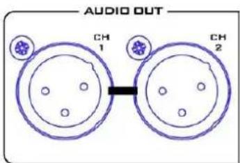
XLR Analog Audio OUT
XLR OUT Port for audio channel 1/2 outputs and the volume is controlled by the volume knob on the front panel.
See XLR Setup for XLR Analog Audio IN settings.
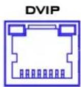
Ethernet Port
TBD

GPI
GPI Control
The GPI socket can be used for simple external control.
The recorder can accept pulse or level trigger inputs, which can trigger record or playback and pause commands.

RS-232/ RS-422
RS-232/422 Remote Control
TBD
*The 3G-SDI is known as the 3 Gb/s interface, but the actual bit rates are 2.97 Gb / s and 2.97 / 1.001 Gb / s. 3G-SDI supports several different mapping levels, as described in the SMPTE ST425-1 standard. These levels are called A, B-DL, and B-DS.
**The 12G-SDI is an SDI standard developed to support higher resolution, frame rate, and color fidelity. It provides four times the bandwidth of HD, carrying 12Gbps, making it ideal for the 4K 60p format.
2.2 Without Headphone Monitoring
Front Panel

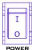
Power On / Off Button
Press to switch the HDR-90 ON/OFF.

Menu Button
This calls up the menu display on the touch screen. For more about using the menu, see MENU.

CLIP Button
Press the "CLIP" button to enable clip management on the touch screen. For more about clip management, see CLIP.

SEL DRIVE
The SEL DRIVE button selects the drive that you would like to record to. For more about drive installation, see SSD Slots.

Stop Button
Press to stop playback or record.

Play / Pause Button
Press to play or pause playback. The status will be displayed on the 5"Touch Screen. For more about video playback, see Dashboard.

Record Button
To start recording, press the Record button then the Play/Pause button. The status including the time code as well as the remaining recordable time will be displayed on the 5"Touch Screen. For more about video recording, see Dashboard.
Note: HDR-90 will not record if no video signal is present.

Rew Button
In playback state, press this button to Fast Rewind.

Fwd Button
In playback state, press this button to Fast Forward.
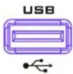
USB Port
Reserved for future development.
SD CARD SLOT

SD Card Slot
Reserved for future development.
Rear Panel

DC IN 12V

DC IN Socket
Connects the supplied 12V PSU to this socket. The connection can be secured by screwing the outer fastening ring of the DC In plug to the socket.

Grounding Terminal
When connecting this unit to any other component, make sure that it is properly grounded by connecting this terminal to an appropriate point. When connecting, use the socket and be sure to use wire with a cross-sectional area of at least 1.0 mm^2 .
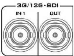
3G\*/12G\*\*-SDI Input and Output
Allow input and output of 3G/12G-SDI videos through the respective 3G/12G SDI interfaces.
Note 1: The device will NOT record if there is no video reference connected to input channel 1 so please make sure a video source is always connected to input channel 1 even in iso recording mode.
Note 2: All input video formats must be the same and the device must be power cycled when a different video format is connected to input channel 1.
Note 3: Only 48 kHz embedded audio is supported. Up to 8 embedded audio channels can be recorded across all input channels. An extra external XLR audio can be recorded to input channel 1 only.
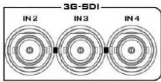
3G\*-SDI Inputs
Connect 3G-SDI video sources through three 3G SDI interfaces.
Note: Input channels 2 – 4 will be disabled upon connection of a 4K video source to input channel 1.
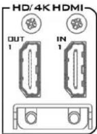
HD/4K-HDIM Input and Output
Allow input and output of HD/4K videos through the respective HDMI interfaces.
Note 1: The device will NOT record if there is no video reference connected to input channel 1 so please make sure a video source is always connected to input channel 1 even in iso recording mode.
Note 2: All input video formats must be the same and the device must be power cycled when a different video format is connected to input channel 1.
Note 3: Only 48 kHz embedded audio is supported. Up to 8 embedded audio channels can be recorded across all input channels. An extra external XLR audio can be recorded to input channel 1 only.
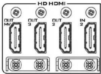
HD-HDMI Outputs
Connect external HDMI devices for playback of HD videos. OUT MV: The Multiview output port displays a quad view on the connected monitor.
OUT 2/3: The output ports display Program view on the connected monitor.
IN 2: Connect a video source to the input port.
Note: Upon connection of a 4K video source, the built-in 5" LCD monitor and the OUT MV will display a single view only. The 4K video format will only be retained at the HDMI OUT 1 port and downgraded to 1080p at the rest of the output ports.
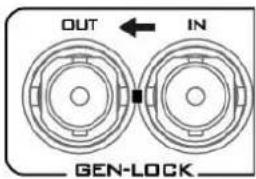
Genlock IN / OUT
Use Black Burst or Tri-Level Mode as video reference when synchronizing other devices to the HDR-90.
Note: User needs to add a 75 ohm terminator if this is the last device of the Black Burst signal chain.
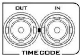
Time Code Signal IN /OUT
The user can select the time code source as internal or external. Set time code source to external when supplying an external Time Code source to this input port.
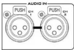
XLR Analog Audio IN
XLR IN Port for balanced audio connection.
Note: HDR-90 is equipped with ISO recording which gives you the ability to create isolated recordings of camera inputs. HDR-90 allows connection of up to four 1080p video sources. During ISO recording, the audio source connected to the XLR analog audio IN will ONLY be recorded to video channel 1 when multiple input channels are connected of 1080p video sources.
See XLR Setup for XLR Analog Audio IN settings.
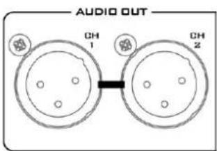
XLR Analog Audio OUT
XLR OUT Port for audio channel 1/2 outputs and the volume is controlled by the volume knob on the front panel.
See XLR Setup for XLR Analog Audio IN settings.
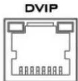
Ethernet Port
TBD

GPI
GPI Control
The GPI socket can be used for simple external control. The recorder can accept pulse or level trigger inputs, which can trigger record or playback and pause commands.

RS-232/ RS-422
RS-232/422 Remote Control
TBD
*The 3G-SDI is known as the 3 Gb/s interface, but the actual bit rates are 2.97 Gb / s and 2.97 / 1.001 Gb / s. 3G-SDI supports several different mapping levels, as described in the SMPTE ST425-1 standard. These levels are called A, B-DL, and B-DS.
**The 12G-SDI is an SDI standard developed to support higher resolution, frame rate, and color fidelity. It provides four times the bandwidth of HD, carrying 12Gbps, making it ideal for the 4K 60p format.
3. SSD Slots
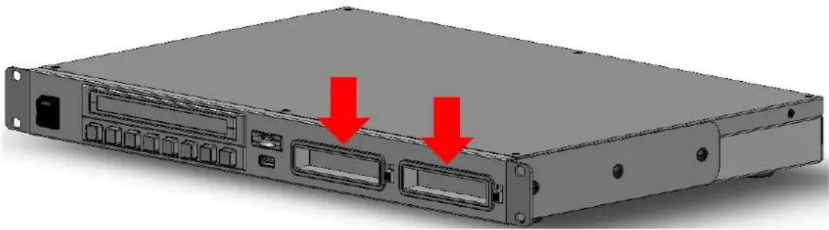
The SSD slots are located on the front panel.
natural_image
Front view of a server rack with two red arrows pointing to ports (no text or symbols visible)The SSD must be installed in a removable disk enclosure (see Install an SSD drive in a Removable Disk Enclosure) before inserting into SSD slots. After disk insertion, make sure the drive is locked to avoid unintentional disk removal. Move the latch to the LOCK position. To remove the disk, unlock the drive then pull the disk out of the slot.
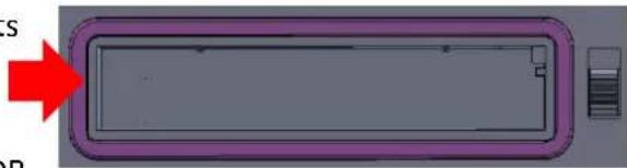
The slot LED indicators show disk status of SSD slots 1 and 2 respectively. With the disk inserted, solid green light indicates that the disk is ready and functioning; flashing red light indicates that the HDR
natural_image
Diagram of a rectangular device with purple border and gray interior, no visible text or symbolsunit is accessing the disk (do not remove the disk while it is being accessed). The LED will be off if no disk is inserted or detected.
Note: HDR-90 only accepts Samsung 860 Pro SSD and 870 EVO SSD only.
3.1 Install an SSD in a Removable Disk Enclosure
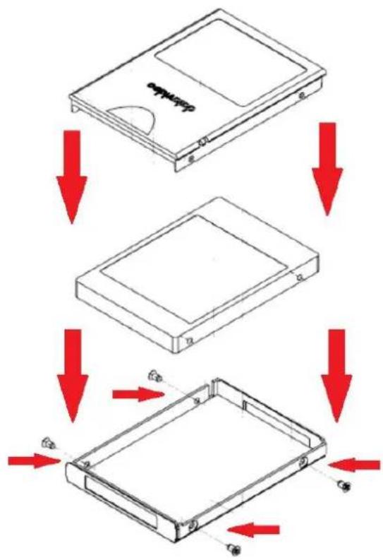
If your unit was delivered without a hard drive inserted, please follow the steps below to insert the hard disk into a drive enclosure before inserting into the HDR.
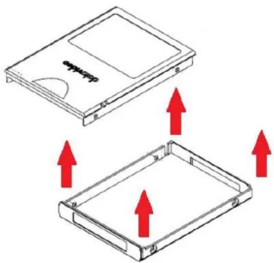
- Remove the four screws on two sides of the SSD disk enclosure then lift the top plate.
flowchart
graph TD
    A["Device Package"] --> B["Step 1"]
    B --> C["Step 2"]
    C --> D["Step 3"]
    D --> E["Final Box with Red Arrow indicating directional movement"]
- As shown in the diagram on the left, place an SSD in the drive enclosure then re-secure the top plate of the drive enclosure using the four screws removed earlier.
natural_image
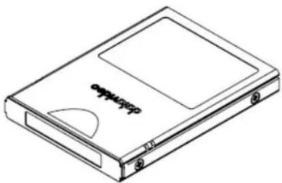
Line drawing of a rectangular electronic device with a label 'SHEVATE' on the front panel (no other text or symbols)- Completion of disk drive enclosure assembly.
natural_image
Diagram of a device casing with a highlighted internal component and a red circle highlighting it (no text or symbols present)-
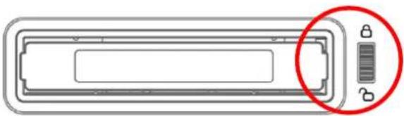
Push the drive enclosure into recorder as shown. Now move the locking latch from bottom to the top to secure the drive enclosure in place.
-
Switch ON the unit.
-
New drives will be formatted within the recorder upon first use. The status will displayed on the touch screen and will prompt the user as soon as the recorder becomes available for setup and use.
Notes:
- Do not delete recorded files from any folders on the SSD as this may lead to file access errors.
- When recording on the same SSD, it is highly recommended to use one video format only.
- In case of any unexpected power off, the last recorded video clip will be still stored on the SSD but you might lose the last 3-5 second video frames. To resume recording, remove the SSD drive, turn on the device then insert the SDD back into the slot.
- It is highly recommended to at least low level format the disk before use. See Format SSD.
- When recording to two SSDs simultaneously, do not pull out either SSD while the recording is in progress as this may force the device to stop recording.
4. Human Machine Interface
The built-in 5 inch touch screen allows you to configure the record and system settings. In addition, the user can view saved clips and live video directly on the touch screen.
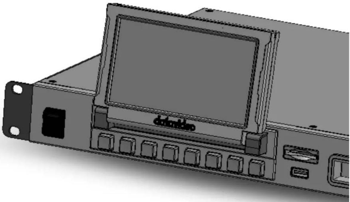
natural_image
Illustration of a server rack unit with a monitor and ports, no visible text or symbolsFirst make sure the SSD is inserted; see SSD Slots for instructions if you have not already done so. As the machine boots, you should see the boot-up screen as shown below.
4.1 Dashboard
After the system boot-up is finished, the main screen will be displayed as shown below.
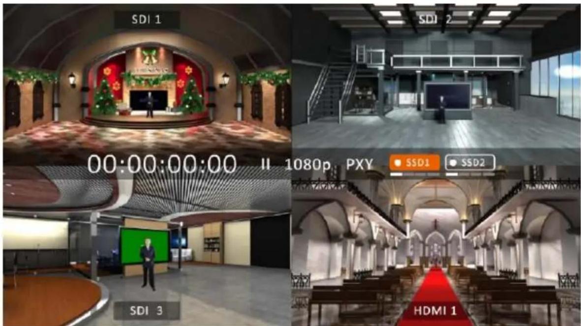
Push the Record button then the Play/Pause button to activate the record function. You should see the record status on the quad split screen as shown below.
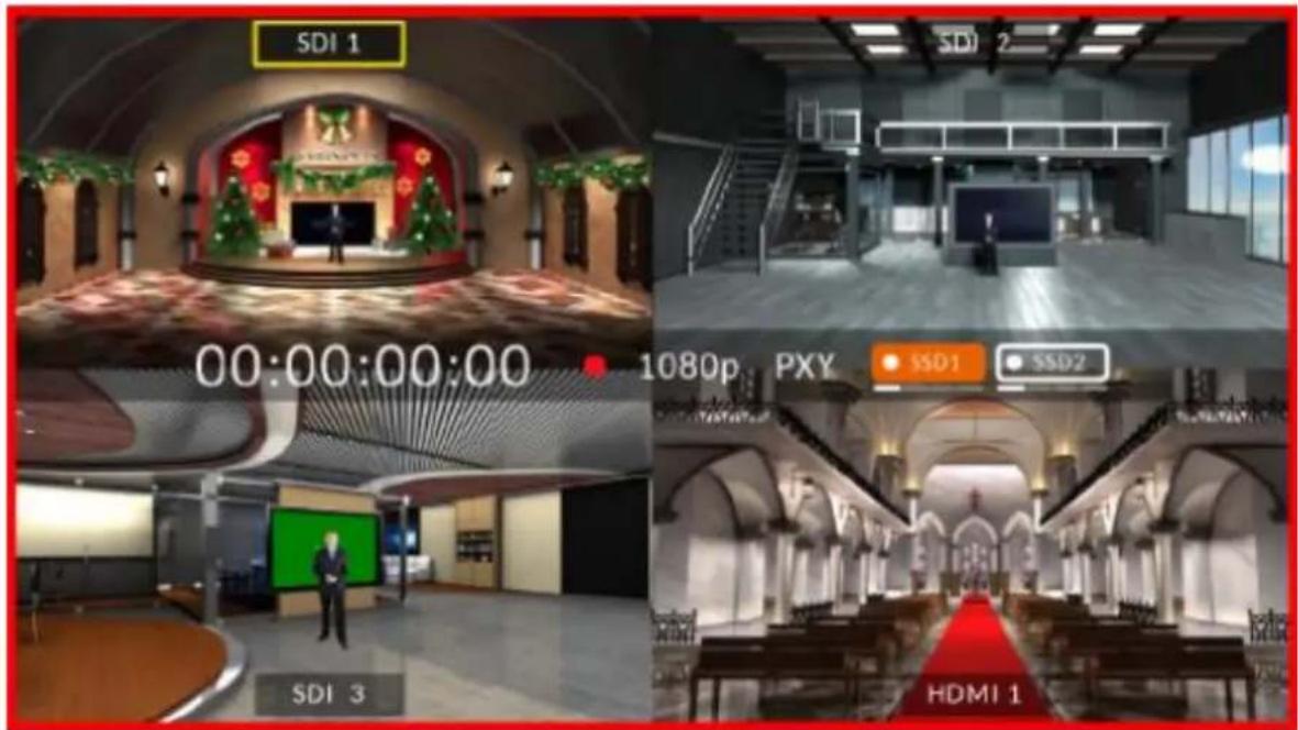
On the quad split screen, tap one of the screens to switch between HDMI and SDI video sources.
To enter the full screen mode as shown below, tap the video source name.
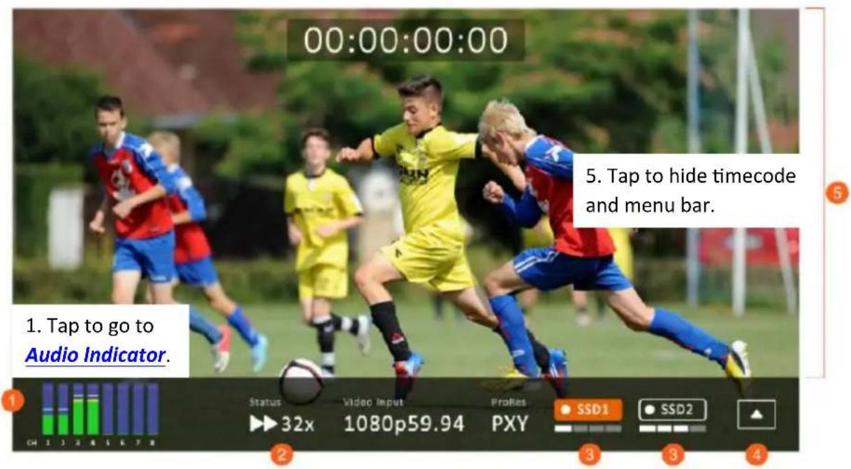
- Tap to set the Play Speed.
- Tap to select the disk drive or show Disk Information.
- Tap to show Sub-Menu.
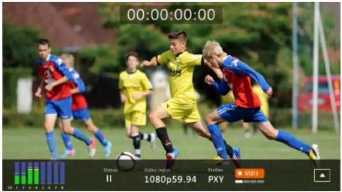
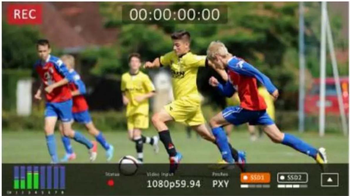
In the full screen mode, you can either press the Play/Pause button to play the record clip or press the Record button → Play/Pause button to start recording.
Play State
Record State
You will see the following prompt if RECORD fails.
See notes about SSD Slots for possible record failure causes.
RECORD FAIL. PLEASE PRESS STOP KEY
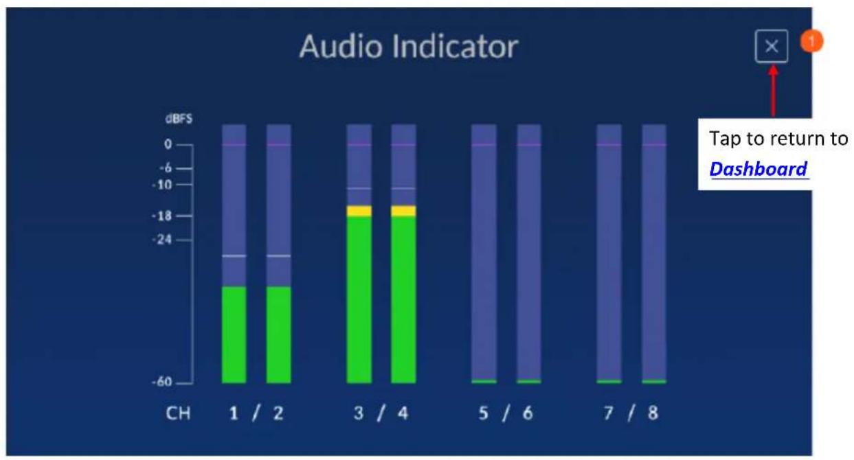
4.1.1 Audio Indicator
The respective channel audio indicators are shown below.
bar_stacked
| Category | Green Segment (dBFS) | Blue Segment (dBFS) | | -------- | -------------------- | ------------------- | | CH | -30 | -20 | | 1 | -30 | -15 | | / | -30 | -15 | | 2 | -30 | -15 | | 3 | -18 | -8 | | / | -18 | -8 | | 4 | -18 | -8 | | 5 | -6 | -20 | | / | -6 | -20 | | 6 | -6 | -20 | | 7 | -6 | -20 | | / | -6 | -20 | | 8 | -6 | -20 |4.1.2 Play Speed
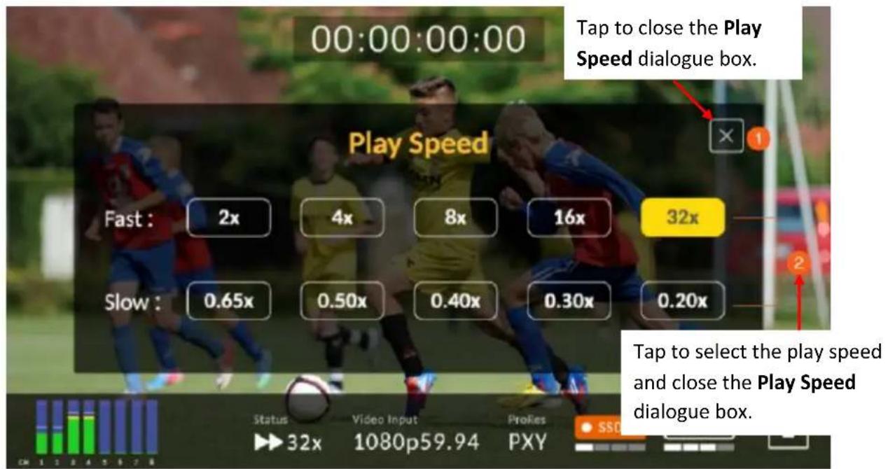
4.1.3 Disk Information
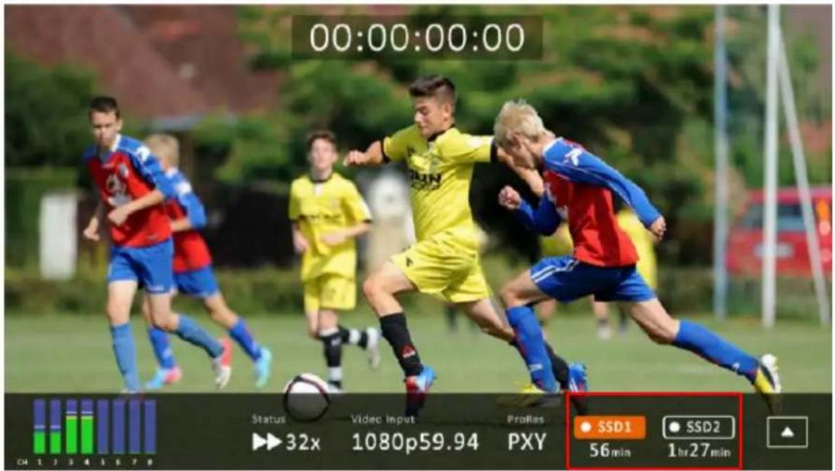
Tap SSD1 icon to display remaining recordable time and disk information. An example of the disk information is shown below.
| SSD 1 | SSD 2 | ||
| Total: | 953 GB | Total: | 953 GB |
| Free: | 880 GB | Free: | 953 GB |
| Available: | 2hr4min | Available: | 2hr15min |
Note: If only SSD2 slot contains the hard disk, then the disk information will not be displayed.
4.1.4 Sub-Menu
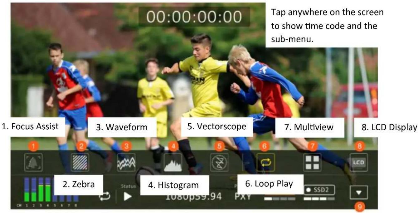
- Tap to hide timecode and menu bar.
Focus Assist
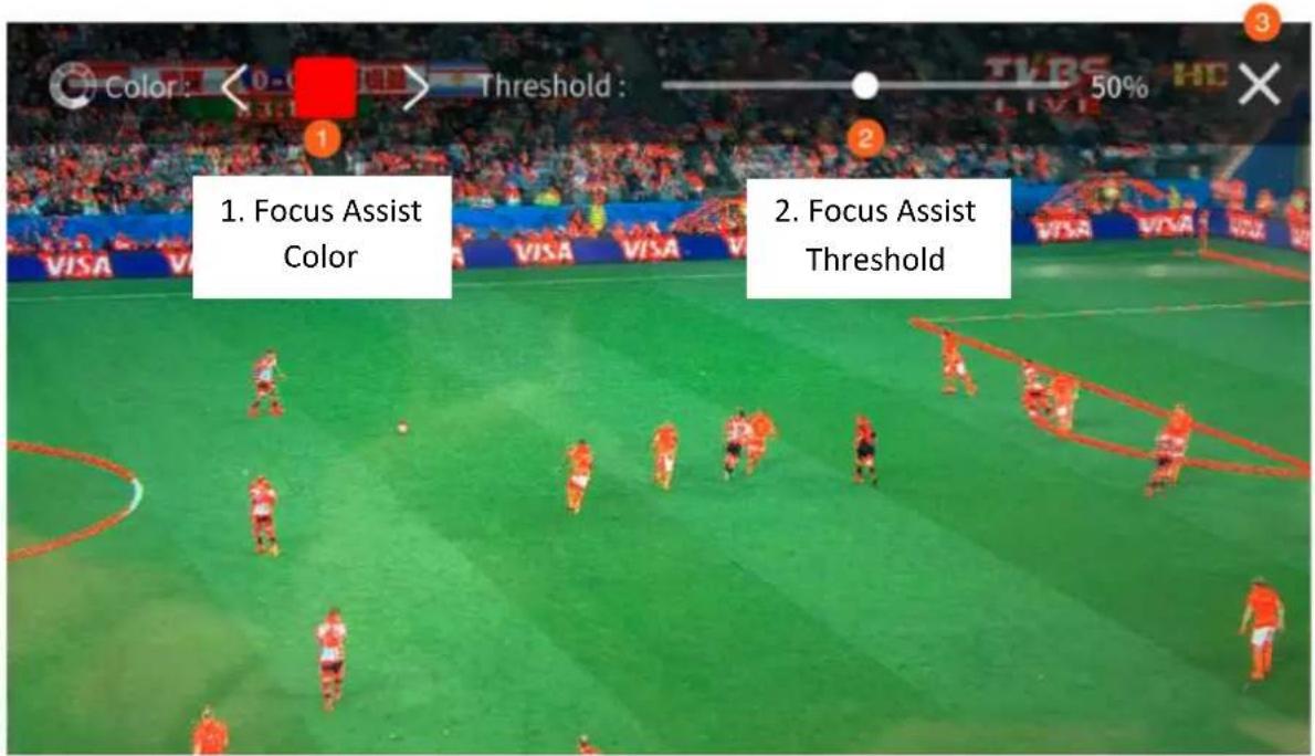
Enabling the Focus Assist enables the peaking filter which places color lines on edges of the subject of the focus in the image.
The Focus Assist Level determines the sensitivity of the filter. Setting the level to a high value means more areas will be highlighted including lower contrast areas. If the level is set to a low value, then only areas of high contrast will be highlighted.
The diagram below illustrates images with peaking filter applied to the subject of the focus. Note the red color of the outlines in each picture.
- Tap to close
Zebra
Once the zebra function is turned ON, you will be able to see a zebra pattern superimposed over parts of the image that are exposed to a specific level.
- Zebra Color
- Tap to close
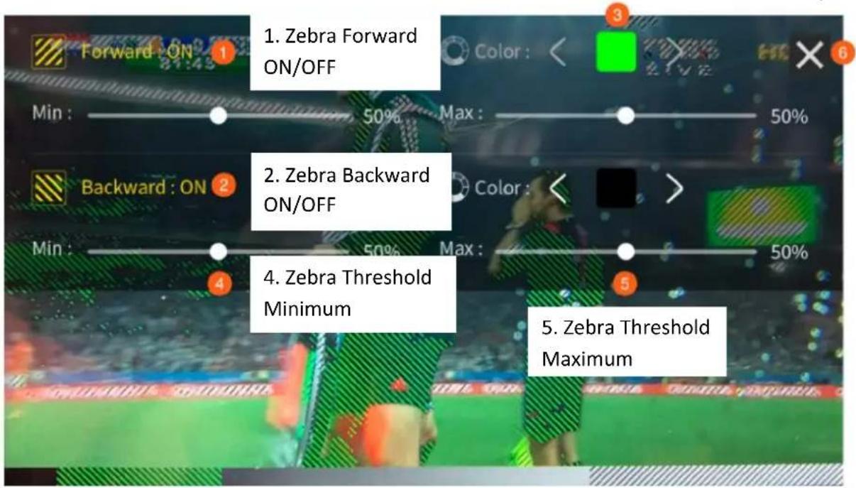
Default forward zebra pattern: Green
Default backward zebra pattern: Black
Waveform
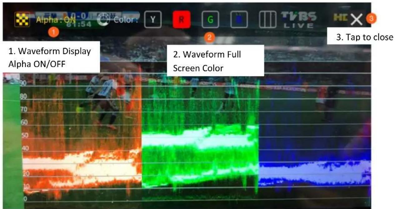
Waveform monitoring consists of RGB and YCbCr waveforms which are used to measure the brightness, luminance and chroma of a video signal as shown in the diagram below.
Histogram
The RGB histogram is a great tool that helps you identify the image's overall exposure.
In any digital image, each individual color is made by combining red, green and blue lights with each light represented by its brightness level ranging from 0 to 255. Therefore every color produced in this way has a specific brightness value based on mixes of red, green and blue throughout the image and these brightness values of all the different colors in an image are represented in a histogram which is known as the RGB histogram.
Vectorscope
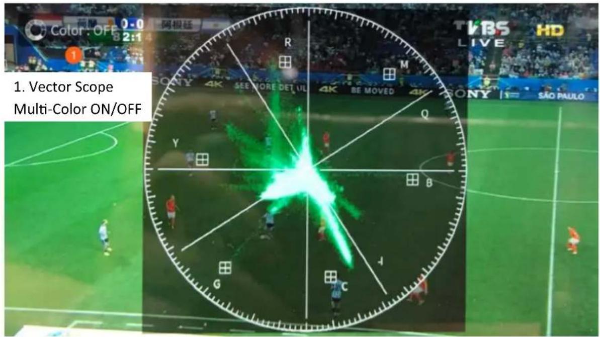
The vectorscope is used to measure the color information such as Hue and Saturation in a video image.
Hue: The color markers are red, magenta, blue, cyan, green, and yellow. The proximity of a signal to one of the markers tells you what color it is.
Saturation: A vectorscope shows you how saturated your color is and how far away the signal is from the center indicates how saturated the color is. For example, if the color is close to one of those boxes, then that means that color in the image is very saturated.
Intersecting lines: The line going up towards the yellow and red colors is the skin tone line on which the skin color should fall regardless of the person's race.
Loop Play
Tap the loop play icon to repeat the current video playback.
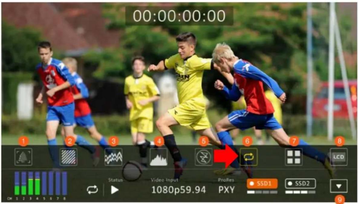

Multiview
Tap the Multiview icon to switch to Multiview Display.
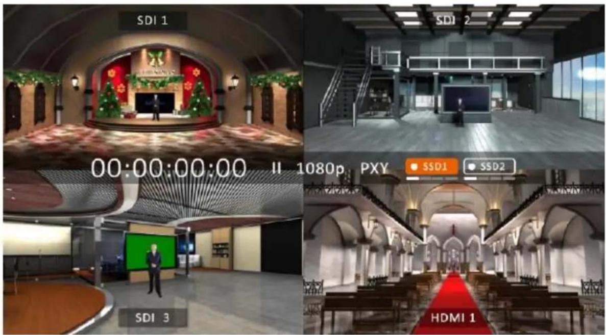
Alternatively, while in the single view mode, you can tap the video source channel label as shown in the diagram below to switch to Multiview Display.
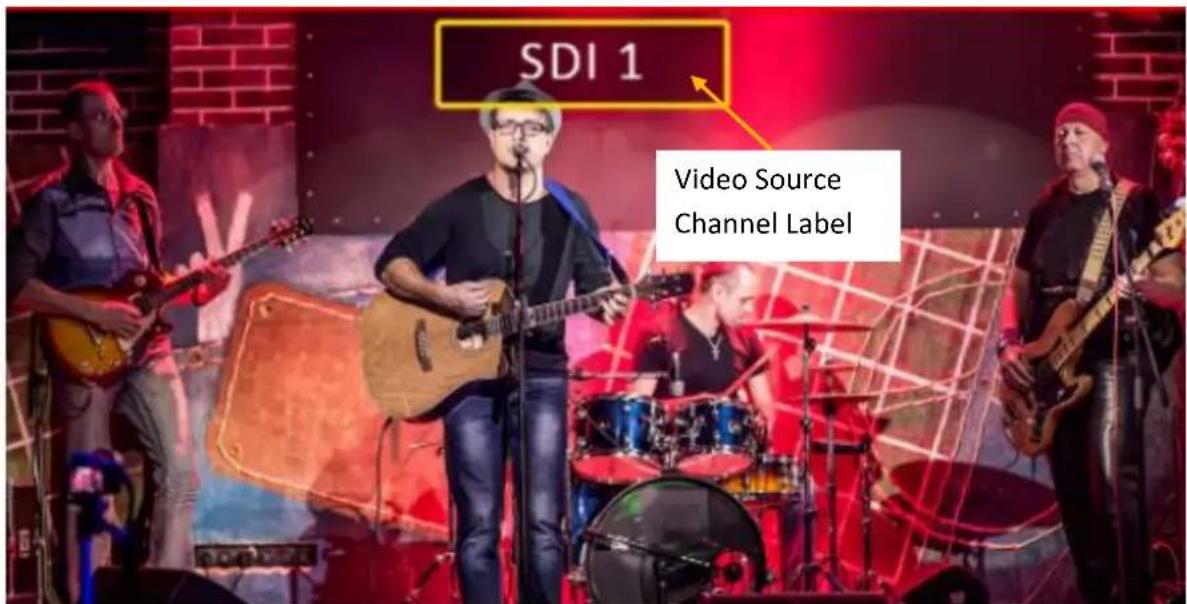
LCD Display
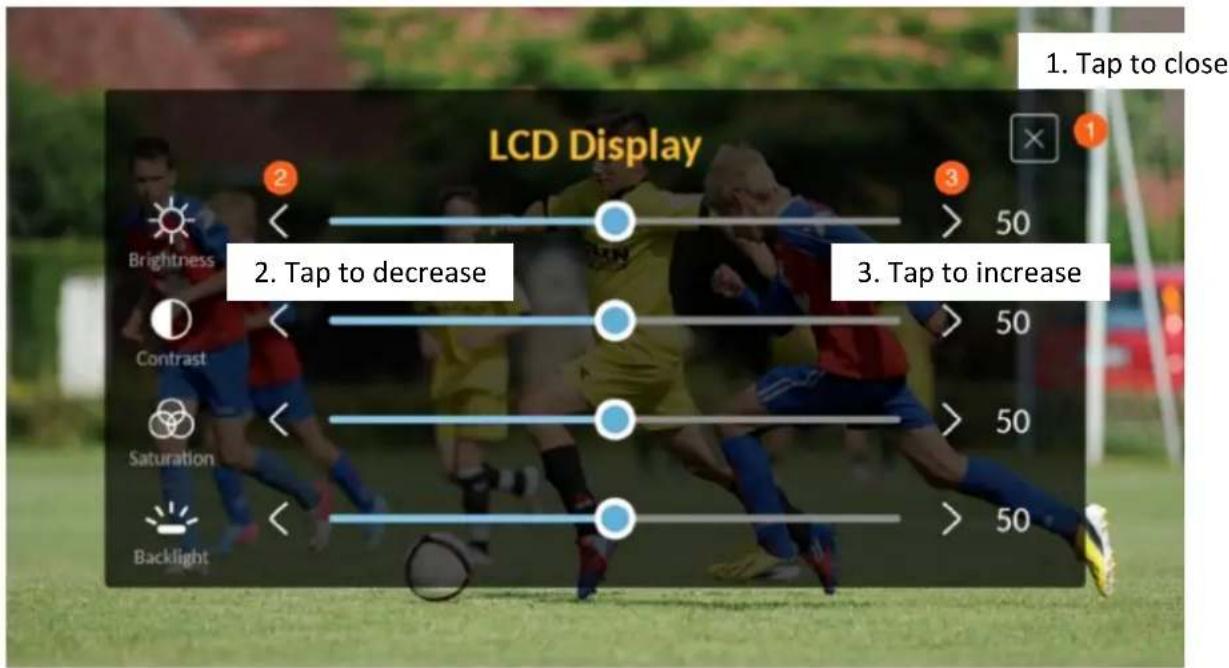
4.2 CLIP
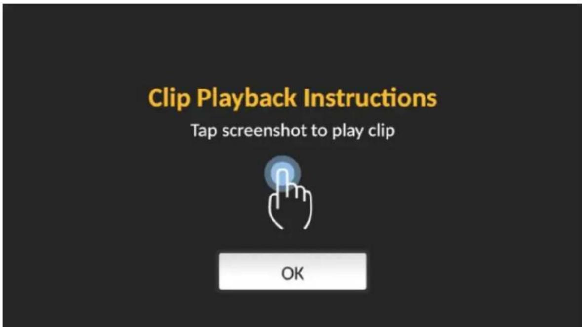
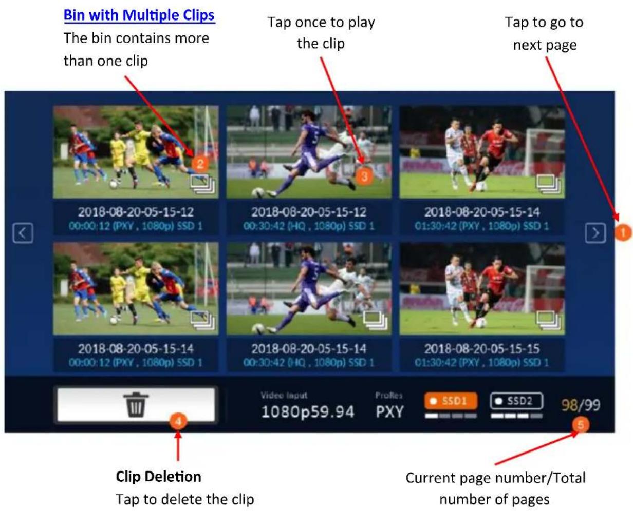
Pressing the CLIP button should bring up the clip management screen on the 5" touch screen as shown below. Tapping OK will take you to the clip thumbnails page.
4.2.1 Bin with Multiple Clips
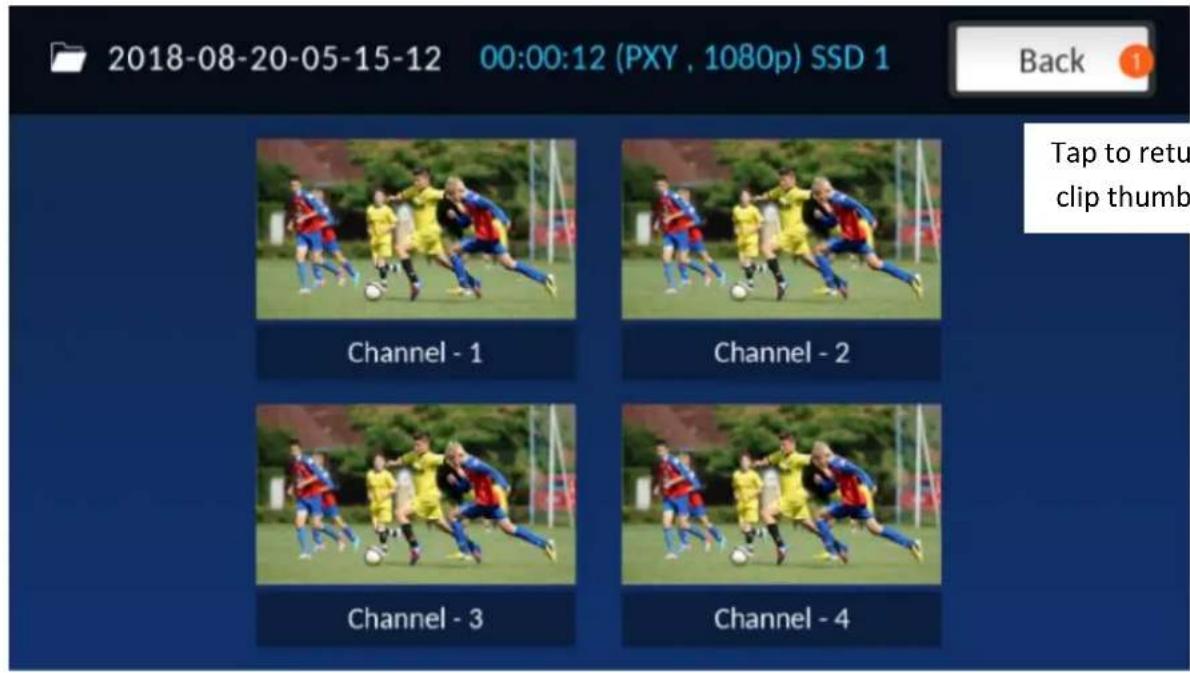
On the screen showing clip thumbnails, after tapping the clip thumbnail that has multiple clips, you should see the following screen. Double tap one of them to play the clip.
4.2.2 Single Clip Deletion
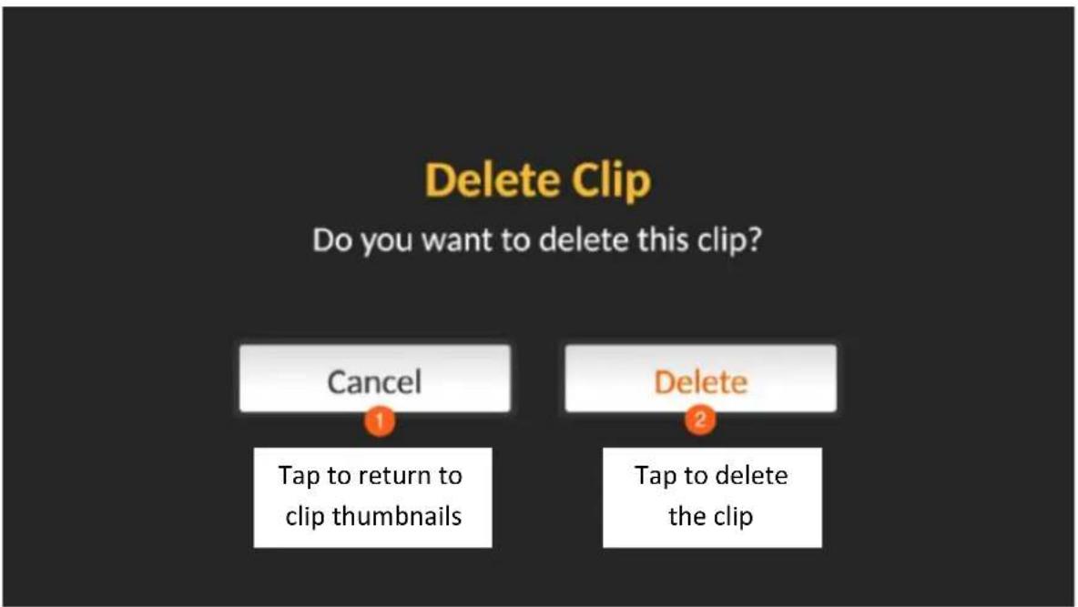
To delete a particular clip on the screen showing clip thumbnails, first tap one of the clip thumbnails then tap the Delete button. When you see the screen below, tap "Delete" to confirm the deletion and "Cancel" to return to the clip thumbnail screen.
Note: Deletion of a single clip file should not take more than 10 seconds. It should take more than one minute to delete multiple clip files.
4.2.3 Multiple Clip Deletion
On the clip thumbnail screen, tap and hold until the screen below appears then select the clips that you would like to delete. You can also tap the "Select ALL" button to select all six clip files. Tap the Delete button to delete the selected clip(s).
Note: The "Select All" button selects all the clip files shown on the current page only.
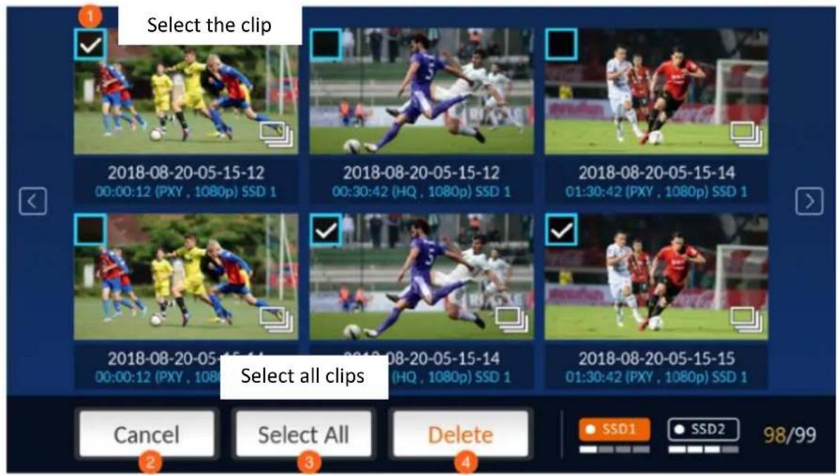
Cancel to return to previous screen
Delete selected clips
4.3 MENU
Pressing the MENU button should bring up the menu screen on the human machine interface as shown below.
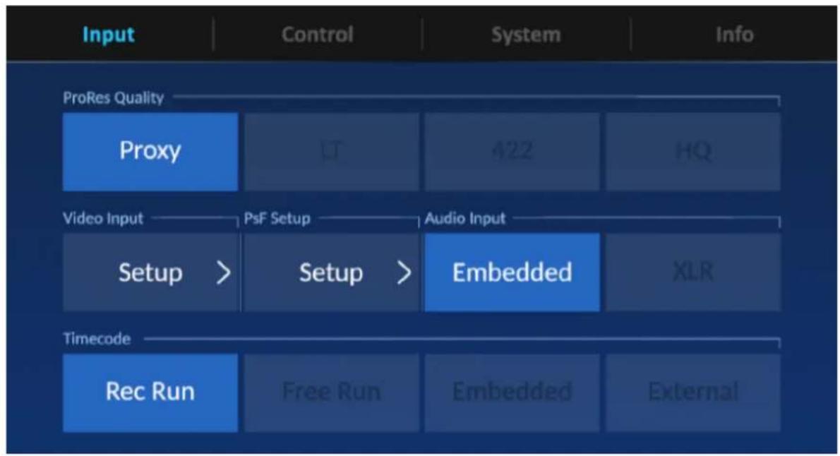
flowchart
graph TD
    A["Input"] --> B["ProRes Quality"]
    B --> C["Proxy"]
    C --> D["LT"]
    D --> E["422"]
    E --> F["HQ"]
    G["Video Input"] --> H["Setup >"]
    H --> I["PsF Setup"]
    I --> J["Audio Input"]
    J --> K["Embedded"]
    K --> L["XLR"]
    M["Timecode"] --> N["Rec Run"]
    N --> O["Free Run"]
    O --> P["Embedded"]
    P --> Q["External"]
4.3.1 Input
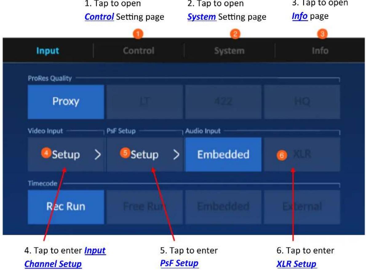
flowchart
graph TD
    A["1. Tap to open Control Setting page"] --> B["2. Tap to open System Setting page"]
    B --> C["3. Tap to open Info Page"]
    D["ProRes Quality Proxy"] --> E["4 Setup >"]
    F["Video Input"] --> G["Timecode Rec Run"] --> H["5 Setup >"]
    I["Audio Input"] --> J["6 Embedded"]
    K["4. Tap to enter Input Channel Setup"] --> L["5. Tap to enter PsF Setup"]
    M["6. Tap to enter XLR Setup"] --> N["External"]
ProRes Quality
Select the ProRes quality that meets the requirement of your application. The options are described below.
HQ 4:2:2
A higher-data-rate version of ProRes 422 that preserves visual quality at the same high level as ProRes 4444, but for 4:2:2 image sources. With widespread adoption across the video post-production industry, ProRes 422 HQ offers visually lossless preservation of the highest-quality professional HD video that a single-link HD-SDI signal can carry. This codec supports full-width, 4:2:2 video sources at 10-bit pixel depths, while remaining visually lossless through many generations of decoding and re-encoding. The target data rate of ProRes 422 HQ is approximately 220 Mbps at 1920 x 1080 and 29.97 fps.
Standard 4:2:2
A high-quality compressed codec offering nearly all the benefits of ProRes 422 HQ, but at 66 percent of the data rate for even better multistream, real-time editing performance. The target data rate of ProRes 422 is approximately 147 Mbps at 1920 x 1080 and 29.97 fps.
LT 4:2:2
A more highly compressed codec than Apple ProRes 422 Standard, with roughly 70 percent of the data rate and 30 percent smaller file sizes. This codec is perfect for environments where storage capacity and data rate are at a premium. The target data rate of Apple ProRes 422 LT is approximately 102 Mbps at 1920 x 1080 and 29.97 fps.
Proxy 4:2:2
An even more highly compressed codec than ProRes 422 LT, intended for use in offline workflows that require low data rates but full-resolution video. The target data rate of ProRes 422 Proxy is approximately 45 Mbps at 1920 x 1080 and 29.97 fps.
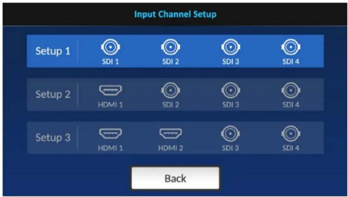
Input Channel Setup
Tap one input channel setup to select an input combination. Also make sure that input channel 1 has been connected of a video source. If input channel 1 is left unconnected, you might experience a black screen or incorrect display on the built-in LCD touch screen.
Note: The Record function will fail if video reference is not connected to input channel 1.
PsF Setup
Select a recording format on this page.
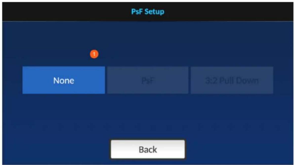
Select None if you want to record a 1080i video source in 1080i format.
PsF stands for Progressive segmented Frame, which allows you to record a 1080i60 video source in 1080p30 format. Also enable PsF if you are recording a PsF video source.
3:2 Pull Down allows you to record a 1080i59.94 video source in 1080p23.97 format.
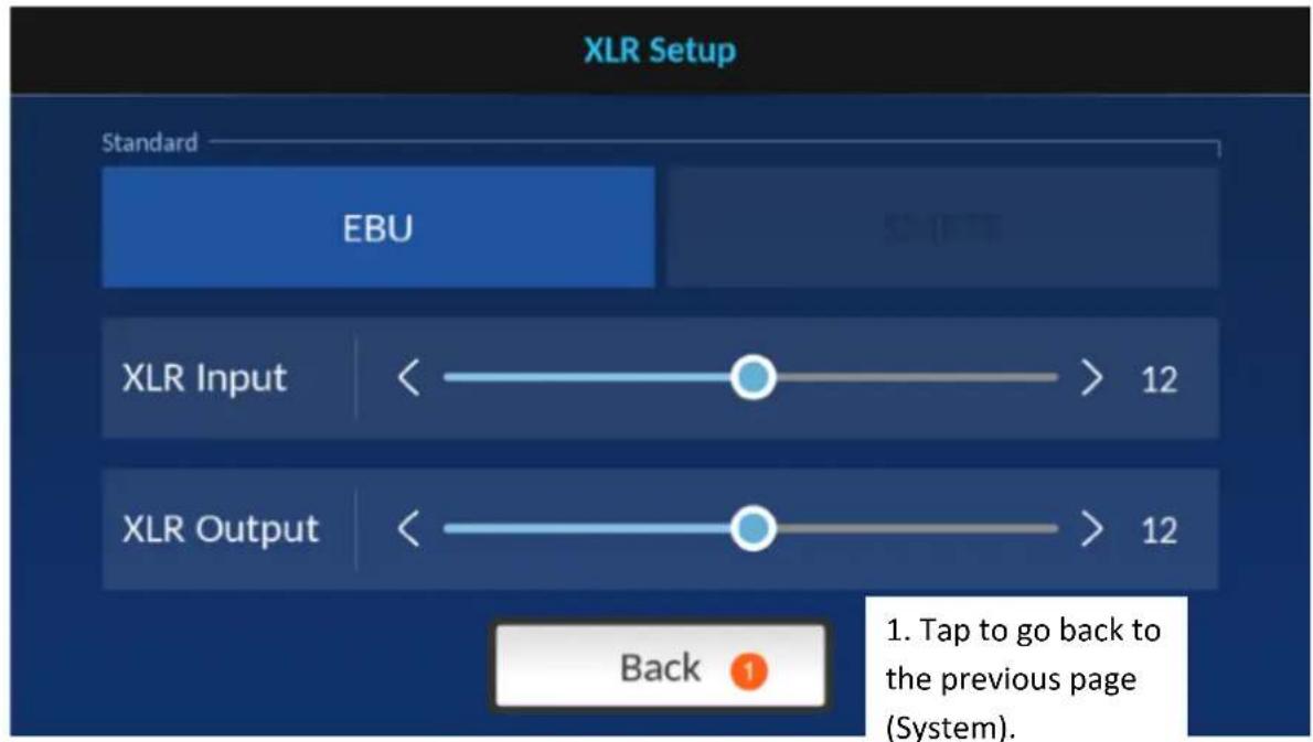
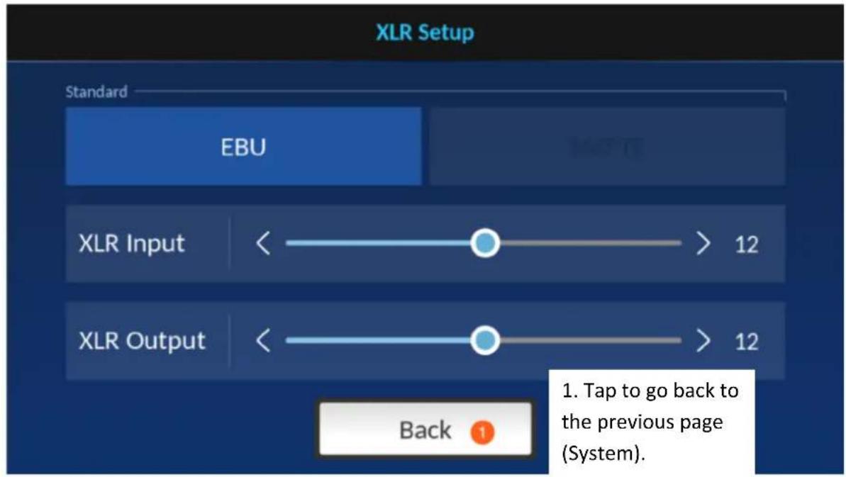
XLR Setup
The XLR Setup page allows you to select the audio format and set the audio level for XLR input/output.
Time Code

flowchart
graph LR
    A["Rec Run"] --> B["Free Run"]
    B --> C["Embedded"]
    C --> D["External"]
Various time code options are described as follows:
• Rec Run: Time code runs during video recording.
• Free Run: Time code runs automatically.
- Embedded: Video embedded time code
• External: Linear (or Longitudinal) Timecode (LTC)
4.3.2 Control
- Tap to open Input
Setting page
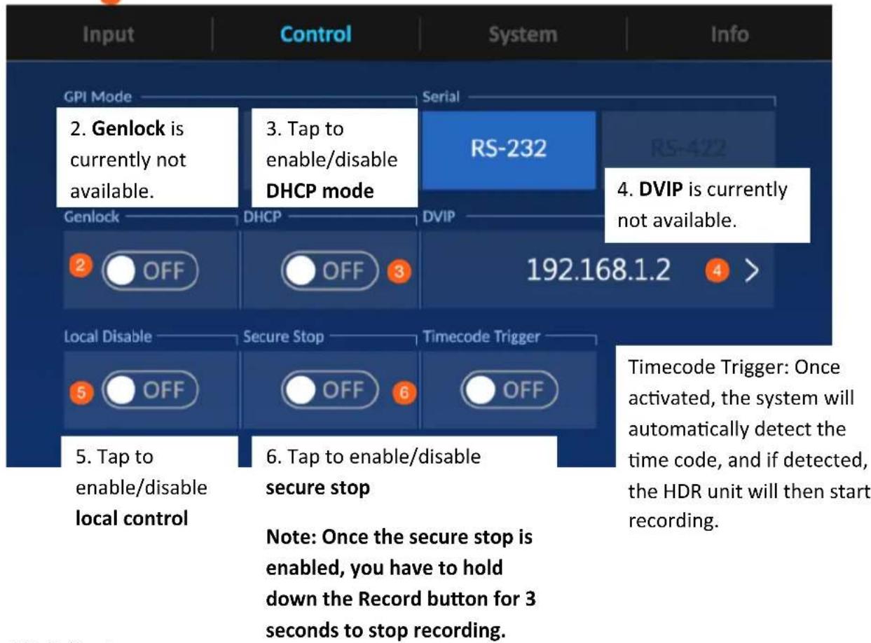
flowchart
graph TD
    A["Input"] --> B["Control"]
    B --> C["System"]
    C --> D["Info"]

    subgraph GPI Mode
        E["2. Genlock is currently not available."] --> F["3. Tap to enable/disable DHCP mode"]
        G["Genlock"] --> H["2 OFF"]
        I["DHCP"] --> J["OFF 3"]
        K["DVIP"] --> L["RS-232"]
        M["Local Disable"] --> N["5 OFF"]
        O["Secure Stop"] --> P["6 OFF"]
        Q["Timecode Trigger"] --> R["4. DVIP is currently not available."]
    end

    subgraph Timecode Trigger
        S["Once activated, the system will automatically detect the time code, and if detected, the HDR unit will then start recording."] --> T["Note: Once the secure stop is enabled, you have to hold down the Record button for 3 seconds to stop recording."]
    end
4.3.3 System
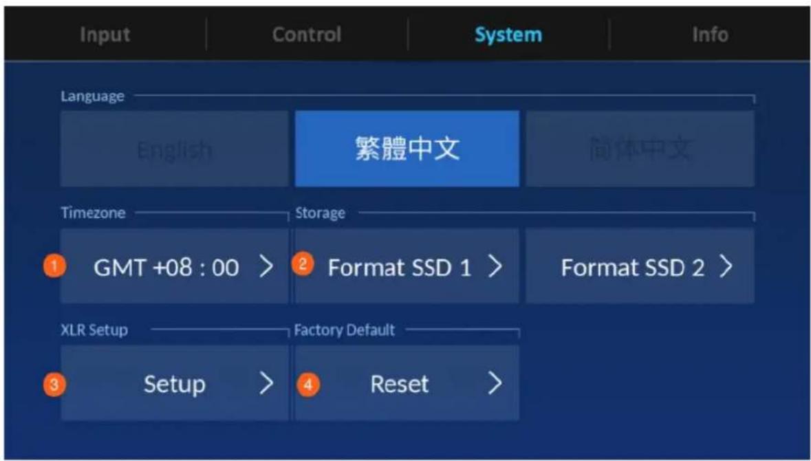
- Tap to enter Time Zone Setting page.
- Tap to format the SSD.
- Tap to enter XLR Setup page.
- Tap to activate factory reset.
Time Zone
![Timezone [GMT +02 : 00] Athína Bucharest Cairo Finland Israel Istanbul Latvia Pretoria 2019-08-09 19:57 1. Tap to move between different time zones. 1. Tap to move between different time zones. Tap to adjust time and Time as own below. Time Setup Save 3. Tap to save and go back to the previous page (System).](/content/2026/05/830673/images/5d0022d66d0f1e218a26eb02d388ccb4a45b135c1c8e508212dc732a9c1a5161.jpg)
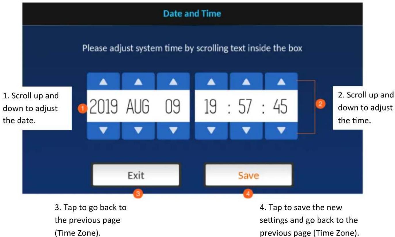
flowchart
graph TD
    A["1. Scroll up and down to adjust the date."] --> B["2019 AUG 09"]
    B --> C["2. Scroll up and down to adjust the time."]
    C --> D["3. Tap to go back to the previous page (Time Zone)."]
    D --> E["4. Tap to save the new settings and go back to the previous page (Time Zone)."]
    E --> F["Exit"]
    E --> G["Save"]
Format SSD
Tap to format the inserted SSD and you will see the prompt shown below.
Format SSD 1
Your SSD 1 content will be deleted.
(This action cannot be undone.)
-
Tap to go back to the previous page (System).
-
Tap to proceed with disk formatting.
Exit
OK


Disk Formatting is in progress.
Format SSD1
Please wait a few minutes...

Once the disk format is complete, you will see the prompt shown below.
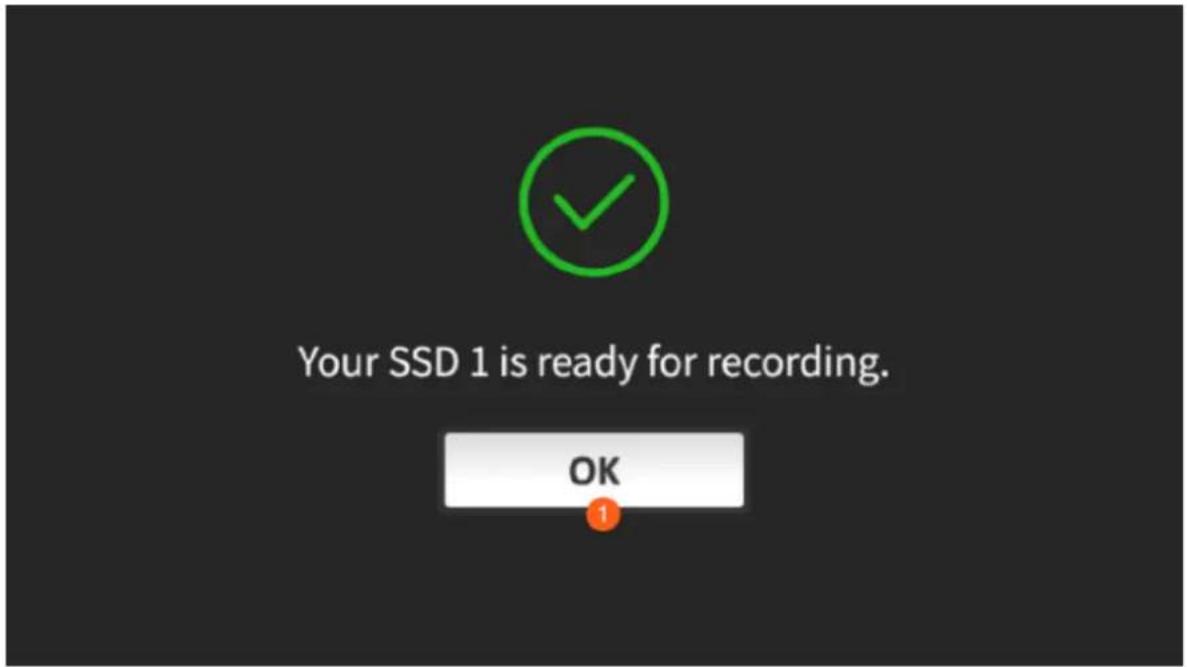
If the disk format fails, you will also be prompted. Tap "OK" to re-run the process.
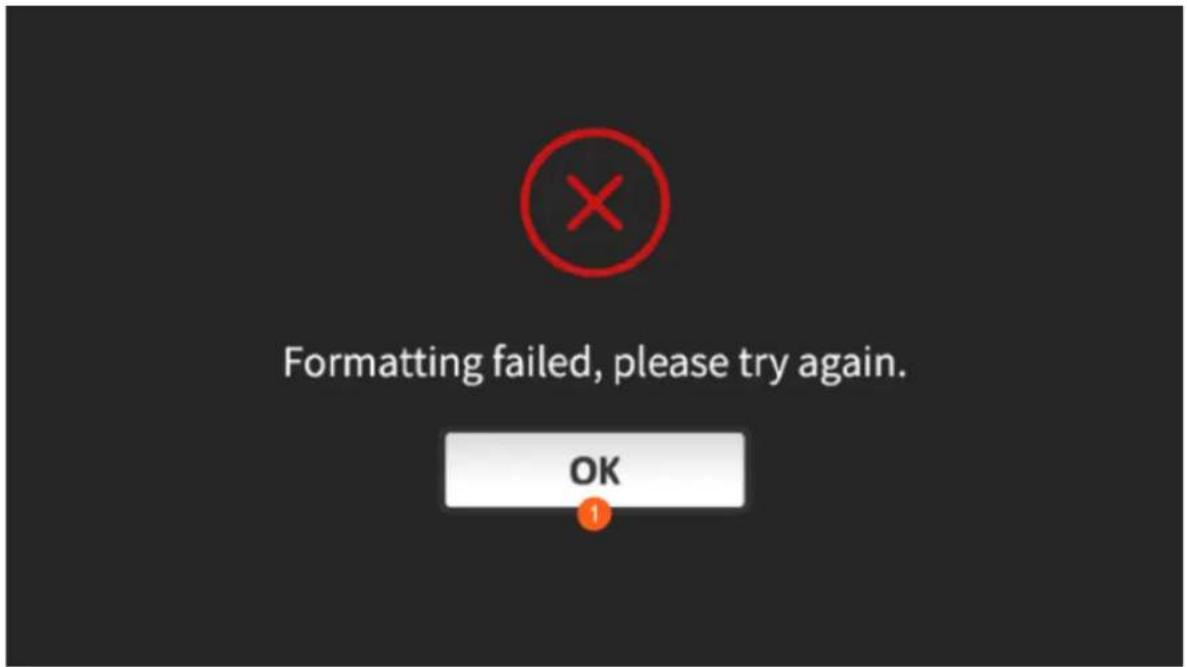
XLR Setup
The XLR Setup page allows you to select the audio format and set the audio level for XLR input/output.
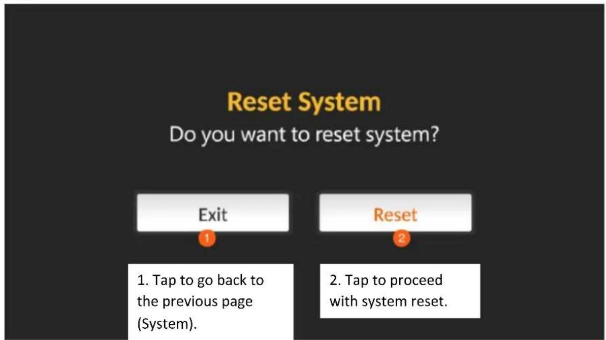
Reset
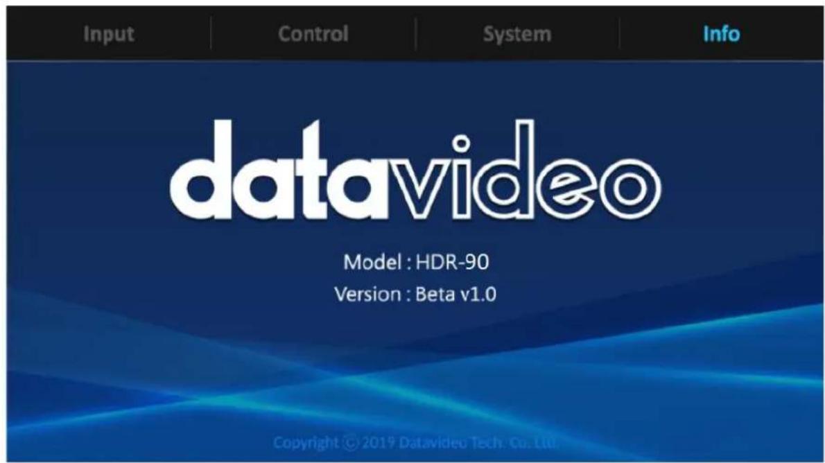
4.3.4 Info
5. Firmware Update
Datavideo usually releases new firmware containing new features or reported bug fixes from time to time. Customers can either download the firmware as they wish or contact their local dealer or reseller for assistance.
This section outlines the firmware upgrade process which should take approximately few minutes to complete.
The existing settings should persist through the firmware upgrade process, which should not be interrupted once started as this could result in a non-responsive unit.
Firmware Upgrade Requirements
- SSD
- Latest firmware files
Upgrade Procedure
- Save the latest firmware files on the SSD.
- Install the SSD in a removable disk enclosure.
- Insert the drive enclosure into the recorder and move the locking latch from right to left side to secure the drive enclosure in place.
- After turning on the HDR-90's power, the firmware will be automatically updated.
- You should be able to see a progress bar displayed on the screen. Do not shut down the recorder or remove the drive enclosure during the update process.
- You will be prompted to reboot the HDR-90 once the update is complete.
Note: If you are prompted that the firmware update fails, please reboot the HDR-90 to restart the firmware update process.
6. Frequently Asked Questions
This section describes problems that you may encounter while using HDR-90. If you have any questions, please refer to related sections and follow all suggested solutions. If problem still exists, please contact your distributor or the service center.
| No. | Problems | Solutions |
| 1. | The connected monitor cannot display 4K HDMI video sent from the HDR. | Check if your 4K monitor supports 4:2:2 because this is the only format that the HDR unit supports. Please change a monitor if the connected monitor supports 4:2:0 or lower or connect the monitor to HDMI OUT 2 or 3. |
| 2. | The HDR unit cannot detect 4K HDMI video. | Please reboot your HDR unit or unplug the HDMI cable then plug back in. If the problem still exists, check whether your video source format is 4:2:0 or DVI/HDCP, because they are not supported by the HDR. |
| 3. | Can I record the video to two SSDs at the same time? | No, the HDR unit does not allow the user to access the two disks at the same time. The dual disk design is to allow the HDR to switch to SSD2 to continue recording when the SSD1 is full. While recording, the system will display an insufficient capacity error message when the storage space runs out. |
| 4. | The HDR unit fails to receive the 12G SDI video over the 100 meter cable. | First check whether the cable is 12G SDI compliant.For example, if you are using an 100m Canare SDI cable, you will then need to make sure the cable is 5.5C UDH or above. If you are using a 3G SDI cable, the maximum allowable distance is approximately 70 meters.Low grade cables have a transmission distance of less than 1 meter so if you need to send 4K SDI video over a long distance, please first make sure your cable is 12G SDI compliant. |
| 5. | Can I send video to and from the HDR unit over long HDMI cables? | Yes, you may send video to and from the HDR unit over long HDMI cables but HDMI Licensing Administrator, Inc. does not specify the maximum transmissible HDMI cable length which is entirely dependent on the device capability and the cable grade. For long distance transmission, we recommend using cables approved by HDMI Licensing Administrator, Inc. to ensure quality of transmission. |
| 6. | The monitor displays a grey screen and the recorder's functions and buttons are inactive. The HDR-90 must be rebooted to restore its functionalities. | The boot failure issue could be due to improper device shutdown. The system requires some time to shut down the device, particularly if it is performed right after the file save. It could take longer for the system to complete the file save process, as a result, we recommend long pushing the switch button for at least 6 seconds. |
| 7. | The built-in LCD touch screen shows a black screen or displays incorrectly. | Make sure that input channel 1 has been connected of a video source. If input channel 1 is left unconnected, you might experience a black screen or incorrect display on the built-in LCD touch screen. |
7. Dimensions
HDR-90

natural_image
Front panel of a network equipment rack with multiple ports and indicator lights (no visible text or labels)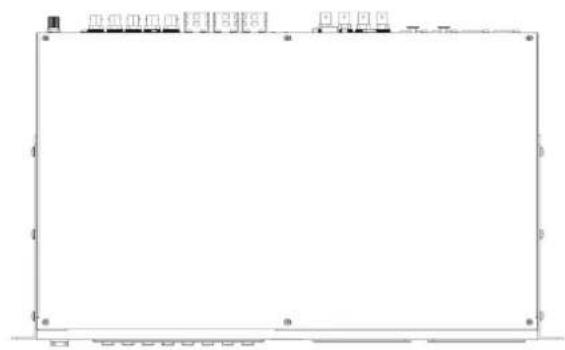
natural_image
Empty rectangular frame with grid layout and small icons at top (no text or symbols)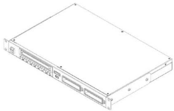
natural_image
Line drawing of a rectangular electronic device with ports and mounting brackets (no text or symbols)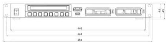
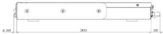
All measurements in millimeters (mm)
- Product Specifications
| Video Input | Specifications | |
| SDI | 1 x 12G/3G-SDI3 x 3G/HD-SDI | SMPTE 2082SMPTE 425M Level A & B SMPTE 292M, SMPTE 296M |
| HDMI | 1 x HDMI 2.01 x HDMI 1.4 | |
| Video Output (Play/Loop Out) | Specifications | |
| SDI | 1 x 12G/3G-SDI | |
| HDMI | 1 x HDMI 2.03 x HDMI 1.4 | |
| Audio Input | Specifications | |
| Balanced Audio | 2 x XLR (Balanced Audio) | 1 KHz Level: 4dBu±0.5dBFrequency Response (20 Hz ~ 20 KHz): 4dBu±0.5dB S/N ≥ 80dBDistortion ≤ 0.01%Crosstalk ≥ 80dB ±12dB Adjustable |
| SDI Embedded | 8 Channel | 48 KHz, 24 bit |
| HDMI Embedded | 8 Channel | 48 KHz, 24 bit |
| Audio Output | Specifications | |
| Balanced Audio | 2 x XLR (Balanced Audio) | 1 KHz Level: 4dBu±0.5dBFrequency Response (20 Hz ~ 20 KHz): 4dBu±0.5dB S/N ≥ 80dBDistortion ≤ 0.01%Crosstalk ≥ 80dB ±12dB Adjustable |
| SDI Embedded | 8 Channel | 48 KHz,24 bit |
| HDMI Embedded | 8 Channel | 48 KHz, 24 bit |
| Audio Monitor / Alarm | Speaker Earphone | Speaker: 4Ω3.5mm Stereo EarphoneJack Volume Adjustment |
| Supported Formats (Record & Playback) | Specifications | |
| UHD | 2160p23.982160p 242160p 252160p 29.972160p 302160p 502160p 59.942160p 60 | 10 bit 4:2:2Note: 4:2:0 Chromasubsampling is not supported. |
| 3G, HD | 1080p23.981080p241080p251080p29.971080p501080p59.951080p601080i501080i59.941080i60720p50720p59.94720p60 | 10 bit 4:2:2Note: 4:2:0 Chromasubsampling is not supported. |
| Supported CODEC | Specifications | |
| ProRes | ProRes HQ 4:2:2ProRes Standard 4:2:2ProRes LT 4:2:2ProRes Proxy 4:2:2 | 1 Channel: UHD, HD (3G/1.5G)4 Channels: HD (3G/1.5G)for Record Mode Only |
| Audio Recording Format | Uncompressed PCMSampling rate 48 KHz 24 bit | |
| Recording Media | Specifications | |
| Drive Slots | 2 x SATA | SATA-3 (6G) Samsung 860Pro SSD and 870 EVO SSD onlyHot Plug (cannot remove drive during recording) |
| Media Type | SATA-III SSD (Solid State Disc) | |
| File System | exFAT | |
| Recorded File Format | QuickTime .MOV | |
| Time Code | Specifications | |
| LTC Input | 1 x BNC | SMPTE 291M |
| LTC Out/Loop | 1 x BNC | SMPTE 291M |
| ATC_LTC / ATC_VITC | SDI | RP-188, SMPTE 12M-2 |
| D-VITC | SDI | SMPTE 266 |
| Gen-Lock (Play Out) | Specifications | |
| Reference IN | 1 x BNC | Black BurstTri-Level Cross Reference |
| Reference Loop OUT | 1 x BNC | |
| Closed Caption | Specifications | |
| Input / Output | SDI Embedded QuickTime | CEA-608CEA-708 RP-2007-2007SMPTE 2052 |
| Touchscreen Display | Specifications | |
| Size | 5" | Video: MIPI 4 Lane |
| Resolution | 1280 x 720 | Capacitive Touch: I^2C Interface |
| Aspect | 16:9 Native | |
| Video Input | Specifications | |
| Button | 8 x Buttons | Rubber Key |
| Backlight LED | White LED | |
| Function LED | Color LED | |
| Monitor Tools | Specifications | |
| Analysis | Focus Assist Zebra | TBD |
| Overlay | Waveform Histogram Vector Scope | TBD |
| Remote Control | Specifications | |
| SDI/HDMI | Time Code Trigger | |
| Ethernet | 1 x RJ-45 | DVIP Protocol |
| RS-232/422 | 1 x DSub-9 | RS-232/422 Selectable Sony 9pin Remote Protocol |
| GPI Trigger | 1 x 3.5mm Stereo Phone Jack | Trigger Input: Edge or Level Trigger Selectable Tally Output: 3.3V@10mA |
| USB | 1 x USB Type A | USB HID Device USB is non-functional in recorder mode. |
| General | Specifications | |
| Operating Temperature | 0°C to 40°C (32°F to 104°F) | |
| Storage Temperature | -20°C to 60°C (-4°F to 140°F) | |
| Humidity | 10% - 80% (non-condensing) | |
| Dimensions (mm) | 313.5 x 220.0 x 97.0 | |
| Weight | 2.8 Kg | |
Notes
Service & Support
It is our goal to make owning and using Datavideo products a satisfying experience. Our support staff is available to assist you to set up and operate your system. Contact your local office for specific support requests. Plus, please visit www.datavideo.com to access our FAQ section.
Please visit our website for latest manual update.
www.datavideo.com/product/HDR-90
datavideo
www.datavideo.com

@DatavideoUSA @DatavideoIndia2016
@DatavideoEMEA @Datavideojapan
@DatavideoTaiwan @DatavideoLatam
@DatavideoAsia @DatavideoBrasil

@DatavideoUSA
@DVTWDVCN

@Datavideo
@Datavideo EMEA
@Datavideo_Taiwan

@DatavideoUSA
@DatavideoEurope
- Table of Contents
- FCC COMPLIANCE STATEMENT....4
- WARNINGS AND PRECAUTIONS......4
- WARRANTY 5
- DISPOSAL 6
- PRODUCT OVERVIEW 7
- CONNECTIONS AND CONTROLS....9
- SSD SLOTS....20
- HUMAN MACHINE INTERFACE....23
- Disclaimer of Product & Services
- FCC Compliance Statement
- Warnings and Precautions
- Warranty
- Standard Warranty
- Three Year Warranty
- Disposal
- For EU Customers only - WEEE Marking
- Product Overview
- Features
- System Diagram
- Connections and Controls
- With Headphone Monitoring
- Power On / Off Button
- Headphone Audio Monitoring
- Menu Button
- CLIP Button
- SEL DRIVE
- Stop Button
- Play / Pause Button
- Record Button
- Rew Button
- Fwd Button
- USB Port
- SD Card Slot
- Rear Panel
- DC IN Socket
- Grounding Terminal
- 3G\*/12G\*\*-SDI Input and Output
- 3G\*-SDI Inputs
- HD/4K-HDIM Input and Output
- HD-HDMI Outputs
- Genlock IN / OUT
- Time Code Signal IN /OUT
- XLR Analog Audio IN
- XLR Analog Audio OUT
- Ethernet Port
- GPI Control
- RS-232/422 Remote Control
- Without Headphone Monitoring
- SSD Slots
- Install an SSD in a Removable Disk Enclosure
- Notes:
- Human Machine Interface
- Dashboard
- Record State
- Audio Indicator
- Disk Information
- Sub-Menu
- Focus Assist
- Zebra
- Waveform
- Histogram
- Vectorscope
- Loop Play
- Multiview
- LCD Display
- CLIP
- Bin with Multiple Clips
- Single Clip Deletion
- Multiple Clip Deletion
- MENU
- Input
- ProRes Quality
- HQ 4:2:2
- Standard 4:2:2
- LT 4:2:2
- Proxy 4:2:2
- Input Channel Setup
- PsF Setup
- XLR Setup
- Time Code
- Control
- System
- Format SSD
- Format SSD 1
- Format SSD1
- Info
- Firmware Update
- Firmware Upgrade Requirements
- Upgrade Procedure
- Frequently Asked Questions
- Dimensions
- Notes
- Service & Support
Brand : DataVideo
Model : HDR-90
Category : Video recorder