
UHT800 - Microphone Bogen - Free user manual and instructions
Find the device manual for free UHT800 Bogen in PDF.


| Product Type | Wireless Handheld Microphone Transmitter |
| Frequency Range | 470 MHz - 490 MHz (U.S.) |
| Number of Channels | 800 user-selectable (25 kHz steps) |
| RF Output Power | +17 dBm max, +14 dBm typical (25 mW) |
| Modulation | FM (F3E), +/-25 kHz normal, +/-75 kHz max |
| Battery Type | 2 x AA alkaline or NiMH |
| Battery Life | 8-10 hours typical (alkaline) |
| Dimensions | 9.125 in x 2 in diameter (23.1 cm x 5.1 cm) |
| Weight (without batteries) | 10 oz (283 g) |
| Housing Material | Metal |
| Antenna Type | Integral (windscreen acts as antenna) |
| Frequency Stability | <0.005% (PLL synthesized) |
| Audio Controls | Power On/Off, Audio Mute, Input Level adjustment |
| LED Indicators | Power On (green), Low Battery (red) |
| IR Programming | IR sync with UDR800 receiver for frequency matching |
| Operating Range | Up to 500 ft line-of-sight (with receiver) |
| Warranty | 1 year limited (from date of purchase) |
| Maintenance | Clean with dry soft cloth; avoid moisture and extreme temperatures |
| Safety | FCC compliant: low power, no license required for typical use |
| Spare Parts | AA batteries, windscreen (integral antenna) |
Frequently Asked Questions - UHT800 Bogen
User questions about UHT800 Bogen
0 question about this device. Answer the ones you know or ask your own.
Ask a new question about this device
Download the instructions for your Microphone in PDF format for free! Find your manual UHT800 - Bogen and take your electronic device back in hand. On this page are published all the documents necessary for the use of your device. UHT800 by Bogen.
USER MANUAL UHT800 Bogen
UDMS800HH
Handheld Uni-directional Microphone w/ UHF Receiver
UDMS800BP
Body-Pack & Lavaliere Microphone w/ UHF Receiver
INSTRUCTION MANUAL
CONTENTS
INTRODUCTION ....1
USING THIS MANUAL....1
SYSTEM FEATURES ...... 2
UDR800 RECEIVER 3-5
UHT800 HANDHELD MICROPHONE TRANSMITTER....6-7
UBP800 BODY-PACK MICROPHONE TRANSMITTER....8-9
SELECTING GROUP/CHANNEL, IR PROGRAMMING, MULTICHANNEL ....10-12
FRONT PANEL LOCK-OUT 12
RF INTERFERENCE & FINDING OPEN CHANNELS 12
FREQUENCY PLAN 13
FREQUENCY LISTINGS ....13
SPECIFICATIONS....14
LIMITED WARRANTY 15
INTRODUCTION
Thank you for purchasing a Bogen UHF PLL Synthesized Microphone System. This system includes high quality professional operating features and is the best performance and price value available in UHF PLL Synthesized wireless systems.
USING THIS MANUAL
This manual lists the features of the UDM800BP/HH Wireless System and takes you step-by-step through operation of the system. After reading the receiver instructions, turn to the section of the booklet that covers the type of transmitter used with your new system. Each section will give you detailed operating instructions. Also included in this manual are system specifications and servicing information.
SYSTEM FEATURES
UDR800 RECEIVER
- Unsurpassed state-of-the-art PLL UHF performance with 120 dB dynamic range and operation, up to 500 ft. (line-of-sight)
- 800 user-selectable UHF frequencies, one touch Auto-Scan/Sync open channel automatic selection and sync
- ASC™ (Auto-Sync Channels) download feature sends selected Channel information to transmitter via IR sender for easy frequency synchronization
- Sophisticated IF filtering for optimal simultaneous operation of multiple systems in same location
- DigiTRU Diversity™ for maximum range and dropout protection
- 120dB Dynamic Range — the quietest and best sounding UHF wireless available at any price
- Tone Squelch™ for locking out potential interference, and special circuitry for noiseless transmitter ON/OFF switching
- Dual front panel permanently attached swivel antennas
- Front panel with LCD displays A/B diversity, Group/Channel with frequency, ASC™ transfer status, RF/AF level, Mute (squelch) level, and push On/Off power switch
- Back panel with fixed Balanced XLR, MIC Level and adjustable unbalanced 14 jacks, audio Line outputs and DC input jack
• Half-rack receiver design with top folding dual antennas - Unique snap-out side panel locking tabs for single receiver or dual receivers (side-by-side) optional rack mounting (mounting kits sold separately)
- Externally powered with included DC adapter (22V DC 400 mA)
- Choice of transmitters: UHT800 Handheld MIC or UBP800 Body-Pack
UHT800 HANDHELD MIC TRANSMITTER
- Sleek metal housing with internal antenna for optimum aesthetics and durable long life
- Unidirectional neodymium dynamic cartridge for optimum true sound, maximum feedback rejection and minimal handling noise
- 800 easily selectable channels via IR Sync for easy synchronization with receiver selected channel
- Easy accessible audio level adjustment for optimum sound
- Power On/Off and Audio mute switch allows convenient audio muting with the transmitter "ON"
- Status LED indicators for unit "ON" (Green) and for low battery alert "ON" (Red)
- Convenient, economical operation with two AA alkaline or NiMH batteries
UBP800 BODY-PACK TRANSMITTER
- 800 easily selectable channels via IR Sync for easy synchronization with receiver selected channel
- Easy accessible input level adjustment for optimum sound
- Power On/Off and Audio mute switch allows convenient audio muting with the transmitter "ON"
- Bi-color LED status indicator for unit "ON" (Green) and for low battery alert "ON" (Red)
- Convenient, economical operation with two AAA Alkaline or NiMH batteries
- Ultra compact housing, removable antenna and unique locking 3.5mm mini plug connector for the microphone cable
1. Rack Mounting the Receiver
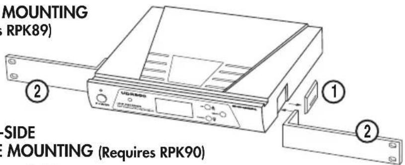
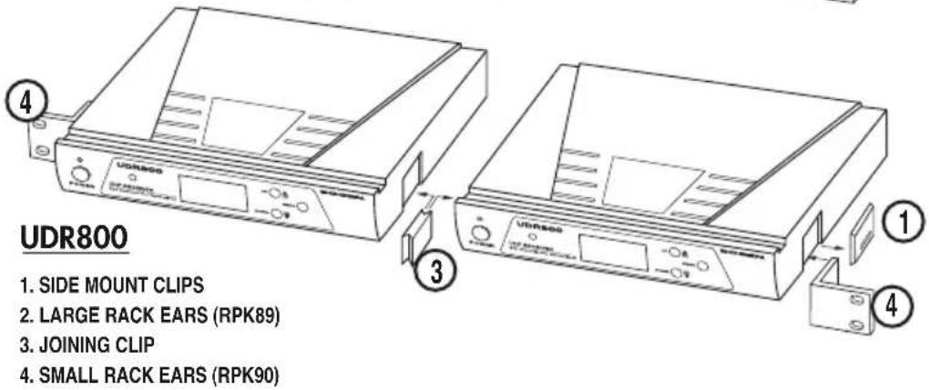
There are 2 options available (as accessories) for rack mounting the UDR800 receiver: single or side-by-side with another UDR800 receiver.
A. Single Mounting (RPK89): Remove the receiver SIDE MOUNT CLIPS (1) from each side of the receiver (as shown) and slide in the optional wider RACK EARS (2). (see page 4)
B. Side-by-Side Double Mounting (RPK90): After removing the SIDE MOUNT CLIPS (1) from both UDR800 receivers, join the two receivers with the JOINING CLIP (3) and attach the narrow RACK EARS (4) as shown. (see page 4)
(Note: Do not mount the receiver in a rack directly above an amplifier or other source of high heat — this could degrade the performance of the UDR800. Always ensure adequate airflow and heat dissipation in any rack configuration.)
2. Powering the Receiver
Plug the 22V DC ADAPTER (28) provided into the DC INPUT JACK (6) on the back of the receiver. Then plug the power supply into an AC outlet. Press the POWER SWITCH (9) once to turn on the receiver. The POWER "ON" LED (10) will now light and the receiver is operational.
3. Antennas
The UDR800 receiver is equipped with attached dual FOLDING ANTENNAS (11). Optimal positions of the antennas are 45^ from the receiver (or 90^ from each other). For maximum range, it is always best to maintain a line-of-sight (no obstructions) between the receiver antennas and the transmitter at all times whenever possible.
4. Adjusting the Mute Level/RF Squelch
The MUTE LEVEL/RF SQUELCH (24) can be changed anytime during the main screen display to quiet the receiver in high noise environment conditions. The control ranges are from level 0 to level 5. The level should be adjusted to a lower number to the minimum RF squelch setting at which the RF INDICATOR (19) will remain on while your transmitter is in normal use, up to the maximum operating range anticipated in use for your application. However, in areas of high RF activity, the squelch control may need to be adjusted to a higher number. If the transmitter is off and the receiver signal RF INDICATOR (19) or the diversity A or B INDICATOR (20) flickers or stays on continuously, the squelch should be adjusted to a higher number to stop the flickering. Be careful not to select too high a number setting as this may reduce the operating range to below what is needed. A range walk test will help in selecting the proper level. If the range is not critical, note that a higher level (maximum squelch) setting will also yield a quieter mute function, which might be desired in certain applications. The squelch level is factory preset at maximum sensitivity and operating range (i.e. level 0 for minimum squelch level — maximum usable range).
(Note: For easier intuitive operation, the MIN and MAX indicators for this control refer to the minimum and maximum operating range settings, not to the actual mute levels selected, which are the opposite as per above.)
UDR800 RECEIVER
5. Audio Level and Peak LED Indicator
The UDR800 receiver has a 5-bar AF LCD (18) display that indicates normal level audio signal from the transmitter. Occasional flickering of the fifth AF LCD (peak level) on loud inputs to the transmitter is normal. If the AF LCD (18) lights up full bars continuously, decrease the input audio level to the transmitter or overload distortion may result.
6. Connecting the Audio Output
The UDR800 receiver provides both a fixed MIC level BALANCED MIC OUTPUT XLR (8) and an adjustable unbalanced line level AUDIO OUTPUT 1/4"Jack (5).

Output 1/4" Jack

(Note: As when making any connection, make sure the amplifier or mixing board volume is at the minimum level before plugging in the receiver to avoid possible sound system damage.)
A. SINGLE MOUNTING (Requires RPK89)
B. SIDE-BY-SIDE DOUBLE MOUNTING (Requires RPK90)
REAR VIEW
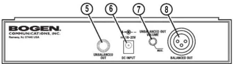
- UNBALANCED LINE OUT 1/4" JACK
- DC INPUT JACK
- UNBALANCED OUT VOLUME CONTROL
- BALANCED MIC OUT XLR JACK
-
POWER BUTTON
-
POWER LED INDICATOR
- FOLDING ANTENNAS
- ASC/IR LED INDICATOR
- UP BUTTON
- MENU BUTTON
- DOWN BUTTON
- LCD DISPLAY

- MUTE ICON
- AF INDICATOR
- RF INDICATOR
- A & B INDICATORS
- GROUP NUMBER
- IR INDICATOR
- CHANNEL NUMBER
- MUTE LEVEL
- SCAN ICON
- FREQUENCY
- LOCK OUT ICON
- DC POWER SUPPLY ADAPTER


natural_image
Simple line drawing of a mechanical component with a numbered label (28) and no readable text or symbols.UHT800 HANDHELD MIC TRANSMITTER
1. Microphone Battery Installation
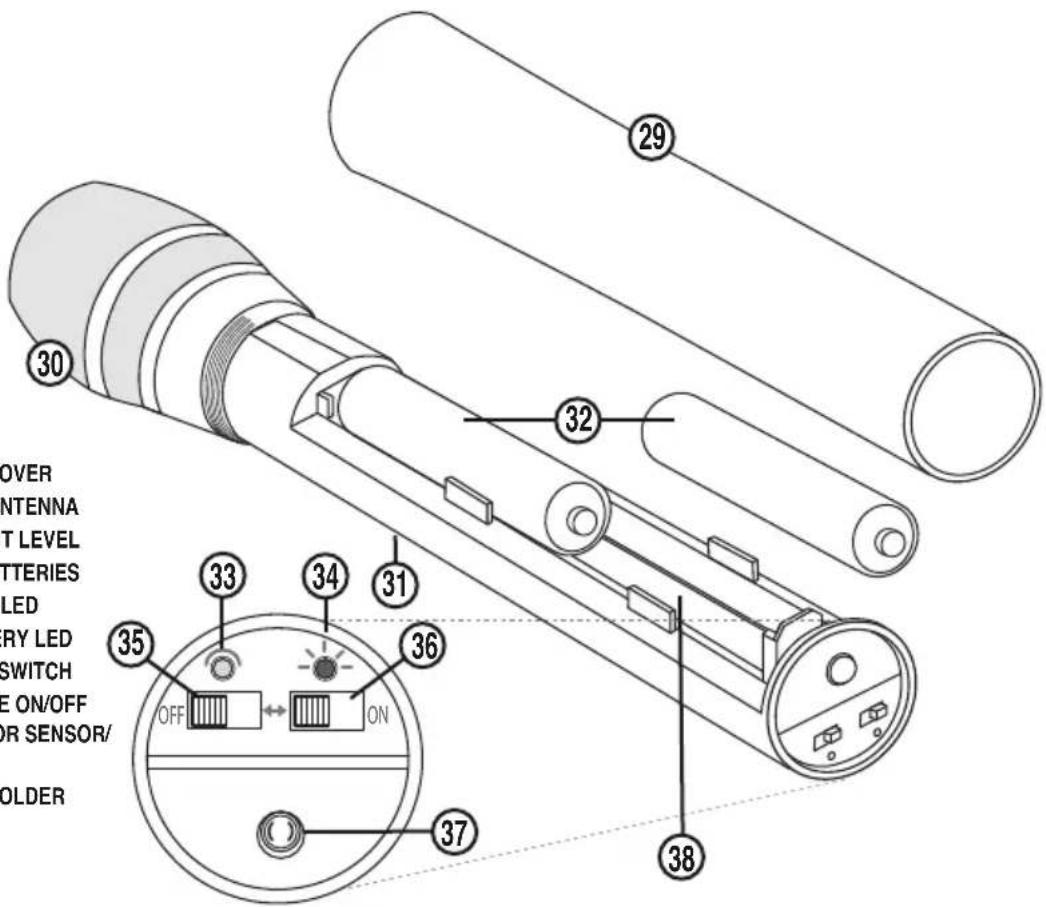
Install batteries by unscrewing the BATTERY COMPARTMENT COVER (29) counterclockwise and remove, exposing the BATTERY HOLDER (38). Insert two fresh AA ALKALINE BATTERIES (32), observing the correct polarity, and screw the cover back on to the microphone. Make sure the cover is screwed clockwise completely. Fresh alkaline batteries can last up to 10 hours in use, but in order to ensure optimum performance, it is recommended that you replace the batteries after every 7-8 hours of use.
2. Programming UHT800 to Selected Group/Channel (Frequency)
The transmitter must be programmed to the same frequency as selected for the receiver via automatic synchronization using the IR ASC™ Sync function. It can not be programmed on the transmitter itself. See "Selecting the Receiver Group/Channel and Programming" in next section. To manually IR program the receiver preselected frequency into the transmitter, place the transmitter's IR RECEPTOR SENSOR WINDOW (37) 6-12" away from the receiver's IR WINDOW (12). Press the MENU BUTTON (14) four times to the IR Screen then press the UP BUTTON (13) to start IR programming. This flashing IR INDICATOR (22) icon indicates IR transmission is in progress. When the synchronization is completed successfully, the RF INDICATOR (19) and the diversity A or B INDICATOR (20) on the receiver will show up. (See section on Selecting the Group/Channel (Frequency) and IR Programming for transmitters.)
(Note: If no button is pressed for a five second period during a selection, the program is terminated and the process needs to be repeated.)
3. Operating the UHT800 Handheld MIC Transmitter
Turn on the UHT800 by sliding the AUDIO MUTE (36) to the OFF position first. Then slide the POWER SWITCH (35) to the ON position. The TX LED INDICATOR (green) (33) will stay on to indicate that the transmitter is on. The LOW BATTERY INDICATOR LED (red) (34) will stay OFF, indicating usable-battery strength. In the case of a dead battery, the BATTERY INDICATOR LED (34) will stay on continuously, indicating that the batteries should be replaced. To preserve battery life, turn the transmitter off when not in use.
The microphone is now ready to use. The A or B DIVERSITY LED INDICATOR (20) on the UDR800 receiver should now be lit, indicating a received signal from the transmitter. When ready to speak, slide the AUDIO MUTE (36) to the ON position.
(Note: Observe care in selecting P.A. volume, transmitter location and speaker placement so that acoustic feedback (howling or screeching) will be avoided.)
(Note: The windscreen of the UHT800 functions as a built-in antenna. For proper operation, never remove the windscreen during use, or exchange with another type. For optimum range, maintain line-of-sight between the transmitter and the receiver whenever possible. Holding the microphone tightly, bridging across the windscreen and mic tube, will also lessen range. Hold MIC by the MIC tube housing only for optimum operation.)
For optimum performance, an AUDIO INPUT LEVEL (31) is provided. Adjust the gain by turning the control with a small screwdriver. It is recommended that the level be set at about 1/2 maximum. Experiment and set for maximum possible gain without audible distortion on the high level peaks.
(Note: Turning down the gain too much can compromise the signal-to-noise ratio, and is not recommended.)
UHT800 HANDHELD MIC TRANSMITTER
UHT800
- BATTERY COVER
- MIC BALL/ANTENNA
- AUDIO INPUT LEVEL
- TWO AA BATTERIES
- POWER ON LED
- LOW BATTERY LED
- RF POWER SWITCH
- AUDIO MUTE ON/OFF
- IR RECEPTOR SENSOR/WINDOW
- BATTERY HOLDER
1. UBP800 Body-Pack Battery Installation
Open the BATTERY DOOR (47) by pulling on side tabs and swinging the lid open. Insert two fresh AAA Alkaline Batteries into the BATTERY COMPARTMENT (46), observing the correct polarity. Fresh alkaline batteries can last up to 8 hours in use, but in order to ensure optimum performance, it is recommended that the batteries be replaced after 5-6 hours of use.
2. Lavaliere MIC Connection/Operation
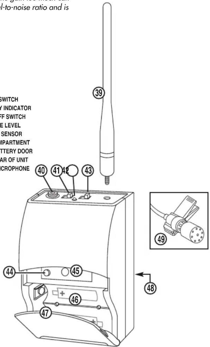
The UBP800 is provided with a 3.5 mm INPUT JACK (40) for connecting the audio input. Connect the LAVALIERE MIC CORD (49) here. To secure the connection, turn the slip ring on the plug clockwise to thread it on the jack. To unplug, reverse the process. To use the Lavaliere MIC, attach it at chest level. Do not place it too close to the mouth. A distance of about six inches usually works best. When ready to speak, slide the AUDIO MUTE SWITCH (41) to the ON position.Slip the transmitter into a pocket or use the CLIP (48) on the rear of the unit to attach to your clothes
3. Programming UBP800 to Selected Group/Channel (Frequency)
The transmitter must be programmed to the same frequency as selected for the receiver via automatic synchronization using the IR ASC™ Sync function. It can not be programmed on the transmitter itself. See "Selecting the Receiver Group/Channel and Programming" in next section.
To manually IR program the receiver preselected frequency into the transmitter, place the transmitter's IR RECEPTOR SENSOR WINDOW (45) 6-12" away from the receiver's IR WINDOW (12). Press the MENU BUTTON (14) four times to the IR Screen then press the UP BUTTON (13) to start IR programming. This flashing IR INDICATOR (22) icon indicates IR transmission is in progress. When the synchronization is completed successfully, the RF INDICATOR (19) and the diversity A or B INDICATOR (20) on the receiver will show up. (See section on Selecting the Group/Channel (Frequency) and IR Programming for transmitters)
(Note: If no button is pressed for a five second period during a selection, the program is terminated and the process needs to be repeated.)
4. Operating the UBP800 Body-Pack MIC Transmitter
Turn on the UBP800 by sliding the AUDIO MUTE SWITCH (41) to the OFF position first, then slide the POWER SWITCH (43) to the ON position. The bi-color LOW BATTERY INDICATOR (42) will stay ON (green) indicating usable battery strength and that the transmitter is ON. In the case of dead or low batteries, the LED will either not go on at all or will stay ON (red) continuously, indicating that the batteries should be replaced with fresh ones. To preserve battery life, turn the transmitter OFF when not in use. The A or B DIVERSITY LED INDICATORS (20) on the UDR800 receiver should now be lit, indicating that signal is being received from the transmitter.
(Note: The UBP800 is supplied with a removable ANTENNA (39). It should always be operated with the supplied antenna. For optimum operating range, always maintain line-of-sight between the transmitter and the receiver whenever possible.)
5. Microphone Use
Secure the connection from the LAVALIERE MIC (49) to the INPUT JACK (40) on the Body-Pack. To use the LAVALIERE MIC (49), attach it to the body at chest level. Do not place the MIC too close to the mouth. A distance of about six inches usually works best. When ready to speak, slide the AUDIO MUTE SWITCH (41) to the ON position.
UBP800 BODY-PACK MIC TRANSMITTER
(Note: Observe care in selecting P.A. volume, transmitter location, and speaker placement so that acoustic feedback (howling and screeching) will be avoided. Please also note the pickup pattern characteristics of the microphone selected. Omni-directional mics pickup sound equally from all directions, and are prone to feedback if not used carefully. Uni-directional mics are more resistant to feedback, but best pick up sound sources that are directly in front of the mic. Also, mics that are farther from the sound source, such as lavalieres, require more acoustic gain and thus are more prone to feedback than close-source mics such as handheld models that are used close to the mouth.)
For optimum performance, an INPUT VOLUME LEVEL (44) is provided. Adjust the gain by turning the control with a small screwdriver. For lavaliere mic use, it is recommended that the level be set at about 2/3 maximum. Experiment and set for maximum possible gain without audible distortion on the high level peaks.
(Note: Turning down the gain too much can compromise the signal-to-noise ratio and is not recommended.)
UBP800
- ANTENNA
- INPUT JACK
- AUDIO MUTE SWITCH
- LOW BATTERY INDICATOR
- POWER ON/OFF SWITCH
- INPUT VOLUME LEVEL
- IR RECEPTOR SENSOR
- BATTERY COMPARTMENT
- LATCHING BATTERY DOOR
- BELT CLIP/REAR OF UNIT
- LAVALIERE MICROPHONE
SELECTING THE GROUP/CHANNEL, IR PROGRAMMING, AND SIMULTANEOUS MULTICHANNEL OPERATION
(Note: The transmitter should be turned ON and ready for the IR communications with the receiver IR receptor for the following process.)
(Note: If no button is pressed for a five second period during a selection, the program is terminated and the process needs to be repeated.)
(Note: For normal operation, the transmitter should have the same channel as displayed on the receiver.)
Choosing Group/Channel for the System
The receiver offers a choice of 15 groups: 10 that are Factory PRESET (Group 11 to 1A) and 5 that are User SELECTABLE (Group 1B to 1F). If the Factory PRESET Group mode is chosen, only a limited numbers of channels are available in these groups. For most convenient setup, each of these groups offers from 3 to 14 channels (depending on group selected) to choose from that are factory preset for simultaneous multichannel operation compatibility and are retained in memory after the receiver is powered off. For the User SELECTABLE Group 1B-1F mode, a letter "U" will light up on the LCD DISPLAY (16) instead of the CHANNEL (23) number as in the Factory PRESET Groups. Each User SELECTABLE Group has 800 channels to choose from either by manually selecting a channel or using the Auto-Scan in 1MHz segment increments at a time within the frequency band and they are retained in memory after the receiver is powered off. This facilitates easy setup by enabling quick selection of stored channels for any group, i.e., selecting any group will automatically display the last channel selected for that group. See Frequency Listings section for available channels in each group. The previous group and channel used is stored in memory automatically when receiver and transmitter are turned off after operation. Selecting a different group on the receiver in subsequent use will display a different channel as previously selected for that group, however, the transmitter will need again to be sync'ed to that new frequency to complete the system setup for operation.
Receiver ASC™/IR Sync GR/CH (Frequency)
If different frequencies than previously stored in both the receiver and transmitter memories are needed, there are three ways to program the receiver and then sync the selected Group/Channel to the transmitter: One-Touch Automatic ASC™/Auto Sync receiver to transmitter, manual SCAN for Group/Channel, or manual select Group/Channel from the Factory preset or User Selectable channel. Place the transmitter's IR RECEPTOR SENSOR WINDOW (37) 6-12" away from the receiver's IR WINDOW (12) before starting the following steps.
- For One-Touch channel Autoscan and Automatic ASC™/Auto Sync from the receiver to the transmitter, press the MENU BUTTON (14) once, wait for about 5 seconds, the receiver will start the process automatically with no further user action required. A running bar in a clockwise direction on the LCD DISPLAY (16) shows the scanning process which normally takes about two seconds. When it finds an interference-free channel, the receiver stores the channel for use, and it will begin ASC™ sync IR download of the selected channel to the transmitter automatically.
- To manually scan the selected Group/Channel, press the MENU BUTTON (14) twice for the AUTOSCAN menu, press the UP BUTTON (13) once and it will start scanning. A running bar in a clockwise direction shows the scanning process, which normally takes about 2 seconds. When it finds an interference-free channel, it will display and store the frequency/channel for use. It can be rescanned again for a new frequency by press-
SELECTING THE GROUP/CHANNEL, IR PROGRAMMING, AND SIMULTANEOUS MULTICHANNEL OPERATION
ing the UP BUTTON (13) or by pressing the MENU BUTTON (14) twice to IR MENU (IR icon will light up for IR function), then press the UP BUTTON (13) to start IR programming.
- To manually select Group/Channel, press the MENU BUTTON (14) once for GROUP (21) selection for Factory PRESET Group 11 to 1A mode or User SELECTABLE Group 1B to 1F mode. Use the UP/DOWN buttons to change the group. After selecting a group, press the MENU BUTTON (14) twice for channel selection menu. Use the UP/DOWN buttons to change the channels (frequencies) that are available in each group.
(Note: for Group11 to 1A, the CH (23) display will indicate the channel number chosen, and for Group 1B to 1F only the letter "U" and the frequency chosen will be displayed. See Frequency Listings section for available channels in each group.)
After finishing channel selection, press the MENU BUTTON (14) once or wait a few seconds for IR MENU, and then press the UP BUTTON (13) to start IR programming.
This completes the GP/CH (frequency) programming. The next section outlines the procedure for sync'ing the receiver's programmed channel to the transmitter.
Receiver ASC™/IR Sync Manual Programming
To manually program the pre-selected Group/Channel (frequency) from the receiver to the transmitter, place the transmitter's IR RECEPTOR SENSOR WINDOW (37) 6-12" away from the receiver's IR WINDOW (12). Press the MENU BUTTON (14) four times to the IR Screen Display and then press the UP BUTTON (13) to start IR programming. The flashing IR INDICATOR (22) icon indicates IR transmission is in progress. When the synchronization is completed successfully (usually in less than 2 seconds), the RF INDICATOR (19) and the diversity A or B INDICATOR (20) on the receiver will display, indicating that the IR linking is completed. The LCD DISPLAY SCREEN (16) will show the selected channel. If the UP Button is not pressed during the two seconds of active data transfer, the IR INDICATOR (22) will not flash, the LCD Display will revert to the main menu, the receiver will not link to the transmitter, and the transmitter's previously programmed channel remains unchanged.
Instructions for the Setup of Simultaneous Multichannel Operation
This UDR800 receiver is capable of finding an open channel with its autoscan capability. This built-in feature is a quick, convenient way to set up many wireless systems at the same location for simultaneous multichannel operation.
If you are using multiple transmitters at the same location, set up the first transmitter and leave it ON and keep it 10 feet away from the receivers and 1 foot or more between transmitters. This avoids possible duplicate selection of the same channel as already selected for the first receiver. Then start the autoscan function on the second receiver. Repeat this procedure for all receiver/transmitters to be used in your system. Finally with all the transmitters ON, perform a range walk test in the location these systems will be used in to check for potential crosstalk interference in this application.
If you are not satisfied with any of the channels scanned, repeat the autoscan procedure for that receiver again anytime for finding another free channel. This process can be simplified if you select channels within Factory SELECTED Groups 11 to1A, as the channels within those groups are mutually compatible (unless there is outside interference on any of the selected fre-
SELECTING THE GROUP/CHANNEL, IR PROGRAMMING, AND SIMULTANEOUS MULTICHANNEL OPERATION
quencies). If there is any such interference in your location, select as many channels as you can using these 10 groups and then select additional open channels as needed (depending on number of systems to be operated simultaneously) from Groups 1B to 1F. As noted above, all these groups will retain in memory the previously selected channels for that group for easy setup subsequently in that same location
FRONT PANEL LOCK-OUT
Locking Front Panel Controls
In order to avoid accidental re-programming or scanning, there is a Front Panel Lock-Out feature. By pushing the MENU BUTTON (14) and the UP BUTTON (13) simultaneously, the UDR800 will enter a lock-out state. A LOCK-OUT SYMBOL (27) will be displayed on the front panel. The lock-out feature will inhibit the functions of the MENU, UP, and DOWN controls. To unlock, press the MENU BUTTON (14) and the UP BUTTON (13) simultaneously again.
RF INTERFERENCE & FINDING OPEN CHANNELS
- The FCC mandates the following information be provided to all end users of this equipment: CONSUMER ALERT: Most users do not need a license to operate this wireless microphone system. Nevertheless, operating this microphone system without a license is subject to certain restrictions: the system may not cause harmful interference; it must operate at a low power level (not in excess of 50mW); and it has no protection from interference received from any other device. Purchasers should also be aware that the FCC is currently evaluating use of wireless microphone systems, and these rules are subject to change.
For more information, call the FCC at 1-888-CALL-FCC (TTY: 1-888-TELL-FCC) or visit: www.fcc.gov/cgb/consumerfacts/wirelessmic_factsheet.html
- If you encounter slight receiving interference when the transmitter is far from the receiver (from other than an operating TV station on the same frequency), it can often be overcome by adjusting the receiver's MUTE LEVEL/SQUELCH (24) — see Adjusting the Squelch. If receiving interference on a selected channel with the transmitter off, you must reprogram the receiver and transmitter to a different channel.
- To reprogram, you must first find an open channel. To do this, follow the procedure outlined in Selecting the UDR800 Receiver Channel. With the associated transmitter off, scroll through the channels to find one that shows no received signal (not lit) on the receiver's RF INDICATOR (19) and A or B INDICATORS (20). Also, neither of these LCDs should be lit on each of the three immediately adjacent channels both above and below the selected channel for optimal interference-free operation (i.e., in a field of seven total adjacent channels—with the channel used in the middle). If operating multiple UDM800 Series systems simultaneously, repeat this procedure with every new channel being selected, with previously tuned systems all on, both transmitters and receivers. Also see: Programming the Selected Group/Channel (frequency) & IR Programming (Receiver & Transmitter) in the previous section.
- Please note that wireless frequencies are shared with other radio services. According to FCC regulations, wireless microphone operations are unprotected from interference from other licensed operations in the band. If any interference is received by any government or non-government operation, the wireless microphone must cease operation or change frequencies. The above statement is valid only for use in the U.S.A.
FREQUENCY PLAN
BAND 1: UDR800 Frequency Listing for each Group from 11 to 1A (470.000MHz - 489.975MHz)
| FACTORY PRESET CHANNELS | USER SELECTABLE CHANNELS | |||||||||||||||||
| Group 11 | Group 12 | Group 13 | Group 14 | Group 15 | Group 16 | Group 17 | Group 18 | Group 19 | Group 1A | Grosse 1B-1F | ||||||||
| CH 1 | 470.325 | 470.025 | 470.050 | 470.125 | 470.725 | 471.425 | 471.500 | 477.300 | 483.300 | 488.100 | CH 1 | 470.000 | ||||||
| CH 2 | 470.725 | 470.625 | 470.925 | 470.425 | 475.825 | 471.725 | 471.750 | 477.750 | 483.750 | 489.450 | CH 2 | 470.025 | ||||||
| CH 3 | 471.225 | 471.425 | 472.125 | 475.325 | 476.425 | 473.025 | 472.350 | 478.350 | 484.350 | 489.750 | CH 3 | 470.050 | ||||||
| CH 4 | 472.025 | 472.425 | 473.625 | 473.100 | 479.350 | 485.100 | ||||||||||||
| CH 5 | 473.025 | 474.025 | 476.025 | 474.300 | 480.300 | 486.300 | ||||||||||||
| CH 6 | 474.425 | 476.025 | 479.025 | 475.800 | 481.800 | 487.800 | ||||||||||||
| CH 7 | 475.125 | 478.825 | 483.225 | |||||||||||||||
| CH 8 | 476.325 | 483.025 | 489.525 | |||||||||||||||
| CH 9 | 476.625 | 486.025 | ||||||||||||||||
| CH 10 | 479.125 | 489.225 | ||||||||||||||||
| CH 11 | 482.125 | |||||||||||||||||
| CH 12 | 484.125 | CH 798 | 489.025 | |||||||||||||||
| CH 13 | 488.325 | CH 799 | 489.950 | |||||||||||||||
| CH 14 | 489.425 | CH 800 | 489.975 | |||||||||||||||
FREQUENCY LISTINGS
BAND 1: UDR800 Frequency Listing for each Group from 1B to 1F (470.000MHz - 490.000MHz)
| USER SELECTABLE CHANNELS | |||||||||||||||||
| CK8 | 1 | 51 | 101 | 151 | 201 | 251 | 301 | 351 | 401 | 451 | 501 | 551 | 601 | 651 | 701 | 751 | |
| 1 | 470.000 | 471.250 | 472.500 | 473.750 | 475.000 | 476.250 | 477.500 | 478.750 | 480.000 | 481.250 | 482.500 | 483.750 | 485.000 | 486.250 | 487.500 | 488.750 | |
| 2 | 470.025 | 471.275 | 472.525 | 473.775 | 475.025 | 476.275 | 477.525 | 478.775 | 480.025 | 481.275 | 482.525 | 483.775 | 485.025 | 486.275 | 487.525 | 488.775 | |
| 3 | 470.050 | 471.300 | 472.550 | 473.800 | 475.050 | 476.300 | 477.550 | 478.800 | 480.050 | 481.300 | 482.550 | 483.800 | 485.050 | 486.300 | 487.550 | 488.800 | |
| 4 | 470.075 | 471.325 | 472.575 | 473.925 | 475.075 | 476.325 | 477.575 | 478.825 | 480.075 | 481.325 | 482.575 | 483.825 | 485.075 | 486.325 | 487.575 | 488.825 | |
| 5 | 470.100 | 471.350 | 472.600 | 473.050 | 475.100 | 476.350 | 477.600 | 478.850 | 480.100 | 481.350 | 482.600 | 483.850 | 485.100 | 486.350 | 487.600 | 488.850 | |
| 6 | 470.125 | 471.375 | 472.625 | 473.075 | 475.125 | 476.375 | 477.625 | 478.875 | 480.125 | 481.375 | 482.625 | 483.875 | 485.125 | 486.375 | 487.625 | 488.875 | |
| 7 | 470.150 | 471.400 | 472.650 | 473.900 | 475.150 | 476.400 | 477.650 | 478.900 | 480.150 | 481.400 | 482.650 | 483.900 | 485.150 | 486.400 | 487.650 | 488.900 | |
| 8 | 470.175 | 471.425 | 472.675 | 473.925 | 475.175 | 476.425 | 477.675 | 478.925 | 480.175 | 481.425 | 482.675 | 483.925 | 485.175 | 486.425 | 487.675 | 488.925 | |
| 9 | 470.200 | 471.450 | 472.700 | 473.950 | 475.200 | 476.450 | 477.700 | 478.950 | 480.200 | 481.450 | 482.700 | 483.950 | 485.200 | 486.450 | 487.700 | 488.950 | |
| 10 | 470.225 | 471.475 | 472.725 | 473.975 | 475.225 | 476.475 | 477.725 | 478.975 | 480.225 | 481.475 | 482.725 | 483.975 | 485.225 | 486.475 | 487.725 | 488.975 | |
| 11 | 470.250 | 471.500 | 472.750 | 474.000 | 475.250 | 476.500 | 477.750 | 479.000 | 480.250 | 481.500 | 482.750 | 484.000 | 485.250 | 486.500 | 487.750 | 488.000 | |
| 12 | 470.275 | 471.525 | 472.775 | 474.025 | 475.275 | 476.525 | 477.775 | 479.025 | 480.275 | 481.525 | 482.775 | 484.025 | 485.275 | 486.525 | 487.775 | 488.025 | |
| 13 | 470.300 | 471.550 | 472.800 | 474.050 | 475.300 | 476.550 | 477.800 | 479.050 | 480.300 | 481.550 | 482.800 | 484.050 | 485.300 | 486.550 | 487.800 | 488.050 | |
| 14 | 470.325 | 471.575 | 472.825 | 474.075 | 475.325 | 476.575 | 477.825 | 479.075 | 480.325 | 481.575 | 482.825 | 484.075 | 485.325 | 486.575 | 487.825 | 488.075 | |
| 15 | 470.350 | 471.600 | 472.850 | 474.100 | 475.350 | 476.600 | 477.850 | 479.100 | 480.350 | 481.600 | 482.850 | 484.100 | 485.350 | 486.600 | 487.850 | 488.100 | |
| 16 | 470.375 | 471.625 | 472.875 | 474.125 | 475.375 | 476.625 | 477.875 | 479.125 | 480.375 | 481.625 | 482.875 | 484.125 | 485.375 | 486.625 | 487.875 | 488.125 | |
| 17 | 470.400 | 471.650 | 472.900 | 474.150 | 475.400 | 476.650 | 477.900 | 479.150 | 480.400 | 481.650 | 482.900 | 484.150 | 485.400 | 486.650 | 487.900 | 488.150 | |
| 18 | 470.425 | 471.675 | 472.925 | 474.175 | 475.425 | 476.675 | 477.925 | 479.175 | 480.425 | 481.675 | 482.925 | 484.175 | 485.425 | 486.675 | 487.925 | 489.175 | |
| 19 | 470.450 | 471.700 | 472.950 | 474.200 | 475.450 | 476.700 | 477.950 | 479.200 | 480.450 | 481.700 | 482.950 | 484.200 | 485.450 | 486.700 | 487.950 | 489.200 | |
| 20 | 470.475 | 471.725 | 472.975 | 474.225 | 475.475 | 476.725 | 477.975 | 479.225 | 480.475 | 481.725 | 482.975 | 484.225 | 485.475 | 486.725 | 487.975 | 489.225 | |
| 21 | 470.500 | 471.750 | 473.000 | 474.250 | 475.500 | 476.750 | 478.000 | 479.250 | 480.500 | 481.750 | 483.000 | 484.250 | 485.500 | 486.750 | 488.000 | 489.250 | |
| 22 | 470.525 | 471.775 | 473.025 | 474.275 | 475.525 | 476.775 | 478.025 | 479.275 | 480.525 | 481.775 | 483.025 | 484.275 | 485.525 | 486.775 | 488.025 | 489.275 | |
| 23 | 470.550 | 471.800 | 473.050 | 474.300 | 475.550 | 476.800 | 478.050 | 479.300 | 480.550 | 481.800 | 483.050 | 484.300 | 485.550 | 486.800 | 488.050 | 489.300 | |
| 24 | 470.575 | 471.825 | 473.075 | 474.325 | 475.575 | 476.825 | 478.075 | 479.325 | 480.575 | 481.825 | 483.075 | 484.325 | 485.575 | 486.825 | 488.075 | 489.325 | |
| 25 | 470.600 | 471.850 | 473.100 | 474.350 | 475.600 | 476.850 | 478.100 | 479.350 | 480.600 | 481.850 | 483.100 | 484.330 | 485.600 | 486.850 | 488.100 | 489.350 | |
| 26 | 470.625 | 471.875 | 473.125 | 474.375 | 475.625 | 476.875 | 478.125 | 479.375 | 480.625 | 481.875 | 483.125 | 484.375 | 485.625 | 486.875 | 488.125 | 489.375 | |
| 27 | 470.650 | 471.900 | 473.150 | 474.400 | 475.650 | 476.900 | 478.150 | 479.400 | 480.690 | 481.900 | 483.150 | 484.400 | 485.650 | 486.900 | 488.190 | 489.400 | |
| 28 | 470.675 | 471.925 | 473.175 | 474.425 | 475.675 | 476.925 | 478.175 | 479.425 | 480.675 | 481.925 | 483.175 | 484.425 | 485.675 | 486.925 | 488.175 | 489.425 | |
| 29 | 470.700 | 471.950 | 473.200 | 474.450 | 476.700 | 476.950 | 478.200 | 479.450 | 480.700 | 481.950 | 483.200 | 484.450 | 486.700 | 486.950 | 488.200 | 489.450 | |
| 30 | 470.725 | 471.975 | 473.225 | 474.475 | 476.725 | 476.975 | 478.225 | 479.475 | 480.725 | 481.975 | 483.225 | 484.475 | 486.725 | 486.975 | 488.225 | 489.475 | |
| 31 | 470.750 | 472.000 | 473.250 | 474.500 | 475.750 | 477.000 | 478.250 | 479.500 | 480.750 | 482.000 | 483.250 | 484.500 | 485.750 | 487.000 | 488.250 | 489.500 | |
| 32 | 470.775 | 472.025 | 473.275 | 474.525 | 475.775 | 477.025 | 478.275 | 479.525 | 480.775 | 482.025 | 483.275 | 484.525 | 485.775 | 487.025 | 488.275 | 489.525 | |
| 33 | 470.800 | 472.050 | 473.300 | 474.550 | 475.800 | 477.050 | 478.300 | 479.550 | 480.800 | 482.050 | 483.300 | 484.530 | 485.800 | 487.050 | 488.300 | 489.530 | |
| 34 | 470.825 | 472.075 | 473.325 | 474.575 | 475.825 | 477.075 | 478.325 | 479.575 | 480.825 | 482.075 | 483.325 | 484.525 | 485.825 | 487.075 | 488.325 | 489.575 | |
| 35 | 470.850 | 472.100 | 473.350 | 474.600 | 475.850 | 477.100 | 478.350 | 479.600 | 480.860 | 482.100 | 483.350 | 484.600 | 486.850 | 487.100 | 488.350 | 489.600 | |
| 36 | 470.875 | 472.125 | 473.375 | 474.625 | 475.875 | 477.125 | 478.375 | 479.625 | 480.875 | 482.125 | 483.375 | 484.625 | 486.875 | 487.125 | 488.375 | 489.625 | |
| 37 | 470.900 | 472.150 | 473.400 | 474.650 | 476.900 | 477.150 | 478.400 | 479.660 | 480.900 | 482.150 | 483.400 | 484.660 | 486.900 | 487.150 | 488.400 | 489.650 | |
| 38 | 470.925 | 472.175 | 473.425 | 474.675 | 476.925 | 477.175 | 478.425 | 479.675 | 480.925 | 482.175 | 483.425 | 484.675 | 486.925 | 487.175 | 488.425 | 489.675 | |
| 39 | 470.950 | 472.200 | 473.450 | 474.700 | 475.950 | 477.200 | 478.450 | 479.700 | 480.960 | 482.200 | 483.450 | 484.700 | 485.950 | 487.200 | 488.450 | 489.700 | |
| 40 | 470.975 | 472.225 | 473.475 | 474.725 | 475.975 | 477.225 | 478.475 | 479.725 | 480.975 | 482.225 | 483.475 | 484.725 | 485.975 | 487.225 | 488.475 | 489.725 | |
| 41 | 471.000 | 472.250 | 473.500 | 474.750 | 476.000 | 477.250 | 478.500 | 479.750 | 481.000 | 482.250 | 483.500 | 484.750 | 486.000 | 487.250 | 488.500 | 489.750 | |
| 42 | 471.025 | 472.275 | 473.525 | 474.775 | 476.025 | 477.275 | 478.525 | 479.775 | 481.025 | 482.275 | 483.525 | 484.775 | 486.025 | 487.275 | 488.525 | 489.775 | |
| 43 | 471.050 | 472.300 | 473.550 | 474.800 | 476.050 | 477.300 | 478.560 | 479.800 | 481.060 | 482.300 | 483.560 | 484.800 | 486.050 | 487.300 | 488.560 | 489.800 | |
| 44 | 471.075 | 472.325 | 473.575 | 474.925 | 476.075 | 477.325 | 478.575 | 479.825 | 481.075 | 482.325 | 483.575 | 484.825 | 486.075 | 487.325 | 488.575 | 489.825 | |
| 45 | 471.100 | 472.360 | 473.600 | 474.850 | 476.100 | 477.360 | 478.600 | 479.860 | 481.100 | 482.360 | 483.600 | 484.660 | 486.100 | 487.360 | 488.600 | 489.860 | |
| 46 | 471.125 | 472.375 | 473.625 | 474.875 | 476.125 | 477.375 | 478.625 | 479.875 | 481.125 | 482.375 | 483.625 | 484.675 | 486.125 | 487.375 | 488.625 | 489.875 | |
| 47 | 471.150 | 472.400 | 473.650 | 474.900 | 476.150 | 477.400 | 478.650 | 479.900 | 481.150 | 482.400 | 483.650 | 484.900 | 486.150 | 487.400 | 488.650 | 489.900 | |
| 48 | 471.175 | 472.425 | 473.675 | 474.925 | 476.175 | 477.425 | 478.675 | 479.925 | 481.175 | 482.425 | 483.675 | 484.925 | 486.175 | 487.425 | 488.675 | 489.925 | |
| 49 | 471.200 | 472.450 | 473.700 | 474.950 | 476.200 | 477.450 | 478.700 | 4 | |||||||||
SPECIFICATIONS
OVERALL SYSTEM PERFORMANCE
| Operating Frequency Range | 470 MHz-490 MHz (U.S.) |
| Freq. Synthesized | (800 channels switchable) 25 kHz/step |
| PLL System Frequency Stability | <0.005% |
| Frequency Response | 50 Hz-18 kHz +/-3 dB |
| Dynamic Range | 120 dB |
| Harmonic Distortion | <0.5% |
| Modulation | FM (F3E) +/-25 kHz normal, +/-75 kHz max. |
| Operating Range | 150-250 feet typical, 500+ feet max. line-of-sight |
UDR800 RECEIVER
| Receiver System | Dual conversion Super Heterodyne with Digi-True Diversity (dual antennas with optimum reception selected) |
| Selectivity | 60 dB, normal +/-75 kHz offset |
| Image Rejection | -70 dB, minimum |
| Sensitivity | -107 dBm, normal |
| Spurious Rejection | 65 dB, normal |
| Mute /Squelch | Adjustable (-65 dBm to -95 dBm), Tone Squelch 40 kHz |
| Controls | Power ON/OFF push switch, VOLUME line level pot, MENU, UP/DOWN buttons |
| LCD Display | MUTE, AF/RF bars, A/B diversity, IR, GR/CH, MUTE Level, SCAN, Frequency |
| LED Indicator | Power ON |
| Audio Outputs | LINE OUT UNBALANCED: adjustable line audio output |
| MIC Out Balanced | Fixed MIC level audio output |
| Output Impedance | Unbalanced: 1k Ω and Balanced: for 600 Ω loads |
| Power Requirement | 22V DC/0.4A |
| Antennas | Dual permanently attached swivel antennas |
| Dimensions | 8" W x 1-5/8" H x 5-1/8" D (20.2cm x 4.1cm x 13cm) |
| Product Weight | 1 lb. (454g) |
| Housing Construction | ABS Plastic |
UHT800 HANDHELD TRANSMITTER
| RF Output Power | +17 dBm Max, +14 dBm (25mW typical) |
| Harmonic/Spurious Emission | -50 dBc normal |
| Impedance | 3.0k Ω |
| Controls | Power and Audio ON/OFF switches, Input Level |
| LED Display | Power ON (GREEN), Low Battery ON (RED) |
| Antenna Type | Integral |
| Battery Type | 2 x AA alkaline or NiMH |
| Battery Life | 8-10 hours typical |
| Dimensions | 9-1/8" Long x 2" dia. (23.1cm x 5.1cm) |
| Product Weight (w/o batteries) | 10 oz. (283g) |
| Housing Construction | Metal |
UBP800 BODY-PACK TRANSMITTER
| RF Output Power | +17 dBm Max, +14 dBm (25mW typical) |
| Harmonic/Spurious Emission | -50 dBc normal |
| Input Impedance | 5k Ω (Lavaliere); 500k Ω (Instrument) |
| Controls | Power and Audio ON/OFF switches, Input Level |
| Input Connector | Locking 3.5 mm mini-jack |
| LED Display | Bi-Color - Power ON (GREEN) and Low Battery ON (RED) |
| Antenna Type | External Removable |
| Battery Type | 2 x AAA alkaline or NiMH |
| Battery Life | 6-8 Hours typical, alkaline |
| Dimensions | 2-1/4" W x 3-3/8" H x 1" D (5.7cm x 8.6cm x 2.5cm) |
| Product Weight (w/o batteries) | 2.8 oz. (79g) |
| Housing Construction | ABS Plastic |
LIMITED WARRANTY; EXCLUSION OF CERTAIN DAMAGES
The Bogen UHF Wireless Microphone Systems (UDMS800BP/HH) are warranted to be free from defects in material and workmanship for one (1) year from the date of sale to the original purchaser. Any part of the product covered by this warranty that, with normal installation and use, becomes defective (as confirmed by Bogen upon inspection) during the applicable warranty period, will be repaired or replaced by Bogen, at Bogen's option, provided the product is shipped insured and prepaid to: Bogen Factory Service Department, 50 Spring Street, Ramsey, NJ 07446, USA. Repaired or replacement product will be returned to you freight prepaid. This warranty does not extend to any of our products that have been subjected to abuse, misuse, improper storage, neglect, accident, improper installation or have been modified or repaired or altered in any manner whatsoever, or where the serial number or date code has been removed or defaced.
THE FOREGOING LIMITED WARRANTY IS BOGEN'S SOLE AND EXCLUSIVE WARRANTY AND THE PURCHASER'S SOLE AND EXCLUSIVE REMEDY. BOGEN MAKES NO OTHER WARRANTIES OF ANY KIND, EITHER EXPRESS OR IMPLIED, AND ALL IMPLIED WARRANTIES OF MERCHANTABILITY OR FITNESS FOR A PARTICULAR PURPOSE ARE HEREBY DISCLAIMED AND EXCLUDED TO THE MAXIMUM EXTENT ALLOWABLE BY LAW. Bogen's liability arising out of the manufacture, sale or supplying of products or their use or disposition, whether based upon warranty, contract, tort or otherwise, shall be limited to the price of the product. IN NO EVENT SHALL BOGEN BE LIABLE FOR SPECIAL, INCIDENTAL OR CONSEQUENTIAL DAMAGES (INCLUDING, BUT NOT LIMITED TO, LOSS OF PROFITS, LOSS OF DATA OR LOSS OF USE DAMAGES) ARISING OUT OF THE MANUFACTURE, SALE OR SUPPLYING OF PRODUCTS, EVEN IF BOGEN HAS BEEN ADVISED OF THE POSSIBILITY OF SUCH DAMAGES OR LOSSES. Some States do not allow the exclusion or limitation of incidental or consequential damages, so the above limitation or exclusion may not apply to you. This warranty gives you specific legal rights, and you may also have other rights which vary from State to State.
Products that are out of warranty will also be repaired by the Bogen Factory Service Department – same address as above or call 201-934-8500. The parts and labor involved in these repairs are warranted for 90 days when repaired by the Bogen Factory Service Department. All shipping charges in addition to parts and labor charges will be at the owner's expense. All returns require a Return Authorization number. For most efficient warranty or repair service, please include a description of the failure.
12/2008
NOTES
NOTES
BOGEN®
COMMUNICATIONS, INC.
50 Spring Street, Ramsey, NJ 07446, U.S.A.
Tel. 201-934-8500 • Fax: 201-934-9832
www.bogen.com
- UDMS800HH
- UDMS800BP
- INSTRUCTION MANUAL
- CONTENTS
- INTRODUCTION
- USING THIS MANUAL
- SYSTEM FEATURES
- UDR800 RECEIVER
- UHT800 HANDHELD MIC TRANSMITTER
- UBP800 BODY-PACK TRANSMITTER
- Rack Mounting the Receiver
- Powering the Receiver
- Antennas
- Adjusting the Mute Level/RF Squelch
- Audio Level and Peak LED Indicator
- Connecting the Audio Output
- Microphone Battery Installation
- Programming UHT800 to Selected Group/Channel (Frequency)
- Operating the UHT800 Handheld MIC Transmitter
- UHT800
- UBP800 Body-Pack Battery Installation
- Lavaliere MIC Connection/Operation
- Programming UBP800 to Selected Group/Channel (Frequency)
- Operating the UBP800 Body-Pack MIC Transmitter
- Microphone Use
- UBP800 BODY-PACK MIC TRANSMITTER
- UBP800
- SELECTING THE GROUP/CHANNEL, IR PROGRAMMING, AND SIMULTANEOUS MULTICHANNEL OPERATION
- Choosing Group/Channel for the System
- Receiver ASC™/IR Sync GR/CH (Frequency)
- Receiver ASC™/IR Sync Manual Programming
- Instructions for the Setup of Simultaneous Multichannel Operation
- FRONT PANEL LOCK-OUT
- Locking Front Panel Controls
- RF INTERFERENCE & FINDING OPEN CHANNELS
- FREQUENCY PLAN
- FREQUENCY LISTINGS
- SPECIFICATIONS
- LIMITED WARRANTY; EXCLUSION OF CERTAIN DAMAGES
- NOTES
Brand : Bogen
Model : UHT800
Category : Microphone