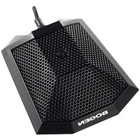
SCU250 - Microphone Bogen - Free user manual and instructions
Find the device manual for free SCU250 Bogen in PDF.


| Product Type | Professional Boundary Microphone |
| Brand | Bogen |
| Model | SCU250 |
| Element Type | Back Electret Condenser |
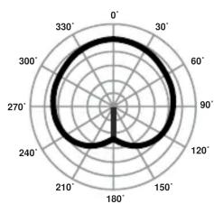
| Polar Pattern | Uni-directional (Cardioid) |
| Frequency Response | 20 Hz - 18 kHz |
| Sensitivity | -58 dB ± 3 dB (0 dB = 1 V/microbar) |
| Maximum SPL | >130 dB at 1% THD |
| Signal-to-Noise Ratio | >65 dB |
| Impedance | 250 ohms |
| Cable Length | 26 ft (approx. 7.9 m) |
| Dimensions (W x H x D) | 2.75 in x 0.75 in x 3.25 in |
| Weight | 1 lb (approx. 0.45 kg) |
| Finish | Matte black |
| Power Requirement | 9V – 52V DC phantom power |
| Output Connector | Male XLR with built-in preamplifier |
| Housing Material | Heavy copper case |
| Mounting | Surface mount with keyways for hanging or attachment |
| Applications | Meeting rooms, conferences, stage productions |
| Warranty | 1 year limited warranty |
Frequently Asked Questions - SCU250 Bogen
User questions about SCU250 Bogen
0 question about this device. Answer the ones you know or ask your own.
Ask a new question about this device
Download the instructions for your Microphone in PDF format for free! Find your manual SCU250 - Bogen and take your electronic device back in hand. On this page are published all the documents necessary for the use of your device. SCU250 by Bogen.
USER MANUAL SCU250 Bogen
Professional Boundary
Microphone
DESCRIPTION
The SCU250 is an unobtrusive, uni-directional, surface-mount microphone ideal for meeting rooms, conferences, and stage productions where minimum visibility is ideal. The SCU250 provides full, rich reproduction of voice and music and is well-suited in capturing the sound source and the immediate surroundings. It has a low sensitivity to stage vibration and thumping noise and has excellent user sound isolation feedback rejection. The SCU250 has a low-impedance balanced output. The SCU250 features a heavy copper case with a non-glare matte black finish, mounting keyways on bottom for hanging or for attachment to the mounting surface, and a cardioid pickup pattern. The microphone requires an external 9V - 52V DC phantom power supply and is terminated by a standard male XLR with a built-in pre-amplifier.
SPECIFICATIONS
MIC Type: Boundary
Element: Back Electret condenser
Polar Pattern: Uni-directional
Impedance: 250-ohm
Frequency Response: 20 Hz to 18 kHz
Sensitivity*: -58 dB +/- 3 dB
Max SPL @ 1% THD: >130 dB
S/N Ratio: >65 dB
Cable: 26 ft.
Dimensions: 2 ^3/4 " W x ^3/4 " H x 3^1/_4 " D
Product Weight: 1 lb.
Finish: Matte black finish
* (0dB=1V/microbar 1,000 Hz indicated by open circuit)

natural_image
Technical line drawing of a mechanical component with checkered pattern and a central cross symbol (no text or labels)FREQUENCY RESPONSE GRAPH

line
| Hz | 0° on axis | 180° off axis | | ---- | ---------- | ------------- | | 20 | -60 | -70 | | 200 | -60 | -75 | | 1K | -60 | -90 | | 2K | -55 | -70 | | 20K | -65 | -85 |POLAR GRAPH
radar
| Angle (°) | Value | |---|---| | 0 | 100 | | 30 | 95 | | 60 | 90 | | 90 | 85 | | 120 | 80 | | 150 | 75 | | 180 | 70 | | 210 | 65 | | 240 | 60 | | 270 | 55 | | 300 | 50 | | 330 | 45 |INSTALLATION
Rather than drill a hole large enough to fit the male XLR, the SCU250 cable can be disconnected from the XLR and then reconnected, thereby permitting an installer to drill a hole only large enough for the cable to fit through.
- Release the shell by unscrewing the shell screw. See Figure 1.
- Pull shell up cable.
- Disconnect the cable by loosening the three terminal strip screws. See Figure 2.
-
Remove shell and strain relief from cable.
-
Drill a 1/8" hole or greater and feed cable through hole.
-
Slide shell and then strain relief back on cable.
-
Reconnect cable to terminal strip following the illustrations in Figures 3 and 4.
-
Slide shell over electronics assembly and replace and tighten the shell screw.
LIMITED WARRANTY
Bogen microphones are warranted to be free from defects in material or workmanship provided that the product has not been subjected to abuse or accident or altered in any way for one (1) year from the date of sale to the original purchaser. Any part of the product covered by this warranty that, with normal installation and use, becomes defective will be repaired or replaced by Bogen, at our option, provided the product is shipped insured and prepaid to: Bogen Factory Service Department, 50 Spring Street, Ramsey, NJ 07446, USA. The product will be returned to you freight prepaid. This warranty does not extend to any of our products that have been subjected to misuse, improper storage, neglect, accident, improper installation or have been modified or repaired in any manner that Bogen believes may affect the reliability of the product, or where the serial number or date code has been removed or defaced.
THE FOREGOING LIMITED WARRANTY IS BOGEN'S SOLE AND EXCLUSIVE WARRANTY AND THE PURCHASER'S SOLE AND EXCLUSIVE REMEDY. BOGEN MAKES NO OTHER WARRANTIES OF ANY KIND, EITHER EXPRESS OR IMPLIED, AND ALL IMPLIED WARRANTIES OF MERCHANTABILITY OR FITNESS FOR A PARTICULAR PURPOSE ARE HEREBY DISCLAIMED AND EXCLUDED. Bogen's liability arising out of the manufacture, sale or supplying of products or their use or disposition, whether based upon warranty, contract, tort or otherwise, shall be limited to the price of the product. In no event shall Bogen be liable for special, incidental or consequential damages (including, but not limited to, loss of profits, loss of data or loss of use damages) arising out of the manufacture, sale or supplying of products, even if Bogen has been advised of the possibility of such damages or losses.
Products that are out of warranty will also be repaired by the Bogen Factory Service Department -- same address as above or call 201-934-8500. The parts and labor involved in these repairs are warranted for 90 days when repaired by the Bogen Factory Service Department. All shipping charges in addition to parts and labor charges will be at the owner's expense.
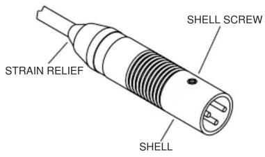
Figure 1.

LOOSEN SCREWS 1, 2 & 3
Figure 2.

INSERT THE WIRES
Figure 3.
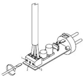
TIGHTEN SCREWS 1, 2 & 3
Figure 4.
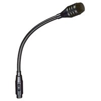

Brand : Bogen
Model : SCU250
Category : Microphone