
HumidiPRO H6062 - Humidifier HONEYWELL - Free user manual and instructions
Find the device manual for free HumidiPRO H6062 HONEYWELL in PDF.


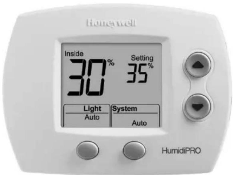
| Product Type | Digital Humidity Controller (Humidistat) |
| Brand | Honeywell |
| Model | HumidiPRO H6062 |
| Power Supply | 24 VAC constant (R and C terminals) |
| Humidity Range (Humidification) | 10 % to 60 % (default), expandable to 90 % |
| Humidity Range (Dehumidification) | 40 % to 80 % (default), expandable to 90 % |
| Operating Ambient Temperature | 0 °C to 48.9 °C (32 °F to 120 °F) |
| Operating Relative Humidity | 5 % to 90 % (non-condensing) |
| Dimensions (approx.) | 10 x 10 x 2.5 cm |
| Weight (approx.) | 0.2 kg |
| Main Functions | Digital humidity control, automatic and manual modes, window protection, outdoor sensor (optional), backlit display |
| Installation | On return duct or remote wall mounting |
| Compatible Outdoor Sensor | C7089 (optional, for automatic mode) |
| Maintenance and Cleaning | Clean the exterior with a soft, dry cloth. Do not use liquids or abrasive products. |
| Safety | Risk of electric shock: cut power before installation. Follow local codes. |
| Spare Parts and Repairability | Outdoor sensor C7089 available. Repairs by a qualified professional. |
| Warranty | 5-year limited (parts and labor) |
Frequently Asked Questions - HumidiPRO H6062 HONEYWELL
User questions about HumidiPRO H6062 HONEYWELL
0 question about this device. Answer the ones you know or ask your own.
Ask a new question about this device
Download the instructions for your Humidifier in PDF format for free! Find your manual HumidiPRO H6062 - HONEYWELL and take your electronic device back in hand. On this page are published all the documents necessary for the use of your device. HumidiPRO H6062 by HONEYWELL.
USER MANUAL HumidiPRO H6062 HONEYWELL
Honeywell
Installation Instructions
HumidiPRO H6062 Digital Humidity Control
When Installing this Product
Read these instructions carefully, failure to follow them could damage the product and cause a hazardous situation.
Check the ratings given in the instructions and on the product to make sure the product is suitable for your application
Installer must be a trained, experienced service technician.
After installation is complete, check out product operation as provided in these instructions.
Cautions
Electrical shock or equipment damage may occur.
Disconnect power supply before beginning installation.
Duct Installation (recommended) OR
- Choose a location on the RETURN duct.

flowchart
graph TD
    A["RETURN AIR"] --> B["ALTERNATE LOCATION"]
    B --> C["RETURN AIR"]
    C --> D["6 IN (152 MM) MINIMUM"]
    D --> E["BEST LOCATION"]
    E --> F["RETURN AIR DUCT"]
    F --> G["15 IN (381 MM) MINIMUM"]
    G --> H["M34579"]
Warning: Product must be mounted on the RETURN side of the duct for proper RH% sensing.
Remote Mount Installation
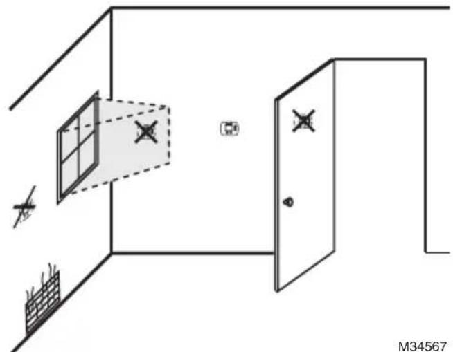
- Choose a location in the living area.
NOTE: Select a location clear of drafts or excessive humidity. Avoid mounting near doors or windows, or in bathrooms or kitchens.
natural_image
Diagram of a room layout with window, door, and wall markers (no text or symbols)Duct-Mount Installation
- Separate wallplate from humidistat.

Caution: Electrical Hazard
Can cause electrical shock or equipment damage. Disconnect power before beginning installation.
- Mark the duct-tube hole.

natural_image
Line drawing of a hand holding a pen to draw a square button on a device panel (no text or symbols)Hold the wallplate up to the desired location on the duct and make a mark inside the duct tube hole.
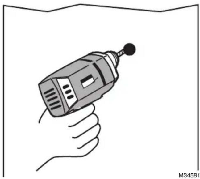
- Drill the duct-tube hole.
natural_image
Illustration of a hand holding a handheld electric drill bit (no text or symbols)Find your mark and drill a 1/2 in. hole in the duct. This is where the duct tube will be inserted to capture air.
- Insert the duct tube.
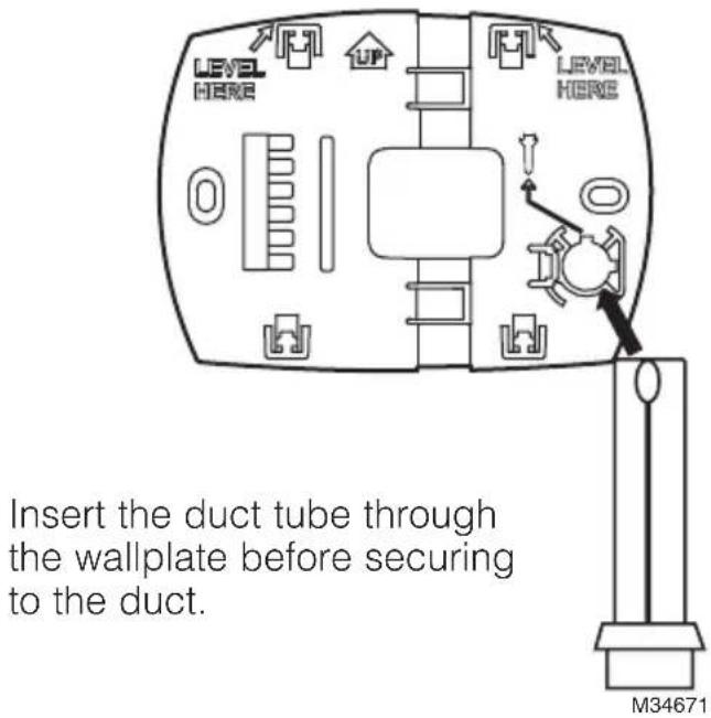
- Secure the wallplate.

natural_image
Technical diagram of a mechanical component with bolts and a central square, enclosed in a rectangular frame (no text or symbols)Secure the wallplate to the duct with sheet metal screws (provided).
- Run wires through the back plate.

Run wires through the top or bottom channel on the back plate when duct-mounted. If installing like a thermostat on a wall, run the wires through the back.
Wiring the Humidistat
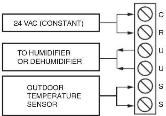
This humidity control is wired the same way a manual humidistat (H8908) is wired. The only difference is that you also wire in power (24 VAC) and an outdoor sensor.
TERMINAL DESIGNATION
C 24 VAC POWER FROM EQUIPMENT
R 24 VAC POWER FROM EQUIPMENT
U HUMIDIFIER/DEHUMIDIFIER
U HUMIDIFIER/DEHUMIDIFIER
S OUTDOOR SENSOR
S OUTDOOR SENSOR
flowchart
graph TD
    A["24 VAC (CONSTANT)"] --> B["C"]
    A --> C["R"]
    D["TO HUMIDIFIER OR DEHUMIDIFIER"] --> E["U"]
    D --> F["S"]
    G["OUTDOOR TEMPERATURE SENSOR"] --> H["S"]
NOTES: C AND R MUST BE CONSTANT 24VAC! RECOMMENDED TO WIRE TO FURNACE/AIR HANDLER CONTROL BOARD.
DO NOT WIRE C AND R TO HUMIDIFIER TRANSFORMER!
M34569
Wiring HumidiPRO with Fan Interlock

flowchart
graph TD
    L1["POWER SUPPLY"] --> FAN_CONTROL["FAN CONTROL"]
    L2["1"] --> FURNACE["FUNNACE FAN MOTOR"]
    FAN_CONTROL --> TRANSFORMER["TRANSFORMER"]
    TRANSFORMER --> HUMIDIFIER["HUMIDIFIER"]
    HUMIDIFIER --> OUTDOOR["Sensor"]
    OUTDOOR --> C["C"]
    OUTDOOR --> R["R"]
    OUTDOOR --> U["U"]
    OUTDOOR --> S["S"]
    OUTDOOR --> S["S"]
    C --> 24VAC["24 VAC (CONSTANT)"]
    R --> 24VAC
    U --> 24VAC
    S --> 24VAC
    S --> 24VAC
    style L1 fill:#f9f,stroke:#333
    style L2 fill:#f9f,stroke:#333
    style FAN_CONTROL fill:#ccf,stroke:#333
    style TRANSFORMER fill:#ccf,stroke:#333
    style HUMIDIFIER fill:#cfc,stroke:#333
    style OUTDOOR fill:#fcc,stroke:#333
    note right of L1: PROVIDE DISCONNECT MEANS AND OVERLOAD PROTECTION AS REQUIRED.
    note right of L2: 24 VAC WIRING.
    M34570 at bottom right
Wiring HumidiPRO with Fan Interlock for 2 Speed Motor

flowchart
graph TD
    L1["(HOT)"] --> POWER["SUPPLY"]
    L2["1"] --> POWER
    POWER --> FAN_CONTROL["FAN CONTROL"]
    FAN_CONTROL --> TRANSFORMER["TRANSFORMER"]
    TRANSFORMER --> C["R"]
    TRANSFORMER --> U["U"]
    TRANSFORMER --> S["S"]
    TRANSFORMER --> OUTDOODS["OUTDOOR SENSOR"]
    DPST["DPST SWITCHING RELAY"] --> H["H"]
    DPST --> L["L"]
    DPST --> C["C"]
    H --> 2-SPEED["FAN MOTOR"]
    L --> 2-SPEED
    2-SPEED --> H
    2-SPEED --> C
    style 2-SPEED fill:#f9f,stroke:#333
    style_2-VACWING["24 VAC WIRING"] fill:#ccf,stroke:#333
    style H fill:#cfc,stroke:#333
    style L fill:#cfc,stroke:#333
    style C fill:#cfc,stroke:#333
    style H fill:#fcc,stroke:#333
    style L fill:#fcc,stroke:#333
    style C fill:#fcc,stroke:#333
    style OUTDOODS fill:#fff,stroke:#333
    note right of H: PROVIDE DISCONNECT MEANS AND OVERLOAD PROTECTION AS REQUIRED.
    note right of L2: 24 VAC WIRING.
    note right of M34571
Wiring HumidiPRO with Current Sensing Relay

flowchart
graph TD
    A["OUTDOOR SENSOR"] --> B["C 24 VAC (CONSTANT)"]
    A --> C["R U S S"]
    A --> D["L2 L1 (HOT)"]
    A --> E["HUMIDIFIER"]
    F["CURRENT SENSING RELAY"] --> G["LO"]
    G --> H["HI"]
    H --> I["L2"]
    I --> J["L1 (HOT)"]
    J --> K["HUMIDIFIER"]
1 PROVIDE DISCONNECT MEANS AND OVERLOAD PROTECTION AS REQUIRED.
M34572
Wiring HumidiPRO with Sail/Pressure Switch
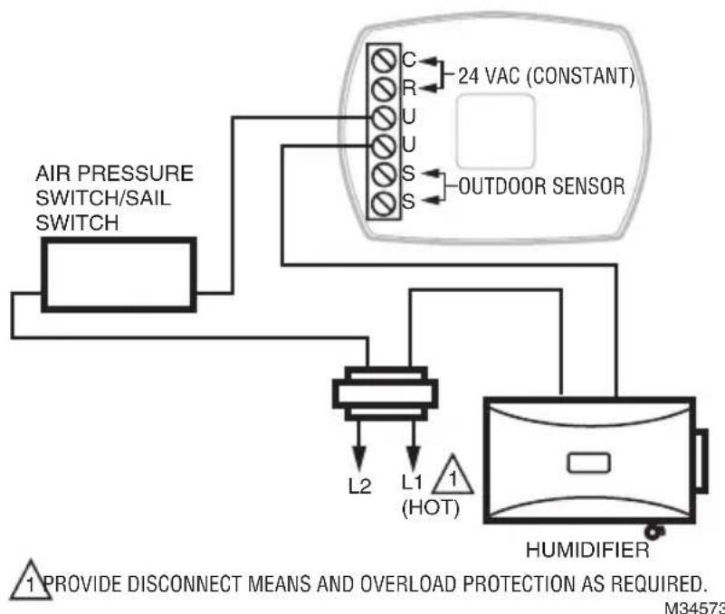
flowchart
graph TD
    A["AIR PRESSURE SWITCH/SAIL SWITCH"] --> B["24 VAC (CONSTANT)"]
    B --> C["OUTDOOR SENSOR"]
    C --> D["HUMIDIFIER"]
    D --> E["L1 (HOT)"]
    E --> F["L2"]
    F --> G["1 PROVIDE DISCONNECT MEANS AND OVERLOAD PROTECTION AS REQUIRED. M34573"]
Wiring HumidiPRO to FORCE FAN ON (Basic Humidifier)

NOTES: USE DPST RELAY FOR HUMIDITY ON DEMAND WITH A BASIC HUMIDIFIER.
HUMIDIFIER MUST BE PLUMBED TO HOT WATER WHEN FORCING FAN.
HONEYWELL ADVANCED HUMIDIFIERS DO NOT NEED A RELAY TO FORCE FAN.
M34574
Wiring HumidiPRO to TrueEASE Advanced Humidifier with Fan Interlock (HE150/HE250/HE300)

flowchart
graph TD
    A["Monitor System Call for Fan"] -->|Off| B["HVAC"]
    A -->|On| C["GYWR C"]
    D["THERMOSTAT G "FAN""] --> E["Equipment"]
    F["24VAC CONSTANT"] --> G["Power IN (24 Vac)"]
    H["POWER IN NOT REQUIRED ON HE300"] --> I["Sensor (Airflow)"]
    J["HUM CONTROL"] --> K["POWER OUT (24 Vac)"]
    L["HumidiPRO"] --> M["Outdoor Sensor"]
    N["Gf R Gt or W"] --> K
    O["C"] --> K
NOTE: SEE TrueEASE INSTALL GUIDE FOR DETAILED WIRING INFORMATION.
M34577
Wiring HumidiPRO to TrueSTEAM Advanced Humidifier


NOTE: SEE TrueSTEAM INSTALL GUIDE FOR DETAILED WIRING INFORMATION.
M34576
Wiring HumidiPRO to Dehumidifier

Mounting the Outdoor Sensor
(Not required if window protection isn't needed)
Location
Mount the sensor where:
- it cannot be tampered with.
• there is good air circulation. - surface is flat.
• wire distance between sensor and humidistat is less than 200 feet. - it can measure true outdoor ambient temperature.
Do NOT mount the sensor:
- in direct sunlight.
• where snow, ice or debris can cover it. - where hot or cold air blows on the sensor. (For example, a discharge line from an outdoor compressor unit, vent or fan can cause inaccurate temperature readings.)
Steps to mount the sensor
- Remove the sensor from the mounting clip.
- Mark the area on the location selected for mounting the sensor mounting clip.
- Mount the clip. Image on right shows typical locations for outdoor sensor.

natural_image
Diagram showing a window frame with an inset magnified view of a wall-mounted fixture (no text or symbols present)M7514A
Wiring the sensor
Caution
Electrical Interference (Noise) Hazard. Can cause erratic system operation.
- Keep wiring at least one foot away from large inductive loads such as motors, line starters, lighting ballasts and large power distribution panels.
Use shielded cable to reduce interference when rerouting is not possible. - Be sure wires have a cable separate from the thermostat cable.
- Do not route temperature sensor wiring with building power wiring, next to control contactors or near light dimming circuits, electric motors or welding equipment.
- Avoid poor wiring connections.
- Avoid intermittent or missing building earth ground.
Caution
Electrical Shock Hazard. Can cause electrical shock or equipment damage.
Disconnect power supply before connecting wiring.
Wiring must comply with applicable codes, ordinances and regulations:
-
Wire the C7089 Outdoor Sensor to the S terminals on the humidity control. If leadwire provided with C7089 is not long enough (60 in.), run a cable to a hole at C7089 location.
-
Using color-coded, 18-gauge, shielded thermostat wire is recommended. For example of general wiring of C7089, see image at right.
• Pigtail wiring can be used. -
Mount C7089 in its mounting clip.
- Plug wiring hole using nonhardening caulk or putty.


USE APPROPRIATE MOUNTING MEANS FOR THE TYPE OF STRUCTURE.

PLUG WIRING HOLE WITH NON-HARDENING CAULK OR PUTTY.
M34611
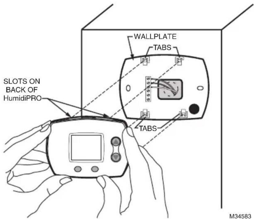
Mount Humidity Control
Align the 4 tabs on the wallplate with the slots on the back of the control, then push gently until the control snaps in place.
Checkout
Allow C7089B Outdoor Sensor to absorb outdoor air for a minimum of twenty minutes before taking a reading.
With an accurate thermometer ( ±1ircF [0.5°C]), measure the temperature at the sensor location, allowing time for the thermometer to stabilize before reading.
Then verify the sensor accuracy by going into installer Test #20. This will show you the outdoor temperature.
Calibration
The C7089 Outdoor Sensor is calibrated at the factory. However, you can offset the outdoor sensor reading using Function 35 in Installer Setup.
You've just installed your Humidity Controller!
This Humidity Control has been preprogrammed to the ideal settings for most homes.
If you installed this control with an outdoor sensor, the control will operate in AUTOMATIC MODE, which automatically adjusts humidity to help prevent window condensation.
If you installed this control without an outdoor sensor, the control will operate in MANUAL MODE, giving the homeowner simple, direct control of their humidifier (RH% Setting Only).
Advanced Installer Setup
See next page to customize feature operation.
Installer System Test
If Advanced Installer Setup is not required, skip to "Installer System Test/Checkout" on page 27.
Advanced Installer Setup
Honeywell has already programmed this control to work properly in most applications. However, you can adjust the advanced settings by following the steps below.

natural_image
Illustration of a digital device with two finger buttons and a screen, no text or symbols presentTo begin, press and hold the ▲ and LIGHT buttons until the display changes.

M29387A
Press ▲ or ▼ to change settings.
Press NEXT to advance to the next function.
Press DONE to exit and save settings.
| Function Number | Setting | |
| Displayed | Description | |
| 1 System Type | 1 Humidifier | |
| 2 Dehumidifier | ||
| 4 Control ModeAutomatic Mode is Default when Outdoor Sensor DetectedManual Mode is Default when NO Outdoor Sensor Detected | 1 Automatic | |
| 2 Manual | ||
| 5 Automatic Mode RH% (Hum)This is the humidity setpoint (RH%) the control will operate to.The homeowner does not change this and will only need to setthe appropriate window protection setting. | Range: 20%-60%Default = 35% | |
| 11 Automatic Mode Humidity BoostIncreases Preset RH% (#5) when user sets window protectionto 11. | 0 OFF | |
| 5% 5% | ||
| 10% 10% | ||
| 17 Automatic Mode High Temp Shut-OffTurns humidifier OFF when Outdoor Temperature is greaterthan selected setting. | Range: 40° - 90°0 = OFFDefault = 65° | |
| 19 High Hum Limit | Range: 10% - 90%Default = 60% | |
| 20 Low Hum Limit | Range: 10% - 90%Default = 10% | |
| 21 High Dehum Limit | Range: 10% - 90%Default = 80% | |
| 23 Low Dehum Limit | Range: 10% - 90%Default = 40% | |
| 25 Dehumidifier Compressor Lockout | 0 - 5 MinutesDefault = 0 Minutes(OFF) | |
| 30 Humidity Sensing CalibrationThis feature will offset the sensed indoor humidity. | Range: -9% to +9%Default = 0 (Displays Actual RH%) | |
| 35 Outdoor Temperature Sensor CalibrationThis feature will offset the sensed outdoor temperature if needed. | Range: -9° to +9°Default = 0 (Displays Actual Outdoor Temp) | |
Honeywell HumidiPRO™ Frost Index
| Outdoor Temp | |||||||||||||
| -10°F 0°F | 10°F 20°F 30°F 40°F | ||||||||||||
| Frost Index | 1 | 10 | 10 | 10 | 10 | 11 | 11 | 17 | 17 | 25 | 25 | 35 | 36 |
| 2 | 10 | 10 | 10 | 10 | 15 | 15 | 21 | 21 | 29 | 29 | 35 | 39 | |
| 3 | 10 | 10 | 14 | 14 | 19 | 19 | 26 | 26 | 34 | 34 | 35 | 46 | |
| 4 | 15 | 15 | 19 | 19 | 25 | 25 | 32 | 32 | 35 | 39 | 35 | 52 | |
| 5 | 21 | 21 | 26 | 26 | 32 | 32 | 35 | 38 | 35 | 48 | 35 | 58 | |
| 6 | 29 | 29 | 34 | 34 | 35 | 39 | 35 | 48 | 35 | 56 | 35 | 60 | |
| 7 | 35 | 39 | 35 | 46 | 35 | 52 | 35 | 58 | 35 | 60 | 35 | 60 | |
| 8* | 35 | 56 | 35 | 60 | 35 | 60 | 35 | 60 | 35 | 60 | 35 | 60 | |
| 9 | 35 | 60 | 35 | 60 | 35 | 60 | 35 | 60 | 35 | 60 | 35 | 60 | |
| 10 | 35 | 60 | 35 | 60 | 35 | 60 | 35 | 60 | 35 | 60 | 35 | 60 | |
*Black Numbers show highest humidity allowed when Default RH% (35%) is Selected.
Note: Smaller grey numbers show highest humidity allowed when Maximum RH% (60%) is selected.
Installer System Test/Checkout
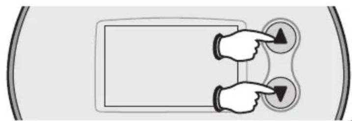
natural_image
Diagram showing two hands pointing at three circular buttons with arrows, no text or symbols presentTo begin, press and hold the ▲ and ▼ buttons until the display changes.
Test number System status

Press ▲ / ▼ to turn system on/off. Press NEXT to advance to next test. Press DONE to terminate system test.
| Function Number | Setting | |
| Number Description | Description | |
| 10 System Test | 0 OFF | |
| 1 ON | ||
| 20 View Outdoor Temperature | Shows Outdoor Temperature | |
Installer System Test/Checkout (continued)
NOTE: Most humidifiers require airflow in the system to operate. Make sure to turn on the system fan when testing humidifier operation.
Caution: If running a dehumidifier, compressor protection is bypassed during testing; avoid cycling the compressor too quickly.
Note: Some dehumidifiers may already have built in compressor protection.
Specifications
Humidity Ranges:
Humidify:
• Default: 10% to 60%
• Total Range Available: 10% to 90%
Dehumidify:
• Default: 40% to 80%
• Total Range Available: 10% to 90%
Operating Ambient Temperature
• 32° to 120°F (0° to 48.9°C)
Operating Relative Humidity
• 5% to 90% (non-condensing)
Troubleshooting
If you have difficulty with your humidity control, please try the following suggestions. Most problems can be corrected quickly and easily.
Display is blank
- Check circuit breaker and reset if necessary.
- Check for 24VAC between R and C at the wall plate.
• Make sure power switch at heating and cooling system is on.
• Make sure furnace door is closed securely.
Humidity settings do not change
Make sure the humidity is set to an acceptable range:
- Check current range stop settings in Installer Setup.
• Auto Mode: 1–10 (up to 11 if Humidity Boost is enabled)
• Manual Mode: 20%–60%
• Dehumidification Mode: 40%–80%
Troubleshooting (continued)
Humidifier/Dehumidifier will not turn on
• Make sure the equipment fan is running.
• Make sure System Setting is ON.
- Make sure there is power going to the Humidifier or Dehumidifier.
- Check the humidity table to see if Window Protection is preventing a call for humidity. (Auto Humidification Mode Only).
- Check whether Compressor Lockout is enabled.
- Check whether High Temperature Shut-off is enabled (ISU-17) and Outdoor Temperature is less than selected Shut-off Temperature.
Customer Assistance
For assistance with this product, please visit yourhome.honeywell.com.
Or call Honeywell Customer Care toll-free at 1-800-468-1502.
Five-Year Limited Warranty
Honeywell warrants this product, excluding lamps, to be free from defects in the workmanship or materials, under normal use and service, for a period of five (5) years from the date of purchase by the consumer. If, at any time during the warranty period, the product is defective or malfunctions, Honeywell shall repair or replace it (at Honeywell's option) within a reasonable period of time. If the product is defective, (i) return it, with a bill of sale or other dated proof of purchase, to the retailer from which you purchased it, or (ii) package it carefully, along with proof of purchase (including date of purchase) and a short description of the malfunction, and mail it, postage prepaid, to the following address: Honeywell Return Goods, Dock 4 MN10-3860, 1885 Douglas Dr. N, Golden Valley, MN 55422.
This warranty does not cover removal or reinstallation costs. This warranty shall not apply if it is shown by Honeywell that the defect or malfunction was caused by damage which occurred while the product was in the possession of a consumer.
Honeywell's sole responsibility shall be to repair or replace the product within the terms stated above. HONEYWELL SHALL NOT BE LIABLE FOR ANY LOSS OR DAMAGE OF ANY KIND, INCLUDING ANY INCIDENTAL OR CONSEQUENTIAL DAMAGES RESULTING, DIRECTLY OR INDIRECTLY, FROM ANY EACH OF ANY WARRANTY, EXPRESS OR IMPLIED, OR ANY OTHER FAILURE OF THIS PRODUCT. Some states do not allow the exclusion or limitation of incidental or consequential damages, so this limitation may not apply to you.
THIS WARRANTY IS THE ONLY EXPRESS WARRANTY HONEYWELL MAKES ON THIS PRODUCT. THE DURATION OF ANY IMPLIED WARRANTIES, INCLUDING THE WARRANTIES OF MERCHANTABILITY AND FITNESS FOR A PARTICULAR PURPOSE, IS HEREBY LIMITED TO THE FIVE YEAR DURATION OF THIS WARRANTY. Some states do not allow limitations on how long
an implied warranty lasts, so the above limitation may not apply to you. This warranty gives you specific legal rights, and you may have other rights which vary from state to state. If you have any questions concerning this warranty, please write Honeywell Customer Relations, Honeywell, 1985 Douglas Dr. N MN10-1461, Golden Valley, MN 55422.
Honeywell
Automation and Control Solutions
Honeywell International Inc.
1985 Douglas Drive North
Golden Valley, MN 55422
yourhome.honeywell.com
® U.S. Registered Trademark
© 2013 Honeywell International Inc.
69-2794EFS—03 M.S. Rev. 05-13
Printed in United States

69-2794EFS-03
Honeywell
natural_image
Diagram showing a room with a window, door, and wall-mounted fixtures (no text or symbols)Installation en gaine
natural_image
Line drawing of a hand holding a pen to draw a square button on a device panel (no text or symbols)natural_image
Illustration of a hand holding a handheld electric drill bit (no text or symbols)natural_image
Technical diagram of a mechanical assembly with bolts, screw, and a central component (no text or symbols)natural_image
Diagram showing a window frame with an inset magnified view of a wall-mounted fixture (no text or symbols present)M7514A
natural_image
Illustration of a digital device with two buttons and a screen, no text or symbols presentHoneywell International Inc.
1985 Douglas Drive North
Golden Valley, MN 55422
yourhome.honeywell.com
© 2013 Honeywell International Inc.
69-2794EFS—03 M.S. Rev. 05-13
69-2794EFS-03
Honeywell
natural_image
Diagram showing a room layout with a window, door, and wall-mounted fixtures (no text or symbols)natural_image
Line drawing of a hand holding a pen to draw a button on a device panel (no text or symbols)natural_image
Illustration of a hand holding a handheld electric drill bit (no text or symbols)natural_image
Technical diagram of a mechanical component with screws, bolts, and a central square (no text or symbols)natural_image
Diagram showing a window frame with an inset magnified view of a wall-mounted fixture (no text or symbols)M7514A
Cableado del sensor
Precaución
natural_image
Illustration of a digital device with two buttons and a screen, no text or symbols presentyourhome.honeywell.com.
Honeywell International Inc.
1985 Douglas Drive North
Golden Valley, MN 55422
yourhome.honeywell.com
69-2794EFS—03 M.S. Rev. 05-13
69-2794EFS-03


- Honeywell
- Installation Instructions
- HumidiPRO H6062 Digital Humidity Control
- When Installing this Product
- Cautions
- Duct Installation (recommended) OR
- Remote Mount Installation
- Duct-Mount Installation
- Caution: Electrical Hazard
- Wiring the Humidistat
- Wiring HumidiPRO with Fan Interlock
- Wiring HumidiPRO with Current Sensing Relay
- Wiring HumidiPRO with Sail/Pressure Switch
- Wiring HumidiPRO to FORCE FAN ON (Basic Humidifier)
- Wiring HumidiPRO to TrueEASE Advanced Humidifier with Fan Interlock (HE150/HE250/HE300)
- Wiring HumidiPRO to TrueSTEAM Advanced Humidifier
- Wiring HumidiPRO to Dehumidifier
- Mounting the Outdoor Sensor
- Location
- Steps to mount the sensor
- Caution
- Electrical Interference (Noise) Hazard. Can cause erratic system operation.
- Electrical Shock Hazard. Can cause electrical shock or equipment damage.
- Mount Humidity Control
- Checkout
- Calibration
- You've just installed your Humidity Controller!
- Advanced Installer Setup
- Installer System Test
- Installer System Test/Checkout
- Installer System Test/Checkout (continued)
- Caution: If running a dehumidifier, compressor protection is bypassed during testing; avoid cycling the compressor too quickly.
- Specifications
- Troubleshooting
- Display is blank
- Humidity settings do not change
- Troubleshooting (continued)
- Humidifier/Dehumidifier will not turn on
- Customer Assistance
- Five-Year Limited Warranty
- Automation and Control Solutions
- Installation en gaine
- Precaución
- yourhome.honeywell.com.
Brand : HONEYWELL
Model : HumidiPRO H6062
Category : Humidifier