
FIVBDP10A - Power inverter Furrion - Free user manual and instructions
Find the device manual for free FIVBDP10A Furrion in PDF.


| Product Type | 1000W Pure Sine Wave Inverter |
| Brand | Furrion |
| Model | FIVBDP10A |
| Dimensions (L x W x H) | 435 x 236 x 112 mm |
| Net Weight | 5.05 kg |
| Gross Weight | 5.5 kg |
| DC Input Voltage | 10.5 V ~ 15 V DC |
| AC Output Voltage | 115 ± 5 V AC |
| Output Frequency | 60 ± 1 Hz |
| Continuous Power Rating | 1000 W |
| Peak Power (2 s) | 2500 W |
| Output Waveform | Pure Sine Wave |
| Maximum Efficiency | 88% |
| Bypass AC Input | 100 ~ 120 V AC |
| Circuit Breaker | 15 A |
| Bypass Transfer Time | < 20 ms |
| Protections | Overheating, battery under/over voltage, overload, short circuit |
| Reverse Polarity Protection | Yes (by fuse) |
| Operating Temperature | 0 °C ~ 40 °C |
| Operating Humidity | < 90% RH (non-condensing) |
| Maintenance and Cleaning | Clean with a dry cloth; do not use chemicals |
| Spare Parts and Repairability | Internal fuse not user-replaceable; contact a technician |
| Warranty | 1 year limited |
| Safety Standards | ETL listed to UL 458 and CSA C22.2 No. 107.1 |
| EMC Compliance | Complies with FCC Part 15 Class B |
Frequently Asked Questions - FIVBDP10A Furrion
User questions about FIVBDP10A Furrion
0 question about this device. Answer the ones you know or ask your own.
Ask a new question about this device
Download the instructions for your Power inverter in PDF format for free! Find your manual FIVBDP10A - Furrion and take your electronic device back in hand. On this page are published all the documents necessary for the use of your device. FIVBDP10A by Furrion.
USER MANUAL FIVBDP10A Furrion
natural_image
Exterior view of a black industrial power supply unit with attached cable and ventilation slots (no visible text or symbols)Welcome
Thank you and congratulations for purchasing this Furrion® 1000W Pure Sine Wave Power Inverter. Before operating your new product, please read these instructions carefully. This instruction manual contains information for safe use, installation and maintenance of the product.
Please keep this instruction manual in a safe place for future reference. This will ensure safe use and reduce the risk of injury. Be sure to pass on this manual to new owners of this product.
The manufacturer does not accept responsibility for any damages as a result of not following these instructions.
If you have any further questions regarding our products, please contact us at support@furrion.com
Contents
Welcome....1
Contents 2
Important Safety Instructions....3
General Safety Precautions 3
Precautions When Working with Batteries....3
About your Product....4
Product Features....4
Protective Features of the Inverter 4
How your Inverter Works 4
Product Overview ....5
Front Panel....5
Rear Panel....5
Installation 6
What's in the Box 6
Mounting the Inverter 6
Connecting to a Load 7
Connecting to a Power Source....9
Operation....10
Care and Maintenance ....11
Fuse Replacement .... 1
Disposal of your Old Product and Batteries 1
Specifications 12
Troubleshooting....13
Warranty....14
Important Safety Instructions

WARNING
- Before using the Inverter, read and save the safety instructions.
IMPORTANT: THIS MANUAL CONTAINS IMPORTANT INFORMATION REGARDING SAFETY, OPERATION, MAINTENANCE AND STORAGE OF THIS PRODUCT. BEFORE USE, READ AND UNDERSTAND ALL CAUTIONS, WARNINGS, INSTRUCTIONS AND PRODUCTION LABELS, PLUS YOUR VEHICLE'S BATTERY MANUFACTURER GUIDELINES. FAILURE TO DO SO COULD RESULT IN INJURY AND/OR PROPERTY DAMAGE.
General Safety Precautions
- Do not expose the Inverter to rain, snow, spray, bilge or dust. To reduce risk of hazard, do not cover or obstruct the ventilation openings. Do not install the Inverter in a zero-clearance compartment. Overheating may result.
- To avoid a risk of fire and electronic shock. Make sure the existing wiring is in good electrical condition, and the wire size is not undersized.
- This equipment contains components which can produce arcs or sparks. To prevent fire or explosion do not install in compartments containing batteries or flammable materials or in locations which require ignition protected equipment. This includes any space containing gasoline-powered machinery, fuel tanks, joints, fittings, or other connection between components of the fuel system.
- Make sure the wires equipped are in good electrical condition. Do not operate the inverter with wires punctured or damaged.
- This is not a toy, keep away from children.
Precautions When Working with Batteries
- If battery acid contacts skin or clothing, wash immediately with soap and water. If acid enters eye, immediately flood eye with running cold water for at least 20 minutes and get medical attention immediately.
- Never smoke or allow a spark or flame in vicinity of battery.
- Do not let metal come in contact with the top of the battery. The resulting spark or short-circuit may cause an explosion.
About your Product
Product Features
- 1000 Watt continuous output for electronic appliances
• High surge power up to 2500W - Pure sine wave output to operate higher-end electronic equipment
- Built in transfer switch with less than 20ms transfer time.
• Built in advance microprocessor - Hard wire AC connection
• LED indicator with all operation status - Low standby current
Protective Features of the Inverter
OVER TEMPERATURE PROTECTION – If the temperature inside the inverter is too high, the unit will automatically shut down. The inverter will automatically restart after the temperature inside recovers to normal.
LOW BATTERY VOLTAGE PROTECTION - This condition is not harmful to the inverter but could damage the power source. The inverter automatically shuts down when input voltage drops to 10.5 volts.
OVER VOLTAGE PROTECTION – The inverter will automatically shut down when the input voltage exceeds 15.3 volts DC. Input voltage exceeding 16 volts could damage the inverter.
OVERLOAD PROTECTION – The inverter will automatically shut down when the continuous draw exceeds rated watts.
SHORT CIRCUIT PROTECTION – The inverter will shut down. Remove the short circuit and restart inverter.
How your Inverter Works
The Furrion power inverter is an electronic product that has been designed and built to take low voltage DC (Direct Current) power from your automobile or other low voltage power supplies and convert it to standard 115 Volt AC (Alternating Current) power similar to the current you have in your home. This conversion allows you to use many of your household appliances and electronic products in automobiles, RVs, boats, tractors, trucks and etc..
Product Overview
Front Panel

Rear Panel

Installation
What's in the Box
Make sure you have all the following items included in the packaging. If any item is damaged or missing, contact your dealer.
- Power Inverter x 1
- Instruction Manual x 1
- Warranty Card x 1
Mounting the Inverter
The inverter has four slots in its mounting bracket that allows the unit to be fastened against a bulkhead, floor, wall or other flat surface. (Fig. 1)

natural_image
Technical line drawing of an electronic device with ports and connectors, labeled as Fig. 1 (no text or symbols on the device itself)The inverter can be operated in any position, however, if it is to be mounted on a wall, mount it horizontally (see Fig. 2 for correct mounting direction) so that indicators, switches, outlets and terminal blocks located on the front panel are visible and accessible. If inverter is to be installed in a moving vehicle, it is strongly recommended that the inverter be shock-mounted either on the floor (in a clear, safe area) or on a secure flat surface.

Fig. 2
The power inverter should be installed in an environment that meets the following requirements.
- DRY – Do not allow water to drip on or enter into the inverter.
- COOL - Ambient air temperature should be between 0°C and 40°C, the cooler the better.
- SAFE – Do not install the inverter in a battery compartment or other areas where volatile fumes may exist, such as fuel storage areas or engine compartments.
- VENTILATED – Keep the inverter (25mm at least) away from surrounding objects. Ensure the ventilation area of the unit is not obstructed.
- DUST – Do not install the Inverter in dusty environments. The dust can be inhaled into the unit when the cooling fan is working.
- FUSED – A fuse must be applied between the battery and the Inverter.
- CLOSE TO BATTERIES – Avoid excessive cable lengths. Do not install the Inverter in the same compartment as batteries.
- Use the recommended wire lengths and sizes.
- Do not mount the Inverter where it will be exposed to the gases produced by the battery. These gases are very corrosive, and prolonged exposure will damage the Inverter.
Installation
Connecting to a Load

WARNING
SHOCK HAZARD!
Before proceeding further, carefully check that the Inverter is NOT connected to any batteries, and that all wiring is disconnected from any electrical sources. Make sure the bypass AC input plug is disconnected to any AC source. Do not connect the output terminals of the Inverter to an incoming AC source. Make sure the power switch is in off position before and after the installation.
Neutral Grounding:
The neutral conductor of the AC output circuit of the inverter is automatically connected to the safety ground during inverter operation. This conforms to National Electrical Code requirements that a derived AC source, such as an inverter or generator, must have their neutral conductors tied to ground in the same way that the neutral conductor from the utility is tied to ground at the AC breaker panel. When AC utility power is present and the inverter is in bypass mode, this neutral to ground connection is not present. The utility power neutral is only connected to ground at the breaker panel.
Ground Fault Circuit Interrupters (GFCI):
Recreational Vehicles Installations (for North American approvals) will require GFCI protection. All branch circuits connected to the AC output hard wire should be GFCI protected. Additional electrical codes may require GFCI protection of certain receptacles in residential installations. While the pure sine wave output of the inverter is equivalent to the waveform provided by utilities, compliance with
UL standards requires Furrion to test and recommend specific GFCI. Use only GENERAL PROTECT GROUP INC, Type DG15 ground-fault circuit-interrupter receptacles. Or AMERICAN ELECTRIC DEPOT INC, Type G1501 ground-fault circuit-interrupter receptacles. Other types may fail to operate properly when connected to this unit.
Hard-wire Installation
The AC wiring compartment is located on the front panel of the inverter.
- Remove the AC wiring compartment cover to gain access to the AC output hard-wire (pigtails leads). (Fig. 3)

natural_image
Diagram of a computer power adapter with ventilation slots and an external switch, labeled Fig. 3 (no text or symbols on the diagram itself)- Remove the metal wire clip from the cover. (Fig. 4)

natural_image
Mechanical assembly diagram showing a bracket with mounting holes and two cylindrical components (no text or symbols)Installation
- Connect the AC output wiring to the inverter AC output hard-wire (pigtails leads) by using wire connectors. Black to black, white to white. (Fig. 5)

natural_image
Diagram of a computer power adapter with cable and socket, showing internal components and wiring (no text or symbols)| AC Output Wiring | Wire Length/Gauge | |
| Line (L) Black | Within 25 feet / AWG# 14~16 | |
| Neutral (N) White | ||
| Ground | Green or Bare copper | |
-
Double check all connections to make sure the wires are in correct position and all wires are secured.
-
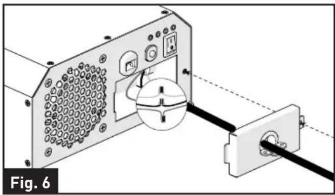
Wrap the wires and place into the compartment. Replace the cover to the inverter and secure with the screw provided. (Fig. 6)
natural_image
Diagram of a computer monitor with an attached cable, showing internal components and wiring (no text or symbols)- Replace the wire clip and fix with 2 screws provided. (Fig. 7)

natural_image
Diagram of a device with labeled components and wiring, showing no readable text or symbols.- Using a 5/32'' hex wrench, loosen the ground lug screw located on the mid left side of the rear panel. Insert an 8AWG copper wire from this lug to chassis ground. Tighten the lug securely with 35inch-lbs torque maximum. (Fig. 8)

Installation
Connecting to a Power Source

CAUTION
- The power inverter must be connected only to batteries with a nominal output voltage of 12volts. The unit will not operate from a 6 volt battery, and will sustain permanent damage if connected to a 24 volt battery.
- The input current of this inverter is about 100A with full load, make sure the battery could discharge over 100A continuously.
- The battery should have a Cold Cranking Amp more than 500A.

CAUTION
Loose connectors may cause overheated wires and melted insulation. Check to make sure you have not reversed the polarity. Reverse polarity connection will result in a blown fuse and may cause permanent damage to the inverter. Damage due to reverse polarity is not covered by warranty.

WARNING
The installation of a fuse must be on the positive cable. Failure to place a fuse on "+" cables running between the Inverter and battery may cause damage to the inverter and will void warranty.
Furrion recommends the following cables for an optimum inverter performance.
External FUSE and DC Cable Selection
| Wire AWG | Capacity of the fuse | Max distance between inverter and the battery |
| #4 150A | 10FT |
The following recommendations should always be followed while making connection between the battery and the Inverter.
- The cables should be made of high quality copper wiring, also keep the cable length as short as possible.
- Cables should be of adequate gauge for the length. The inverter performance will decrease if the cables are not of adequate gauge (too small or too long).
- Battery cable fusing - A fuse is required by the National Electrical Code (NEC) to protect the battery and cables, A UL listed DC rated slow blow fuse must be installed in positive battery cable, within 18 inches of the battery.
- Make sure the terminal screws are tight enough, max. 45inch-lbs torque for the screws.

Operation
To operate the inverter, turn it on by pressing the ON/OFF switch. The inverter is now ready to deliver AC power to your loads. If you are loading several appliances, turn them on separately after the inverter switch is on, this process is to avoid the power inverter from delivering the starting current all at once to the loads.
The inverter can operate with and without being connected to a nominal 12V DC battery source by using the bypass AC input mode. Plugging the attached AC power cord into a 120V power source will result in an automatic bypass of the 12V DC power source. Disconnecting the 120V input source will automatically transfer back to the nominal 12V DC source.
| Controls and indicators | ||
| 1 | Yellow LED Indicates the inverter is activated. | |
| 2 | Green LED Indicates the bypass AC input is activated. | |
| 3 | Red LED Indicates the inverter is with overloading, over temperature, low battery voltage, over battery voltage or output short circuit. | |
| 4 | Green LED Indicates the inverter is operating normally. | |

NOTE: Press the ON/OFF button to restore when an error is encountered.
Care and Maintenance
Clean only with dry cloth. Do not clean the unit with strong chemical agents or abrasive cleaners. Never spill liquid of any kind on the product. Do not allow residue or liquids to enter any part of the appliance as this may cause risk of electrocution. Always disconnect from any power source before cleaning.
Fuse Replacement
CAUTION: NO USER-SERVICEABLE COMPONENTS INSIDE. DO NOT ATTEMPT TO OPEN THE INVERTER.
The inverter is equipped with a fuse that is located inside the inverter. Normally, the fuse will not blow unless a serious problem occurs such as high voltage and high temperature inside the inverter. Please DO NOT replace the fuse yourself, we recommend you contact a technician to find and fix the problems.
Disposal of your Old Product and Batteries
The inverter is designed and manufactured with high quality materials and components, which can be recycled and reused.
Please observe the local regulations regarding the disposal of packaging materials, exhausted batteries and old equipment.
Specifications
| Specifications | |
| Battery Voltage 10.5V~15VDC | |
| AC Bypass Input 100~120Vac | |
| Output Voltage 115 ±5 Vac | |
| Output Frequency 60±1Hz | |
| Output Waveform Pure Sine Wave | |
| Continuous Rated Power 1000w | |
| Surge Output Power (2 Seconds) 2500w | |
| Maximum Peak Efficiency 88% | |
| Circuit Breaker 15A | |
| Bypass Transfer Time <20ms | |
| Transfer Relay Rating 16A | |
| Low Battery Protection YES | |
| Over Voltage Protection YES | |
| Over Load Protection YES | |
| Over Temperature Protection YES | |
| Battery Reverse Protection | YES, By Fuse |
| AC Output Short Circuit Protection | YES |
| Safety Standard | ETL Listed To UL 458 and CSA C22.2 NO.107.1 |
| EMC Standards Meet FCC Part 15 Class B | |
| Operation Temperature | 0°C~40°C/32°F~104°F |
| Operation Humidity | <90% RH Non-condensing |
| Storage Temp., Humidity -30°C~+70°C/-22°F~+158°F, 10~95% RH | |
| Dimension (L*W*H) | 435*236*112mm |
| Net. Weight | 5.05kg |
| Gross Weight | 5.5kg |
Troubleshooting
| TROUBLE/SYMPTOM POSSIBLE CAUSES SOLUTION | ||
| No AC output (Red LED lit, Yellow LED not lit) | Low battery voltage Recharge or replace battery | |
| Over battery voltage Check the battery voltage | ||
| Output short circuit protection | Check the output, remove the short circuit and restart the inverter by turning the switch off/on | |
| Inverter shut down by overload | Remove or reduce load, restart the inverter by turning the switch off/on | |
| Inverter overheat thermal shutdown | Remove or reduce load, wait for inverter to cool | |
| No AC output (Red & Green LED not lit) | DC cable loosen or Inverter fuses open | Check cable connection Or contact technical support |
| Appliance won’t start Excessive start-up load | If appliance does not start, then appliance is drawing excessive wattage and will not work with inverter | |
| Refrigerator won’t start | Excessive start-up load | Check the load rating (the startup power is over 8 times of the rating power) |
| The battery cable or the output wiring cable are not the correct size | Check the cables, and use the correct size of the cable | |
| The cold cranking amperage of the battery is lower than the starting load amperage requirement | Check the battery, and use the correct battery | |
Warranty
Furrion warrants for a period of 1 year from date of retail purchase by the original end-use purchaser, that this product, when delivered to you in new condition, in original packaging, from a Furrion authorized reseller and used in normal conditions, is free from any defects in manufacturing, materials, and workmanship. In case of such defect, Furrion shall replace or repair the product at no charge to you. This warranty does not cover: products where the original serial numbers have been removed, altered or cannot readily be determined; damage or loss caused by accident, misuse, abuse, neglect, product modification, failure to follow instructions in instruction manual, commercial or industrial use; damage or loss caused to the decorative surface of product; to any data, software or information; and normal wear and tear. This warranty only protects the original end-user ("you") and is not transferable; any attempt to transfer this warranty shall make it immediately void. This warranty is only valid in the country of purchase.
THIS WARRANTY AND REMEDIES SET FORTH ABOVE ARE EXCLUSIVE AND IN LIEU OF ALL OTHER WARRANTIES, REMEDIES AND CONDITIONS, WHETHER ORAL OR WRITTEN, EXPRESS OR IMPLIED. FURRION SPECIFICALLY DISCLAIMS ANY AND ALL IMPLIED WARRANTIES, INCLUDING, WITHOUT LIMITATION, WARRANTIES OF MERCHANTABILITY AND FITNESS FOR A PARTICULAR PURPOSE. IF FURRION CANNOT LAWFULLY DISCLAIM IMPLIED WARRANTIES UNDER THIS LIMITED WARRANTY, ALL SUCH WARRANTIES, INCLUDING WARRANTIES OF MERCHANTABILITY AND FITNESS FOR A PARTICULAR PURPOSE ARE LIMITED IN DURATION TO THE DURATION OF THIS WARRANTY.
No Furrion reseller, agent, or employee is authorized to make any modification, extension, or addition to this warranty.
Warranty
FURRION IS NOT RESPONSIBLE FOR DIRECT, INDIRECT, SPECIAL, INCIDENTAL OR CONSEQUENTIAL DAMAGES RESULTING FROM ANY BREACH OF WARRANTY OR CONDITION, OR UNDER ANY OTHER LEGAL THEORY, INCLUDING BUT NOT LIMITED TO LOST PROFITS, DOWNTIME, GOODWILL, DAMAGE TO OR REPLACEMENT OF ANY EQUIPMENT OR PROPERTY, ANY COSTS OF RECOVERING, REPROGRAMMING, OR REPRODUCING ANY PROGRAM OR DATA STORED IN OR USED WITH FURRION PRODUCTS. FURRION'S TOTAL LIABILITY IS LIMITED TO THE REPAIR OR REPLACEMENT OF THIS PRODUCT PURSUANT TO THE TERMS OF THIS WARRANTY.
SOME STATES DO NOT ALLOW THE EXCLUSION OR LIMITATION OF INCIDENTAL OR CONSEQUENTIAL DAMAGES OR EXCLUSIONS OR LIMITATIONS ON THE DURATION OF IMPLIED WARRANTIES OR CONDITIONS, SO THE ABOVE LIMITATIONS OR EXCLUSIONS MAY NOT APPLY TO YOU. THIS WARRANTY GIVES YOU SPECIFIC LEGAL RIGHTS, AND YOU MAY ALSO HAVE OTHER RIGHTS THAT VARY BY STATE OR (WHERE APPLICABLE IN THE COUNTRIES WHERE FURRION HAS NON-US/CANADIAN AUTHORIZED DEALERS) COUNTRY. NO ACTION OR CLAIM TO ENFORCE THIS WARRANTY SHALL BE COMMENCED AFTER THE EXPIRATION OF THE WARRANTY PERIOD.
Keep your receipt, delivery slip, or other appropriate payment record to establish the warranty period. Service under this warranty must be obtained by contacting Furrion at
warranty@furrion.com
Product features or specifications as described or illustrated are subject to change without notice.
Bienvenue
natural_image
Technical line drawing of a device with labeled ports and connectors, no readable text or symbols presentnatural_image
Diagram of a computer power adapter with labeled ports and an arrow indicating a component (no text or symbols present)Installation
natural_image
Mechanical assembly diagram showing a housing with mounting holes and three cylindrical components (no text or symbols)natural_image
Diagram of a computer power adapter with cable and socket, showing internal wiring and connector (no text or symbols)natural_image
Diagram of a computer monitor with ports and cable, showing internal components and connection (no text or symbols)natural_image
Diagram of a device rear panel with connectors and ports, labeled Fig. 7 (no text or symbols on the diagram itself)REMARQUE: APPUYEZ SUR LE BOUTON MARCHE/ARRÊT POUR RÉINITIALISER L'APPAREIL APRÈS UNE ERREUR.
Soin et entretien
Furrion Innovation Center & Institute of Technology
● 52567 Independence Ct., Elkhart, IN 46514, USA ● Toll free:1-888-354-5792
- Email: support@furrion.com
©2007-2018 Furrion Ltd. Furrion® and the Furrion logo are trademarks licensed for use by Furrion Ltd. and registered in the U.S. and other countries.
- Welcome
- Contents
- Important Safety Instructions
- WARNING
- General Safety Precautions
- Precautions When Working with Batteries
- About your Product
- Product Features
- Protective Features of the Inverter
- How your Inverter Works
- Product Overview
- Installation
- What's in the Box
- Mounting the Inverter
- Connecting to a Load
- SHOCK HAZARD!
- Neutral Grounding:
- Ground Fault Circuit Interrupters (GFCI):
- Hard-wire Installation
- Connecting to a Power Source
- CAUTION
- Operation
- Care and Maintenance
- Fuse Replacement
- CAUTION: NO USER-SERVICEABLE COMPONENTS INSIDE. DO NOT ATTEMPT TO OPEN THE INVERTER.
- Disposal of your Old Product and Batteries
- Specifications
- Troubleshooting
- Warranty
- warranty@furrion.com
- Bienvenue
- Soin et entretien
- Furrion Innovation Center & Institute of Technology
Brand : Furrion
Model : FIVBDP10A
Category : Power inverter