
TwK D8 - Hi-Fi System JL Audio - Free user manual and instructions
Find the device manual for free TwK D8 JL Audio in PDF.


| Product Type | Digital Signal Processor (DSP) |
| Number of Channels | 8 Input / 8 Output |
| Dimensions (W x H x D) | 8.5 x 1.6 x 5.4 in (216 x 40 x 137 mm) |
| Weight | 1.5 lb (0.68 kg) |
| Power Supply | 12V DC (10-16V) |
| Signal-to-Noise Ratio | >100 dB |
| Total Harmonic Distortion + Noise | <0.002% |
| Frequency Response | 20 Hz - 20 kHz (±0.5 dB) |
| DSP Features | 31-band EQ, crossover, time alignment, phase adjustment |
| Input Types | High-level (speaker), low-level (RCA), optical (Toslink) |
| Output Types | RCA, speaker-level (via harness) |
| Bluetooth | Yes (audio streaming and control) |
| Auto-Calibration | Yes (built-in microphone) |
| Remote Control | Wired remote included |
| Firmware Update | Via USB connection |
| Warranty | 2 years |
| Maintenance & Cleaning | Clean with a dry, soft cloth. Avoid liquids. |
| Safety | Use only with 12V automotive electrical system. Professional installation recommended. |
| Repairability & Spare Parts | Contact JL Audio authorized service center for repairs. Genuine parts available. |
Frequently Asked Questions - TwK D8 JL Audio
User questions about TwK D8 JL Audio
0 question about this device. Answer the ones you know or ask your own.
Ask a new question about this device
Download the instructions for your Hi-Fi System in PDF format for free! Find your manual TwK D8 - JL Audio and take your electronic device back in hand. On this page are published all the documents necessary for the use of your device. TwK D8 by JL Audio.
USER MANUAL TwK D8 JL Audio
TwK™ 88 & D8
System Tuning DSPs
Thank you for purchasing a JL Audio TwK™ System Tuning Processor for your automotive sound system.
This product has been designed and manufactured to exacting standards in order to ensure years of musical enjoyment in your vehicle. For maximum performance, we highly recommend that you have your TwK™ DSP installed by an authorized JL Audio dealer. Your authorized dealer has the training, expertise and installation equipment to ensure optimum performance from this product without compromising your vehicle's functionality. Due to the complexity of modern vehicle systems, we do not recommend self-installation unless you have extensive experience in automotive electrical systems. Should you decide to install this product yourself, please take the time to read this manual thoroughly to familiarize yourself with its installation requirements and setup procedures.
If you have any questions regarding the instructions in this manual or any aspect of the product's operation, please contact your authorized JL Audio dealer for assistance. If you need further assistance, please contact the JL Audio Technical Support Department at technical@jlaudio.com or call (954) 443-1100 during business hours.
Protect Your Hearing!
We value you as a long-term customer. For that reason, we urge you to practice restraint in the operation of this product so as to not damage your hearing and that of others in your vehicle. Studies have shown that continuous exposure to high sound pressure level can lead to permanent (irreparable) hearing loss. Automotive sound systems are capable of producing such high sound pressure levels. Please limit your continuous exposure at high volumes. While driving, operate your audio system in a manner that still allows you to hear necessary noises to operate your vehicle safely (horns, sirens, etc.).
Installation Applications
This product is designed for operation in vehicles with 12 volt, negative-ground electrical systems. Using this product in systems with positive ground and/or voltages other than 12 volts may result in damage to the product and will void the warranty. This product is not certified or approved for use in aircraft.
Safety Considerations
- Install this product in a dry, well-ventilated location that does not interfere with your vehicle's safety equipment (air bags, brake/seat belt systems, etc.).
- Securely mount this product so that it does not come loose in the event of a collision or sudden jolt to the vehicle.
- Check before drilling to make sure that you will not be drilling into a gas tank, brake line, wiring harness or other vital vehicle system.
- Do not run system wiring outside or underneath the vehicle. This is an extremely dangerous practice, which can result in severe damage/injury.
- Protect all system wires from sharp metal edges and wear by carefully routing them, tying them down and using grommets and loom where appropriate.
Manual Application
This manual covers topics for the installation of TwK ^TM 88 or TwK ^TM D8 processor. Functionality identical to the TwK ^TM 88, the TwK ^TM D8 is equipped with an optical (Toslink) digital input only. This is intended for use with systems equipped with an optical (Toslink) digital output, such as our FiX ^TM 82 OEM Integration DSP, and preserves a pristine signal path in the digital domain.
What's Included
(1) TwK ^™ DSP processor (1) 5-pin Power Connector plug
(1) DRC-200 Digital Remote Controller (1) USB A/B cable
(4) Mounting screws (1) TwK ^™ Installation manual
Product Overview
The TwK ^TM digital signal processor is engineered to deliver the ultimate in system tuning capabilities, in an easy-to-use format. Armed with a state-of-the-art 24-bit DSP processor, the TwK ^TM DSP includes flexible input/output options, 80 total bands of equalization and powerful mixing tools. Born to harness the full tuning horsepower of your TwK ^TM DSP, the accompanying TüN ^TM Software Interface connects to a PC via USB cable to unlock the full potential of your audio system.
! IMPORTANT
Specialty Software Requirement
The functionality of this product requires the use of TüN™ Software to set up. Please visit jlaudio.com/tun to download the latest version of TüN™ Software and supporting documents.
The TwK ^™ 88 is equipped with the following features:
1. Flexible input design:
- 8 Differential-balanced, line-level input jacks (RCA) accept most line-level signals up to 7.1V (RMS)
- Separate optical (Toslink) and coaxial digital inputs connect to any 2-channel digital (S/PDIF) output.
- Optical (Toslink) input connects directly to the FiX™ 82's optical output to maintain an all-digital input signal path. (sole input on TwK™ D8)
2. Flexible setup features:
- Individual level trim, linkable for tuning
- Individual polarity controls, linkable for tuning
- Powerful input mixing tools
3. 8 Powerful 10-band equalizers with flexible assignment capabilities:
• 10-band graphic full octave EQ
• 10-band parametric EQ
- Configurable EQ assignment delivers simple to complex tuning options:
- Individual EQs may be assigned to each output
- Multiple outputs may be combined and assigned to a single EQ
4. 8 Analog, line-level outputs jacks (RCA), each with a full-featured tuning set:
- Fully variable, high-pass and low-pass filters with selectable slopes from 6 dB/octave to 48 dB/octave (in 6 dB/octave increments)
- Configurable delay settings, with separate entries for speaker distance plus offset control; expressed in time or distance units and fully linkable with other channels
- Polarity control, fully linkable with other channels
- Comprehensive level controls, fully linkable with other channels
5. Optical (Toslink) jack provides a pass-through digital audio (S/PDIF) output, with no signal processing applied.
6. Provides a dedicated remote turn-on voltage output for activating aftermarket audio equipment.
7. JLid™ Port allows connection of the included DRC-200 Digital Remote Controller, adding dual configurable level controls and LED Status Reporting capabilities from the driver's seat.
8. USB port allows PC access to update firmware and connection of TüN ^™ Software Interface.
Planning Your Installation
It is important that you take the time to read this manual and that you plan your installation carefully. It is very easy to damage expensive vehicle systems in modern automobiles. Never assume that you have found appropriate wires without consulting a reliable wiring diagram or without performing signal testing with proper test equipment. If you are uncomfortable or unfamiliar with reading diagrams or testing signals, please enlist the services of your authorized JL Audio dealer to perform the installation.
Installation Procedure/Making Connections
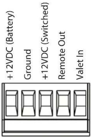
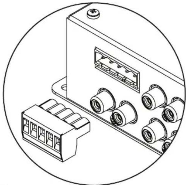
The TwK ^™ uses a removable plug for making power connections. Receptacles in the plug accept up to 16 AWG wire. To attach wires to the plug, use a small flathead screwdriver to back out the set screws. Strip 1/4 inch (6 mm) of insulation from the end of each wire and insert the bare wire into the receptacle, seating it firmly so that no wire is exposed. While holding each wire in place, tighten the set screw firmly, taking care not to strip the head of the screw.
! IMPORTANT
Use caution to ensure correct polarity and wire placement of power connections.
natural_image
Technical line drawing of an electrical connector housing with multiple ports and connectors (no text or symbols)! IMPORTANT
Make sure to observe proper orientation when inserting the Power Connector plug. The plug is keyed to fit in one direction only. When inserted correctly, the set screws should be facing down.
Use good quality crimp connectors (or solder with heat shrink tubing) when making connections to a vehicle's electrical system. Protect all wires from sharp edges (metal dash frame, firewall, etc.) by carefully routing and securing them, using grommets and loom where appropriate. Failure to do so may result in a dangerous short circuit.
Top View*
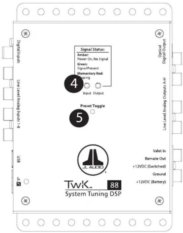
1 Power Connections Page 6
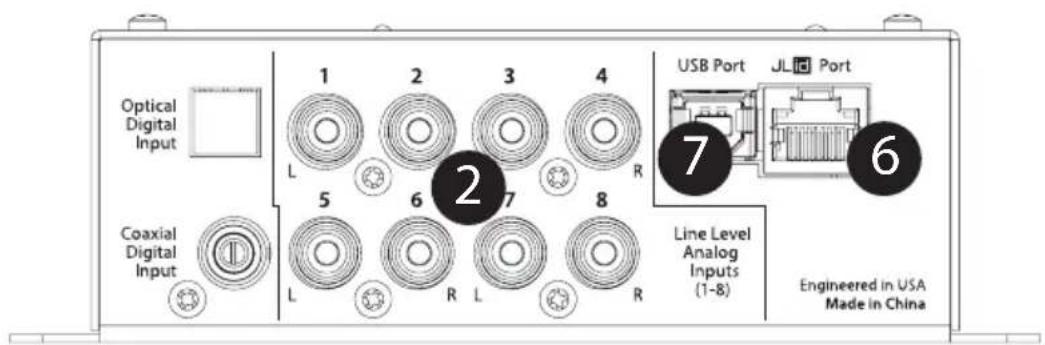
2 Input Connections* Page 7
3 Output Connections Page 7
4 Signal Status LEDs Page 8
5 Preset Toggle Button Page 8
6 JLid™ Port and DRC-200 Function Page 8
7 USB Port Page 9
*TwK™ 88 pictured. TwK™ D8 equipped with Optical Digital Input only.
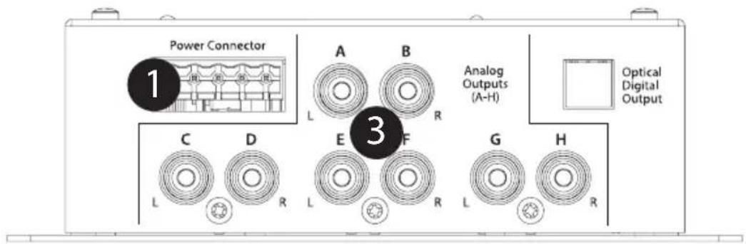
Power Connection / Audio Output Panel*
Input Panel*
1 Power Connections
The TwK ^™ has a 5-pin "Power Connector" jack located next to the "Analog Outputs". The Power Connector jack accepts the removable 5-pin plug and is used to make the connections below.
| Plug | Connection Description |
| Power Connector | +12VDC (Battery) Positive (+12V) Power Connection |
| Ground Negative (GND) Ground Connection | |
| +12VDC (Switched) Positive (+12V) Turn-On Input | |
| Remote Out Positive (+12V) Turn-On Output | |
| Valet In Negative (GND) Ground Input (used to activate Valet Mode) |
! IMPORTANT
Never make power connections with a "live" wire. Always disconnect the vehicle's negative battery post before making any connections or adjustments to 12V power connections! Failure to make safe, tight, high-integrity connections can result in fire and extensive damage.
- Disconnect the vehicle's NEGATIVE battery post connection and secure the disconnected cable to prevent accidental reconnection during installation. This is an essential safety precaution during installation!
- +12VDC (Battery): Connect to a constant positive (+12V) source. The internal circuitry of this connection is equipped with a self-resetting fuse designed to protect the unit internally. To protect the vehicle and its electrical system from damage, always install an appropriate fuse within 18 inches (45 cm) of the +12V connection point. If this is the only device using the connection point, we recommend using a 1A fuse.
- Ground: Connect to a clean, solid metal grounding point. Ideally, the +12VDC (Battery) and Ground connections should be run to the same distribution points that the amplifiers use for their power and ground connections. This will minimize the possibility of noise in the system.
- +12VDC (Switched): This connection is used to turn-on the TwK ^™ and should be connected to the positive (+12V) remote turn-on output of your source unit or FiX ^™ 82 OEM Integration DSP.
- Remote Out: This connection provides a positive (+12V) turn-on voltage (100 mA limit) to activate other aftermarket signal processors or amplifiers (similar to an aftermarket head unit's remote turn-on lead). If your equipment requires more than 100 mA total for activation, this connection can be used to trigger a relay to control the equipment in your system.
- Valet In: When connected to negative ground, this input activates the Valet Mode Preset and will remain active until the ground connection is removed. This allows you to activate a single preset using an alternate, user defined method, without using the DRC-200 Digital Remote Controller. When active, this preset will override any preset currently selected by the DRC-200. Refer to the TwK™-TüN™ Overview included with the downloaded TüN™ Software for detailed info about the Valet Mode Preset.

Input Connections
For maximum versatility, the TwK ^™ 88 is equipped with three methods for connecting input signals. Select the input type that is appropriate for the specific equipment of your audio system.
Line-Level Analog Inputs: Eight female RCA jacks accept low-voltage, line-level audio signals, with configurable input sensitivity settings (up to 7.1 V RMS) using the TüN™ Software Interface. Engineered to combat induced cable noise, the input architecture is set up in a differential-balanced configuration, making these inputs compatible with virtually any analog, line-level audio signal.
Optical Digital Input: Toslink jack accepts 2-channel digital audio signal from any optical (S/PDIF) digital output, with a sample rate up to 96 kHz.
Coaxial Digital Input: Female RCA jack accepts 2-channel digital audio signal from any coaxial (S/PDIF) digital output, with a sample rate up to 96 kHz.
Functionally identical to the TwK ^™ 88, the TwK ^™ D8 is equipped with an optical (Toslink) digital input only. This connection preserves a pristine signal path in the digital domain and is intended for systems equipped with an optical (Toslink) digital output, such as our FiX ^™ 82 OEM integration DSP.

Output Connections
Both TwK ^™ 88 and D8 models offer two output types to feed audio signals to your aftermarket system. Select the output type that is appropriate for the specific equipment of your audio system.
Analog Outputs: Eight RCA-type, 4-volt (RMS) line-level output jacks are located next to the "Power Connector". Each channel pair is arranged together by letter (A-B, C-D, E-F, G-H), with each channel labeled (Left and Right). Analog outputs are compatible with most types of aftermarket signal processors or amplifiers. The level of this output is proportionate to the TwK"s input signal and may also be controlled by the included DRC-200 Digital Remote Controller.
Optical Digital Output: Located next to the "Analog Outputs (A-H)", this jack provides a digital audio output that is not susceptible to RF interference or noise-generating electrical conditions. This is a pass-through digital audio output, with no signal processing applied, and intended for use with other signal processors or amplifiers that have an optical (Toslink) digital audio input (S/PDIF) jack. Using the TüN® Software Interface, you may select which analog inputs are assigned to this output. The level of this output is fixed and is not affected by the included DRC-200 Digital Remote Controller. However, when Analog Inputs are selected as the Optical Digital Output's source, the level of this output will match the analog input sensitivity settings.

Signal Status LEDs
Located on top of the unit are two LEDs used to report the signal status of the Twk ^™ 88 / D8. Separated by "Input" and "Output", these LEDs may be referenced during setup and normal use. Refer to the markings above the LEDs for specific behavior condition.

Preset Toggle Button
Using the TüN™ Software Interface, different tuning and/or function preferences may be created and saved as presets. Located in a recess on top of the TwK™ is the Preset Toggle button. Press the Preset Toggle button to select/advance to the next enabled preset option. With each press, the JLid™ status LED color will change to reflect its assigned color as a visual confirmation. Pressing this button operates the same as pressing the inner knob of the included DRC-200 Digital Remote Controller. Refer to the TwK™-TüN™ Overview included with the downloaded TüN™ Software for detailed info about Preset functionality.

JLid™ Port and DRC-200 Function
The JLid™ Port is designed for connection of the DRC-200 Digital Remote Controller. Equipped with two rotary level controls and push-button activation, the DRC-200 adds the remote activation of the optional functions listed below.
Inner Rotary Control: By default, the inner rotary level control operates as a Master Volume Control. The DRC-200 maintains linear frequency response at all volume levels and delivers the best signal-to-noise performance for your audio system. To use, leave the volume control of your source unit at the specific volume position that was used during amplifier level setting and/or during calibration of your FiX™ OEM Integration DSP, if equipped. From now on, use the DRC-200's inner rotary control to adjust your audio system volume, leaving the volume control at the level used for calibration/amplifier level setting. You may continue to use the source unit's tone, balance and fader controls, if desired. Using the TüN® Software Interface, you may select which channels are affected by the inner level control or reconfigure it to operate as a zone level controller.
Outer Rotary Control: The outer rotary control is a secondary, assignable level control that can be configured to operate as a subwoofer level control, fader control or zone level control. Using the TüN® Software Interface, a vast combination of control assignment and mixing combinations may be programmed for each function type.
Push-Button Preset Toggle: Pressing the inner control knob of the DRC-200 operates the same as pressing the Preset Toggle button located on top of the unit (see Preset Toggle Button above). Each press will select/advance to the next enabled preset option. As a visual confirmation, the DRC-200's multi-color LED will also change to reflect the preset's assigned color.
We recommend mounting the DRC-200 within easy reach of the driver, on the center console or dashboard of the vehicle. Select an appropriate location to mount the control knob assembly and status LED on the dashboard or console of the vehicle. You will need to access the rear of the mounting panel for installation.
Note: Before drilling or cutting, make sure there is adequate space behind the mounting surface to fit the DRC-200 controller box and status LED, including its wire assembly and harness.
Control Knob Installation:
- Drill a 3/8" (9.5 mm) hole in the center of the mounting area.
- Remove the knobs (inner, then outer) from the DRC-200 shaft. Do NOT remove the preinstalled nut and washer.
- From behind, insert the controller's shaft through the drilled hole and push forward.
- Place a supplied washer, then nut on the front of the shaft and tighten using an 11 mm wrench or deep-well socket. Take care not to over-tighten this nut, especially when mounting to a plastic panel.
- Turn each control fully counter-clockwise and place the knobs on the shaft (outer, then inner) with their markers pointing at 7:00. The knobs should sit close to the panel, but still permit the button to be pushed.
- Route the control cable from the JLid Port of your TwK 88 / D8 and connect to the harness jack of the DRC-200 controller.
Status LED Installation:
- Drill an 8 mm hole in the center of the mounting area.
- From behind, insert the status LED (without its mounting grommet) through the drilled hole.
- Snap the mounting grommet over the LED body and then insert it into the hole and press until flush with the surface.

USB Port
The USB Port is designed for connection of a PC to your TwK ^TM processor using the supplied USB A/B cable. Once connected, you'll be able to use the JL Audio TüN ^TM Software Interface to setup and configure the full functionality of your TwK ^TM DSP. Refer to the TwK ^TM -TüN ^TM Overview included with the downloaded TüN ^TM Software for minimum system requirements and detailed info for the installation and use of the TüN ^TM Software Interface.
Troubleshooting
| Problem Possible Cause Possible Solution | ||
| TwkTM doesn’t turn on | Faulty fuse | Remove fuse and check with continuity meter. Replace if necessary. |
| Poor connection integrity | Check “Ground” and both “+12VDC” connections for pinched wires; ensure tight connections. | |
| Insufficient “+12VDC (Switched)” input | Make sure there is a sufficient +12V supply at the “+12VDC (Switched)” connection; if not, a relay may be required. | |
| Amps or processors not turning on | Poor connection integrity | Check “Remote Out” connections for pinched wires; ensure tight connections. |
| Low or no volume | Source unit/master volume set too low | Increase source unit volume; increase DRC-200 master volume control, if connected. |
Specifications
| Digital Specifications | ||
| Processor Intersil® D2Audio DAE-6 | ||
| Bit Depth / Sample Rate 24 bit / 48 kHz | ||
| Electrical Specifications | ||
| Power Supply Type Regulated DC-DC SMPS | ||
| Operating Voltage 10 - 16V DC | ||
| Standby Mode Current Draw < 1.5 mA | ||
| Operating Current Draw 0.7 A at 13.8V | ||
| Recommended Fuse Value 1 A | ||
| Recommended Fuse Type Fast-Acting, ATO/ATC or similar | ||
| Input Section | ||
| Analog | Number of Channels Eight via chassis-mounted female RCA jacks | |
| Type Line-Level, Differential-Balanced | ||
| Full-Scale Sensitivity Settings | 250mV / 350mV / 500mV / 710mV / 1.0V (default) / 1.4V / 2.0V / 2.8V / 4.0V / 5.6V / 7.1V RMS | |
| Digital | Type 1 S/PDIF Optical via chassis-mounted TOSLink connector | |
| Type 2 S/PDIF Coaxial via chassis-mounted female RCA jack | ||
| Sample Rates 44.1kHz / 48kHz / 88.2kHz / 96kHz | ||
| Resolution 16 / 20 / 24-bit | ||
| "Signal Present" Detection threshold -40dBFS | ||
| Output Section | ||
| Analog | Number of Channels Eight via chassis-mounted female RCA jacks | |
| Type Unbalanced | ||
| Output Impedance 450 ohms | ||
| Maximum Output Level 4V RMS | ||
| Signal to Noise Ratio 98dB (A-Weighted, referred to 4V RMS) | ||
| THD + Noise 0.02% at rated output (20Hz - 20kHz) | ||
| Digital Pass-Through | Type S/PDIF Optical via chassis-mounted TOSLink connector | |
| Sample Rate 48kHz | ||
| Resolution 24-bit | ||
| Source Digital output channels selectable from any input | ||
| Remote Control | ||
| Type DRC-200 Digital Remote Controller | ||
| Assignable Functions Master Volume + Trim; Master Volume + Fader; Zone Control | ||
| Dimensions | ||
| L x W x H 5.19 in. x 4.29 in. x 1.85 in. (132 mm x 109 mm x 47 mm) | ||
Limited Warranty – Electronics (USA)
JL Audio warrants this product to be free of defects in materials and workmanship for a period of two (2) years from the original date of purchase. This warranty is not transferrable and applies only to the original purchaser from an authorized JL Audio dealer. Should service be necessary under this warranty for any reason due to manufacturing defect or malfunction, JL Audio will (at its discretion), repair or replace the defective product with new or remanufactured product at no charge. Damage caused by the following is not covered under warranty: accident, misuse, abuse, product modification or neglect, failure to follow installation instructions, unauthorized repair attempts, misrepresentations by the seller. This warranty does not cover incidental or consequential damages and does not cover the cost of removing or reinstalling the unit(s). Cosmetic damage due to accident or normal wear and tear is not covered under warranty.
Warranty is void if the product's serial number has been removed or defaced.
Any applicable implied warranties are limited in duration to the period of the express warranty as provided herein beginning with the date of the original purchase at retail, and no warranties, whether express or implied, shall apply to this product thereafter. Some states do not allow limitations on implied warranties, therefore these exclusions may not apply to you. This warranty gives you specific legal rights, and you may also have other rights, which vary from state to state.
If you need service on your JL AUDIO product:
All warranty returns should be sent to JL Audio's Electronics Service Facility freight-prepaid through an authorized JL Audio dealer and must be accompanied by proof of purchase (a copy of the original sales receipt). Direct returns from consumers or non-authorized dealers will be refused unless specifically authorized by JL Audio with a valid return authorization number. Warranty expiration on products returned without proof of purchase will be determined from the manufacturing date code. Coverage may be invalidated as this date is previous to purchase date. Non-defective items received will be returned freight-collect. Customer is responsible for shipping charges and insurance in sending the product to JL Audio. Freight damage on returns is not covered under warranty.
For Service Information in the U.S.A. please call JL Audio Customer Service:
(95 4) 443-110 0
9:00 AM – 5:30 PM (Eastern Time Zone)
JL Audio, Inc.
10369 North Commerce Pkwy.
Miramar, FL 33025
(Do not send product for repair to this address)
International Warranties:
Products purchased outside the United States of America are covered only by that country's distributor and not by JL Audio, Inc.

- TwK™ 88 & D8
- System Tuning DSPs
- Protect Your Hearing!
- Installation Applications
- Safety Considerations
- Manual Application
- What's Included
- Product Overview
- ! IMPORTANT
- Specialty Software Requirement
- The TwK ™ 88 is equipped with the following features:
- Flexible input design:
- Flexible setup features:
- 8 Powerful 10-band equalizers with flexible assignment capabilities:
- 8 Analog, line-level outputs jacks (RCA), each with a full-featured tuning set:
- Optical (Toslink) jack provides a pass-through digital audio (S/PDIF) output, with no signal processing applied.
- Provides a dedicated remote turn-on voltage output for activating aftermarket audio equipment.
- JLid™ Port allows connection of the included DRC-200 Digital Remote Controller, adding dual configurable level controls and LED Status Reporting capabilities from the driver's seat.
- USB port allows PC access to update firmware and connection of TüN ™ Software Interface.
- Planning Your Installation
- Installation Procedure/Making Connections
- Power Connections
- Input Connections
- Output Connections
- Signal Status LEDs
- Preset Toggle Button
- JLid™ Port and DRC-200 Function
- Control Knob Installation:
- Status LED Installation:
- USB Port
- Troubleshooting
- Specifications
- Limited Warranty – Electronics (USA)
- Warranty is void if the product's serial number has been removed or defaced.
- If you need service on your JL AUDIO product:
- For Service Information in the U.S.A. please call JL Audio Customer Service:
- International Warranties:
Brand : JL Audio
Model : TwK D8
Category : Hi-Fi System