
SlamPak SLPK-CAN-SPYDER1 - Hi-Fi System JL Audio - Free user manual and instructions
Find the device manual for free SlamPak SLPK-CAN-SPYDER1 JL Audio in PDF.


| Product Type | Powered Subwoofer System |
| Brand | JL Audio |
| Model | SlamPak SLPK-CAN-SPYDER1 |
| Category | Hi-Fi System / Car Audio |
| Amplifier Power (RMS) | 300 W @ 2 Ω |
| Impedance | 2 Ω |
| Frequency Response | 20 Hz – 200 Hz |
| Subwoofer Size | 12 inches (306 mm) |
| Enclosure Type | Sealed / Ported (vented) |
| Dimensions (W x H x D) | 20.5 x 14.5 x 17.5 in (520 x 368 x 445 mm) |
| Weight | 22 lbs (10 kg) |
| Input Voltage | 12 V DC (vehicle electrical system) |
| Fuse Rating | 40 A (mini-ANL) |
| Input Sensitivity | 200 mV – 4 V |
| Filter Controls | Low-pass variable (50–200 Hz), Bass boost (0–12 dB) |
| Key Features | CAN bus integration, remote level control, auto turn-on (DC offset / signal sensing) |
| Installation | Professional installation recommended; ensure proper ventilation |
| Cleaning | Wipe with a soft, dry cloth; do not use liquid cleaners |
| Safety | Disconnect power before wiring; secure enclosure in vehicle |
| Spare Parts / Reparability | Contact JL Audio for authorized service; spare fuses available |
| Warranty | 2 years (limited) |
Frequently Asked Questions - SlamPak SLPK-CAN-SPYDER1 JL Audio
User questions about SlamPak SLPK-CAN-SPYDER1 JL Audio
0 question about this device. Answer the ones you know or ask your own.
Ask a new question about this device
Download the instructions for your Hi-Fi System in PDF format for free! Find your manual SlamPak SLPK-CAN-SPYDER1 - JL Audio and take your electronic device back in hand. On this page are published all the documents necessary for the use of your device. SlamPak SLPK-CAN-SPYDER1 by JL Audio.
USER MANUAL SlamPak SLPK-CAN-SPYDER1 JL Audio
INSTALLATION GUIDE for the
SLPK-CAN-SPYDER1 SKU#94491&94490
natural_image
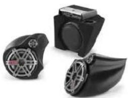
Three black plastic camera modules with visible internal components, shown from different angles (no text or symbols)Thank you for choosing a JL Audio Slampak ^® for your motorcycle sound system. With proper installation, your new vehicle specific enclosed sound system will deliver years of listening pleasure.
We strongly recommend that you have your new Slampak ^® installed by your authorized JL Audio dealer. The installation professionals employed by your dealer have the necessary tools and experience to disassemble and reassemble your vehicle properly. Also, keep in mind that your warranty coverage extends to 2 years if your system is installed or approved by your authorized JL Audio dealer. If you prefer to perform your own installation, please read this installation guide completely before beginning the process.
JL AUDIO.
Ahead of the Curve
SLPK-CAN-SPYDER1_INSIR_SKU#011312
! IMPORTANT
If you choose to perform the installation yourself, it is absolutely vital that the Stealthbox' be properly mounted to the vehicle according to these instructions. Failure to mount the enclosure properly presents two problems:
1) The sub-bass performance will suffer due to the movement of the enclosure caused by the force exerted by the woofer(s).
2) A loose enclosure presents a serious safety hazard in the event of a collision or sudden deceleration.
INSTALLATION DIFFICULTY:

ESTIMATED TIME: 5 HOURS
natural_image
Close-up of a black motorcycle with yellow safety guard patches, no visible text or symbolsSTEP 1
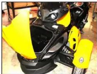
Empty out the front storage space of the motorcycle so that you have a clean area to work in.
If you are only installing the pods, skip to STEP 16.
natural_image
Close-up of a metallic mechanical component with red and yellow warning signs, no visible text or symbols.STEP 2
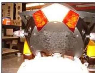
Remove the bottom panel above the rear tire as snow here
natural_image
Close-up of a black and yellow sports motorcycle with visible branding (no text or symbols on body)STEP 3
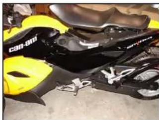
Lift the seat, remove the panel that simulates a gas tank at the top center of the motorcycle. Remove the two panels labelled "can am" (one on each side of the motorcycle) and the two panels labelled "spyder" (one on each side of the motorcycle).
Continued on Next Page
natural_image
Close-up of a car's front wheel and dashboard with yellow components (no visible text or symbols)STEP 4
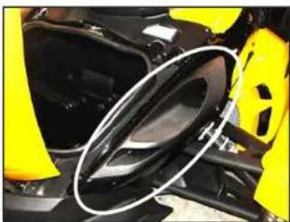
Remove the air duct body panels as indicated by the image at left. (One on each side of the motorcycle). There may be auxiliary lights installed in this panel, unplug them as the panel is removed.
If you are ONLY installing the pods and NOT the full system, but will be installing an amplifier in the front storage compartment, only remove the air duct body panel on the right hand side (where the harness enters the storage compartment (as seen in STEP 5 below), skip to STEP 6.
natural_image
Close-up of hands installing or adjusting a car engine component with yellow tape (no visible text or symbols)STEP 5
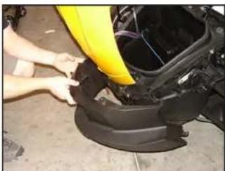
Remove the front Air dam.
natural_image
Close-up of a yellow car body panel with black plastic components and visible engine compartment (no text or symbols)STEP 6
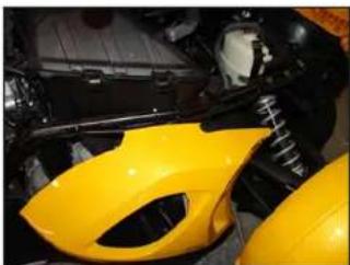
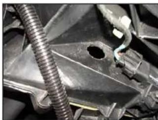
The harness for power, ground, remote turn on, signal and speakers will come down the right side of the motorcycle and enter the storage compartment in the upper right rear corner as shown below.
natural_image
Interior view of a car showing a battery pack and cable inside a vehicle (no visible text or symbols)STEP 7
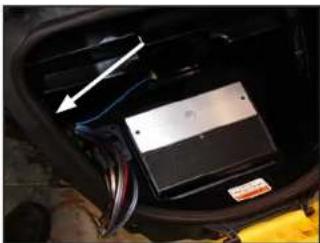
Looking down from the top front of the storage compartment, notice where the wire loom enters the compartment.
natural_image
Close-up of a mechanical component with a coiled spring and mounting holes (no visible text or symbols)STEP 8
Looking up from the front right tire, use a 1-1/8" hole-saw to cut a hole for the harness to come through as seen in STEP 7.
Before drilling, always make sure that you are not going to be drilling into any gas lines, brake lines, tires, transmission lines, electrical wiring, exhaust systems or anything else that might cause a reduction in your weekly pay.
Always wear eye protection when drilling!
natural_image
Interior view of a car dashboard with visible seats and a white arrow pointing to a component (no text or symbols)STEP 9
If you are ONLY installing the pods and NOT the full system, skip to STEP 16.
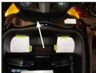
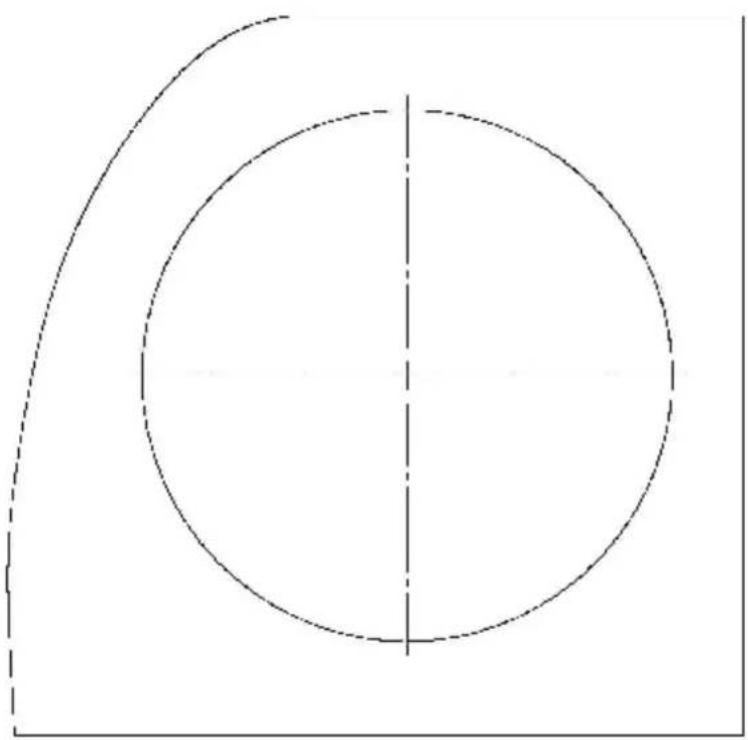
The two templates shown can be found on the last two pages of the install manual, cut them out and position them as shown.
Remove the panel directly above the storage compartment as indicated by the arrow.
natural_image
Close-up of a hand using a tool to adjust or install a component, no visible text or symbolsSTEP 10
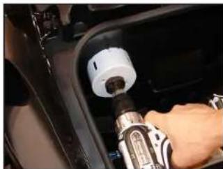
Mark the center positions of each template and cut the two holes, the holes should be 3-5/8" in diameter after they are cut.
USE ALL PRECAUTIONS WHEN CUTTING/DRILLING!
natural_image
Top-down view of a black car front bumper with visible seats and dashboard (no text or symbols)STEP II
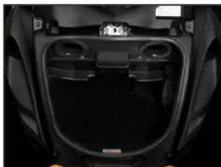
Mount the beveled hole trims as shown using the 8 supplied #6-1 x 3/4" Philips head screws (4 per trim).
natural_image
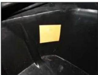
Close-up of a black surface with a yellow sticky note (no text or symbols visible)STEP 12
Looking down and towards the front right corner of the storage compartment, position the wax square as shown.
natural_image
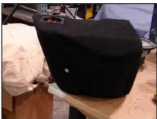
Black cap on a wooden surface with tools and a small inset showing red buttons (no visible text or symbols)STEP 13
Thread the 3/8-16 x 1-1/4" Hex Head Bolt all the way into the enclosure. Press the enclosure down into the storage compartment towards the right front corner, the Hex Head Bolt will leave an indentation in the wax square.
Once you've confirmed the indentation in the wax square, remove the Hex Head Bolt from the enclosure.
natural_image
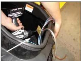
Close-up of hands holding a car tire with a hose and cable, no visible text or symbolsSTEP 14
Drill a 5/16" hole where the indentation was made in STEP 13.
Before drilling, always make sure that you are not going to be drilling into any gas lines, brake lines, tires, transmission lines, electrical wiring, exhaust systems or anything else that might cause a reduction in your weekly pay.
Always wear eye protection when drilling!
natural_image
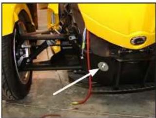
Close-up of a yellow car wheel with attached red cable and a white arrow pointing to a small component (no visible text or symbols)STEP 15
Install the 3/8-16 x 1-1/4" Hex Head Bolt through the included Split Lock Washer, the 1-1/4" Fender Washer and the hole drilled in STEP 14 into the enclosure, tighten this fastener down.
Once this fastener is light, the front air dam can be re-installed.
natural_image
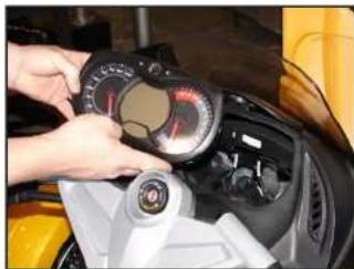
Close-up of hands adjusting a motor dashboard with a yellow vehicle (no visible text or symbols)STEP 16
Remove gauge cluster as shown by lifting top panel then depressing two locking tabs on top of the cluster.
natural_image
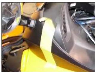
Close-up of a car interior with yellow safety tape and mechanical components (no visible text or symbols)STEP 17
Put a length of masking tape as shown on each side of the top fairing.
natural_image
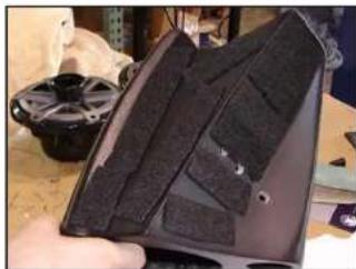
Close-up of a hand holding a black hard-shell device with visible straps, placed on a workbench (no text or symbols visible)STEP 18
Remove the larger speaker from each pod, the smaller speaker can remain in the pod. The speakers are only secured in the pods for shipping with 3-screws, use all six when re-installing: (in the following pictures, both speakers have been removed, this is NOT necessary)
Position foam strips as shown on each pod.
Note the location of the three holes in the pods, two will be used to mount the pod, the third will be the wire run.
natural_image
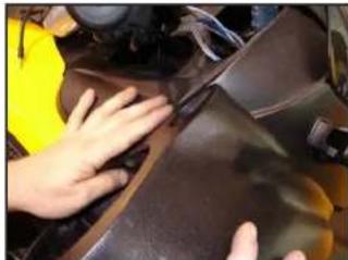
Close-up of hands cleaning a car body with a yellow safety patch (no visible text or symbols)STEP 19
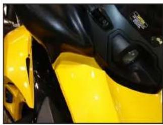
Align pod with the back edge matching the fairing (as shown) and the front corners as show in STEP 20.
natural_image
Close-up of a yellow motorcycle's front wheel and side panel (no visible text or symbols)STEP 20
alignment of the front of each pod, once both front and rear alignment is achieved, use a marker to make marks on the masking tape shown in STEP 17 through the holes in the pods identified in STEP 18.

natural_image
Close-up of a hand using a power tool to clean the yellow and black car body (no visible text or symbols)STEP 21
Drill the holes as marked through the fairing, each hole needs to be 5/16" in diameter.
Before drilling, always make sure that you are not going to be drilling into any gas lines, brake lines, tires, transmission lines, electrical wiring, exhaust systems or anything else that might cause a reduction in your weekly pay.
Always wear eye protection when drilling!
natural_image
Close-up of a mechanical component with a white arrow pointing to a specific part (no visible text or symbols)STEP 22
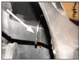
Looking through the gauge cluster location, install the "U-Bolt" around the steel dash structure and through the two upper holes drilled in STEP 21.
natural_image
Close-up of a yellow and black sports equipment component (no visible text or symbols)STEP 23
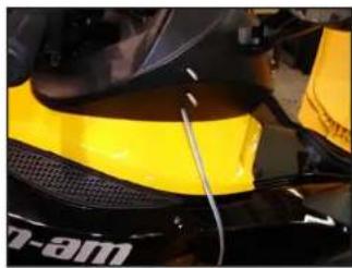
Run the speaker wire through the bottom hole drilled in STEP 21 as shown.
natural_image
Close-up of a kitchen utensil with a yellow tool and a bowl containing red liquid, placed on a wooden surface (no text or symbols visible)STEP 24
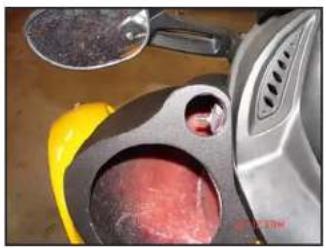
Set each pod into position, with the "U-Bolt" coming through the two upper holes and the wire coming through the bottom hole. Secure the pod to the motorcycle using the included 1/4 x 1" Fender Washer and 1/4" Nyloc Nut on each leg of the "U-Bolt", tighten using a rotation method similar to changing a tire so that both legs are tightened simultaneously.
I look up the wire to the speaker and, re-install speakers into pods.
If you are ONLY installing the pods and NOT the full system, You have completed your installation of the pods.
Run the wire from either side of the fairing to your source (or amplifier) location.
Enjoy your new Slampak!
natural_image
Close-up of a car engine bay with hoses and connectors (no visible text or symbols)STEP 25
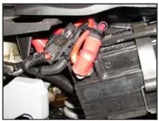
Locate the battery above the rear line, disconnect the negative battery terminal. Secure the fuse holder close to the terminal, remove the fuse. Attach the ring terminal for the positive battery run to the positive battery terminal and run the cable from the battery terminal to the fuse holder. Attach the cable to the fuse holder. Attach the remaining cable to the output of the fuse holder and run it through the included Split Room.
Make sure on all cabling runs to secure all wires when running them so that they cannot get tangled in any moving parts or the exhaust system.
natural_image
Close-up of a mechanical component with a metallic bracket and mounting holes (no visible text or symbols)STEP 26
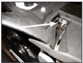
Under the seat, directly above the fuse panel, you'll notice a grounding point, this is an excellent location to get a good ground for the amplifier, secure the ring terminal for the ground to this point. Run the ground cable so that it can integrate into the Split Room with the positive battery cable. Again,
Make sure on all cabling runs to secure all wires when running them so that they cannot get tangled in any moving parts or the exhaust system.
natural_image
Close-up of a car's engine compartment with visible wiring and components (no text or symbols)STEP 27
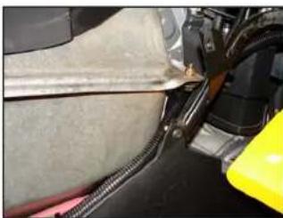
Run the power cables up the right hand side of the motorcycle, securing it as described earlier at regular intervals alongside the frame or other cable runs.
natural_image
Close-up of a car's brake system with spring and yellow component (no visible text or symbols)STEP 28
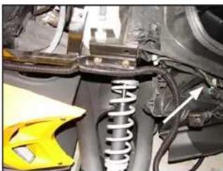
Make sure that the cabling is secured so that there is no way that it can get tangible in any moving parts on the motorcycle, including steering, suspension, exhaust or passengers. The cable will be joined by the speaker wire, signal wire for the B.C and signal from the source, just before it enters the front storage compartment (through the hole drilled in STEP 8, as shown by arrow.)
natural_image
Close-up of a yellow motorcycle's front wheel and dashboard with visible wiring and a white arrow pointing to the engine component (no text or symbols)STEP 29
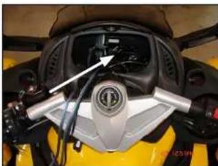
From the gauge cluster location, there should be the two speaker wires, the wire for the Remote Level Control (it looks like a phone cord), the small gauge blue remote turn on wire (included) and the signal cable.
natural_image
Close-up of mechanical components with a white arrow pointing to a damaged component (no visible text or symbols)Many people find it easier to run the mini plug on the signal cable up from the amplifier location than running the cars on the amplifier end of that cable down. If you choose to run that cable up, run a "pull line" or, string along with it, that way, once the run is made, you can use the pull line to pull the other cables down towards the amplifier.
STEP 30
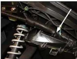
Again, secure all cables along the full run to ensure that they cannot get tangled in any moving parts or the exhaust system.
The signal and speaker wires will join with the power cables that came up the side of the motorcycle and all enter the front storage compartment through the hole drilled in STEP 8, as shown by arrow.
Page 5 • JL Audio, Inc 2010
natural_image
Close-up of a black mechanical component with a metallic connector and cable (no visible text or symbols)STEP 31
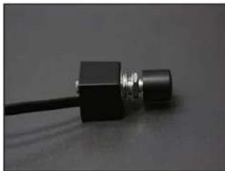
To mount the Remote level control, determine a convenient and safe location, drill a 3/8" hole.
natural_image
Close-up of a black industrial component with a metallic grille and wiring, no visible text or symbolsBefore drilling, always make sure that you are not going to be drilling into any gas lines, brake lines, tires, transmission lines, electrical wiring, exhaust systems or anything else.
Always wear eye protection when drilling!
Gently but firmly, pull the knob off of the control, use the supplied washers and nut to "sandwich" the surface you just drilled the hole in, mount the control, replace the knob.

natural_image
Front view of a black and yellow 3D-printed sports car (no visible text or symbols)STEP 32
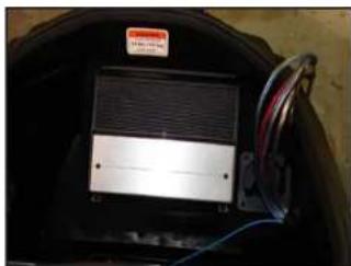
Follow the included instructions for installing the XD400/4 the small blue wire that was run down from the Gauge cluster area needs to be spliced in to a accessory switched power source so that, the amplifier turns off when the motorcycle is turned off. If the amplifier remains on when the motorcycle is turned off, there is strong potential for battery drainage! All connections should be made at this time.
After all connections are made, review the schematic on page 6, make sure that all wires are where they belong.

natural_image
Front view of a yellow and black three-wheeled vehicle (no visible text or symbols)STEP 33
Double check all connections, once everything has been confirmed as good, install the fuse near the battery.
Re-install all removed bodywork, don't miss any of the hardware.

natural_image
Front view of a yellow and black motorcycle with front wheel, shown from rear angles against a dark background (no text or symbols visible)STEP 34
CONGRATULATIONS!
You have completed the installation for this model!
Enjoy your new Slampak ^®
Please refer to the Power Recommendation section for suggestions on basic amplifier set-up help. For further details on the amplifier, please reference the amplifier owners manual (included).
Continued on Next Page
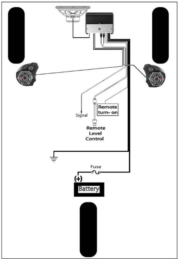
flowchart
graph TD
    A["Battery"] -->|+| B["Fuse"]
    B --> C["Remote Level Control"]
    C --> D["Signal"]
    D --> E["Remote turn-on"]
    E --> F["Top Sensor"]
    style A fill:#000,stroke:#fff,color:#fff
    style B fill:#000,stroke:#fff,color:#fff
    style C fill:#000,stroke:#fff,color:#fff
    style D fill:#000,stroke:#fff,color:#fff
    style E fill:#000,stroke:#fff,color:#fff
    style F fill:#000,stroke:#fff,color:#fff
Page 6· JL Audio, Inc 2010
SLPK-CAN-SPYDER1_INSTIR_SKU#011312
INCLUDED HARDWARE
20) 4 9/16" Nylon Cable tie 1) 10" 1/2" Flex Loom
8) #6-12 x 3/4" Screw 1) HD-RLC (Remote Level Control)
2) Port Beze 1) XD-MFB-MAXI
1) XC-MINIRCA-6 2) 1/4-20 U Bolt (for Spyder)
4) Nylon Locknuts 1) 3/8-16 x 1-1/4" Hex Head Bolt
1) 3/8" Split Lock Washer 1) 3/8" x 1-1/4" Fender Washer
1) 3" x 3" Wax Square 4) 1/4 x 1" Fender Washer
SPECIFICATIONS
(Subwoofer)
Enclosure Type: Acoustic Suspension (sealed)
Driver Type:
Nominal Impedance: 4 Ohms
Continuous Power Handling: 150 Watts
POWER RECOMMENDATION

Above is pictured the settings as we tested the Slampak ^® here, you may find that your settings offer slightly.
All JL Audio amplifiers are very versatile audio components. Please consult the owner's manual for even more detailed information about installing and tuning your amplifier.
CONNECTIONS
A schematic of your Slampak® system is seen at the left, please use it as reference when testing or troubleshooting.
Using quality power, signal and speaker wire is essential in ensuring the performance of your Slampak®.
JL Audio Has chosen and tested the wire included in your Slampak® through very rigorous standards, it will provide the best performance for your system.
JL AUDIO® Ahead of the Curve™
(954) 443-1100 www.jlaudio.com
All specifications are subject to change without notice "Linole" and the "Laudetigo" "Sextinans" and the "Streethra" (quareogestest) instruments of Linole in "Barclalthe" may not require basic instrumenting.
L.A. 18,000 2017, 2018 - Pritadin USA - ©2018.3 Audio, Inc. - U.S. RIBNEx #5/19/194 A#24888 #5,116,694 #5,229,502 #4,245,749 #5,240,973 #5,216,644 #5,096,700 #5,401,335 #5,387,707 #5,319,531 N#27,352 #427,001 #5,480,753 Other U.S. & Foreign personnel. For more detailed information: www.deutis.com.
18369 NORTH COMMERCE PARKWAY - MIARAM, FLORIDA - 33025 - USA
natural_image
Simple geometric diagram showing a circle with a vertical dashed diameter and a curved line above it (no text or symbols)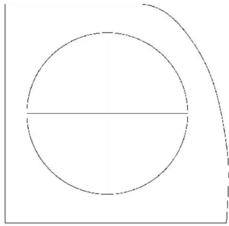
natural_image
Simple geometric diagram showing a circle with a horizontal line and a curved dashed line, no text or symbols present.
Brand : JL Audio
Model : SlamPak SLPK-CAN-SPYDER1
Category : Hi-Fi System