
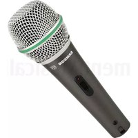
Stage 212 - Microphone SAMSON - Free user manual and instructions
Find the device manual for free Stage 212 SAMSON in PDF.


| Product Type | Dual-Channel Wireless Microphone System |
| Brand | Samson |
| Model | Stage 212 |
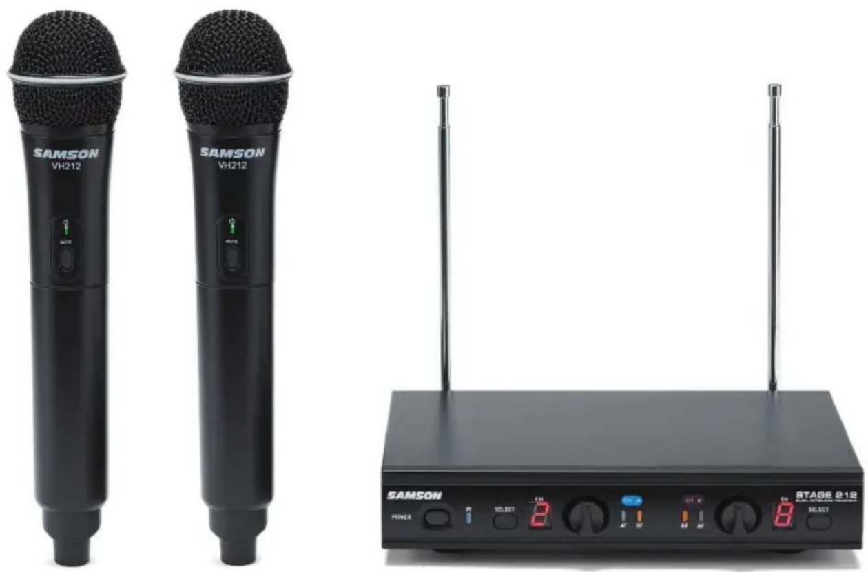
| System Components | SR212 Receiver, 2 VH212 Handheld Transmitters |
| Operating Frequency | VHF 173–198 MHz |
| Number of Channels | 12 (selectable) |
| Modulation | FM |
| Operating Range | Up to 50m (200 ft) line-of-sight |
| Frequency Response | 80 Hz – 15 kHz |
| Receiver Dimensions (W x D x H) | 210 x 145 x 36 mm |
| Receiver Weight | 0.6 kg |
| Transmitter Dimensions (Dia x L) | 55 x 255 mm |
| Transmitter Weight | 0.22 kg (each) |
| Receiver Power Supply | 100-240 V AC, 50/60 Hz; adapter output DC 15V, 800 mA |
| Transmitter Power Source | 2 x AA batteries (up to 10 hours) |
| Receiver Outputs | 2 unbalanced 1/4" jacks, 1 balanced XLR mixed output |
| Transmitter RF Power | 10 mW |
| Microphone Element | Dynamic (Q6 capsule) |
| Care and Cleaning | Clean only with a dry cloth |
| Spare Parts and Repairability | No user-serviceable parts inside; refer servicing to qualified personnel. Batteries are user-replaceable. |
| Safety | Read all instructions; do not expose to water or moisture; do not open the device. |
Frequently Asked Questions - Stage 212 SAMSON
User questions about Stage 212 SAMSON
0 question about this device. Answer the ones you know or ask your own.
Ask a new question about this device
Download the instructions for your Microphone in PDF format for free! Find your manual Stage 212 - SAMSON and take your electronic device back in hand. On this page are published all the documents necessary for the use of your device. Stage 212 by SAMSON.
USER MANUAL Stage 212 SAMSON
Frequency-Agile, Dual-Channel Wireless System
OWNER'S MANUAL
Copyright 2017, Samson Technologies Corp. v1.1
Samson Technologies Corp.
278-B Duffy Ave
Hicksville, NY 11801
www.samsontech.com
Important Safety Information

ATTENTION RISQUE DE CHOC ÉLECTRONIQUE - NE PAS OUVRIR

This lightning flash with arrowhead symbol within an equilateral triangle is intended to alert the user to the presence of non-insulated “dangerous voltage” within the product’s enclosure that may be of sufficient magnitude to constitute a risk of electric shock.

The exclamation point within an equilateral triangle is intended to alert the user to the presence of important operating and maintenance instructions in the literature accompanying the appliance.
WARNING: TO REDUCE THE RISK OF ELECTRIC SHOCK, DO NOT REMOVE COVER (OR BACK) AS THERE ARE NO USER-SERVICEABLE PARTS INSIDE. REFER SERVICING TO QUALIFIED SERVICE PERSONNEL.

If you want to dispose this product, do not mix it with general household waste. There is a separate collection system for used electronic products in accordance with legislation that requires proper treatment, recovery and recycling.
Private household in the 28 member states of the EU, in Switzerland and Norway may return their used electronic products free of charge to designated collection facilities or to a retailer (if you purchase a similar new one).
For Countries not mentioned above, please contact your local authorities for a correct method of disposal.
By doing so you will ensure that your disposed product undergoes the necessary treatment, recovery and recycling and thus prevent potential negative effects on the environment and human health.
Important Safety Information
FCC Rules and Regulations
Samson wireless receivers are certified under FCC Rules part 15 and transmitters are certified under FCC Rules part 74.
Licensing of Samson equipment is the user's responsibility and licensability depends on the user's classification, application and frequency selected.
NOTE: This equipment has been tested and found to comply with the limits for a Class B digital device, pursuant to part 15 of the FCC Rules. These limits are designed to provide reasonable protection against harmful interference in a residential installation. This equipment generates, uses and can radiate radio frequency energy and, if not installed and used in accordance with the instructions, may cause harmful interference to radio communications. However, there is no guarantee that interference will not occur in a particular installation. If this equipment does cause harmful interference to radio or television reception, which can be determined by turning the equipment off and on, the user is encouraged to try to correct the interference by one or more of the following measures:
- Reorient or relocate the receiving antenna.
- Increase the separation between the equipment and receiver.
- Connect the equipment into an outlet on a circuit different from that to which the receiver is connected.
- Consult the dealer or an experienced Radio/TV technician for help.
The device has been evaluated to meet general RF exposure requirement.
To maintain compliance with FCC's RF exposure guidelines, this equipment should be installed and operated with a minimum distance of 20cm between the radiator and your body.
The manufacturer is not responsible for any radio or TV interference caused by unauthorized modifications or change to this equipment. Such modifications or change could void the user's authority to operate the equipment.
This radio transmitter (identify the device by certification number or model number if Category II) has been approved by Industry Canada to operate with the antenna types listed below with the maximum permissible gain indicated. Antenna types not included in this list, having a gain greater than the maximum gain indicated for that type, are strictly prohibited for use with this device.
This device complies with Part 15 of the FCC rules and Industry Canada license-exempt RSS standard(s).
Operation is subject to the following two conditions:
(1) this device may not cause harmful interference, and
(2) this device must accept any interference received, including interference that may cause undesired operation.
WARNING: Changes or modifications not expressly approved by the party responsible for compliance could void the user's authority to operate the equipment.
Important Safety Information
- Read these instructions.
- Keep these instructions.
- Heed all warnings.
- Follow all instructions.
- Do not use this apparatus near water.
-
Clean only with dry cloth.
-
Do not block any ventilation openings. Install in accordance with the manufacturer's instructions.
-
Do not install near any heat sources such as radiators, heat registers, stoves, or other apparatus (including amplifiers) that produce heat.
-
Do not defeat the safety purpose of the polarized or grounding type plug. A polarized plug has two blades with one wider than the other. A grounding type plug has two blades and a third grounding prong. The wide blade or the third prong are provided for your safety. If the provided plug does not fit into your outlet, consult an electrician for replacement of the obsolete outlet.
-
Protect the power cord from being walked on or pinched particularly at the plugs, convenience receptacles, and at the point where they exit from the apparatus.
-
Only use attachments/accessories specified by the manufacturer.
-
Use only with the cart, stand, tripod, bracket, or table specified by the manufacturer, or sold with the apparatus. When a cart is used, use caution when moving the cart/apparatus combination to avoid injury from tip-over.
-
Unplug the apparatus during lightening storms, or when unused for long periods of time.
-
Refer all servicing to qualified personnel. Service is required when the apparatus has been damaged in any way, such as power supply cord or plug is damaged, liquid has been spilled or objects have fallen into the apparatus has been exposed to rain or moisture, does not operate normally, or has been dropped.
-
This appliance shall not be exposed to dripping or splashing water and that no object filled with liquid such as vases shall be placed on the apparatus.
-
Caution-to prevent electrical shock, match wide blade plug wide slot fully insert.
-
Please keep a good ventilation environment around the entire unit.
-
The direct plug-in adapter is used as disconnect device, the disconnect device shall remain readily operable.
-
Batteries (battery pack or batteries installed) shall not be exposed to excessive heat such as sunshine, fire or the like.
-
The AC plug considered as disconnect device of adapter.

Introduction
Congratulations on purchasing the Samson Stage 212 Dual Microphone Wireless System! The Stage 212 system is the perfect solution for any application requiring two high quality, wireless microphones in an easy to use package. Featuring simple operation, with 12 available channels and infrared set for the transmitter channel, the Stage 212 can quickly be up and running out of the box. The system includes the SR212 dual channel receiver with individual and mixed outputs. Also included are two VH212 handheld microphone transmitters.
With the Stage 212 system, you'll have great sound quality with clear reception, and the ability to walk freely around your venue. For any live sound application (karaoke, presentation, education, house of worship, etc.) the Stage 212 is the ideal tool for your dual-performer needs. The Stage 212 provides outstanding performance and reliability.
Although this product is designed for intuitive operation, we suggest you take some time to go through these pages to learn how we've implemented a number of unique features, and to get step-by-step instructions for setting up your system. If your Stage 212 was purchased in the United States, you'll also find a warranty card enclosed—please don't forget to follow the instructions so that you can receive online technical support, and so that we can send you updated information about this and other Samson products. Also, be sure to check out our website
(www.samsontech.com) for complete information about our full product line.
We recommend that you record your serial number in the space provided below, for future reference.
Serial number:
Date of purchase: ____
Should your unit ever require servicing, a Return Authorization (RA) number must be obtained before shipping your unit to Samson. Without this number, the unit will not be accepted. Please call Samson at 1-800-3SAMSON (1-800-372-6766) for an RA number prior to shipping your unit. Please retain the original packing materials and, if possible, return the unit in the original carton. If you purchased your Samson product outside the United States, please contact your local distributor for warranty information and service.
Features
• Professional, dual-handheld wireless system for use in both live sound and sound contracting applications
- 12 available channels operating in the VHF band designed for maximum system compatibility in the same location without interference
- Individual 14 " and mixed XLR outputs
- Up to 200' of line-of-sight operating range
- Two professional VH212 handheld transmitters with Q6 Dynamic Microphone capsules
- Up to 10 hours of battery life, using two standard AA batteries
SR212 Receiver Front Panel Features
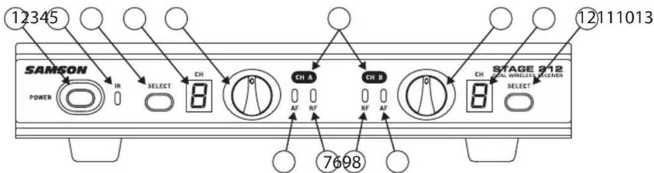
- Power Switch - Press to turn the receiver on or off.
- IR Transmitter - During "IR SET" an infrared light is used to set the transmitter channel.
- Channel A SELECT Button - Press this button to cycle through Channel A receiver's operating channels. Press and hold this button to send the channel information to the transmitter via infrared transmission.
- LED Display - The 7-segment LED display shows each receiver's current operating channel. The channels are indicated by 1–9 and A–C.
- VOLUME Control (CH A) - This knob sets the level of the audio signal being output through the CH A output jacks on the rear panel. Reference level is obtained when the knob is turned fully clockwise (to its "10" setting).
- Channel A AF Indicator - Lights green when the corresponding Channel A VH212 transmitter is powered on, and there is an audio signal present and detected by the receiver. The indicator lights red when the transmitted audio signal is overloaded.
- Channel A RF Indicator - Lights orange when the corresponding Channel A VH212 transmitter is powered on, and there is an RF signal present and detected by the receiver.
- Channel B AF Indicator - Lights green when the corresponding Channel B VH212 transmitter is powered on, and there is an audio signal present and detected by the receiver. The indicator lights red when the transmitted audio signal is overloaded.
- Channel B RF Indicator - Lights orange when the corresponding Channel B VH212 transmitter is powered on, and there is an RF signal present and detected by the receiver.
- Volume Control (Channel B) - This knob sets the level of the audio signal being output through the CH A output jacks on the rear panel. Reference level is obtained when the knob is turned fully clockwise (to its "10" setting).
- LED Display - The 7-segment LED display shows each receiver's current operating channel. The channels are indicated by 1–9 and A–C.
- Channel B SELECT Button - Press this button to cycle through Channel B receiver's operating channels. Press and hold this button to send the channel information to the transmitter via infrared transmission.
- Channel Label - The channel label designates the frequency group. The label color matches the label color of the corresponding handheld microphone transmitter.
SR212 Receiver Rear Panel Features
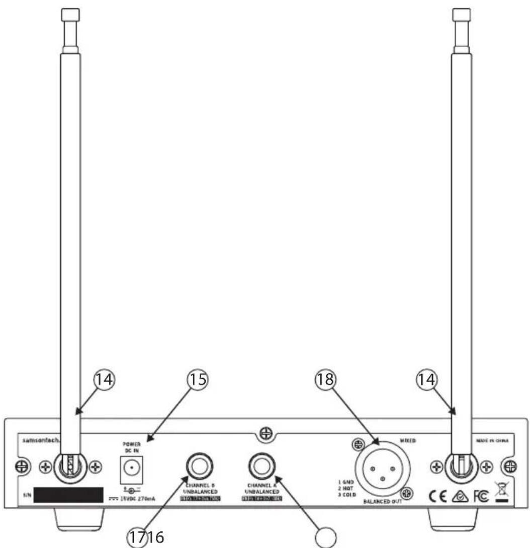
- Antenna - The antenna mountings allow full rotation for optimum placement. In normal operation, both antennas should be placed in a vertical position. The antennas can be folded down for convenience when transporting the SR212.
- DC Input - Connect the supplied 15-volt adapter here. WARNING: Do not substitute any other kind of power adapter. Doing so can cause damage to the SR212 and will void your warranty.
- Channel A Output - Use this unbalanced, 14 " jack to connect the SR212 Channel A receiver to the line level input of a mixer, amplifier, or other audio equipment.
- Channel B Output - Use this unbalanced, 14 " jack to connect the SR212 Channel B receiver to the line level input of a mixer, amplifier, or other audio equipment.
- MIXED OUT - This balanced, low impedance XLR jack carries a mix of both the Channel A and Channel B receivers.
VH212 Transmitter Controls and Features
- Status Indicator - This LED displays the operation mode:
| GREEN Normal Operation | |
| RED Mute | |
| Flashing GREEN Low Battery | |
- Power/Mute Switch - Press and hold to turn the unit on or off. Press and release to mute or unmute the transmitter.
- Battery Cover - Unscrew the battery cover and slide down to open the VH212 battery compartment.
- Battery Holder - Open the battery holder by pressing the tab and lifting the cover. Insert two standard AA (LR6) batteries here, being sure to observe the plus and minus polarity markings shown.
WARNING: Do not insert the batteries backwards; doing so can cause severe damage to the VH212 and will void your warranty.
- Input GAIN Control - This control adjusts the transmitter input sensitivity. For optimal performance, using the included screwdriver, set the input GAIN control to where you see the VH212 PEAK indicator start to light under high levels, then turn down until the PEAK light stops lighting.
- IR Lens - This window is used to capture the infrared signal sent from the VH212 during the IR SET to channelize the transmitter. The battery cover must be open and the IR Lens facing towards the receiver to load the selected channel.
- Plastic Screwdriver - Designed for use in adjusting the VH212 input GAIN control (See #5 Input GAIN Control).


Quick Start
In order for your wireless system to work correctly, both the receiver and transmitter must be set to the same channel.
Follow this basic procedure for setting up and using your Stage 212 wireless system:
Physically place the SR212 receiver where it will be used, and fully extend the antennas vertically. The general rule of thumb is to maintain “line of sight” between the receiver and transmitter so that the person using or wearing the transmitter can see the receiver.
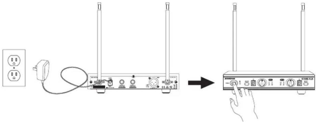
With the SR212 powered off, connect the included power adapter. Turn the SR212 on momentarily to confirm that the unit is receiving power. You'll see the LED display light up. Then turn the SR212 power off.
With your amplifier or mixer off and volume control all the way down, connect the SR212 receiver 1/4" outputs (or XLR Mix Output) to the inputs of a mixer or amplifier. Turn the Level knob on the SR212 completely counterclockwise, then turn its power on.
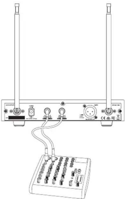
natural_image
Line drawing of a network device with two towers, two connected ports, and a terminal block (no text or symbols)Quick Start
With the transmitter powered off, install two fresh AA batteries into VH212 handheld transmitter. Leave the battery compartment open.
Turn on the power to the transmitter by pressing and holding Power switch; the indicator LED will light green.

Press the CH A SELECT button on the front of the SR212 to choose an available channel for the CH A receiver. The channel number will increase by one digit, from 1–9 then A–C. Once the last channel has been reached, the count will cycle back to 1.

Quick Start
Position the VH212 transmitter about 6-12" (15-30 cm) from the front of the SR212 receiver with the transmitter's IR window facing the IR transmitter on the front panel of the SR212 receiver.
Press and hold the SR212 CH A SELECT button to set the transmitter to the same channel as the receiver via infrared transmission

When the transmission is complete, the SR212 will receive RF signal and the tone key from the transmitter. The CH A READY indicator will light on the front panel of the SR212 receiver. Repeat these steps for the CH B transmitter and receiver. CH A and CH B available frequency channels do not overlap, so you can set the two receivers to the same channel number or letter.
Turn on your connected amplifier or mixer, but keep the volume all the way down. Set the Volume knob on the SR212 fully clockwise (to its "10" setting). This is unity gain.
Speak or sing into the microphone. Slowly raise the volume of your amplifier or mixer until the desired level is reached.
If you find the system has noticeable dropouts, reduced overall working range, or unexpected noise bursts, change the operating channel of the system using the steps above.
When using multiple systems in the same frequency band, each system must be set to a different operating channel.
Specifications
System Specifications
Operating Frequency VHF 173MHz to 198MHz
Number of Channels 12 channels
Frequency Stability ±0.005%
Modulation Mode FM
Maximum Deviation ±30 kHz
Operating Range 50 meter
Operating Temperature Range 40° to 43°
Working Humidity 65±20%RH
Frequency Response 80 Hz to 15kHz
Tone Key Frequency 30.00kHz
SR212 Receiver Specifications:
Image Rejection 35 dB
Dynamic Range 100 dB
Maximum Output 1.37V
Sensitivity -100dBm@30dB SINAD
Output Connectors Two 6.3mm unbalanced, One XLR balanced
Audio Output Levels -12dB
Power Supply 100-240V, 50/60Hz, 0.4A, Output: DC 15V, 800mA
Dimensions 210 x 145 x 36 (mm)
Net Weight 0.6kg
VH212 Transmitter Specifications
RF Power Output 10mW
Microphone Element Dynamic
Typical Battery Life 10 hours
Current Consumption 120 mA typical
Dimensions 055 mm x 255 mm
Net Weight 0.22kg
At Samson, we are continually improving our products, therefore specifications and images are subject to change without notice.
Troubleshooting
| Issue Solutions | |
| No Audio | Turn on the VH212 transmitter using the Power/Mutr switch. |
| Ensure the VH212 transmitter's batteries are installed correctly. | |
| Confirm that the SR212 adaptor is correctly connected and plugged into an electrical outlet. | |
| Turn on the SR212 receiver. | |
| Make sure the SR212 output and audio input connections are securely connected. | |
| Ensure that the SR212 receiver and VH212 transmitters are in line of sight with one another. | |
| Check the receiver and audio input device level controls. | |
| Distorted Audio | Check the receiver output level and audio input device level. |
| Check the VH212's batteries and replace if low. | |
| Another transmitter may be broadcasting on the same channel. Turn off transmitter that may be causing interference. | |
| Audio Dropout | The transmitter may be too far away from the receiver. Move closer to the receiver, or reposition the antennas. |
| Remove any sources that may cause RF interference, such as cell phones, cordless phones, lighting equipment, computers, etc. | |
| Transmitters and Receiver on Different Channels | Contact your Samson reseller or distributor for assistance. |
Samson Technologies
278-B Duffy Ave
Hicksville, NY 11801
Phone: 1-800-3-SAMSON
www.samsontech.com
- Important Safety Information
- FCC Rules and Regulations
- This device complies with Part 15 of the FCC rules and Industry Canada license-exempt RSS standard(s).
- Introduction
- Features
- SR212 Receiver Front Panel Features
- SR212 Receiver Rear Panel Features
- VH212 Transmitter Controls and Features
- Quick Start
- Specifications
- System Specifications
- SR212 Receiver Specifications:
- VH212 Transmitter Specifications
- Troubleshooting
Brand : SAMSON
Model : Stage 212
Category : Microphone