
FHPH132AB1 - Air conditioner FRIGIDAIRE - Free user manual and instructions
Find the device manual for free FHPH132AB1 FRIGIDAIRE in PDF.


| Product Type | Portable Air Conditioner |
| Model | FHPH132AB1 |
| Brand | Frigidaire |
| Cooling Capacity | 13,200 BTU |
| Heating Function | Yes (for heat & cool models) |
| Power Supply | 115V AC, 60Hz |
| Modes | Cool, Dry, Fan, Heat, Auto |
| Fan Speeds | High, Medium, Low, Auto |
| Timer | 24-hour programmable |
| Sleep Mode | Yes |
| Swing Function | Yes (louver swing) |
| Remote Control | Included with batteries |
| Filter | Washable, two filters (A and B) |
| Drainage Methods | Continuous drainage (garden hose), heat pump drainage (1/4" hose) |
| Safety Features | GFCI plug with Test/Reset, current detection device |
| Warranty | 1 year limited warranty |
| Installation | Window kit for double-hung or sliding sash windows |
| Fault Codes | AS (room sensor), E4 (communication), ES (pipe sensor), P1 (full tank) |
Frequently Asked Questions - FHPH132AB1 FRIGIDAIRE
User questions about FHPH132AB1 FRIGIDAIRE
0 question about this device. Answer the ones you know or ask your own.
Ask a new question about this device
Download the instructions for your Air conditioner in PDF format for free! Find your manual FHPH132AB1 - FRIGIDAIRE and take your electronic device back in hand. On this page are published all the documents necessary for the use of your device. FHPH132AB1 by FRIGIDAIRE.
USER MANUAL FHPH132AB1 FRIGIDAIRE
natural_image
Line drawing of a rectangular appliance with lid and side buttons (no text or symbols)TABLE OF CONTENTS
Important Safety Instructions....2-3
Product Registration....4
Normal Sounds....4
Unit Description....5
Accessories Included....5
Installation Instructions....6-7
Air Conditioner Features....8
Operating Instruction....8-17
Care and Cleaning....18
Before You Call....19
Major Appliance Limited Warranty....20
Important Safety Instructions

NOTE:
This USE & CARE MANUAL provides specific operating instructions for your model. Use the Portable air conditioner only as instructed in this USE & CARE MANUAL. These instructions are not meant to cover every possible condition and situation that may occur. Common sense and caution must be practiced when installing, operating, and maintaining any appliance.

NOTE:
The power supply cord with this air conditioner contains a current detection device designed to reduce the risk of fire.
Please refer to the section 'Operation of Current Device' for details. In the event that the power supply cord is damaged, it cannot be repaired. It must be replaced with a cord from the product manufacturer.

WARNING
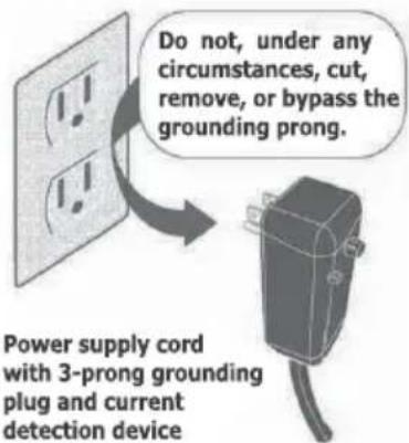
Avoid fire hazard or electric shock. Do not use an extension cord or an adaptor plug. Do not remove any prong from the power cord.
Grounding type wall receptacle

WARNING
For Your Safety
Do not store or use gasoline or other flammable vapors and liquids in the vicinity of this or any other appliance. Read product labels for flammability and other warnings.

WARNING
Prevent Accidents
To reduce the risk of fire, electrical shock, or injury to persons when using your air conditioner, follow basic precautions, including the following:
- Be sure the electrical service is adequate for the model you have chosen. This information can be found on the serial plate, which is located on the side of the cabinet.
- If the air conditioner is to be installed in a window, you will probably want to clean both sides of the glass first.
- Be sure the air conditioner has been securely and correctly installed according to the installation instructions in this manual. Save this manual for possible future use in removing or reinstalling this unit.

WARNING
Electrical Information
The complete electrical rating of your new portable air conditioner is stated on the serial plate. Refer to the rating when checking the electrical requirements.
- Be sure the air conditioner is properly grounded. To minimize shock and fire hazards, proper grounding is important. The power cord is equipped with a three-prong grounding plug for protection against shock hazards.
- Your air conditioner must be used in a properly grounded wall receptacle. If the wall receptacle you intend to use is not adequately grounded or protected by a time delay fuse or circuit breaker, have a qualified electrician install the proper receptacle.
- Do not run air conditioner without outside protective cover in place. This could result in mechanical damage within the air conditioner.
- Do not use an extension cord or an adapter plug.

SAFETY PRECAUTIONS
DANGER! Avoid Serious Injury or Death
• This air conditioner contains no user-serviceable parts. Always call an authorized Electrolux servicer for repairs.
- Do not insert or place fingers or objects into the air discharge area on top of the unit.
• Do not start or stop the air conditioner by unplugging the power cord or turning off the power at the electrical box.
- Do not cut or damage the power cord.
- If the power cord is damaged, it should only be replaced by an authorized Electrolux servicer.
- In the event of a malfunction (sparks, burning smell, etc.), immediately stop the operation, disconnect the power cord, and call an authorized Electrolux servicer.
• Do not operate the air conditioner with wet hands.
• Do not pull on the power cord.
- Do not drink any water that is drained from the air conditioner.

SAFETY PRECAUTIONS
CAUTION! Avoid Injury or damage to the unit or other property
• Provide ventilation per installation instructions.
• Do not direct airflow at fireplaces or other heat related sources as this could cause flare ups or make units run excessively.
- Do not climb on or place objects on the unit.
• Do not hang objects off the unit.
- Do not place containers with liquids on the unit.
• Turn off the air conditioner at the power source when it will not be used for an extended period of time.
- Periodically check the condition of the unit's installation accessories for any damage.
- Do not apply heavy pressure to the radiator fins of the unit.
• Operate the unit with air filter in place.
- Do not block or cover the intake grille, discharge area and outlet ports.
- Ensure that any electrical/electronic equipment is one yard away from the unit.
- Do not use or store flammable gases near the unit.
READ THIS SECTION BEFORE ATTEMPTING TO OPERATE AIR CONDITIONER. Unit must be upright for one hour prior to operating.
Operation of Current Device
Plug in & press RESET
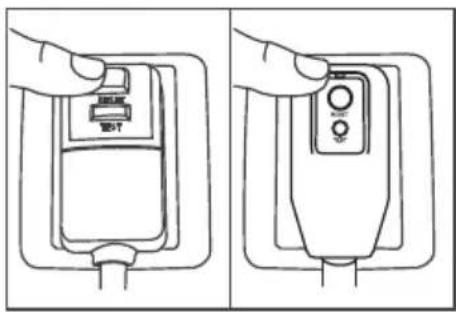
The power supply cord contains a current device that senses damage to the power cord. To test your power supply cord do the following:
- Plug in the Air Conditioner.
- The power supply cord will have TWO buttons on the plug head. Press the TEST button. You will notice a click as the RESET button pops out.
- Press the RESET button. Again you will notice a click as the button engages.
- The power supply cord is now supplying electricity to the unit.(On some model, this is also indicated by a light on the plug head)

NOTE:
- Do not use this device to turn the unit on or off.
• Always make sure the RESET button is pushed in for correct operation. - The power supply cord must be replaced if it fails to reset when either the TEST button is pushed, or it cannot be reset. A new one can be obtained from the product manufacturer.
• If power supply cord is damaged, it CANNOT be repaired. It MUST be replaced by one obtained from the product manufacturer.

CAUTION
- This appliance is not intended for use by persons (including children) with reduced physical, sensory or mental capabilities or lack of experience and knowledge, unless they have been given supervision or instruction concerning use of the appliance by a person responsible for their safety.
• Children should be supervised to ensure that they do not play with the appliance. - If the supply cord is damaged, it must be replaced by the manufacturer, its service agent or similarly qualified persons in order to avoid a hazard.
- The appliance shall be installed in accordance with national wiring regulations.
• The appliance shall not be installed in the laundry rooms.
Product Registration & Normal Sounds
Product Registration
Record Your Model and Serial Numbers
Record in the space provided below the mode and serial numbers. On all models, the serial plate is located on the side of the cabinet.
Model No.
Serial No.
Register Your Product
The self-addressed PRODUCT REGISTRATION CARD should be filled in completely, signed and returned to the Frigidaire Company.
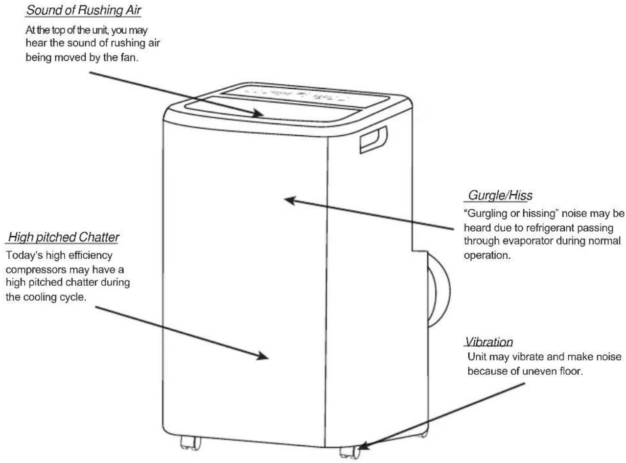
Normal Sounds
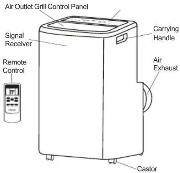
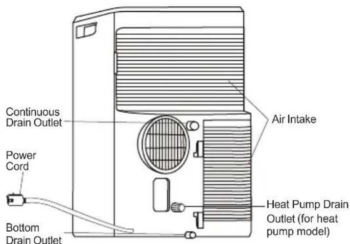
Unit Description
Accessories Included
| PARTS: PARTS NAME: | QUANTITY: | |
 | Window Kit Connector A1 pc | |
 | Exhaust hose connector B1 pc | |
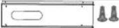 | Window Kit1 set | |
 | Exhaust Hose1 pc | |
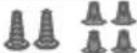 | Screws4 pcs (/2" screws)+2 pcs (3/4" screws) | |
 | Safety Lock1 pc | |
 | Bolts2 pcs | |
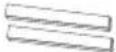 | Foam seal A2 pcs | |
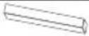 | Foam seal B1 pc | |
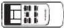 | Remote Control1 pc | |
| [ZKC0] | Battery2 pcs | |
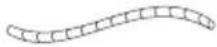 | Drain hose1 pc | |
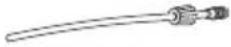 | Drain hose and connector(for heat pump model)1 set (78.7"(2m)) | |
Installation Instructions
EXHAUSTING HOT AIR
In the Cool Mode the appliance must be placed close to a window or opening so that the warm exhaust air can be ducted outside.
First position unit on a flat floor and is within the vicinity of a single circuit outlet power source. Make sure there's a minimum of 31.5" clearance in the front/back of the unit, and a minimum of 19.7" clearance in the left/right sides of the unit.
- Extend both side of the exhaust hose(Fig.1)
- Install the connector B into the unit (Fig.2).
- Affix the connector A into the window slider kit and seal.(Fig.3&4)
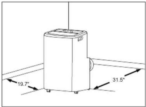
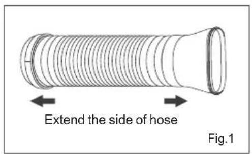
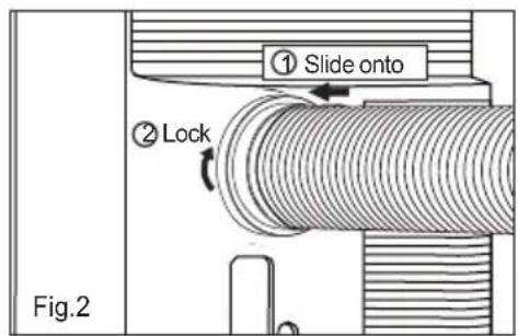
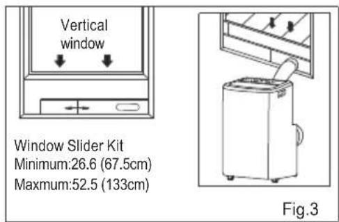
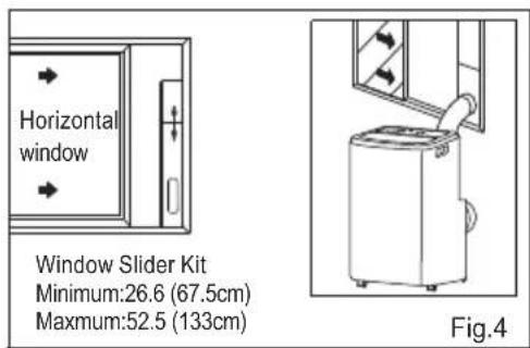
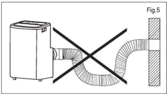
The hose can be extended from its original length of 15"up to 59", but it is the best to keep the length to minimum required. Also make sure that the hose does not have any sharp bends or sags.(Fig.5)
natural_image
Diagram showing a washing machine connected to a curved pipe with diagonal lines, labeled Fig.5 (no text or symbols on the diagram itself)Installation Instructions(continued)
Installation in a double-hung sash window
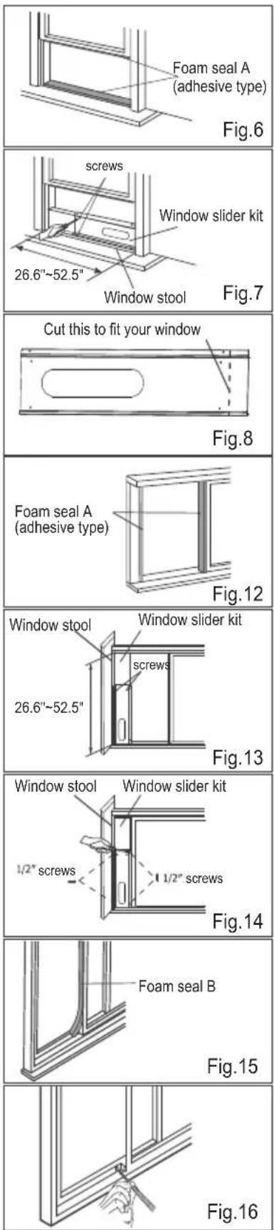
- Cut the foam seals A(adhesive type) to the proper lengths and attach them to the window and stool.(Fig.6)
- Open the window sash and place the window slider kit on the window stool (Fig.7). Attach the window slider kit to the window stool. Adjust the length of the window slider kit according to the width of window. Screw down the two screws on the window slider kit. See Fig.7.
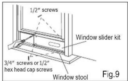
Cut the adjustable window slider kit if the width of window is less than 26.6 inches(Fig.8). - Close the window sash securely against the window slider kit.(Fig.9)
- Drive two 1/2 screws to secure the window slider kit to the window sash.(Fig.9)
- Secure the window slider kit to the window stool (Fig.9):
A: For wooden window: Use 3/4 screws for securing.
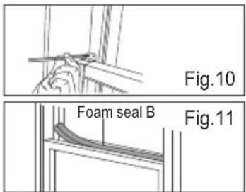
B: For Vinyl-Clad windows: Use 1/2 hex head cap screws for securing. - To secure lower sash in place, attach right angle sash lock with 1/2 (12.7mm) screw as shown(Fig.10).
NOTE: It is difficult to lock the windows with the sash lock for Vinyl-Clad windows, so you can use lock by window itself. - Cut the foam seal B to an appropriate length and seal the open gap between the top window sash and outer window sash, as shown in
Fig.11.
Installation in a sliding sash window
- Cut the foam seals A(adhesive type) to the proper lengths and attach them to the window frame. See Fig.12.
- Open the window sash and place the window slider kit on the window stool (Fig.13). Attach the window slider kit to the window stool. Adjust the length of the window slider kit according to the height of window. Screw down the two screws on the window slider kit. See Fig.13.
Cut the adjustable window slider kit if the height of window is less than 26.6 inches(Fig.8). - Close the window sash securely against the window slider kit. (Fig.14)
- Drive two 1/2 screws to secure the window slider kit to the window sash.(Fig.14)
- Drive two 3/4 screws to secure the window slider kit to the window stool. (Fig.14)
- Cut the foam seal B to an appropriate length and seal the open gap between the sliding sash and outer window sash, as shown in Fig.15.
- To secure sliding sash in place, attach right angle sash lock with 1/2 (12.7mm) screw as shown (Fig.16).
Air Conditioner Features & Operating Instructions
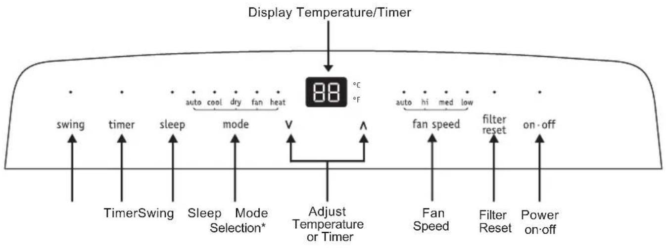
Control Panel
flowchart
graph TD
    A["Display Temperature/Timer"] --> B["88 °C"]
    B --> C["auto cool dry fan heat"]
    B --> D["auto hi med low"]
    B --> E["fan speed"]
    B --> F["fan Speed"]
    B --> G["Filter Reset"]
    B --> H["Power on-off"]
    I["swing"] --> J["TimerSwing"]
    K["timer"] --> L["sleep"]
    M["mode"] --> N["Sleep Mode Selection*"]
    O["V"] --> P["Adjust Temperature or Timer"]
    Q["↑"] --> R["Fan Speed"]
    S["↑"] --> T["Filter Reset"]
    U["↑"] --> V["Power on-off"]
*Note: "heat" mode is for heat & cool models only.
Operating Instruction
Cool mode
Press the "mode" button until the Cool mode indicator lights.
Press the "fan speed" button to choose the fan speed according to the illumination of the fan speed indicator.
You can choose the "hi", "med", "low", or "auto" fan speed setting.
Press the "∧" or "∨" button to choose the temperature you want.

Dry mode
Press the "mode" button until the Dry mode indicator lights. In this mode, the "A" or "V" button is disabled and the screen displays the room temperature. The unit will continuously drain moisture from the room.
Note: In this mode, the fan speed will be set as "low" automatically, which cannot be changed.
In this mode, condensate drainage are required, refer to the "Drainage Instructions" on Page 16-17 for more instructions to drain the excess condensate.

Fan mode
Press the "mode" button until the Fan mode indicator lights.
In this mode, you can select fan speed "hi", "med" or "low".
The screen displays room temperature.
Note: In this mode, the air exhaust hose does not need to be connected.

Heat mode(For Heat & Cool models only)
Press the "mode" button until the Heat mode indicator lights.
Press the “Λ” or “V” button to choose the temperature you want.
Press the "fan speed" button to choose the fan speed according to the illumination of the fan speed indicator.
You can choose the "hi", "med", "low", or "auto" fan speed setting.
Note: The unit have a build in condensate pump to pump out the excess condensate during heating mode.
Condensate drainage are required, refer to the "Drainage Instructions" on Page 16-17 for more instructions to drain the excess condensate.

AUTO mode
Press the "mode" button until the AUTO mode indicator lights.
Press the “A” or “V” button to choose the temperature you want. The screen will display the setting temperature. In this mode, the unit will automatically select cooling, heating (not applicable for cooling only models), or fan only operation depending on what temperature you have selected and the room temperature. The air conditioner will control room temperature automatically round the temperature point set by you.
Note: In this mode, fan speed cannot be selected.

Timer mode
The timer facilitates the user to delay the unit startup or shutdown.
How to delay startup
Plug in the unit, so the unit turns to standby.
Press the "timer" button, then the Timer indicator and number of hours on the screen will light.
Tap or hold the UP arrow (A) or the DOWN arrow (V) to change delay start timer at 0.5 hour increments up to 10 hours, then at 1 hour increments up to 24 hours.
After 5 seconds, the setting will be confirmed automatically and the control will count down the time remaining until startup.
The unit will start up in the mode as previously set. Press the "timer" button again within 5 seconds, you will quit the timer setting directly.
To cancel the setting, press the "timer" button again will show the remain time and press the button again to quit the function.

How to delay shutdown
You can delay shutdown when the unit is on.
Press the "timer" button, then the Timer indicator and number of hours on the screen will light.
Tap or hold the UP arrow (A) or the DOWN arrow (V) to change delay shutdown timer at 0.5 hour increments up to 10 hours, then at 1 hour increments up to 24 hours.
After 5 seconds, the setting will be confirmed automatically and the control will count down the time remaining until shutdown. Press the "timer" button again within 5 seconds, you will quit the timer setting directly.
To cancel the setting, press the "timer" button again will show the remain time and press the button again to quit the function.

Sleep mode
When the unit is in Cool, Heat or Auto mode, you can press the "sleep" button to make the unit run in Sleep mode. In this mode, the fan speed will be set as "auto" automatically, which cannot be changed.
In Cool/Heat mode the selected temperature will increase/decrease by 2 °F 30 minutes after the mode is selected.
The temperature will then increase/decrease by another 2 °F after an additional 30 minutes. This new temperature will be maintained for 7 hours before it returns to the originally selected temperature. This ends the "Sleep" mode and the unit will continue to operate as originally programmed.
The "Sleep" mode program can be cancelled at any time during operation by pressing the "Sleep", "mode", "fan speed" or "on-off" button.
Note: In Fan or Dry mode, Sleep mode cannot be set.
During Sleep mode the brightness of the indicators will reduce by half.

Louver Swing Function
Press the "swing" button to enable louver swing function, the swing indicator will illuminate and the louver on the top panel will swing up and down. Press this button again to disable the louver swing function.

Filter reset
This feature is a reminder to clean the Air Filter (See Care and Cleaning) for more efficient operation.
The filter indicator will illuminate after 250 hours of fan operation. Press the "filter reset" button, to reset after cleaning the filter.

°F /°C function
Press the “ ” and “ V ” button the same time for more than 3 seconds to switch between degree Fahrenheit and degrees Celsius.
Note: Under Dry/Fan mode, you can not select °F/°C.
Remote Control
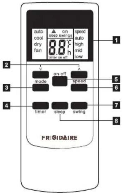
Cool Only models
1 Remote Control screen
2 Temp/Timer setting button
3 Mode button
4 Timer button
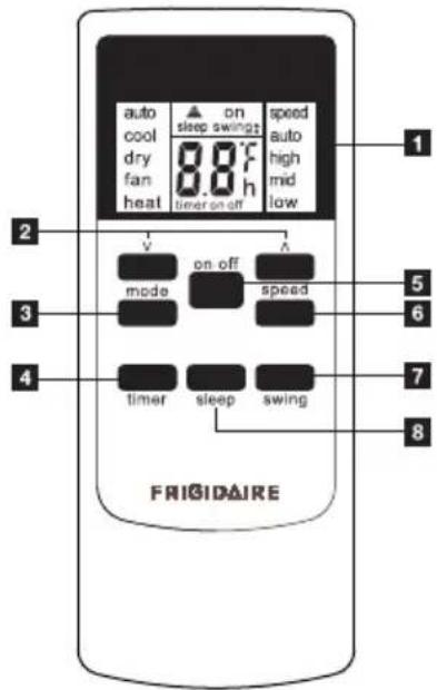
Heat and Cool models
5 on-off button
6 Fan Speed button
7 Swing button
8 Sleep button
Battery Installation and Important Instructions
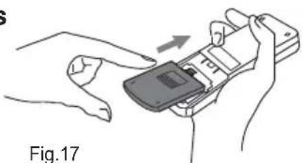
Remove the cover at the back of the remote control. Insert the provided batteries correctly(see the instructions inside the battery compartment).
Close up the cover.
To replace the old batteries(which have been used up) with two new R03 "AAA" 1.5V batteries, repeat the steps above.
natural_image
Illustration of hands holding a mobile phone with an arrow indicating rotation (no text or symbols)If the remote control unit is replaced or discarded, the batteries must be removed and disposed of in accordance with local legislation as they do harm to the environment.
Do not mix old and new batteries.
Do not mix alkaline, standard (carbon-zinc) or rechargeable (nickel-cadmium) batteries.
Do not dispose of batteries in fire. Batteries may explode or leak. If the remote control is not used for a long time, remove the batteries from the remote control.
The remote control must be handled with extreme care. Do not drop it or expose it to direct sunlight or sources of heat.
This device complies with Part 15 of the FCC Rules. Operation is subject to the following two conditions:
(1) This device may not cause harmful interference, and (2) this device must accept any interference received, including interference that may cause undesired operation.
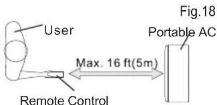
Point the remote control at the location of the signal receiver. The remote control must be no more than 16 ft(5 meters) away from the unit (without obstacles between the remote control and the unit).
All rights reserved.
How to Use the Remote Control
TURNING THE UNIT ON
Plug in the unit, then press the "on-off" button (when turned on, the unit will operate as the last setting before shutdown.
To switch the unit off, press "on-off" button again, then remove the plug.
Do NOT switch the unit off by removing the plug.
Always switch the unit off by pressing the "on-off" button and wait for few minutes before removing the plug.
Cool mode
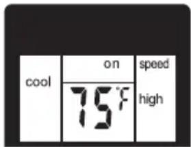
Press the "mode" button until the left side of LCD screen displays "cool".
Press the “fan speed” button to choose the fan speed “auto”, “high”, “mid”, and “low”.
Press the “A” and “V” button to choose the temperature you want.
Dry mode
Press the "mode" button until the left side of LCD screen displays "dry".
In this mode, the “Λ” or “V” button is disabled and the screen will remain blank. The unit will continuously drain moisture from the room.
Note:
In this mode, the fan speed will be set as "low" automatically, which cannot be changed.
In this mode, condensate drainage are required, refer to the
"Drainage Instructions" on Page 16-17 for more instructions to drain the excess condensate.

Fan mode
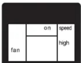
Press the "mode" button until the left side of LCD screen displays "fan".
In this mode, you can select fan speed "high", "mid", "low" by pressing the Fan speed button and referring to the diagram.
Note: In this mode, the air exhaust hose does not need to be connected.
Operating Instructions
Heat mode(For Heat & Cool models only)
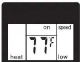
Press the "mode" button until the left side of LCD screen displays "heat".
Press the “A” and “V” button to choose the temperature you want.
Press the "fan speed" button to choose the fan speed "auto", "high", "mid", and "low".
Note: In this mode, condensate drainage are required, refer to the "Drainage Instructions" on Page 16-17 for more instructions to drain the excess condensate.
Auto mode
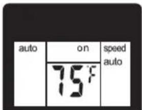
Press the "mode" button until the left side of LCD screen displays "auto".
Press the “Λ” and “V” button to choose the temperature you want.
In this mode, the unit will automatically select cooling, heating(not applicable for cooling only models), or fan only operation depending on what temperature you have selected and the room temperature. The air conditioner will control room temperature automatically round the temperature point set by you.
Note: In this mode, fan speed cannot be selected.
Sleep mode
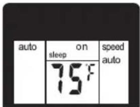
When the unit is in Cool, Heat or Auto mode, you can press the "sleep" button to make the unit run in Sleep mode. In this mode, the fan speed will be set as "auto" automatically, which cannot be changed.
In Cool/Heat mode the selected temperature will increase/decrease by 2 °F 30 minutes after the mode is selected. The temperature will then increase/decrease by another 2 °F after an additional 30 minutes. This new temperature will be maintained for 7 hours before it returns to the originally selected temperature. This ends the "Sleep" mode and the unit will continue to operate as originally programmed.
The "Sleep" mode program can be cancelled at any time during operation by pressing the "Sleep", "mode", "fan speed" or "on-off" button.
Note: In Fan or Dry mode, Sleep mode cannot be set.
Louver Swing Function
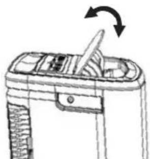
Press the "swing" button to enable louver swing function, and the upper side of screen will display "swing‡". The louver on the top panel will swing up and down.
Press this button again to disable the louver swing function.
natural_image
Line drawing of a mechanical device with an arrow indicating rotation (no text or symbols)Fig.19
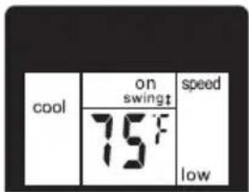
°F /°C function
Press the “ ” and “ ” button the same time for more than 3 seconds to switch between degree Fahrenheit and degrees Celsius.
Note: Under Dry/Fan mode, you can not select °F/°C.
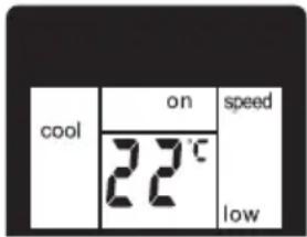
Timer mode
How to delay startup
Plug in the unit, so the unit turns to standby.
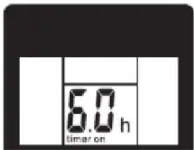
Press the "timer" button, when the unit is off. The screen will display "timer" and "h", and the "on" will flashing. Tap or hold the UP arrow "A" or the DOWN arrow "V" to change delay start timer at 0.5 hour increments up to 10 hours, then at 1 hour increments up to 24 hours. After 3 seconds, the timer function is enabled, then "on" will stop flashing, the display will show the temperature back and the control will count down the time remaining until startup. The unit will start up in the mode as previously set.
To cancel the setting, press the "timer" button again. You can also cancel the setting by pressing the "on-off" button.
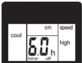
How to delay shutdown
You can delay shutdown when the unit is on.
Press the "timer" button, when the unit is on. The screen will display "timer" and "h", and the "off" will flashing. Tap or hold the UP arrow "A" or the DOWN arrow "V" to change delay shutdown timer at 0.5 hour increments up to 10 hours, then at 1 hour increments up to 24 hours. After 3 seconds, the timer function is enabled, then "off" will stop flashing, the display will show the temperature back and the control will count down the time remaining until shutdown.
To cancel the setting, press the "timer" button again. You can also cancel the setting by pressing the "on-off" button.
Fault Code
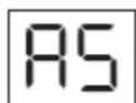
If the screen on the unit displays "AS", the room temperature sensor has failed. Contact your Authorize Frigidaire Service Center.
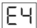
If the display reads "E4", the communication between display PCB and main control PCB is faulty. Contact your Authorized Frigidaire Service Center.
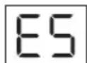
If the screen on the unit displays "ES", the pipe temperature sensor has failed. Contact your Authorize Frigidaire Service Center.
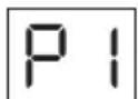
If the screen on the unit displays "P1", the water collection tank inside the unit should be full. Refer to the "Drainage Instructions" on Page 16-17 for more instructions to drain the successive condensate. If error repeats, contact your Authorize Frigidaire Service Center.
Drainage Instructions
Continuous Drainage
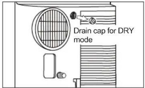
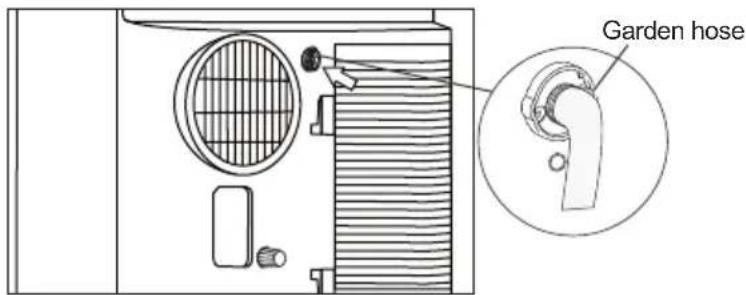
During the Dry mode, you will need a garden hose (sold separately) to drain the condensate from the unit. Follow the steps below:
• Unscrew the drain cap of continuous drain outlet(Fig.20).
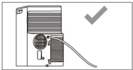
- Connect one end of the garden hose (sold separately) to the drain outlet then lead the other end into a drain that is lower than the unit(Fig.21).
Figure 20 Figure 21
NOTE
- Condensate may flow out after removing the drain cap, if the unit is running in Cool or Auto mode. When you want to remove the garden hose, prepare a drip tray (not supplied) to collect the condensate from the drain outlet.
- Please be sure that the height of the drain and section of the drain hose should not be higher than that of the drain outlet, or the continuous drainage may not work properly.
- During Cool or Auto mode, it is recommended to disable continuous drainage by replacing the drain cap to the drain outlet, to reach the maximum performance.
natural_image
Diagram of a portable air conditioner unit with a coiled cable and ventilation duct, no text or symbols present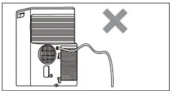
natural_image
Diagram of a portable air conditioner unit with a warning symbol (no text or labels present)Heat pump Drainage(For heating & cooling model only)
During the Heat mode, you will need a 1/4" drainage hose (packed with the unit) to drain the condensate from the unit.
Follow the steps below:
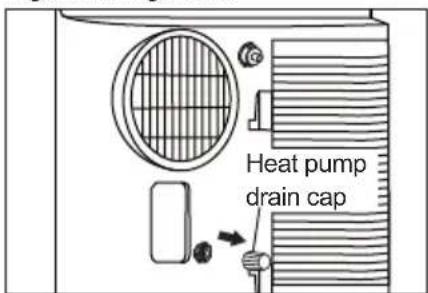
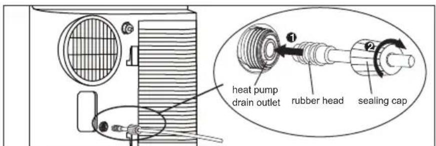
• Unscrew the heat pump drain cap and rubber of heat pump drain outlet(Fig.22).
- Insert the rubber head into the outlet. Then screw the sealing cap into the heat pump drain outlet(Fig.23).
- Lead the other end of the 1/4" drainage hose to a drain that is not 16ft(5m) higher than the heat pump drain outlet.
Figure 22 Figure 23
Drainage Instructions
NOTE:
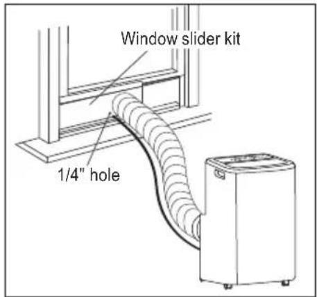
There is a 1/4" hole on the window kit for leading the drainage hose outside during the heating mode.
Do not drain condensate outside when outside temperature is below 32^ F ( 0^ C).
Figure 24
Emptying the condensate residue inside the unit during winter storage.
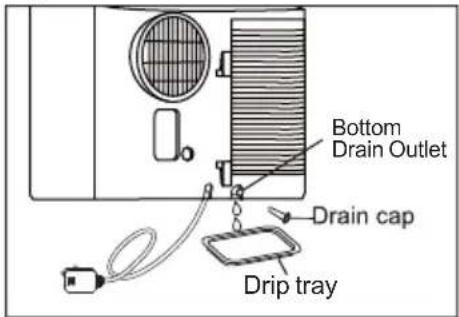
Put a drip tray (not supplied) under the continuous drain outlet, then unscrew the drain cap to allow the condensate to flow into the drip tray. Replace the drain cap to the continuous drain outlet when no condensate flows out.
Put the drip tray under the bottom drain outlet, then remove the rubber stopper from the drain outlet, to allow the condensate to flow into the drip tray. If your drip tray can't hold all the condensate, a number of fills will be needed.
Replace the drain cap to the bottom drain outlet when no condensate flows out.
Note: To ensure all condensate residue has been removed, tilt the unit by lifting it slightly upwards from the front until no more condensate comes out from the drain outlet.
Figure 25
Cleaning
Clean your air conditioner occasionally to keep it looking new. Be sure to unplug the unit before cleaning to prevent shock or fire hazards.
CLEANING THE UNIT
The cabinet and front may be dusted with an oil-free cloth or washed with a cloth dampened in a solution of warm water and mild liquid dishwashing detergent.
Never use harsh cleaners, wax or polish on the cabinet front.
Be sure to wring excess water from the cloth before wiping around the controls. Excess water in or around the controls may cause damage to the air conditioner.
CLEANING THE FILTERS
To keep your air conditioner working efficiently, you should clean the filters every week of operation.
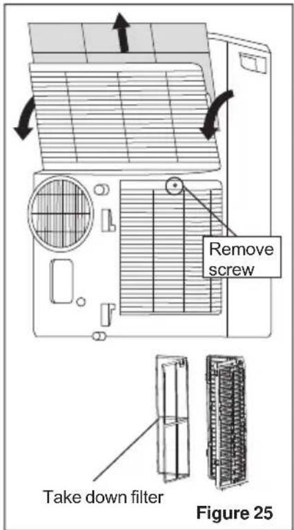
This unit has two filters, they are filter A and B. Grasp the upper panel tab and take off the filter A which behind the grill of the back panel (Fig.25). Remove the lower filter B by loosening the screw. Take down the air inlet grille, then remove the air filter as shown in Fig.25.
Wash the filter using liquid dishwashing detergent and warm water. Rinse filter thoroughly. Gently shake excess water from the filter. Be sure filter is thoroughly dry before replacing.
Or, instead of washing you may vacuum the filter clean.
Replace the filter after the filter is dry.
Winter Storage
If the air conditioner will not be used for an extended period of time:
- Drain the water collection tank completely and leave the bottom drain cap and rubber plug long time enough to allow any residual water to drain out. Once the tank is completely drained and no more water flows out, reinstall the rubber plug and cap.
- Remove and clean the filter, allow it to dry completely, then reinstall it.
- Remove the batteries from the remote control.
- Store the air conditioner in a cool, dry location, away from direct sunlight, extreme temperature, and excessive dust.
Before using the air conditioner again:
- Make sure the filter and drain cap are in place.
- Check the cord to make sure it is in good condition, without cracks or damage.
- Place new batteries in the remote control.
- Install the air conditioner as described in the Installation Instructions.
Before calling for service, review this list. It may save you time and expense. This list includes common occurrences that are not the result of defective workmanship or materials in this appliance.
| OCCURRENCE | SOLUTION |
| Air conditioner will not operate. | Wall plug disconnected. Push plug firmly into wall outlet. |
| Plug Current Device Tripped. Press the RESET button. | |
| House fuse blown or circuit breaker tripped. Replace fuse with time delay type or reset circuit breaker. | |
| Control is OFF. Turn Control ON and set to desired setting. | |
| P1 appears in the display window. Drain water as described in Drainage Section. | |
| Shut off in Heat mode. When the air outlet exceeds 158 °F (70 °C), the automatic heat protection engages. Remove any blockages and let appliance cool down. | |
| Room Temperature lower than the set temperature (Cool Mode). Reset the temperature. | |
| Room Temperature higher than the set temperature (Heat Mode). Reset the temperature. | |
| Air from unit does not feel cold enough. | Room temperature below 60°F (16°C). Cooling may not occur until room temperature rises above 60°F (16°C). |
| Reset to a lower temperature. | |
| Compressor shut-off by changing modes. Wait approximately 3 minutes and listen for compressor to restart when set in the COOL mode. | |
| Air conditioner cooling, but room is too warm - ice forming on cooling coil behind decorative front | Outdoor temperature below 60 °F (16 °C). To defrost the coil, set FAN ONLY mode. |
| Air filter may be dirty. Clean filter. Refer to Care and Cleaning section. To defrost, set to FAN ONLY mode. | |
| Temperature is set too low for night-time cooling. To defrost the coil, set to FAN ONLY mode. Then, set temperature to a higher setting. | |
| Exhaust duct not connected or blocked. See EXHAUSTING HOT AIR Section. | |
| Air conditioner cooling, but room is too warm - NO ice forming on cooling coil behind decorative front. | Dirty air filter - air restricted. Clean air filter. Refer to Care and Cleaning section. |
| Temperature is set too high. Set temperature to a lower setting. | |
| Air directional louvers positioned improperly. Position louvers for better air distribution. | |
| Front of unit is blocked by drapes, blinds, furniture, etc. - restricts air distribution. Clear blockage in front of unit. | |
| Doors, windows, registers, etc. open - cool air escapes. Close doors, windows, registers, etc. | |
| Unit recently turned on in hot room. Allow additional time to remove "stored heat" from walls, ceiling, floor and furniture. | |
| Air conditioner turns on and off rapidly. | Dirty air filter - air restricted. Clean air filter. |
| Outside temperature extremely hot. Set FAN speed to a faster setting to bring air through cooling coils more frequently. | |
| Noise when unit is cooling. | Air movement sound. This is normal. If too loud, set to lower FAN setting. |
| Vibraion from uneven floor. Move or support appliance correctly on even surface. | |
| Room too cold. | Set temperature too low. Increase set temperature. |
| Room Too Hot. | Set temperature too high. Lower setting. |
If These Solutions Fail, Call 1-800-944-9044(US)/1-800-265-8352(Canada) For Frigidaire Service.
Major Appliance Limited Warranty
Your appliance is covered by a limited one-year warranty for functional repairs only. For one year from your original date of purchase, Electrolux will pay all costs for repairing or replacing any parts of this appliance that prove to be defective in materials or workmanship when such appliance is installed, used and maintained in accordance with the provided instructions. After one year from your original date of purchase, the consumer will be responsible for diagnostic, labor and parts costs as well as any removal, transportation and reinstallation expenses which are incurred during service on components.
Exclusions This warranty does not cover the following:
- Products with original serial numbers that have been removed, altered or cannot be readily determined.
- Product that has been transferred from its original owner to another party or removed outside the USA or Canada.
- Rust on the interior or exterior of the unit.
- Products purchased "as-is" are not covered by this warranty.
- Food loss due to any refrigerator or freezer failures.
- Products used in a commercial setting.
- Service calls which do not involve malfunction or defects in materials or workmanship, or for appliances not in ordinary household use or used other than in accordance with the provided instructions.
- Service calls to correct the installation of your appliance or to instruct you how to use your appliance.
- Expenses for making the appliance accessible for servicing, such as removal of trim, cupboards, shelves, etc., which are not a part of the appliance when it is shipped from the factory.
- Service calls to repair or replace appliance light bulbs, air filters, water filters, other consumables, or knobs, handles, or other cosmetic parts.
- Surcharges including, but not limited to, any after hour, weekend, or holiday service calls, tolls, ferry trip charges, or mileage expense for service calls to remote areas, including the state of Alaska.
- Damages to the finish of appliance or home incurred during installation, including but not limited to floors, cabinets, walls, etc.
- Damages caused by: services performed by unauthorized service companies; use of parts other than genuine Electrolux parts or parts obtained from persons other than authorized service companies; or external causes such as abuse, misuse, inadequate power supply, accidents, fires, or acts of God.
DISCLAIMER OF IMPLIED WARRANTIES; LIMITATION OF REMEDIES
CUSTOMER'S SOLE AND EXCLUSIVE REMEDY UNDER THIS LIMITED WARRANTY SHALL BE PRODUCT REPAIR OR REPLACEMENT AS PROVIDED HEREIN. CLAIMS BASED ON IMPLIED WARRANTIES, INCLUDING WARRANTIES OF MERCHANTABILITY OR FITNESS FOR A PARTICULAR PURPOSE, ARE LIMITED TO ONE YEAR OR THE SHORTEST PERIOD ALLOWED BY LAW, BUT NOT LESS THAN ONE YEAR. ELECTROLUX SHALL NOT BE LIABLE FOR CONSEQUENTIAL OR INCIDENTAL DAMAGES SUCH AS PROPERTY DAMAGE AND INCIDENTAL EXPENSES RESULTING FROM ANY BREACH OF THIS WRITTEN LIMITED WARRANTY OR ANY IMPLIED WARRANTY. SOME STATES AND PROVINCES DO NOT ALLOW THE EXCLUSION OR LIMITATION OF INCIDENTAL OR CONSEQUENTIAL DAMAGES, OR LIMITATIONS ON THE DURATION OF IMPLIED WARRANTIES, SO THESE LIMITATIONS OR EXCLUSIONS MAY NOT APPLY TO YOU. THIS WRITTEN WARRANTY GIVES YOU SPECIFIC LEGAL RIGHTS. YOU MAY ALSO HAVE OTHER RIGHTS THAT VARY FROM STATE TO STATE.
If You Need Service Keep your receipt, delivery slip, or some other appropriate payment record to establish the warranty period should service be required. If service is performed, it is in your best interest to obtain and keep all receipts. Service under this warranty must be obtained by contacting Electrolux at the addresses or phone numbers below.
This limited warranty only applies in the USA and Canada. In the USA, your appliance is warranted by Electrolux Major Appliances North America, a division of Electrolux Home Products, Inc. In Canada, your appliance is warranted by Electrolux Canada Corp. Electrolux authorizes no person to change or add to any obligations under this warranty. Obligations for service and parts under this warranty must be performed by Electrolux or an authorized service company. Product features or specifications as described or illustrated are subject to change without notice.
USA
1.800.944.9044
Electrolux Major Appliances
10200 David Taylor Drive
Charlotte, NC 28262

Electrolux
Canada
1.800.265.8352
Electrolux Canada Corp.
5855 Terry Fox Way
Mississauga, Ontario, Canada
L5V 3E4
- TABLE OF CONTENTS
- Important Safety Instructions
- NOTE:
- WARNING
- For Your Safety
- Prevent Accidents
- Electrical Information
- SAFETY PRECAUTIONS
- DANGER! Avoid Serious Injury or Death
- CAUTION! Avoid Injury or damage to the unit or other property
- READ THIS SECTION BEFORE ATTEMPTING TO OPERATE AIR CONDITIONER. Unit must be upright for one hour prior to operating.
- Operation of Current Device
- CAUTION
- Product Registration & Normal Sounds
- Product Registration
- Record Your Model and Serial Numbers
- Register Your Product
- Normal Sounds
- Installation Instructions
- EXHAUSTING HOT AIR
- Installation Instructions(continued)
- Installation in a double-hung sash window
- Installation in a sliding sash window
- Air Conditioner Features & Operating Instructions
- Operating Instruction
- Cool mode
- Dry mode
- Fan mode
- Heat mode(For Heat & Cool models only)
- AUTO mode
- Timer mode
- How to delay startup
- How to delay shutdown
- Sleep mode
- Louver Swing Function
- Filter reset
- °F /°C function
- Remote Control
- Battery Installation and Important Instructions
- How to Use the Remote Control
- TURNING THE UNIT ON
- Operating Instructions
- Fault Code
- Drainage Instructions
- Continuous Drainage
- NOTE
- Heat pump Drainage(For heating & cooling model only)
- Emptying the condensate residue inside the unit during winter storage.
- Cleaning
- CLEANING THE UNIT
- CLEANING THE FILTERS
- Winter Storage
- Major Appliance Limited Warranty
- Exclusions This warranty does not cover the following:
- DISCLAIMER OF IMPLIED WARRANTIES; LIMITATION OF REMEDIES
Brand : FRIGIDAIRE
Model : FHPH132AB1
Category : Air conditioner