
G2 - Access Control System ZKTeco - Free user manual and instructions
Find the device manual for free G2 ZKTeco in PDF.


| Product Type | Access Control System with Fingerprint and Facial Recognition |
| Model | G2 |
| Brand | ZKTeco |
| Verification Modes | 1:N Fingerprint, 1:1 Fingerprint, Password, ID Card (optional), Facial |
| Fingerprint Capacity | Up to 20,000 templates |
| User Capacity | Up to 30,000 users |
| Attendance Record Capacity | Up to 200,000 records |
| Display | Color TFT screen |
| Communication | Ethernet (TCP/IP), RS232/RS485, USB Host, optional Wi-Fi and 3G/GPRS |
| Wiegand Support | Input and Output (26-bit, 34-bit) |
| Power Supply | 12V DC |
| Operating Temperature | 0°C to 45°C (estimated) |
| Operating Humidity | 20% to 80% (estimated) |
| Key Features | Voice prompts, bell schedules, short messages, work codes, anti-passback, duress alarm, auto test, USB upgrade, data backup/restore |
| Security | Live finger detection, fingerprint characteristic points only (no image stored), password protection |
| Environmental Protection | RoHS compliant, Environment-Friendly Use Period (EFUP) marked |
| Firmware Upgrade | Via USB flash drive |
Frequently Asked Questions - G2 ZKTeco
User questions about G2 ZKTeco
0 question about this device. Answer the ones you know or ask your own.
Ask a new question about this device
Download the instructions for your Access Control System in PDF format for free! Find your manual G2 - ZKTeco and take your electronic device back in hand. On this page are published all the documents necessary for the use of your device. G2 by ZKTeco.
USER MANUAL G2 ZKTeco
Applicable Models: G2
Version: 1.0
Important Claim
Firstly thank you for purchasing this facial and fingerprint hybrid terminal, before use, please read this manual carefully to avoid the unnecessary damage! The company reminds you that the proper user will improve the use affect and authentication speed.
No written consent by our company, any unit or individual isn't allowed to excerpt, copy the content of this manual in part or in full, also spread in any form.
The product described in the manual maybe includes the software which copyrights are shared by the licensors including our company, Except for the permission of the relevant holder, any person can't copy, distribute, revise, modify, extract, decompile, disassemble, decrypt, reverse engineering, leasing, transfer, sub-license the software, other acts of copyright infringement, but the limitations applied to the law is excluded.

Due to the constant renewal of products, the company cannot undertake the actual product in consistence with the information in the document, also any dispute caused by the difference between the actual technical parameters and the information in this document. Please forgive any change without notice.
Contents
Contents....I
1 Instruction for Use....1
1.1 Finger Placement....1
1.2 Verification Modes....1
1.2.1 1: N Fingerprint Verification....1
1.2.2 1:1 fingerprint verification....1
1.2.3 Password Verification .... 2
1.2.4 ID Card Verification....3
1.3 Status of icons....4
2 Main Menu 5
3 User Management 7
3.1. Adding a User ....7
3.1.1 Entering a User ID 7
3.1.2 Modifying the user role....8
3.1.3 Enrolling a Fingerprint....8
3.1.4 Enrolling an ID Card 9
3.1.5 Enrolling a Password....9
3.1.6 Enroll Photo....9
3.1.7 Access Control Role....9
3.2 Query a User in All User....11
3.2.1 Query by User ID and Name 11
3.2.2 Edit and delete a User 12
3.3 Display Style....12
4 User Role 14
5 Communication Setting....15
5.1 Ethernet....15
5.2 Serial Comm★....16
5.3 PC Connection....16
5.4 Cellular Data Network★....16
5.5 Wireless Network★ 17
5.6 ADMS★....18
5.7 Wiegand Setup....19
5.7.1 Wiegand INput....19
5.7.2 Wiegand OUTput....19
6 System....21
6.1 Date/Time 21
6.2 Attendance 23
6.3 Fingerprint....24
6.4 Reset....25
6.5 USB Upgrade....25
7 Personalize....26
7.1 User Interface 26
7.2 Voice....27
7.3 Bell Schedules 27
7.4 Punch State Options....29
7.5 Shortcut Key Mappings....30
8 Data Mgt....31
8.1 Delete Data....31
8.2 Backup Data....32
8.3 Restore Data....32
9 Access Control Setting....34
9.1 Access Control Options....34
9.2 Time Schedule....35
9.3 Holiday setting....36
9.4 Access Groups....37
9.5 Set Combined Verification....39
9.6 Anti-pass back 40
9.7 Duress alarm parameter....40
10 USB Manager 42
10.1 Download....42
10.2 Upload 43
10.3 Download Options....43
11 Attendance Search....44
12 Print★ 45
12.1 Data Field Setup....45
12.2 Printer Options....45
13 Short Message....46
13.1 Public, Personal and Drafts lists....46
13.2 Message Options....46
13.3 Employee check SMS 47
14 Work Code....48
14.1 Add a work code ....48
14.2 All Work Codes 49
14.3 work code Options....49
15 AutoTest 50
16 System Information....51
Appendix 52
Appendix 1 Description of Text Input Operation....52
Appendix 2 Image Upload Rules....52
Appendix 3 anti-pass back....53
Statement on Human Rights and Privacy....55
Environment-Friendly Use Description....56
1 Instruction for Use
1.1 Finger Placement
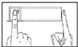
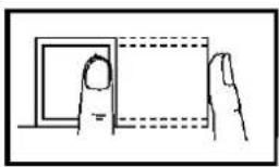
Recommended fingers: The index finger, middle finger or the ring finger; the thumb and little finger are not recommended (because they are usually clumsy on the fingerprint collection screen).
1) Proper finger placement: The finger is flat to the surface and centered in fingered guide.
natural_image
Illustration of two hands pointing at a rectangular object with dashed lines indicating alignment or measurement (no text or symbols)2) Improper finger placement: Not flat to the surface, off-centre, slanting.
natural_image
Simple line drawing of a hand holding a rectangular object with dashed lines indicating hidden edges (no text or symbols)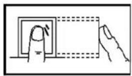
natural_image
Illustration of a hand pressing a button on a square panel (no text or symbols)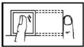
natural_image
Simple line drawing of a hand pressing a button on a screen (no text or symbols)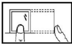
1.2 Verification Modes
1.2.1 1: N Fingerprint Verification
The terminal compares current fingerprint collected by the fingerprint collector with all fingerprint data on the terminal.
Press your finger on the fingerprint collector by adopting the proper finger placement. For details, see 1.1 Finger Placement.
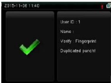
When verification successful, an interface shown above.
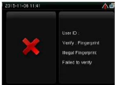
When verification failed, an interface shown above.
1.2.2 1:1 fingerprint verification
In the 1:1 fingerprint verification mode, the terminal compares current fingerprint collected through the fingerprint collector with that in relation to the user ID entered through keyboard. Adopt this mode only when
it is difficult to recognize the fingerprint.
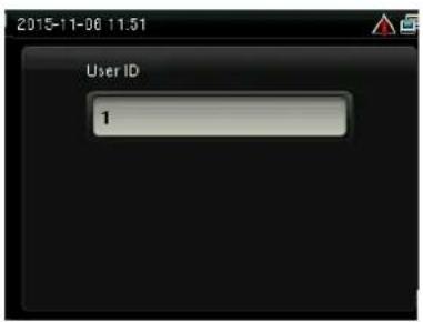
Enter the user ID using keypad on the initial interface. Then press OK. Place the enrolled finger properly on the fingerprint sensor.
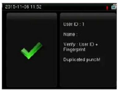
When verification successful, an interface shown above.
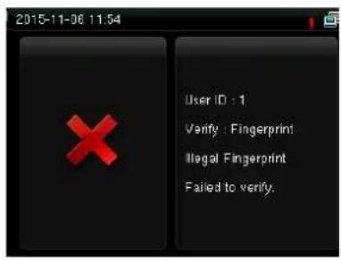
When verification failed, an interface shown above.
Notes:
- If it says that the enroll number is wrong, it means that there is no such number or the employee doesn't enroll password.
- If the device says "Please press again", place the finger on the fingerprint sensor again. You can try another 2 times by default. The repeated times can be set in 6.3 Fingerprint. If it fails after 2 times, return Step 1 for second operation.
1.2.3 Password Verification
In the password verification mode, the terminal compares the password entered with that in relation to the user ID.
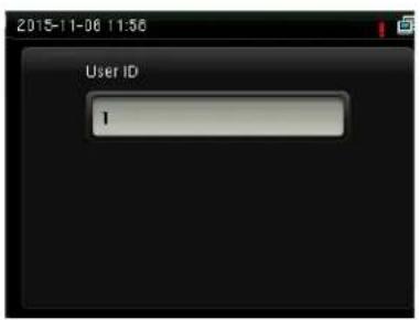
Enter the user ID using keypad on the initial interface. Then press OK.
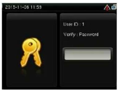
Enter password and press OK.
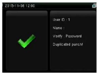
When verification successful, an interface shown above.
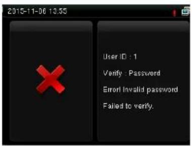
When verification failed, an interface shown above.
Notes: If the device says "Invalid ID", enter the password again. You can try another 2 times by default. The repeated times can be set in6.3 Fingerprint. If it fails after 2 times, return Step 1 for second operation.
1.2.4 ID Card Verification
Only the products with a built-in ID card module support the ID card verification. The products with a built-in ID card module support the following two verification modes:
ID Card Only: Users only need to swipe their ID cards for verification.
ID + Finger Verification: After passing the ID card verification, you also need to perform finger verification.
1. ID Card Only
1) If you have your ID card number enrolled in the system, you can pass the verification by swiping your ID card at the swiping area in a proper way.
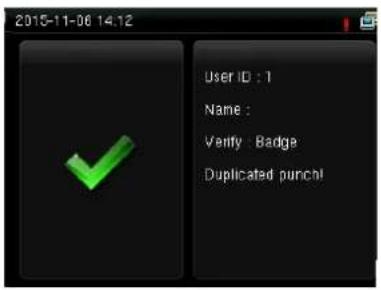
If the verification is successful, an interface as shown above.
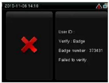
If the verification is not successful, an interface as shown above.
2. ID + Facial Verification
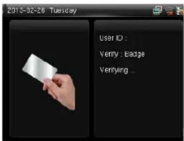
Swipe your ID card properly at the swiping area to enter the 1:1 facial verification mode.
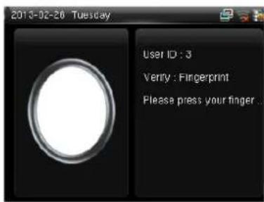
Place the enrolled finger properly on the fingerprint sensor.
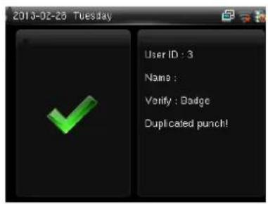
If the verification is successful, an interface as shown above.
1.3 Status of icons
| Status Icon | Name | Description |
 | Cell signal | The status icons indicate whether you are within the coverage of the cellular mobile network, with more green bars indicating stronger signal. |
 | ||
 | G: indicates that the current mobile network is GPRS network★, over which the device accesses the Internet. | |
 | ||
 | E: indicates that the operator's EDGE (GSM) network is available, over which the device accesses the Internet. | |
 | ||
 | W: indicates that the current mobile network is WCDMA network, over which | |
 | Indicates that no mobile network is available. | |
 | Bell | Indicates that you have set the bell. |
 | Indicates that a disassembly alarm. | |
 | Ethernet | Indicates that the connection to Ethernet has been established. |
 | Indicates that the Ethernet is disconnected. | |
 | ADMS Server | The connection between device and ADMS server is successful. |
 | The connection between device and ADMS server is failed. | |
 | The communication data of ADMS are transmitting. | |
 | Short Messages | There are public short messages. |
 | Wi-Fi signal | The Wi-Fi★ connection is normal. |
 | The Wi-Fi★ connection fails. |
2 Main Menu
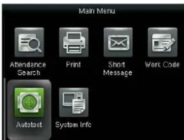
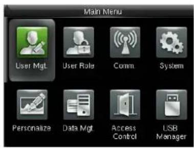
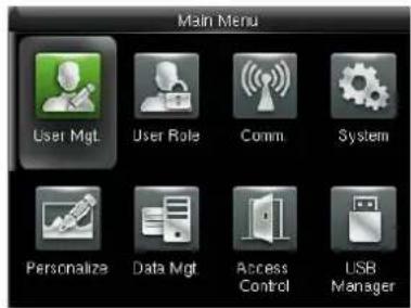
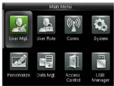
When the device is on initial interface, press M/OK to open main menu, as shown below:
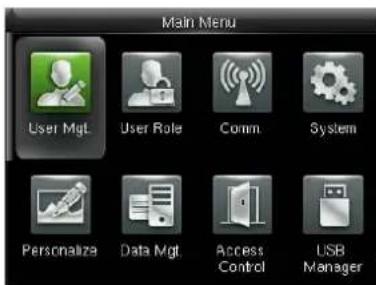
User Mgt.: You can browse the user information stored on the terminal, including the user ID, name, user role, fingerprint, badge number, card, password, user photo, add, modify or delete the user information.
User Role: used to set the rights of a user-defined role, that is, rights to menus.
Comm. Settings: You can set related parameters for communication between the terminal and PC, including the IP address, Gateway, Subnet Mask, Baud Rate, Device ID and Comm. Key and so on.
System: You can set system-related parameters, including the Date Time, Attendance, Fingerprint, Camera, Reset and USB Upgrade, to enable the terminal to meet user requirements to the greatest extent in terms of functions and display.
Personalize: used to meet user requirements to the greatest extent regarding display, audio, ringing, and keyboard definition.
Data Mgt.: You can perform management of data stored on the terminal, for example, Delete Data, Backup Data and Restore Data.
Access Control: You can set the parameters of the electronic locks and related access control devices.
USB Manager: You can import user information and attendance data stored in a USB disk to related software or other fingerprint recognition equipment.
Attendance Search: For query the record saved in the device, query record function is provided.
Print ★: used to determine whether to print attendance records immediately.
Short Message: used to set a public or private short message. The short message will be displayed to a specified person in the specified time after work attendance check, which facilitates information transfer.
Work Code: used to identify different work types, which facilitates work attendance check.
Autotest: This submenu enables the system to automatically test whether functions of various modules are normal, including the Screen, Fingerprint, Voice, Keyboard and Time.
System Info: To check the current device capacity, device information and its firmware information.
Menu Tree
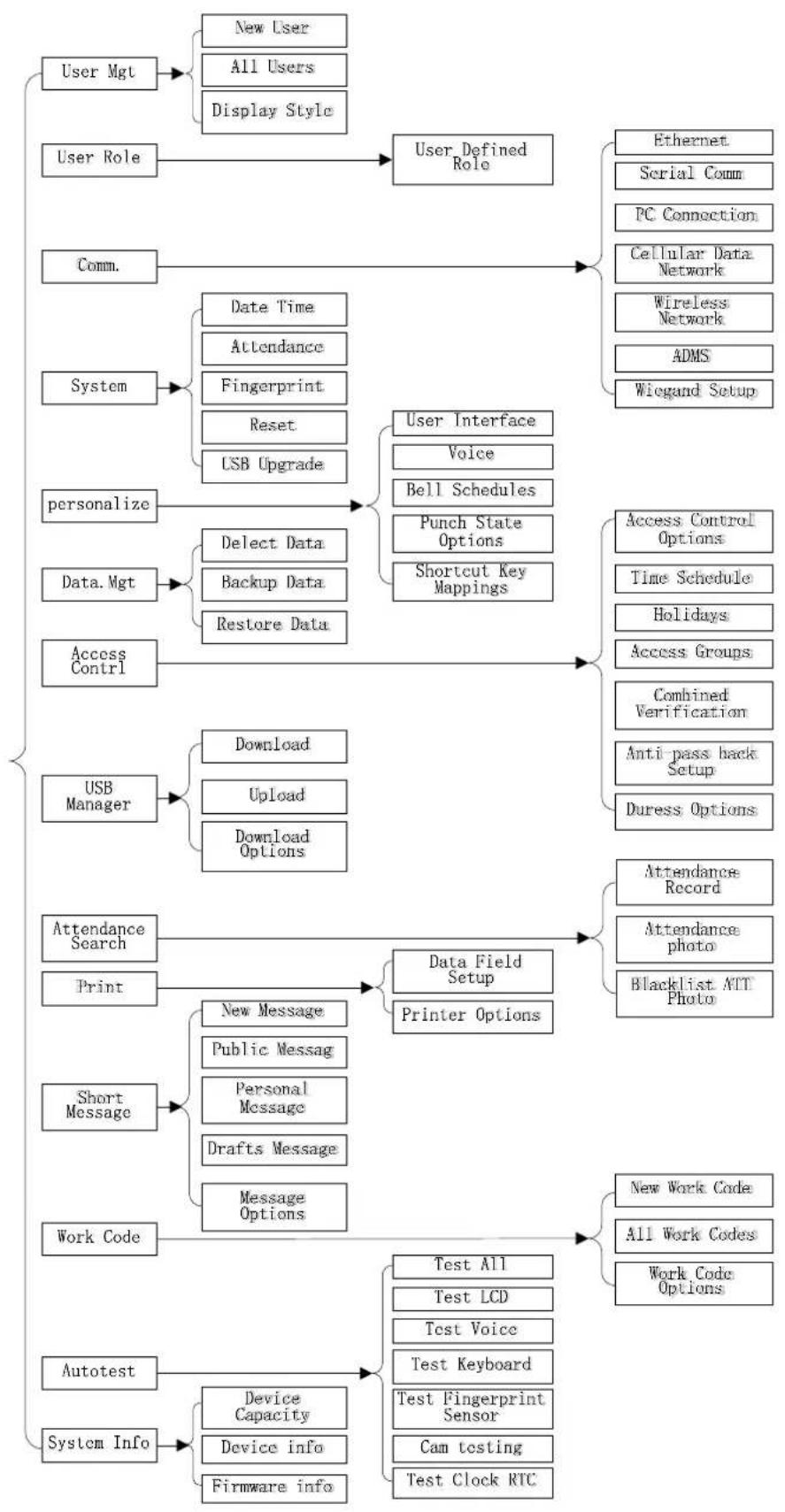
flowchart
graph TD
    A["User Mgt"] --> B["New User"]
    A --> C["All Users"]
    A --> D["Display Style"]
    E["User Role"] --> F["User Defined Role"]
    G["Comm."] --> H["Ethernet"]
    G --> I["Serial Comm"]
    G --> J["PC Connection"]
    G --> K["Cellular Data Network"]
    G --> L["Wireless Network"]
    G --> M["ADMS"]
    G --> N["Wiegand Setup"]
    O["System"] --> P["Date Time"]
    O --> Q["Attendance"]
    O --> R["Fingerprint"]
    O --> S["Reset"]
    O --> T["USB Upgrade"]
    U["personalize"] --> V["User Interface"]
    U --> W["Voice"]
    U --> X["Bell Schedules"]
    U --> Y["Punch State Options"]
    U --> Z["Shortcut Key Mappings"]
    AA["Data.Mgt"] --> AB["Delect Data"]
    AA --> AC["Backup Data"]
    AA --> AD["Restore Data"]
    AE["Access Control"] --> AF["Access Control Options"]
    AE --> AG["Time Schedule"]
    AE --> AH["Holidays"]
    AE --> AI["Access Groups"]
    AJ["USB Manager"] --> AK["Download"]
    AJ --> AL["Upload"]
    AJ --> AM["Download Options"]
    AN["Attendance Search"] --> AO["Data Field Setup"]
    AN --> AP["Printer Options"]
    AQ["Print"] --> AR["New Message"]
    AQ --> AS["Public Messag"]
    AQ --> AT["Personal Message"]
    AQ --> AU["Drafts Message"]
    AQ --> AV["Message Options"]
    AW["Short Message"] --> AX["New Message"]
    AW --> AY["Public Messag"]
    AW --> AZ["Personal Message"]
    AW --> BA["Drafts Message"]
    AW --> BB["Message Options"]
    BC["Work Code"] --> BD["Test All"]
    BC --> BE["Test LCD"]
    BC --> BF["Test Voice"]
    BC --> BG["Test Keyboard"]
    BC --> BH["Test Fingerprint Sensor"]
    BC --> BI["Cam testing"]
    BC --> BJ["Test Clock RTC"]
    BK["Autotest"] --> BL["Device Capacity"]
    BK --> BM["Device info"]
    BK --> BN["Firmware info"]
3 User Management
Through this submenu, you can browse the user information stored on the terminal, including the user ID, name, user role, fingerprint, badge number, card, password, user photo; add, modify or delete the user information. In company's attendance management, for employee's change, the information on fingerprint sensor also needs modification. Therefore, operations including "add, delete, check, modify and so on" can be done on fingerprint sensor.
3.1 Adding a User
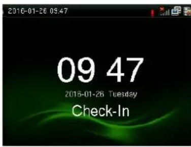
Press M/OK key on the initial interface.
Select Users and press OK.
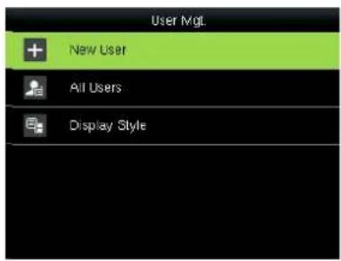
Select New User and press OK.
3.1.1 Entering a User ID
The terminal automatically allocates an ID starting from 1 for every user in sequence. If you use the ID allocated by the terminal, you may skip this section.
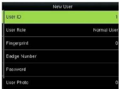
Select User ID and press OK.
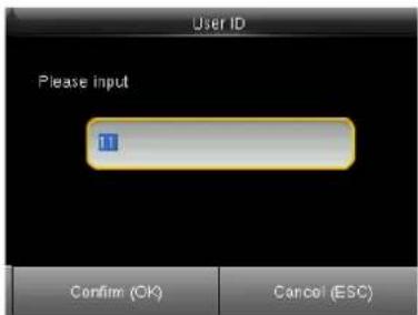
Enter the user ID using keypad then press OK.
Tip: The terminal supports the 1- to 9-digit user IDs by default.
If a prompt message "The user ID already exists!" is displayed, enter another ID.
3.1.2 Modifying the user role
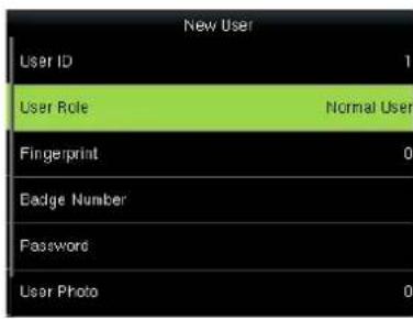
Press ▼ to select role.
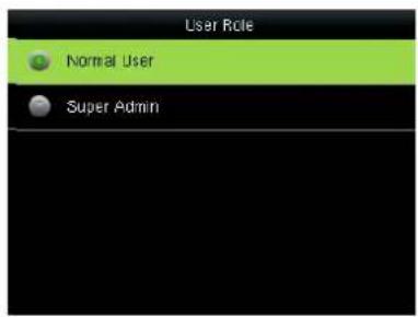
Select the role.
Super Admin: The super administrator has the operation rights to all menu functions.
Normal user: If the system has an administrator, a common user is entitled only to authentication using his/her fingerprint, password, or card. If the system does not have an administrator, a common user has the operation rights to all menu functions.
User Defined Role: A user-defined role can be assigned some other menu functions in addition to the functions available for a common user. (When logging in as a super administrator, you have the rights to assign menu functions to a customized role.)
3.1.3 Enrolling a Fingerprint
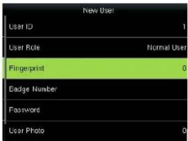
Press ▼ to select Fingerprint and press OK.
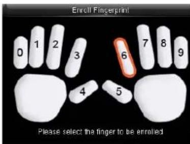
Place your finger on the fingerprint sensor properly.
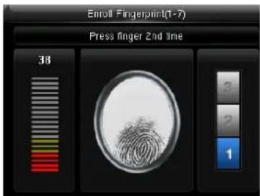
Place the same finger on the fingerprint sensor for three times.
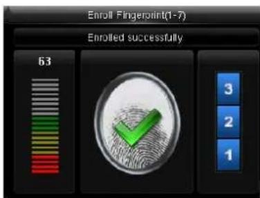
Enrollment succeeds. If the enrollment fails, the system will display a prompt message and return to the [Enroll Fingerprint] interface. In this case, you need to repeat the operations of step 2.
3.1.4 Enrolling an ID Card
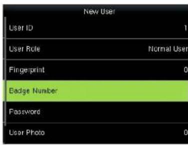
Press ▼ to select Badge Number and press OK.
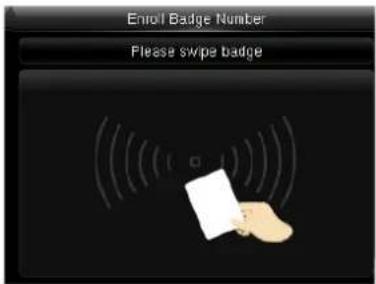
Swipe your ID card properly in the swiping area.
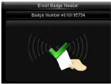
Read Successfully!
3.1.5 Enrolling a Password
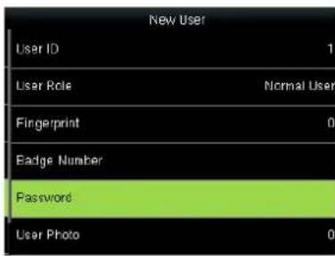
Press ▼ to select Password and press OK.
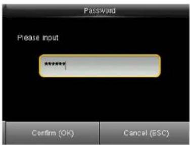
Enter a password using keypad then press OK..The FFR terminal supports the 1- to 8-digit passwords by default.
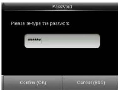
Re-enter the password according to the system prompt and then press OK.
3.1.6 Enroll Photo
If you have enrolled your photo in the system, the system will display your enrolled photo in addition to your ID and name after you pass the verification.
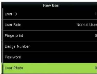
Press ▼ to select User Photo and press OK.
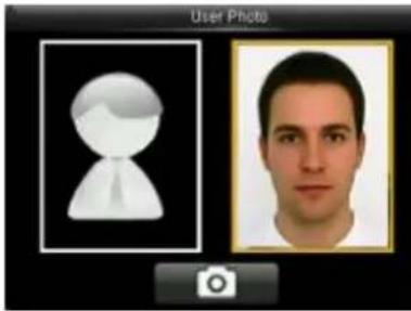
Stand naturally in front of the screen. Press OK
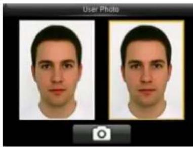
natural_image
Two identical male face portraits displayed side by side, no text or symbols presentPress ESC to directly return to previous interface
3.1.7 Access Control Role
User access control option is to set open door access aimed at everybody, including subgroup setting, verification mode, using time zone, duress fingerprint management.
Access group: Allocate enrolled user to different groups for management convenience.
Verification mode:
1) Group verification type: Whether the user use his group's verification type
2) Individual verification type: Select the user's verification type. If group verification type is not used, others' verification type won't be affected.
Duress Fingerprint: User enrolls a new fingerprint or specifies an enrolled fingerprint in the fingerprint sensor as duress fingerprint. At any time anywhere, duress alarm will generate after the fingerprint passes verification.
Apply Group Time Period:
1) Select "ON", group time zone, the user use his group's default time zone.
2) Select "OFF", set user unlocking time. If group time zone is not used, others' unlocking time will not be affected.
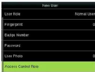
Press ▼ to select Access Control Role and press OK.
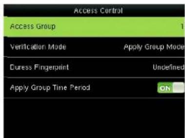
Press OK enter to Access Group interface
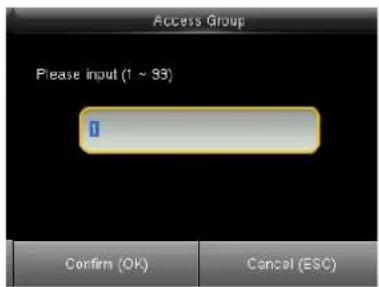
Enter the user group using keypad then press OK to return.
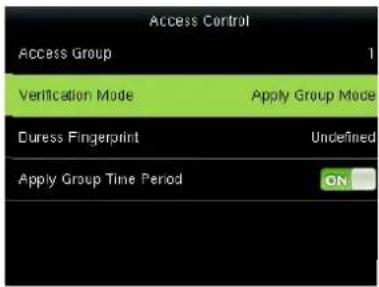
Press ▼ to select verification mode and press OK.
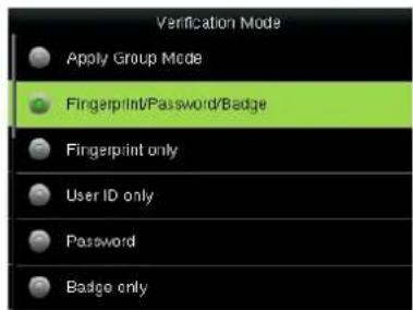
Press to select verification type and press OK.
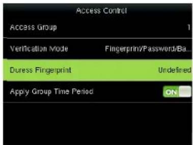
Press to select Duress Fingerprint and press OK.
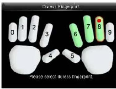
Press ◀/▶ to select enrolled fingerprint and press OK.
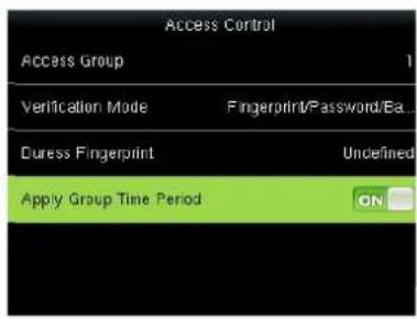
Press ▼ to select Apply Group Time Period, press OK to select to whether the user use his group's default time zone.
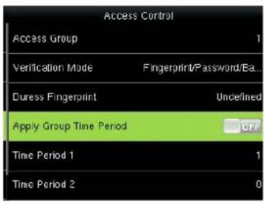
When select "OFF" Press to select Time period 1.
3.2 Query a User in All User
To facilitate administrators to locate a user quickly from a large number of enrolled users, the FFR terminal enables user query by his/her "User ID" and "Name". (Location Search)
Press M/OK on the initial interface.
Select Users and press OK.

Press ▼ to Select All User and press OK.
3.2.1 Query by User ID and Name
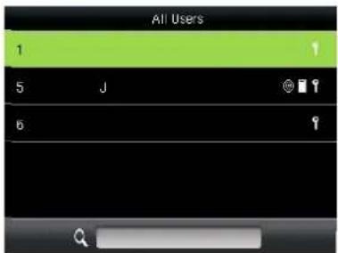
Enter the user ID using keypad to query to view all users.
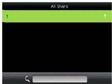
The cursor to the user to be queried.
Press # on the search interface to change an input method and press letter keys of the numeric keyboard to search by name.
3.2.2 Edit and delete a User
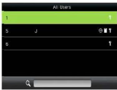
Press ▼ to select a User and press OK.
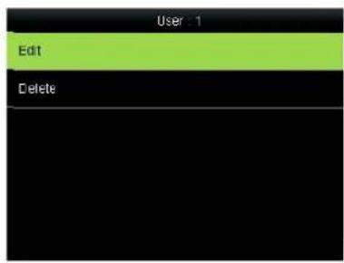
Press OK to enter User Info interface.
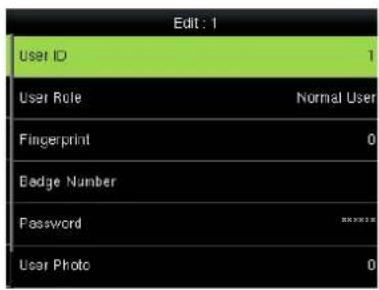
The User ID cannot be modified, and the other operations are similar to those performed to add a user.
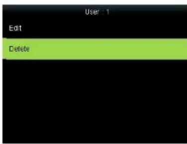
Press ▼ to select Delete and press OK.
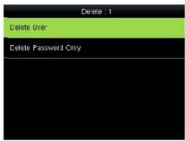
Press ▼ to select item need delete and press OK.
Other user-defined administrators are cleared when user rights are deleted.
3.3 Display Style
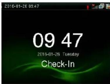
Press M/OK on the initial interface.
Select Users and press OK.
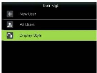
Press ▼ to Select Display Style and press OK.
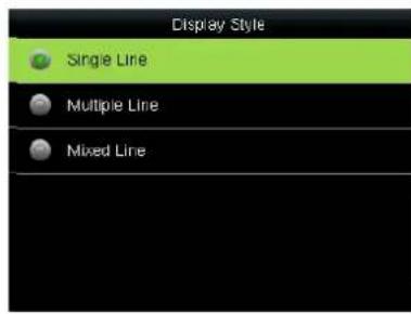
Press ▼ to select display style and press OK to return.
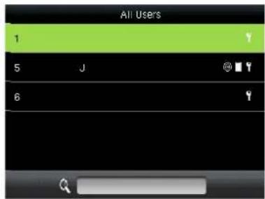
Single Line
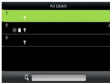
Multiple line
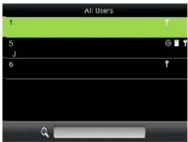
Mixed Line
4 User Role
Set the rights of a user-defined role, that is, rights to menus.
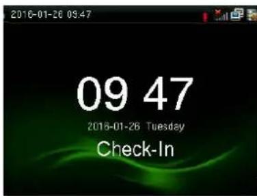
Press M/OK on the initial interface.
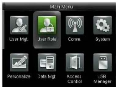
Press ▶ to select User Role and press OK.
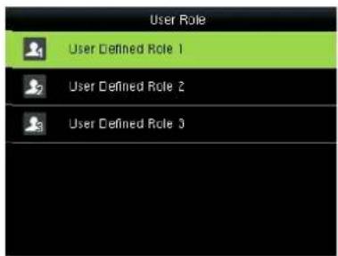
Press ▼ to select User Defined Role 1 and press OK.
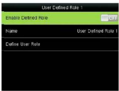
Press OK to open.
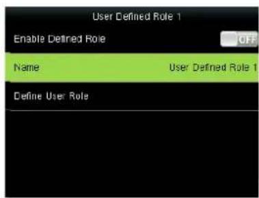
Press ▼ to Select Name and press OK.
![Name Please input User Defined Role 1 Right key to switch input method, Left key to back space [As]](/content/2026/05/949767/images/872688030468316a408aba831b9e89a8af208d3d54fed3ad3d3f0f33d5ebc1bb.jpg)
Press * to switch input method and enter the Name, press OK.
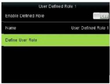
Press ▼ to▼ select Define User Role and press OK
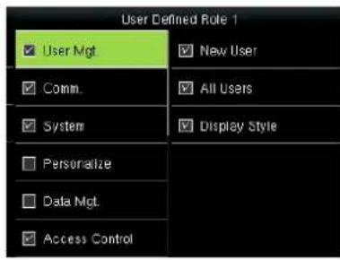
Press and OK to select rights. Press ESC to exit.
5 Communication Setting
Set parameters for communication between the device and a PC. The parameters include the IP address, gateway, subnet mask, baud rate, machine ID, and login password.
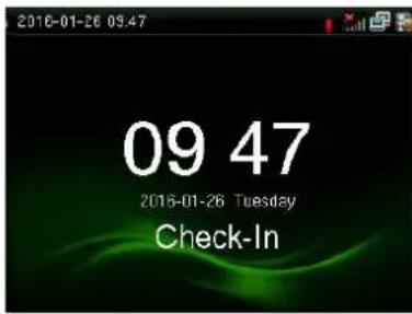
Press M/OK on the initial interface.
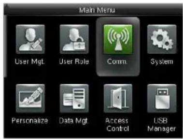
Press ▶ to COMM. Settings and press OK.
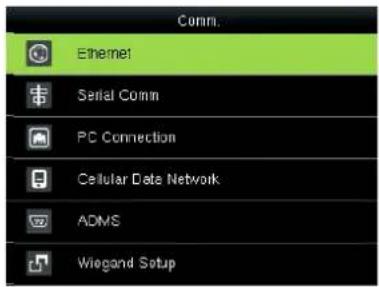
Select Ethernet and press OK.
5.1 Ethernet
When Ethernet is used for communication of device and PC, the following settings need to be checked:
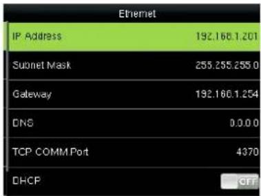
IP Address: IP is 192.168.1.201 by default. You can modify it if it is necessary. But it cannot be the same with that of PC.
Subnet Mask: It is 255.255.255.0 by default. You can modify it if it is necessary.
Gateway: It is 0.0.0.0 by default. If the device and PC are in different net segment, it is necessary to set address.
DNS: The DNS Server is 0.0.0.0 by default and can be changed as required.
TCP COMM Port: It is 4730 by default. You can modify it if it is necessary.
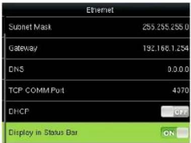
DHCP: short for Dynamic Host Configuration Protocol, which is used by a server to allocate dynamic IP addresses to clients on a network
Display in Status Bar: used to set whether to display network icons in the status bar of the main interface.
5.2 Serial Comm★
When serial port (RS232/RS485) is used for communication of device and PC, the following settings need to be checked:
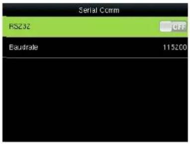
RS232: Whether use RS232 to communicate. Select "Yes" if RS232 is to be used.
Baudrate: Used for communication with PC. There are five options: 9600, 19200, 38400, 57600 and 115200. If the communication speed is high, RS232 is recommended. If the communication speed is low, RS 485 is recommended.
5.3 PC Connection
To improve the security of attendance data, connection password needs to be set here. Connection password must be input when PC software is to connect device to read data.
Comm Key: System password is 0 by default.(namely, there is no password.) it can be set as other value. After setting, the password must be input if software is to communicate with device. Or the connection will fail. The password length is 1-6 digits.
Device ID: 1-254. If RS232/RS485 is used, this ID needs to be input on the software communication interface.
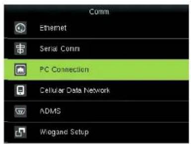
Press ▼ to select PC Connection and press OK.
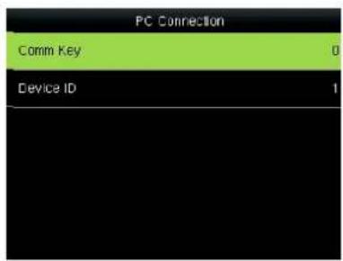
Press OK.
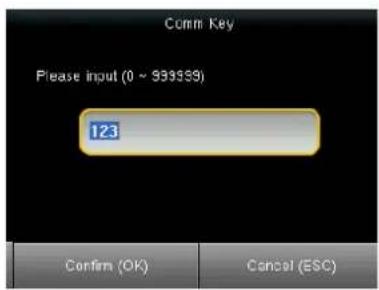
Enter a password, press to select Confirm(OK) and press OK.
5.4 Cellular Data Network★
When the equipment is in the Dial-Up Network, make sure the device is in the coverage of GPRS or WCDMA signal, and it is must known of the used modem type, APN name and access number and so on.
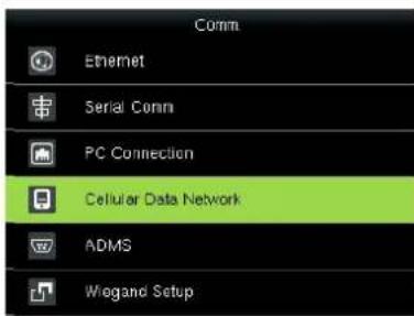
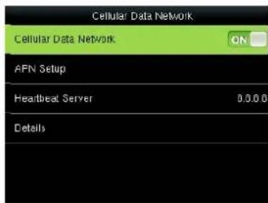
Cellular Data Network: whether to enable access to a mobile network
APN Setup: used to set APN information, such as the access number, user name, and password
Heartbeat Server: collects attendance records from the device by using the data collection software provided by ZKTeco. After you set the server IP address for the device correctly, the device will send attendance records to the heartbeat server automatically.
Details: includes information about the connected mobile network, such as the network mode, telecom operator, IP address, and received and sent data.
APN Setup:
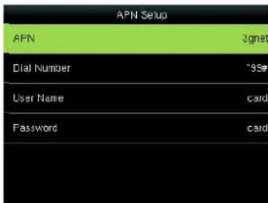
APN: Access Point Name, used to identify GPRS /WCDMA types of business.
Dial Number: The access number of GPRS /WCDMA business.
User Name and Password: used to check whether a user has the rights to access a network
5.5 Wireless Network★
Wireless Fidelity (Wi-Fi) is also known as the 802.11b standard. The greatest advantage of WIFI is its high transmission rate up to 11Mbps. Wi-Fi also features long transmission distance and excellent compatibility with various existing 802.11 DSSS devices. IEEE 802.11b is a radio-based variant of IEEE 802.11. The bandwidth of IEEE 802.11b can be up to 11 Mbps and automatically adjusted to 5.5Mbps, 2Mbps and 1Mbps depending the signal strength and interference level, thus effectively ensuring network stability and reliability. Major advantages: High transfer speed and reliability. The communication distance can be up to 305 m in an open area and 76 m to 122 m in an enclosed area. WIFI can be conveniently integrated with the existing wireline Ethernet, making the networking cost even lower.
Our terminal is also Wi-Fi capable. It supports either built-in or external Wi-Fi module to implement wireless data transmission over the Wi-Fi.
WIFI: Press OK to open or close Wi-Fi.
Operation
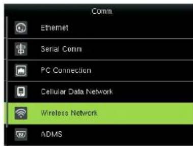
Press ▼ to select Wireless Network and press OK.
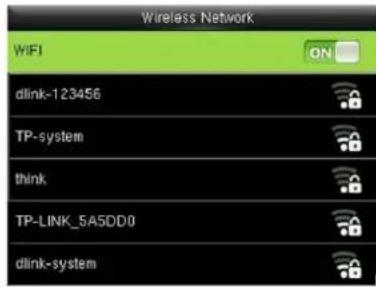
Press WIFI can open or close the function.
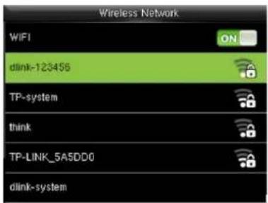
Press ▼ to select "dlink-123456" and press OK.
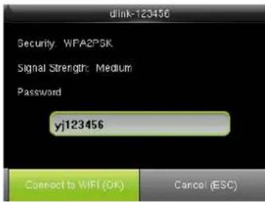
Enter a password, press ▼ to press OK.
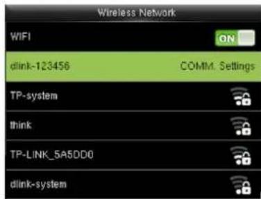
Connected, as shown in the figure
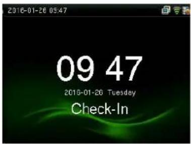
Connected, the initial interfaces shown in the figure
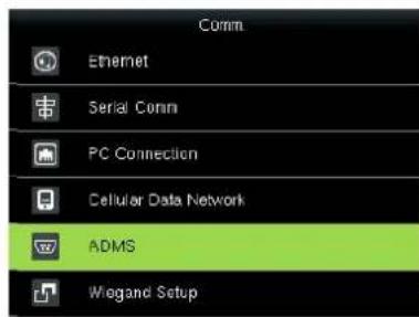
5.6 ADMS★
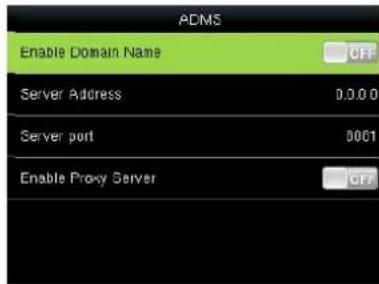
This submenu is used to connect the Webserver-related settings, such as Webserver IP address, port settings, and whether to enable proxy settings.
Enable Domain Name: When the domain name mode is enabled, you access a website using a domain name in the format of http://; otherwise, you must enter an IP address for website access.
Server Address: IP address of Webserver
Server port: Port used by Webserver
Enable Proxy Server: When you enable the proxy function, set the IP address and port number of the proxy server. This option indicates whether to use a proxy IP address. You may choose to enter the proxy IP address or the server address for Internet access, whichever you like.
5.7 Wiegand Setup
5.7.1 Wiegand INput
Operation:
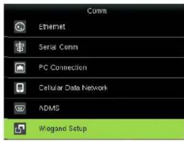
Press ▼ to select Wiegand Setup and press OK.
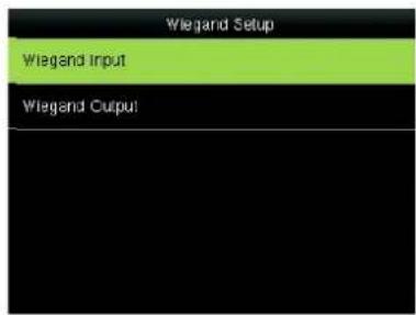
Press OK.
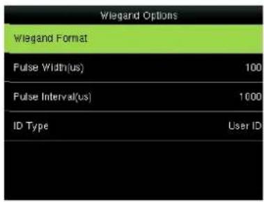
Press ▲/▼ and OK to select items. When the setting is completed, press OK to save the setting and exit.
Wiegand Format:: The system has two built-in formats Wiegand 26-bits and Wiegand 34-bits.
Wiegand Bits: specifies the number of bits occupied by the wiegand data.
Pulse width: Pulse width is 100 microseconds by default, which can be adjusted from 20 to 100.
Pulse interval: It is 1000 microseconds by default, which can adjusted between 200 and 20000.
ID Type: specifies the content of the wiegand input signal, which can be an employee ID or a card ID based on your requirement.
5.7.2 Wiegand OUTput
Wiegand Format: The system has two built-in formats Wiegand 26-bits and Wiegand 34-bits.
Failed ID: defines the output value for user authentication failures. The output format is determined by the setting of Wiegand format. The value ranges from 0 to 65535.
Site code: Similar to device ID. But the code is specified by user. Different device can be repeated. (With range of 0-255)
pulse width: Pulse width is 100 microseconds by default, which can be adjusted from 20 to 100.
Pulse interval: It is 1000 microseconds by default, which can adjusted between 200 and 20000.
ID Type: specifies the output content for successful user authentication. You can select the employee ID or card ID.
Format Details: displays the information defined by various bits of the selected wiegand format.
Operation:
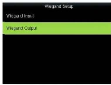
Press OK.
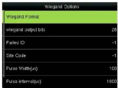
Press ▲/▼ and OK to select items. When the setting is completed, press OK to save the setting and exit.
6 System
Set system parameters to meet user's demand as many as possible. Including the Date Time, Attendance, Fingerprint and so on.
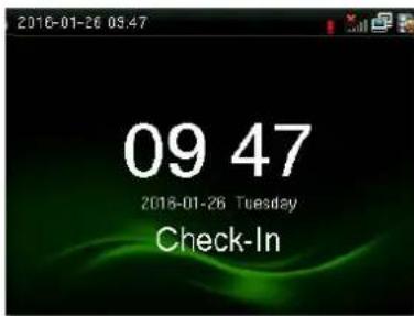
Press M/OK on the initial interface.
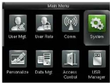
Select system and press OK.
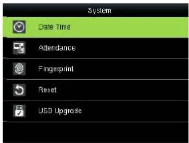
Select Date Time and press OK.
6.1 Date/Time
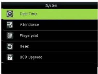
Select Date/Time and press OK.
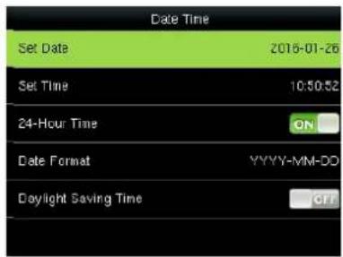
Press ▲/▼ and OK to select items. When the setting is completed, press OK to save the setting and exit.
Set Date/Time: This parameter is used to set the date and time of the FFR terminal.
24-Hour Time: This parameter is used to set the time display mode of the initial interface. Select "ON" to adopt the 24-hour display mode. Select "OFF" to adopt the 12-hour display mode.
Date Format: This parameter is used to set the format of the date displayed on the all interface of the FFR terminal.
Calendar Type: The device support the three calendar type, like Gregorian, Iran Gregorian and Iran Lunai. You can modify it if it is necessary.
Daylight Saving Time: DST, also called Daylight Saving Time is a system to prescribe local time in order to save energy. The unified time adopted during the system date is called "DST". Usually, the time will be one hour forward in summer. It can make people sleep early and get up early. It can also reduce lighting to save power. In autumn, the time will be recovered. The regulations are different in different countries.
At present, nearly 110 countries adopt DST.
To meet the demand of DST, a special option can be customized on our RF Card Time & Attendance recorder. Make the time one hour forward at XX (minute) XX (hour) XX (day) XX (month), and make the time one hour backward at XX (minute) XX (hour) XX (day) XX (month) if necessary.
Operation:
1) Set DST as "enable".
2) Input DST start time and end time.
For example, if 08:00, April 1^st is set, the device enter DST, and the time will be one hour forward. If it is 08:00, August 1^st , the device will reset normal time.
3) Press OK to save setting. Press "ESC" to exit without saving.
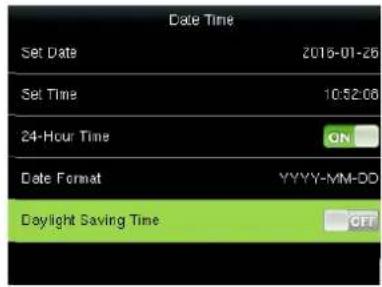
Open Daylight Saving Time
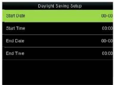
Set time in By date/time
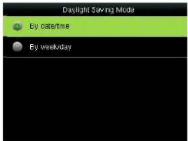
Set time in By week/day
Daylight Saving Mode: You can select the date mode (month-day-hour) or week mode (month-weekday-hour). By default, the date mode is used.
Daylight Saving Setup: used to set the DST start time and end time.
Description of the date mode and week mode:
- If the month when DST starts is later than that when DST ends, DST spans two different years. For example, the DST start time is 2012-9-1 4:00 and the DST end time is 2013-4-1 4:00.
- Assume that the week mode is selected and the DST starts from Sunday of the sixth week of September in 2012. According to the calendar, September of 2013 does not have six weeks but has five weeks. In this case, in 2013, DST starts at the corresponding time point of the last Sunday of September.
- Assume that the DST starts from Monday of the first week of September in 2012. According to the calendar, the first week of September in 2012 does not have Monday. In this case, the DST starts from the first Monday of September in 2012.
6.2 Attendance
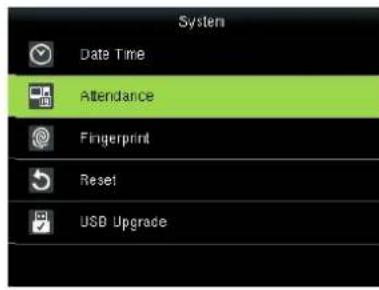
Press ▼ to select Attendance and press OK.
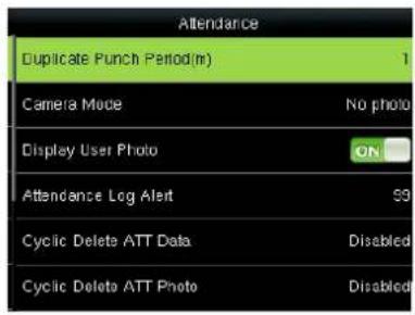
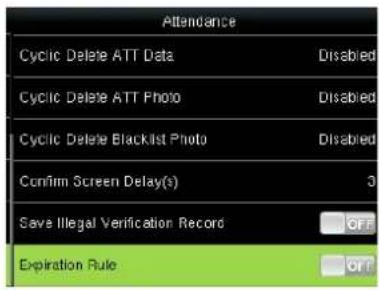
Press / and OK to select items. When the setting is completed, press OK to save the setting and exit.
Duplicate Punch Period (m): If a user's attendance record already exists and the user punches in again within the specified period (unit: minute), his/her second attendance record will not be stored. (Value scope: 1—60 minutes)
Camera Mode: when the employee is in attendance record, grasp photo and save it? It is aimed at the setting of all employees.
There are 5 modes:
No photo: there is no photo taken during attendance record.
Take photo, no save: take photo but not save photo during attendance record.
Take photo and save: take photo and save photo during attendance record.
Save on successful verification: When an employee passes the work attendance check, a picture of the employee is taken and saved.
Save on failed verification: When an employee fails the work attendance check for three times consecutively, a picture of the employee is taken and saved.
Display User Photo: whether the picture of a user is displayed when the user passes the work attendance check
Alphanumeric User ID: whether employee IDs can contain letters. Employee IDs with letters help classify employees.
Attendance Log Alert: When the available space is insufficient to store the specified number of attendance records, the FFR terminal will automatically generate an alarm. (Value scope: 1—99)
Cyclic Delete ATT Data: specifies the maximum number of attendance records that can be deleted at a time when the number of attendance records reaches the upper limit. This function can be disabled; otherwise, the value ranges from 1 to 999.
Cyclic Delete ATT Photo: specifies the maximum number of attendance pictures that can be deleted at one time when the number of attendance pictures reaches the upper limit. This function can be
disabled; otherwise, the value ranges from 1 to 99.
Confirm Screen Delay(s): specifies the time for displaying the authentication result. The value ranges from 1s to 9s.
Save Illegal Verification Record: Save the Illegal Verification Record generated in Illegal Time Zone and Illegal Combination or not when the Access Control was Enable.
Expiration Rule: You can select one of the three conditions: retaining user information and not saving attendance records; retaining user information and saving attendance records; deleting user information.
6.3 Fingerprint
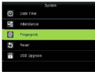
Press ▼ to select Fingerprint and press OK.
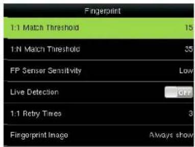
Press / and OK to select items. When the setting is completed, press OK to save the setting and exit.
1:1 matching threshold value: The similarity of ID + fingerprint verification and the enrolled template
1:N matching threshold value: The similarity of verification and the enrolled template
Recommended matching threshold value:
| FRR FAR | Matching threshold value | ||
| 1:N | 1:1 | ||
| high | low | 45 | 25 |
| middle | middle | 35 | 15 |
| low | high | 25 | 10 |
FP Sensor Sensitivity: used to set the sensitivity of fingerprint collection. The default value Medium is recommended. You can set the sensitivity of fingerprint collection to High when the response to finger scan lags in a dry environment. When the usage environment is humid, you can set the sensitivity of fingerprint collection to Low if the fingerprint is difficult to identify.
Live Detection: Select whether to open the Live ID function. Open live ID function, that is open the
fingerprint anti false function. After opening, when registering or verifying fingerprints the device would identified the false fingerprint, leading the registration failed or verified not be passed.
1:1 Retry Times: This parameter is used to set the retry times in the event of failure of 1:1 verification or password verification due to absence of fingerprint enrollment or improper finger placement, so as to avoid repetitive operations.
Fingerprint Algorithm: This parameter is used to select the fingerprint algorithm version between 9.0 and 10.0. Please select the algorithm version with caution because the fingerprint templates of these two algorithm versions are incompatible.
Fingerprint Image: This parameter is used to set whether to display the fingerprint image on the screen during fingerprint enrollment or comparison. It has two values: Permanent Display and No Display.
6.4 Reset
Make device's communication option, system option and so on reset to the state of factory.
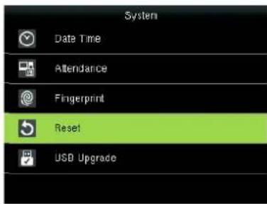
Press ▼ to select Reset and press OK.
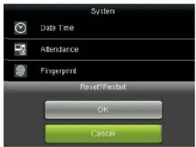
Press / to select OK or Cancel and press OK.
6.5 USB Upgrade
You can upgrade the firmware program of the FFR terminal by using the upgrade file in the USB disk through this parameter.
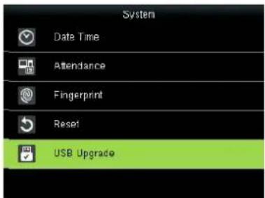
If you need the firmware upgrade file, please contact our technical support personnel. Generally the firmware upgrade is not recommended.
7 Personalize
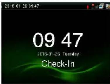
Press M/OK key on the initial interface.
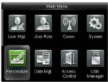
Select Personalize and press OK.
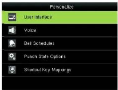
Select User Interface and press OK.
7.1 User Interface
According to their personal preferences, users can set up the initial interface style.
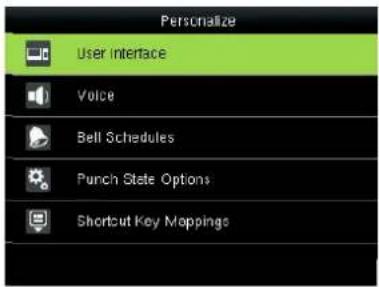
Press ▼ to select User Interface and press OK.
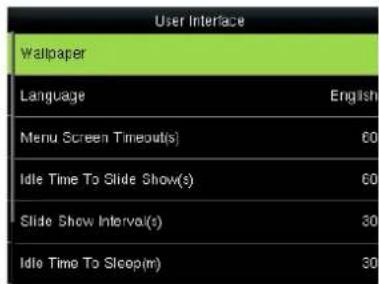
Press / and OK to select items. When the setting is completed, press OK to save the setting and exit.
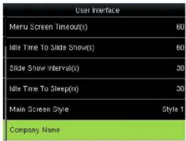
Wallpaper: Users can choose wallpaper to display on the screen.
Language: You can select a language for the device based on your requirements.
Lock power Key: To prevent hostile power-off, select whether to lock power-off or not. "disable": the power is off 3 seconds after pressing power-off. "enable": it is ineffective after pressing power-off.
Menu Screen Timeout(s): The device will display the main interface automatically when no operation is performed on a menu within the menu timeout time. (This function can be disabled; otherwise, the value ranges from 60s to 99999s.)
Idle Time To Slide Show(s): The advertisement picture is displayed when no operation is performed on the main interface within the waiting time. (This function can be disabled; otherwise, the value ranges from 3s to 999s.)
Slide Show Interval(s): This parameter is used to set the picture cycle interval (value scope: 0-999 seconds).
Idle Time To Sleep(m): This parameter is used to specify a period after which the device is put in sleep
mode if no operation within this period. You can wake up the device from sleep by pressing any key or touching the screen. Numerical range in 1 \~ 30 minutes, the factory default for 3 minutes.
Main Screen Style: set where and how the clock and status key are displayed on the main screen.
Notes: Company name is only in the case of open print function can be set.
7.2 Voice
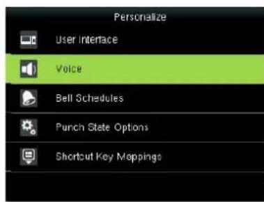
Press ▼ to select Voice and press OK.
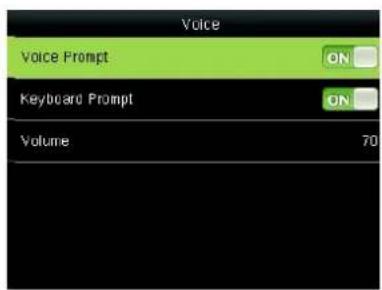
Press / and OK to select items. When the setting is completed, press OK to save the setting and exit.
Voice Prompt: This parameter is used to set whether to play voice prompts during the operation of the FFR terminal. Select "ON" to enable the voice prompt, and select "OFF" to mute.
Keyboard Prompt: This parameter is used to set whether to generate beep sound in response to every keyboard touch. Select "ON" to enable the beep sound, and select "OFF" to mute.
Volume: This parameter is used to adjust the volume of voice prompts.
7.3 Bell Schedules
Many companies need bell for on-duty and off-duty. Some use manual bell. Some use electronic bell. To save cost and provide convenience for management, we integrate bell functions to fingerprint sensor. You can set time for bell. When it is the scheduled time, The device will automatically play the selected ringtone and trigger the relay signal. The ringtone playing does not stop until the ringing duration has elapsed. By default, the device provides 15 ringtones.
1. Adding a Bell
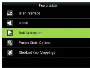
Press ▼ to select Bell Schedules
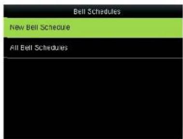
Press ▼ to select New Bell
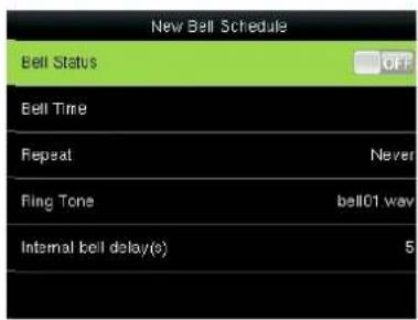
Press▲ /▼ and OK to select items,
and press OK.
Schedules and press OK.
press OK to save and exit.
Bell Status: Whether to enable this bell
Bell Time: The bell rings automatically when it is the specified time.
Repeat: specifies whether to repeat the ringtone.
Bell Type: You can select between internal ringing and external ringing. For internal ringing, the ring tone is played by the loudspeaker of the terminal. For external ringing, the ring tone is played by an external electric bell that is wired with the terminal.
Ring Tone: Bell ring
Internal bell delay(s): specifies the duration for ringtone playing. The value ranges from 1s to 999s.
Notice: Only some models have external ringing★ options.
2. Edit and delete a Bell
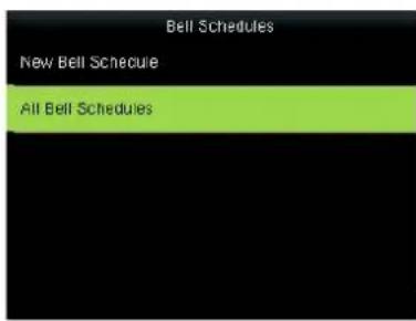
Press ▼ to select Bell Schedules and press OK.
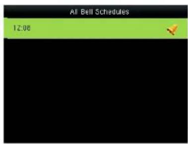
Select New Bell Schedules and press OK.
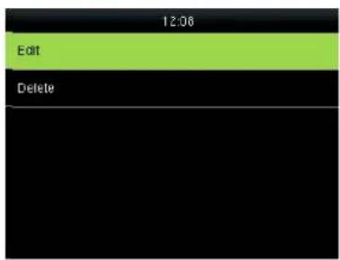
Select Edit and press OK.
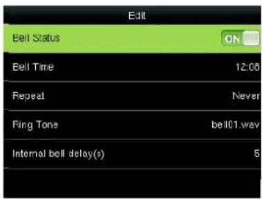
Select Item.
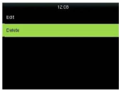
Press ▼ to Delete and press OK.

Press ▼ to select "Yes" or "No".
3. Options
When the function of external ringing★ is used, set the output terminal of external ringing★.
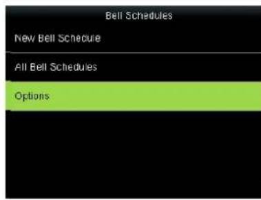
Press ▼ to select Options and press OK.
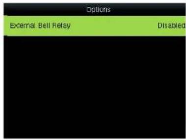
Press OK.
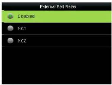
Press ▼ to select, press OK to save and return.
7.4 Punch State Options
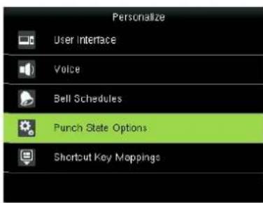
Press ▼ to select Punch State Options and press OK.
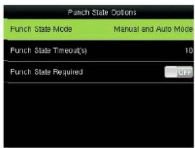
Press ▲/▼ and OK to select items. When the setting is completed, press OK to save the setting and exit.
Punch State Mode: used to select a status key mode. The following modes are available:
Off: The status key function is not used. The status keys defined as shortcut keys become unavailable.
Manual Mode: The status keys are switched manually and the current status key will disappear when the preset time elapses.
Auto Mode: If a shortcut status key is configured to be switched after a period of time, the status key is switched automatically when the period of time elapses.
Manual and Auto Mode: The main interface displays the status keys that can be switched automatically, and you are also allowed to switch status keys manually. A status key you select manually will be switched according to the automatic switching plan after it disappears upon a timeout.
Manual Fixed Mode: After a status key is switched, it is always displayed until you switch it later again.
Fixed Mode: A status key is always displayed and cannot be switched.
Punch State Timeout(s): specifies the timeout period of the status key displayed on the main interface.
Punch State Required: specifies whether the status of work attendance check must be selected during authentication.
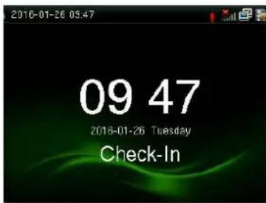
You can define six shortcut keys as attendance status shortcut keys or functional shortcut keys. On the main interface of the FFR terminal, press corresponding keys and the attendance status will be displayed or the function interface will be rapidly displayed.
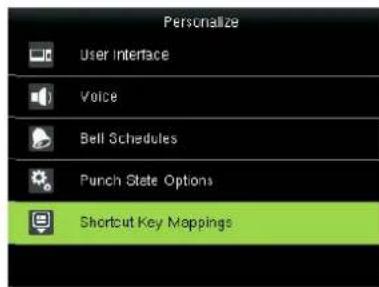
Press ▼ to select Shortcut Key Mappings and press OK.
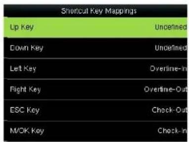
Press to select a key and press OK.
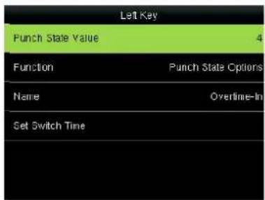
Press / and OK to select items. When the setting is completed, press OK to save the setting and exit.
Notes: When setting the attendance status shortcut keys, you can also set the "Auto Switch" parameter. When "Auto Switch" is enabled, the FFR terminal automatically switches the attendance status at the specified time. If a status key is selected, the device will not use any status key when the status key function is disabled.
8 Data Mgt.
Press M/OK key on the initial interface.
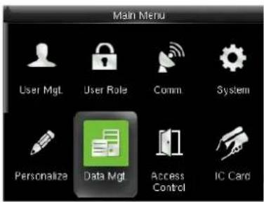
Select Data Manager and press OK.
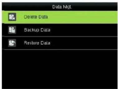
Select Delete Data and press OK.
8.1 Delete Data
Through the [Data Mgt.] menu, you can perform management of data stored on the FFR terminal, for example, deleting the attendance record, all data and promotional pictures, purging management rights and resetting the FFR terminal to factory defaults.
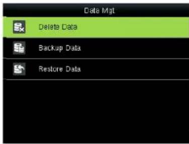
Select Delete Data and press OK.
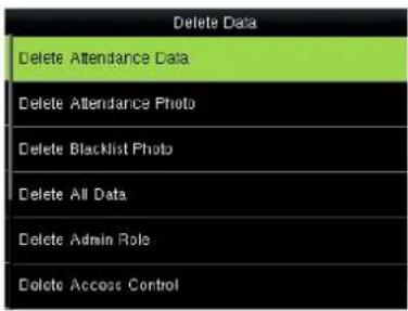
Press ▼ and OK to select the item to be deleted.
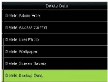
Delete Attendance Date: Delete all the attendance records.
Delete Attendance Photo: Delete all employees' attendance photos.
Delete Blacklist Photo: Delete the saved photos which fail in passing attendance record.
Delete All Data: Delete all the information of enrolled personnel, including their fingerprints, facial images and attendance records.
Clear Admin Role: Change all administrators to ordinary users.
Delete Access Control: Delete all Access Control records.
Delete User Photo: Delete all User Photo.
Delete Wallpaper: Delete all Wallpaper.
Delete Screen Savers: Purge the promotional pictures uploaded from USB disks to the FFR terminal. (For
details on how to upload promotional pictures, see "5.4 Upload Picture".
Delete Backup Date: Delete the backup data from the device.
8.2 Backup Data
Back up the service data or configuration data of the device to the device or a USB drive.
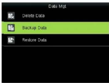
Press ▼ to select Backup Data and press OK.
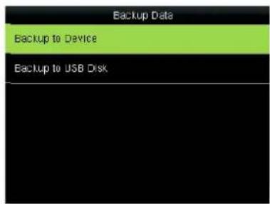
Press to select Backup to Device and press OK.
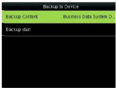
Press and OK to select the local configuration items to be backuped to decide the selected items.
![Backup to Device Backup Content Business Data System D... Backup start Backup is completed! [ESC] to exit.](/content/2026/05/949767/images/a77ac7d2c193a3c70bd09c3843ad6d27720024838b5de4db638cfa41e28ba897.jpg)
Press ▼ to select Backup start and press OK.
Note: Backup to USB Disk, the operations are similar to those performed to Backup to Device.
8.3 Restore Data
Restore the data stored on the device or in the USB drive to the device.
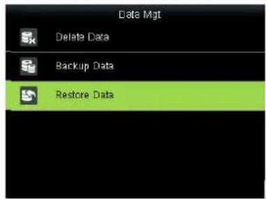
Press ▼ to▼ select Restore Data and press OK.
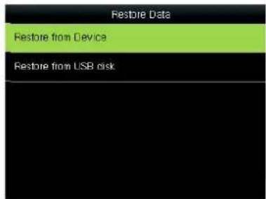
Press to select Backup from Device and press OK.
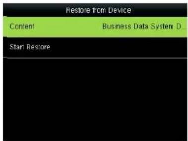
Press and OK to select the local configuration items to be restored and save the selected items.
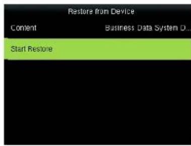
Press ▼ to select Start Restore and press OK.
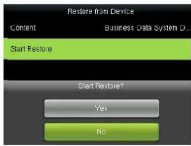
Press ▼ to select "Yes" or "No" Device and press OK.
Note: Backup from USB Disk, the operations are similar to those performed to Backup from Device.
9 Access Control Setting
Access control option is to set user's open door time zone, control lock and related device's parameters.
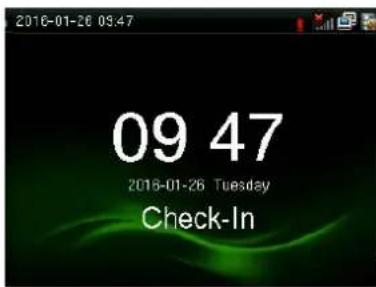
Press M/OK on the initial interface.
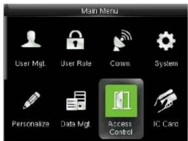
Press▶to select Access control and press OK.
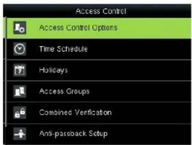
Press ▼ to select Access Control Options and press OK.
To unlock, the enrolled user must accord with the following conditions:
- The current unlock time should be in the effective time of user time zone or group zone.
- The group where user is must be in access control (or in the same access control with other group, to open the door together).
The system default the new enrolled user as the first group, default group time zone as 1, access control as the first group, and the new enrolled user is in unlock (if user has modified the related setting of access control, the system will be changed with user's modification.)
9.1 Access Control Options
Set parameters to control locks and related device.
Door Lock Delay(s): Device control electronic lock is in enabling time. (effective value 1 10 seconds
Door Sensor Delay(s): After the door is open, delay the time to check door sensor. If door sensor state is different from the normal state of door sensor mode, alarm will be given off. This time is called door sensor delay. (effective value: 1 99 seconds
Door Sensor Type: It includes NONE, NC and NO. NONE means there is no door sensor. NO means the door is open normally. NC means the door is closed normally.
Door Alarm Delay(s): When abnormal door sensor state is detected, alarm will be given off after some time. This time is door sensor alarm. (effective value: 1–99 seconds
Retry Time To Alarm: When the failed press times reach the set times, alarm signal will come out.
(effective value 1 9 times
NC Time Period: Set time zone for access control NC. Nobody can unlock during this time zone.
NO Time Period: Set time zone for access control NO. The lock is always in enabling state during this time zone.
Operation
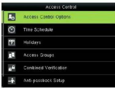
Select Access Control Options and press OK.
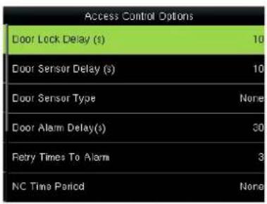
Enter to Access Control Options, As shown in the figure.
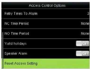
Press ▲/▼ to move cursor to the item to be set. If it is the input box, press numeric keys on small keyboard to input the value. If it is the roll box, press ◀/▶ to switch the values. After setting, press menu directly to return to the last interface. Press "ESC" to cancel setting and return to the last interface.
Notice
1) When time zone is set for NO or NC, please set door sensor mode as None, or alarm signal may come out during time zone of NO or NC.
2) If time zone of NO or NC has no definition, the device will prompt it and add the definition in time zone setting.
9.2 Time Schedule
Time zone is the minimum unit of access control option. The whole system can define 50 time zones. Every time zone defines seven time sections (namely, a week). Every time section is the effective time zone within 24 hours everyday. Every user can set 3 time zones. "or" exists among the three zones. It is effective if only one is satisfied. Every time section format is HH:MM-HH:MM, namely, accurate to minute.
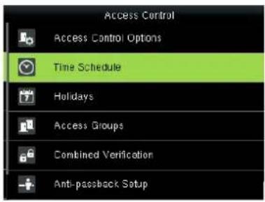
Press ▼ to select Time Schedule and press OK.
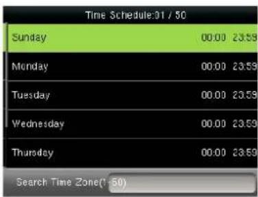
Use numeric keys to search for a time period in the range from 1 to 50. Press ▼ to select the item to be set and press OK.
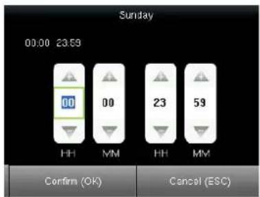
Press ◀/▶ to select a time option and press ▲/▼ to set time. After setting a period of time, press OK to save the setting and exit.
If end time is smaller than start time (23:57- 23:56), the whole day is forbidden. If end time is bigger than start time(00:00- 23:59), it is effective section. Effective time zone for user unlocking:00:00- 23:59 or
end time is bigger than start time.
Notes: The default time period number 1 indicates all-time access (that is, newly registered users are unlocked).
9.3 Holiday setting
Special access control time may need during holiday. It is different to modify everybody's access control time. So a holiday access control time can be set, which is applicable for all employees.
After holiday access control time is set, user's open door time zone during holiday subject to the time zone here.
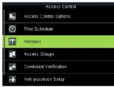
Press ▼ to select Holidays and press OK.
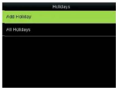
Press OK to Add Holiday.
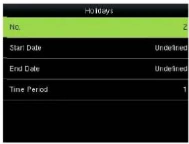
Press OK.
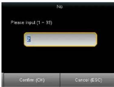
Enter the No. using keypad. Press OK.
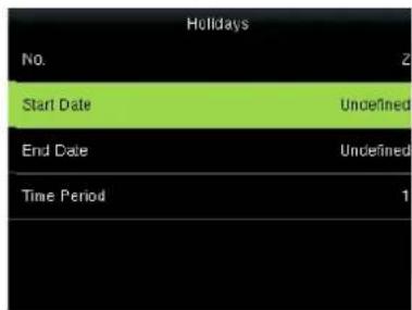
Press ▼ to select Start Date and End Date and press OK.
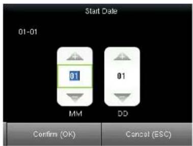
Press ◀/▶ to select a time option and press ▲/▼ to set time. After setting a period of time, press OK to save the setting and exit.
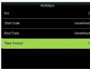
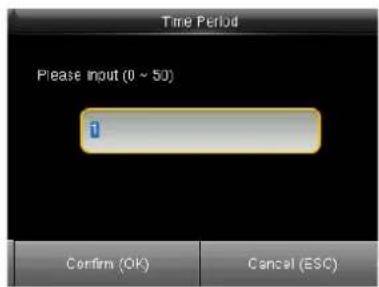
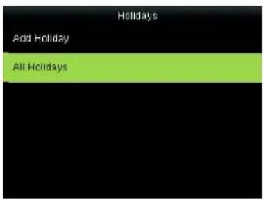
Press ▼ to select Time period and press OK.
Enter the Time period using keypad. Press OK to return.
Press ▼ to select All Holidays and press OK.
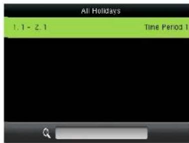
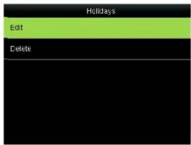
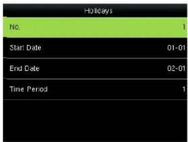
To check the effective time period of a holiday, enter numbers and you can view the duration of a holiday. Press OK.
Press OK to Edit Holidays.
Edit Holidays operations are similar to those performed to add Holidays.
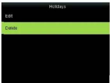
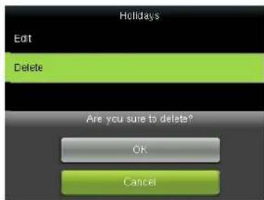
Press ▼ to select Delete and press OK.
9.4 Access Groups
Grouping is to manage employees in groups. Employee in groups use group time zone by default. Group members can also set user time zone. Every group can hold there time zones. The new enrolled user belongs to Group 1 by default. He can also be allocated to other groups.
Operation
1) Add group time zone
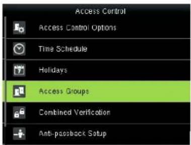
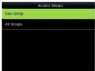
Press ▼ to select Access Groups and press OK.
Press OK to add New Group
Press OK
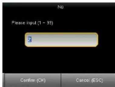
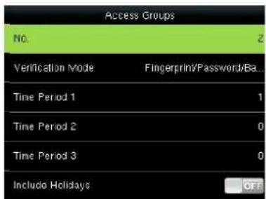
Enter the No. using keypad and press OK.
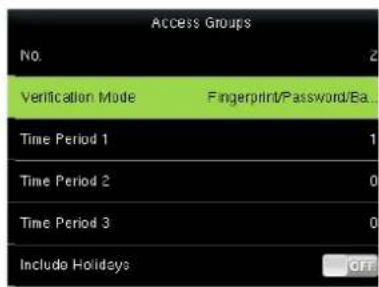
Press ▼ to select Verification Mode and press OK.
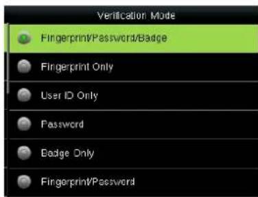
Press / to select Verification Mode, press OK to save and return.
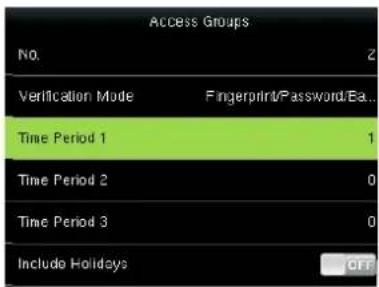
Press ▼ to select Time Period 1 and press OK.
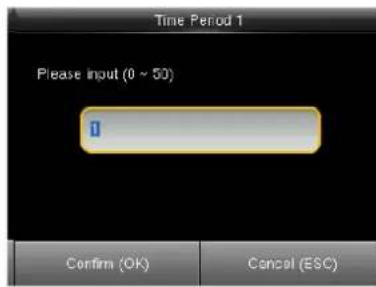
Enter the No. using keypad and press OK.
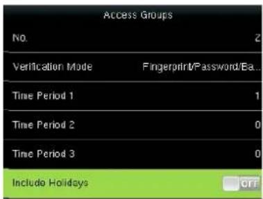
Press ▼ to select Include Holidays, press OK to enable the item.
Notice:
- If holiday is effective, only when there is intersection between group zone and holiday time zone, can the group member open the door.
- If holiday is ineffective, the access control time of group member won't be affected by holiday.
2) Edit and Delete group time zone
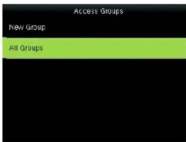
Press ▼ to select All Groups and press OK.
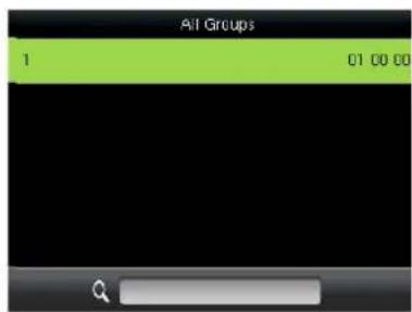
Press to select one of All Groups and press OK.
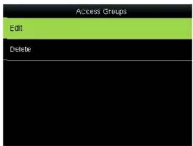
Press to select Edit and press OK.
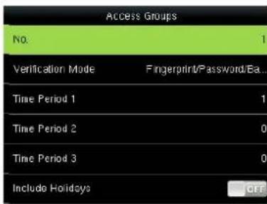
The No. cannot be modified, and the other operations are similar to those performed to add a New Groups. Press ESC to return.
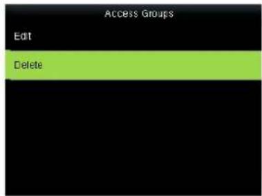
Press ▼ to▲select Delete and press OK.
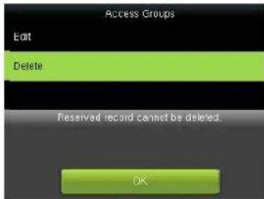
Press / to select OK to delete the Access Groups.
9.5 Set Combined Verification
Make various groups into different access controls to achieve multi-verification and improve security. An access control can be made up of 5 groups at most.
Operation
1) Add Combined Verification
For example, to add an unlocking combination which needs the verification of both group 1 and 2, as shown below:
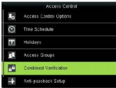
Press ▼ to select Combined Verification and press OK.
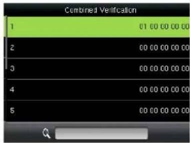
Press OK to add a new Combined Verification.
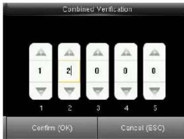
Enter the No. using keypad and press OK.
2) Edit and Delete Combined Verification
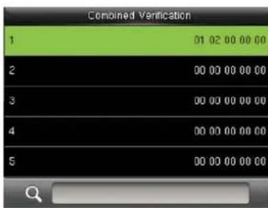
Press ▼ to select the line to be
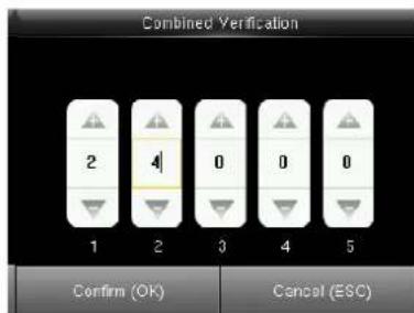
Enter the No. using keypad and
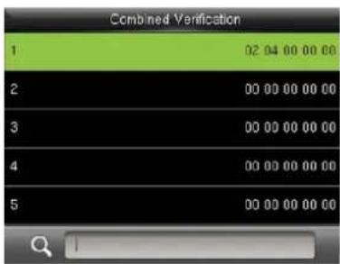
When setting successful, an
Notes: To delete an unlocking combination, set the group ID to all 0s.
9.6 Anti-pass back
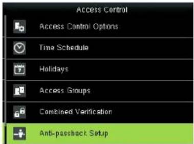
Sometimes, some illegal person follows the employee into the gate, which will bring security problem. To prevent such risk, this function is enabled. In record must match out record, or the gate won't be open. This function needs two machines to work together. Refer to Appendix 4 anti-pass back (for anti-pass back setting.
9.7 Duress alarm parameter
There is duress alarm parameter setting in the device. When employee come across duress, select duress alarm mode, the device will open the door as usual. But the alarm signal will be sent to backstage alarm.
Duress Function: If select "Yes", press help then press fingerprint in the following 3 seconds or press ID number, and duress alarm will come out after successful identification. If select "No", it is useless to press help. (help can be set in keyboard definition.)
Alarm on 1:1 Match: if select "Yes", when user use 1:1 match mode, alarm signal will come out. Or there is no alarm signal.
Alarm on 1:N Match: if select "Yes", when user use 1:N match mode, alarm signal will come out. Or there is no alarm signal.
Alarm on Password: If select "Yes", when user use password verification mode, alarm signal will come out. Or there is no alarm signal.
Alarm Delay(s): After duress alarm gets started, the alarm signal is not output directly. But it can be defined. After some time, alarm signal will be generated automatically. (0-255 seconds).
Operation:
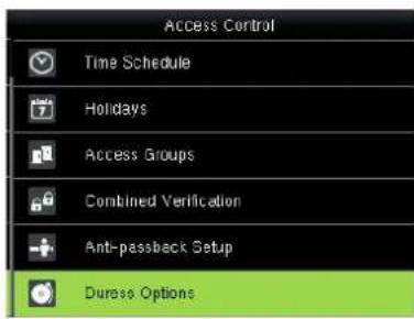
Press ▼ to select Duress Options and press OK.

Enter to Access Control Options, As shown in the figure:
Press ▲/▼ to move cursor to the item to be set. If it is the input box, press numeric keys on small keyboard to input the value. If it is the roll box, press ◀/▶ to switch the values. After setting, press menu directly to return to the last interface. Press "ESC" to cancel setting and return to the last interface..
10 USB Manager
Import user information, fingerprint template, attendance data and so on in the device to attendance software or import user information and fingerprint to other devices through U disk.
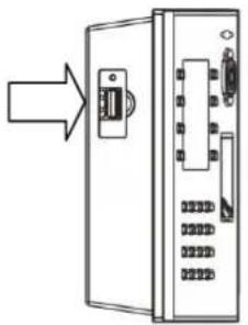
Before you upload/download data from/to a USB drive, insert the USB drive into the USB interface of the device.
natural_image
Diagram of an electronic device showing a switch and internal components (no text or symbols)Insert U disk into USB slot of fingerprint sensor through mini USB cable.
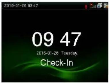
Press M/OK on the initial interface.
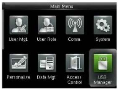
Press ▼ to Select USB Manager and press OK.
10.1 Download
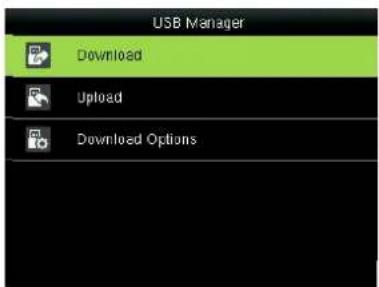
Select Download and press OK.
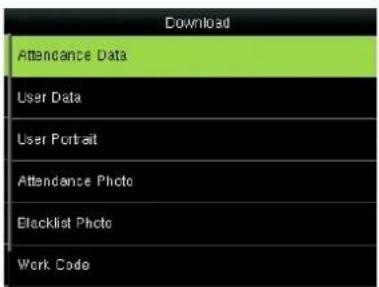
Press ▼ and OK to select the item to be downloaded.
Download Attendance Data: Import all the attendance data from the FFR terminal to a USB disk.
Download User Data: Import all the user information, fingerprints and facial images from the FFR terminal to a USB disk.
Download User Portrait: Import the employees' photos from the terminal to a USB disk.
Download Attendance Photo: Download attendance photos saved in device to U disk. The format of photo is JPG.
Download Blacklist Photo: Download black list photos saved in device to U disk. The format is JPG.
Download work code: used to save work IDs on the device to a USB drive
10.2 Upload
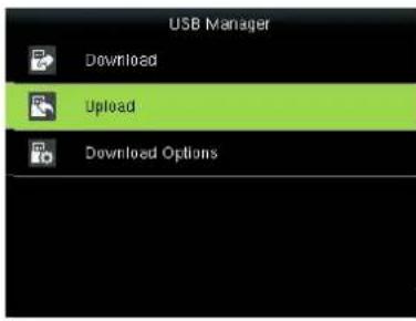
Press ▼ to Select Download and press OK.
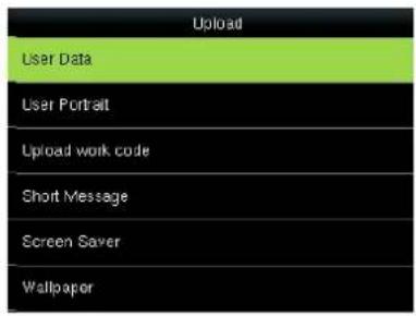
Press ▼ and OK to select the item to be Uploaded.
Upload User Data: Upload the message stored in a USB disk to the terminal.
Upload User Portrait: Upload the JPG documents that are named after the user IDs and stored in a USB disk to the terminal, so that user photos can be displayed after the employees pass the verification.
Upload work code: used to upload work IDs in a USB drive to the device.
Upload Short Message: used to upload short message in a USB drive to the device.
Upload Screen Saver: Upload the JPG documents with "ad_" as initial letters of document names stored in a USB disk to the terminal. After the upload, these pictures can be displayed on the initial interface of the terminal. (For details on picture specifications, see Appendix 2 Image Upload Rules
Upload Wallpaper: Upload the JPG documents with "1\~10.jpg" as initial letters of document names stored in a USB disk to the terminal. After the upload, these pictures can be displayed on the interface of the terminal. (For details on picture specifications, see Appendix 2 Image Upload Rules
10.3 Download Options
You can encrypt the data in a USB drive and set to delete data after being downloaded. When download the attendance records, you can also set the calendar type displayed in the attendance time. The device support hree calendar types which are Gregorian, Iran Gregorian, Iran Lunar to choose.
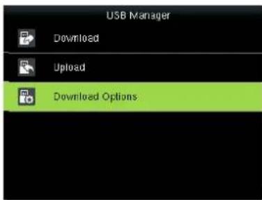
Press ▼ to Select Download Options and press OK.
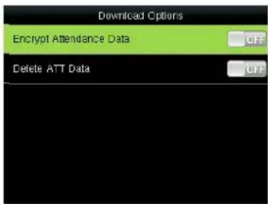
Press ▼ and OK to select items. When the setting is completed, press OK to save the setting and exit.
11 Attendance Search
Employee's attendance record will be saved in the device. For query convenience, query record function is provided.
1. Attendance Record
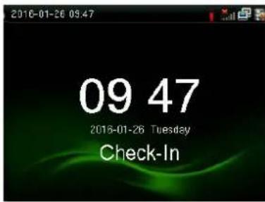
Press M/OK on the initial interface.
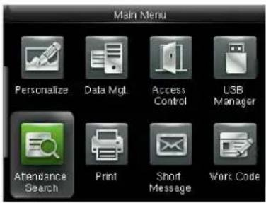
Press ▶ to select Attendance Search and press OK.
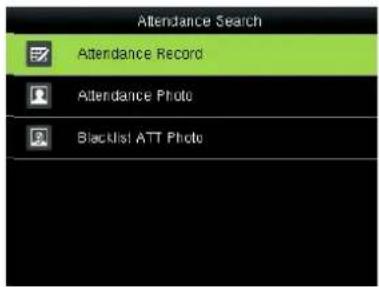
Press▶to select Attendance Record and press OK.
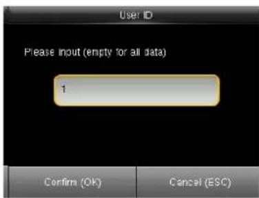
Enter the user ID then press OK.
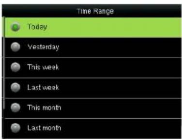
Press▶to select Time and press OK.
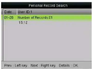
The records in accordance with the conditions will be displayed:
User ID: Enter the user ID of the employee to query. If this field is left blank, you can query the attendance records of all the employees. If you enter a user ID, you can query the attendance record of the employee with this user ID.
Time Range: Select a time period to query, including the customized time period, yesterday, this week, last week, this month, last month, and all time periods.
- Attendance Photo and Blacklist ATT Photo
The operations are similar to those performed to Attendance Record.
12 Print★
You can connect the device to a printer so that attendance records can be printed.
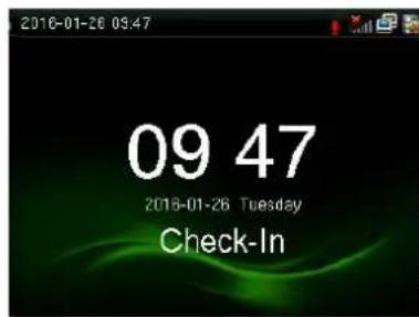
Press M/OK on the initial interface.
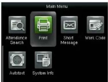
Press▶to select Print, press OK.
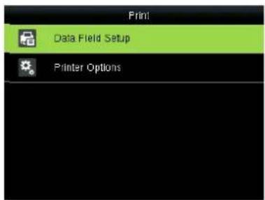
Press ▼ to select Data Field Setup and press OK.
12.1 Data Field Setup
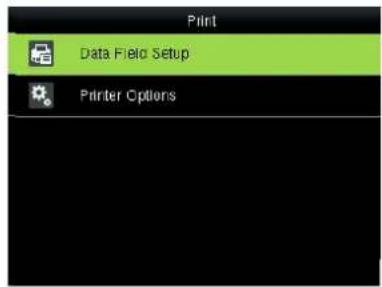
Press ▶to select Data Field Setup and press OK.
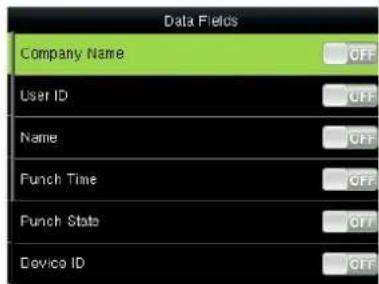
Press ▶ to select the item to be set and press OK to enable or disable the selected item.
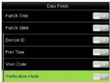
12.2 Printer Options
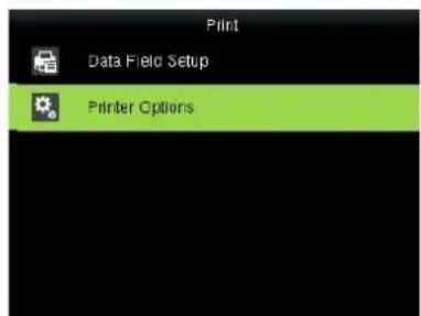
Press ▶to select Printer Options and press OK.
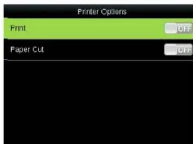
Press ▶ to select the item to be set and press OK to enable or disable the selected item.
Notes: To enable the paper cutting function, connect the device to a printer equipped with the function. Paper cutting is implemented automatically during printing based on the selected print information
13 Short Message
SMS is similar to notice. The operator can edit the notice content in advance and make it into SMS displayed on the screen. SMS includes common SMS and individual SMS. If common SMS is set, will be displayed in information column at the top of standby interface in the specified time. If individual SMS is set, the employee who can receive SMS can see SMS after successful attendance.
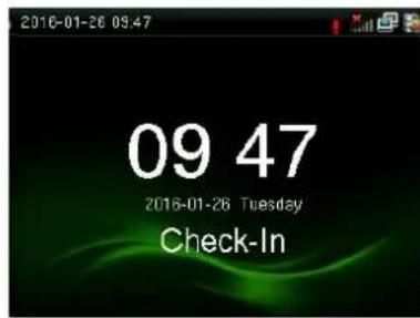
Press M/OK on the initial interface.
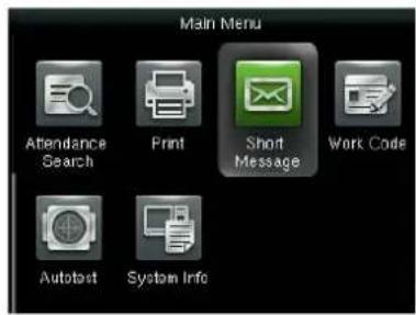
Press ▶to select Short Message and press OK.
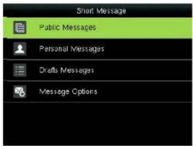
Select New Message, press OK.
You should get the short message from the computer at first.
13.1 Public, Personal and Drafts lists
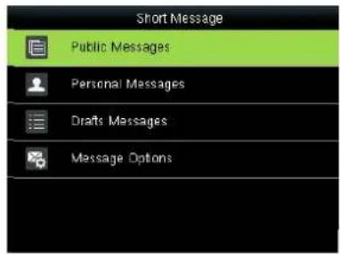
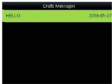
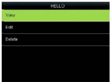
Press ▼ to select the message list then press OK. You can view, edit or delete the one you selected. When edit message, the operations are similar to those performed to add a SMS.
13.2 Message Options
Set the personal Message Show Delay time on the initial interface.
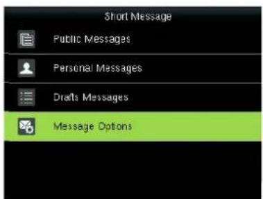
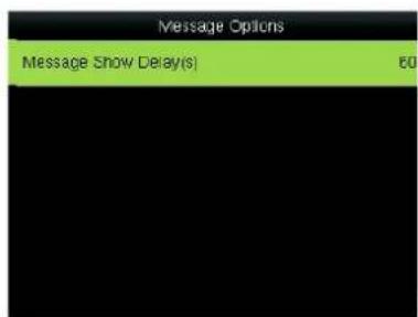
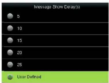
Press ▶to select Message Options and press OK.
Press OK.
Press▼ to select the time and press OK
13.3 Employee check SMS
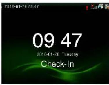
After configuration of a public short message, within the specified time period, the main interface displays the short message icon in the upper right corner and displays the content of public short messages in scrolling mode in the lower part so that all employees can view the information. The content of private short messages for a user is displayed when the user is authenticated.
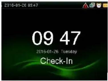
Public message
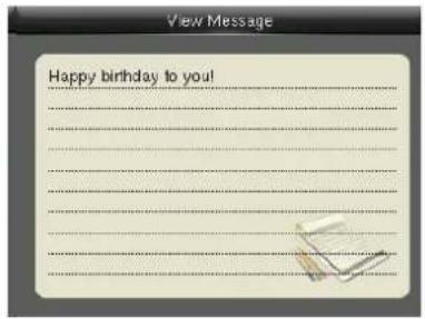
ser authentication is successful after the show users messages.
14 Work Code
Employees' salaries are subject to their attendance records. Employees may be engaged in different types of work which may vary with time periods. Considering the salaries vary with work types, the FFR terminal provides a parameter to indicate the corresponding work type for every attendance record to facilitate rapid understanding of different attendance situations during the handling of attendance data.
Press M/OK on the initial interface.
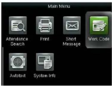
Press ▶to select Work Code and press OK.
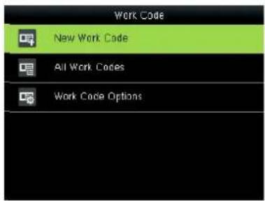
Press▼ to select New Work Code and press OK.
14.1 Add a work code
ID: A digital code of the work code.
Name: The meaning of the work code.
- Enter the ID.
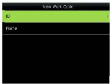
Select ID and Press OK.
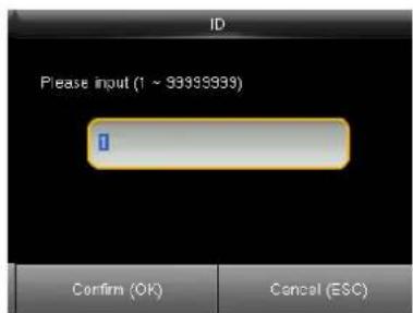
Enter the user ID using keypad, press OK.
Tip: The terminal supports the 1-to 99999999-digit IDs by default. If a prompt message "The ID already exists!" is displayed, enter another ID.
2 Enter the name
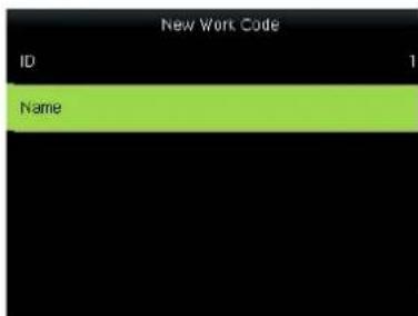
Select Name and press OK.
![Name Please input fig[1]re] Right key to switch input method, Left key to back space [a]](/content/2026/05/949767/images/effe635c8bce4baaf30b53e40859acae1ced30c1adb411e7305452a1766c9ee4.jpg)
Enter the name then press OK.
The terminal supports the 1- to 23-character names by default. For details of enter name, see Appendix1 Text Input Instructions.
14.2 All Work Codes
You can view, edit or delete the work code from the work codes list. The ID cannot be modified, and the other operations are similar to those performed to add a work code When edit.
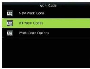
Press ▶to select All Work Codes and press OK.
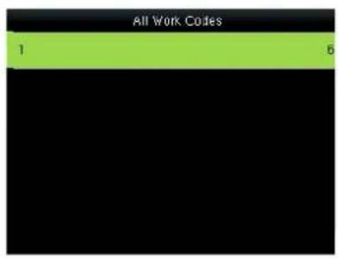
View all work codes.
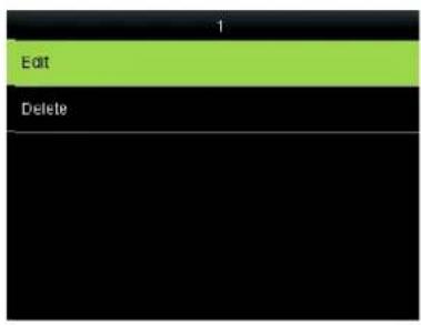
Press▼ to select the one you want to edit or delete.
14.3 work code Options
Set verify whether enter the Work Code number must be entered must exist.
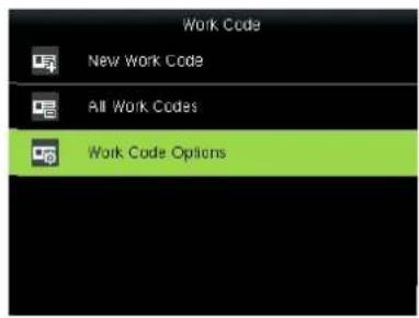
Press ▶to select Work Code Options and press OK.
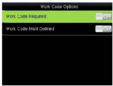
Press OK to open or close.
15 AutoTest
The auto test enables the system to automatically test whether functions of various modules are normal, including the LCD, voice, sensor, keyboard and clock tests.
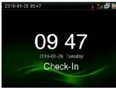
Press M/OK on the initial interface.
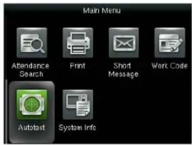
Press ▶to select Diagnostics and press OK.

Press▼ to select the one you want to see and press OK.
Test All: The terminal automatically tests the LCD, voice, sensor, keyboard and clock, press [OK] to continue and press [ESC] to exit.
Test LCD: The terminal automatically tests the display effect of the color TFT display by displaying full color, pure white and pure black and checks whether the screen displays properly. You can continue the test by touching the screen or exit it by pressing [ESC].
Test Voice: The terminal automatically tests whether the voice files are complete and the voice quality is good by playing the voice files stored in the terminal. You can continue the test by touching the screen or exit it by pressing [ESC].
Test Keyboard: The terminal tests whether every key on the keyboard works normally. Press any key on the [Keyboard Test] interface to check whether the pressed key matches the key displayed on screen. The keys are dark-gray before pressed, and turn blue after pressed. Press [ESC] to exit the test.
Test Fingerprint Sensor: The terminal automatically tests whether the fingerprint collector works properly by checking whether the fingerprint images are clear and acceptable. When the user places his/her finger in the fingered guide, the collected fingerprint image is displayed on the screen in real-time. Press [ESC] to exit the test.
Cam testing: The device automatically tests whether the camera works properly by checking whether the collected images are clear and acceptable. Press [ESC] to exit the test.
Test Clock RTC: The terminal tests whether its clock works properly by checking the stopwatch of the clock. Touch the screen to start counting, and touch it again to stop to check whether the counting is accurate. Press [ESC] to exit the test.
16 System Information
You can check the storage status as well as firmware information of the terminal through the [System Information] option.
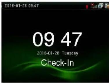
Press M/OK on the initial interface.
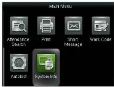
Press ▶to select System Info and press OK.
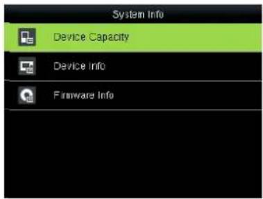
Press▼ to select the one you want to see and press OK.
Device Capacity: The number of enrolled users, administrators, passwords, the total fingerprint storage capacity and occupied capacity, ID cards and attendance capacity are displayed respectively.
Device info: The Device name, serial number, MAC Address, Fingerprint Algorithm, Manufacture and Manufacture date are displayed on the device interface.
Firmware info: The Firmware version, Bio Service, Push Service, Standalone Service and Dev Service are displayed on the firmware info interface.
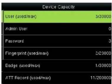
Device Capacity
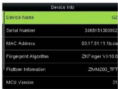
Device information
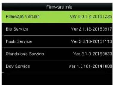
Firmware information
Appendix
Appendix 1 Description of Text Input Operation
The device can recognize English letters, symbols, and numbers. Press * to display the input method and press * again to switch the input method. Press # to enter a space. Press ESC to exit the input method.
Description of entry of English letters and symbols (for example, creating a short message)
![Message [Aa]](/content/2026/05/949767/images/08a8257f3121c2fc80587da40da76e9a8c7750ca089a3d963c5858e3481219c3.jpg)
Press * to display the input method.
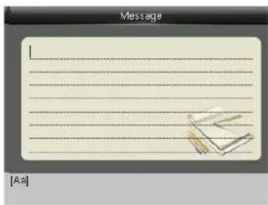
Press * again to switch the input method. Select Aa, a, or A for using uppercase and lowercase letters based on requirements.
![Message [As] G H I](/content/2026/05/949767/images/6bfa0ac4b8af8e5671d04b6f9b731e8327c38ffba8ceb076d17d2a4d10978e2e.jpg)
If necessary, you can press 4 twice in succession to select H.
![Message H [Aa] a b c](/content/2026/05/949767/images/06117a3edce041b6e4523b2d6e6f99b666f9630d01d4755b4344922d953679df.jpg)
Press 2 to select a. Finish the text input in the same way.
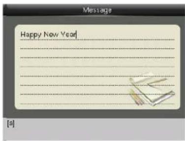
Press # to enter a space if necessary.
![Message Happy New Year [symbol] 0, 1, 2, 3, 4/5?6!7%8@>](/content/2026/05/949767/images/ee5c3aab1f7e7ddc4d631874946cb2f863d070f1fdef13c872a2d33468c815e5.jpg)
Press * to switch to the symbol input method and press 6. Select !. When you complete the input, press ESC to exit.
Appendix 2 Image Upload Rules
User photo: Create a new directory named "photo" in the root directory of disk U and place user photos into the directory. A maximum of 8,000 photos can be stored and the size of each photo cannot exceed 15 KB. The image name is X.jpg (X is the user's employee ID, which is not limited in the number of digits). Images must be in .jpg format.
Advertising image: Create a new directory named "advertise" in the root directory of disk U and place advertising images into the directory. A maximum of 20 images can be stored and the size of each image
cannot exceed 30 KB. There are no restrictions on the image name and type.
Wallpaper: Create a new directory named "wallpaper" in the root directory of disk U and place wallpapers into the directory. A maximum of 20 wallpapers can be stored and the size of each wall paper cannot exceed 30 KB. There are no restrictions on the image name and type.
Note: If the size of a single user photo or attendance photo is 10 KB or less, a total of 10,000 photos can be stored.
Appendix 3 anti-pass back
【overview】
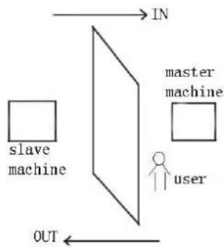
Sometimes, some illegal person follows the employee into the gate, which will bring security problem. To prevent such risk, this function is enabled. In record must match out record, or the gate won't be open.
This function needs two machines to work together. One is installed inside the door (master machine hereinafter), the other is installed outside the door (slave machine hereinafter). Wigand signal communication is adopted between the two machines.
flowchart
graph TD
    A["slave machine"] --> B["master machine"]
    B --> C["user"]
    D["IN"] --> B
    E["OUT"] --> B
【working principle】
The master machine has Wigand In and slave machine has Wigand Out. Connect Wigand Out of slave machine to Wigand In of master machine. Wigand output from slave machine must not own machine ID. The number sent to master machine from slave machine must be found in the master machine.
【function】
Judge whether it is anti-pass back according to user's recent in-out record. In record and out record must be matched. This machine supports out, in, or out-in anti-pass back (enter machine menu—setting—system setting—advanced setting—anti-pass back).
When master machine is set as "out anti-pass back", if user wants to come in and go out normally, his recent record must be "in", or he cannot go out. Any "out" record will be "anti-pass back refused". For example, a user's recent record is "in", his second record can be "out" or "in". His third record is based on his second record. Out record and in record must match. (if customer has no record before, then he can come in but cannot go out.)
When the master machine is set as "in anti-pass back", if the user wants to come in and go out normally, his recent record must be "out", or he cannot go out. Any out record will be "anti-pass back refused" by the system.
(Notice: if the customer has no former record, then he can go out, but cannot come in.)
When the master machine is set as "out-in anti-pass back", if the user wants to come in and go out normally, if his recent record is "out" and "in", then his next record must be "in" and "out".
【operation】
1) Select model
Master machine: Machine with Wiegand in function, except for F10 Reader.
Slave machine: Machine with Wiegand Out function.
2) Menu setting
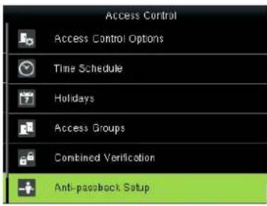
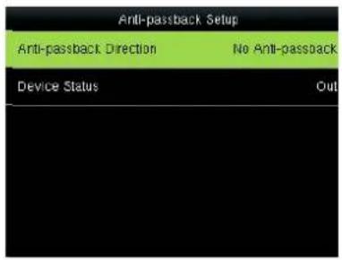
Press ▼ to select
Anti-Passback Setup and press OK
Enter to Anti-Passback Setup interface
Anti-pass back
Out anti-passback: If the device does not store the record of a person, the person can check out after the first comparison. In case that a person's record has been stored in the device, an alarm will be raised when the person checks out without the corresponding entry record in the device. If only out anti-passback is enabled, entry is allowed at any time.
In anti-passback: If the device does not store the record of a person, the person can check in after the first comparison. In case that a person's record has been stored in the device, an alarm will be raised when the person checks in without the corresponding exit record in the device. If only in anti-passback is enabled, exit is allowed at any time.
In/out anti-passback: If the device does not store the record of a person, the person can check in and out after the first comparison. In case that a person's record has been stored in the device, an alarm will be raised when the person checks in or out without a corresponding exit or entry record in the device.
No anti-passback: The door will be opened only when a person is authenticated by the master host.
Device status
Entry control: When a device is used to control entry, the device saves only the entry records.
Exit control: When a device is used to control exit, the device saves only the exit records.
None: When the status of a device is set to None, the anti-passback function is disabled on the device.
3) modify device's Wiegand output format
When the two devices are communicating, only Wiegand signals without device ID are received. Enter device menu->communication option >Wiegand option or enter software- basic setting- device management-Wiegand, to modify "defined format" as "wiegand26 without device ID".
4) enroll user
The user must be on master machine and slave machine at the same time, and user PIN must be the same. Therefore, it is necessary to enroll user on master machine and slave machine at the same time.
5) connection instruction
Wiegand communication is adopted for master machine and slave machine.
Refer to the following for connection:
| Master | Slave | |
| IND0 | <----> | WD0 |
| IND1 | <----> | WD1 |
| GND | <----> | GND |
Statement on Human Rights and Privacy
Dear Customers:
Thank you for choosing the hybrid biometric products designed and manufactured by us. As a world-renowned provider of biometric technologies and services, we pay much attention to the compliance with the laws related to human rights and privacy in every country while constantly performing research and development.
We hereby make the following statements:
- All of our fingerprint recognition devices for civil use only collect the characteristic points of fingerprints instead of the fingerprint images, and therefore no privacy issues are involved.
- The characteristic points of fingerprints collected by our products cannot be used to restore the original fingerprint images, and therefore no privacy issues are involved.
- We, as the equipment provider, shall not be held legally accountable, directly or indirectly, for any consequences arising due to the use of our products.
- For any dispute involving the human rights or privacy when using our products, please contact your employer directly.
Our other police fingerprint equipment or development tools will provide the function of collecting the original fingerprint image of citizens. As for whether such a type of fingerprint collection constitutes an infringement of your privacy, please contact the government or the final equipment provider. We, as the original equipment manufacturer, shall not be held legally accountable for any infringement arising thereof.
Note: The law of the People's Republic of China has the following regulations regarding the personal freedom:
- Unlawful arrest, detention or search of citizens of the People's Republic of China is prohibited; infringement of individual privacy is prohibited.
- The personal dignity of citizens of the People's Republic of China is inviolable.
- The home of citizens of the People's Republic of China is inviolable.
- The freedom and privacy of correspondence of citizens of the People's Republic of China are protected by law.
At last we stress once again that biometrics, as an advanced recognition technology, will be applied in a lot of sectors including e-commerce, banking, insurance and legal affairs. Every year people around the globe suffer from great loss due to the insecurity of passwords. The fingerprint recognition actually provides adequate protection for your identity under a high security environment.
Environment-Friendly Use Description

The Environment Friendly Use Period (EFUP) marked on this product refers to the safety period of time in which the product is used under the conditions specified in the product instructions without leakage of noxious and harmful substances.
The EFUP of this product does not cover the consumable parts that need to be replaced on a regular basis such as batteries and so on. The EFUP of batteries is 5 years.
Names and Concentration of Toxic and Hazardous Substances or Elements
O: Indicates that this toxic or hazardous substance contained in all of the homogeneous materials for this part is below the limit requirement in SJ/T11363-2006.
x: Indicates that this toxic or hazardous substance contained in at least one of the homogeneous materials for this part is above the limit requirement in SJ/T11363-2006.
Note: 80% of the parts in this product are manufactured with non-hazardous environment-friendly materials. The hazardous substances or elements contained cannot be replaced with environment-friendly materials at present due to technical or economical constraints.
- Important Claim
- Contents
- Contents....I
- Instruction for Use....1
- Main Menu 5
- User Management 7
- User Role 14
- Communication Setting....15
- System....21
- Personalize....26
- Data Mgt....31
- Access Control Setting....34
- USB Manager 42
- Attendance Search....44
- Print★ 45
- Short Message....46
- Work Code....48
- AutoTest 50
- System Information....51
- Appendix 52
- Instruction for Use
- Finger Placement
- Verification Modes
- 1: N Fingerprint Verification
- 1:1 fingerprint verification
- Notes:
- Password Verification
- ID Card Verification
- ID Card Only
- ID + Facial Verification
- Status of icons
- Main Menu
- User Management
- Adding a User
- Entering a User ID
- Tip: The terminal supports the 1- to 9-digit user IDs by default.
- Modifying the user role
- Enrolling a Fingerprint
- Enrolling an ID Card
- Enrolling a Password
- Enroll Photo
- Access Control Role
- Verification mode:
- Apply Group Time Period:
- Query a User in All User
- Query by User ID and Name
- Edit and delete a User
- Display Style
- User Role
- Communication Setting
- Ethernet
- Serial Comm★
- PC Connection
- Cellular Data Network★
- Wireless Network★
- Operation
- ADMS★
- Wiegand Setup
- Wiegand INput
- Wiegand OUTput
- System
- Date/Time
- Attendance
- Fingerprint
- Reset
- USB Upgrade
- Personalize
- User Interface
- Voice
- Bell Schedules
- Adding a Bell
- Edit and delete a Bell
- Options
- Punch State Options
- Data Mgt.
- Delete Data
- Backup Data
- Restore Data
- Access Control Setting
- Access Control Options
- Notice
- Time Schedule
- Holiday setting
- Access Groups
- Notice:
- 2) Edit and Delete group time zone
- Set Combined Verification
- Anti-pass back
- Duress alarm parameter
- Operation:
- USB Manager
- Download
- Upload
- Download Options
- Attendance Search
- Attendance Record
- Print★
- Data Field Setup
- Printer Options
- Short Message
- Public, Personal and Drafts lists
- Message Options
- Employee check SMS
- Work Code
- Add a work code
- All Work Codes
- work code Options
- AutoTest
- System Information
- Appendix
- Appendix 1 Description of Text Input Operation
- Appendix 2 Image Upload Rules
- Appendix 3 anti-pass back
- 【overview】
- 【working principle】
- 【function】
- 【operation】
- 1) Select model
- 2) Menu setting
- Anti-pass back
- Device status
- Statement on Human Rights and Privacy
- Environment-Friendly Use Description
Brand : ZKTeco
Model : G2
Category : Access Control System