
Bit One HD - Audio/video converter AUDISON - Free user manual and instructions
Find the device manual for free Bit One HD AUDISON in PDF.


| Product Type | Digital Signal Processor (Audio/Video Converter) |
| Brand | Audison |
| Model | Bit One HD |
| Dimensions (W x H x D) | 148 x 43.6 x 233 mm (5.82 x 1.7 x 9.17 in) |
| Weight | 1.775 kg (3.9 lbs) |
| Power Supply Voltage | 11 - 15 VDC (operating 7.5 - 14.4 VDC) |
| Idling Current | 0.75 A |
| Fuse | 2 A (Blade type) |
| Analog Inputs | 12 High-Level (Speaker In) up to 15 V RMS, 6 Low-Level (Pre In) up to 6.5 V RMS, 1 Stereo AUX up to 5 V RMS |
| Digital Inputs | 2 Optical S/PDIF (up to 192 kHz / 24 bit) |
| Outputs | 13 Low-Level (Pre Out) 4 V RMS, 2 Digital AD Link (Ch1-8 and Ch9-13) |
| Signal Processing | 24-bit / 96 kHz, 13 channels |
| Crossover Filters | Full, High Pass, Low Pass, Band Pass with slopes up to 48 dB/oct (Linkwitz, Butterworth, Bessel) |
| Equalization | 13 parametric EQs (11 bands each), 5-band main EQ, automatic de-equalization, dynamic EQ, bass boost |
| Time Alignment | Delay 0 - 22 ms, Distance 1.4 - 756 cm |
| PC Connection | Micro USB (USB 1.1 / 2.0 / 3.0 compatible) |
| Software Requirements | Windows XP / Vista / 7 / 8 / 10 (32/64 bit), 1.5 GHz processor, 1 GB RAM |
| Remote Control | DRC MP (Digital Remote Control) with volume, balance, fader, sub, preset selection |
| Cleaning Instructions | Use a soft cotton cloth lightly damped with water. Do not use aggressive cleaning agents or abrasive cloths. |
| Safety Notes | Ensure correct power polarity; use specified fuse; disconnect amplifiers before firmware update. |
| Firmware Updates | Available via www.audisonbitdrive.eu; rescue mode for recovery if needed. |
Frequently Asked Questions - Bit One HD AUDISON
User questions about Bit One HD AUDISON
0 question about this device. Answer the ones you know or ask your own.
Ask a new question about this device
Download the instructions for your Audio/video converter in PDF format for free! Find your manual Bit One HD - AUDISON and take your electronic device back in hand. On this page are published all the documents necessary for the use of your device. Bit One HD by AUDISON.
USER MANUAL Bit One HD AUDISON

natural_image
Futuristic white concept car with blue accents against a gray background, no visible text or symbols.

bit One HD
High Definition Signal Processor
USER'S MANUAL
rev. 1.0

5.3 PERSONAL COMPUTER and DIGITAL REMOTE CONTROL (DRC MP)....10
5.4 LOW-LEVEL AND DIGITAL INPUT SIGNALS....11
5.5 HIGH-LEVEL INPUT SIGNALS....12
5.6 OPTICAL 1/OPTICAL 2 DIGITAL INPUT DIGITAL SIGNALS....12
5.7 OUTPUT SIGNALS 14
- bit One HD SOFTWARE AND DRIVERS - INSTALLATION GUIDE 16
6.1 SOFTWARE INSTALLATION GUIDE 16
6.2 DRIVERS INSTALLATION GUIDE FOR WINDOWS XP, VISTA, 7/8/10....18
6.3 bit One HD SOFTWARE UNINSTALL....18
- bit One HD SETUP WITH PC 19
7.1 OFFLINE MODE 19
7.2 TARGET MODE....20
7.3 MASTER LOW-LEVEL INPUTS SELECTION 22
7.4 MASTER HIGH-LEVEL INPUTS SELECTION 28
7.5 MASTER OPTICAL 1 INPUT SELECTION....34
- bit One HD INSTALLATION GUIDE USING A PC....37
8.1 FEATURES....37
8.2 MAIN MENU: "FILE" 38
8.3 MAIN MENU: "CONFIG" 40
8.4 MEMORY 42
8.5 SELECT A CHANNEL 43
8.6 CHANNEL MAP 43
8.7 FILTER SETTINGS 44
8.8 SET DISTANCE AND DELAY 46
8.9 EQ SETTINGS 48
8.10 OUTPUT LEVEL 51
8.11 SELECT INPUT 52
8.12 SETUP 52
8.13 DEVICE INFO....54
- TROUBLESHOOTING 55
9.1 SYNCHRONIZATION WITH THE PC 55
9.2 BACKGROUND NOISE....55
9.3 FIRMWARE UPGRADES....55
9.4 RESCUE MODE 57
- TECHNICAL SPECIFICATIONS ....59
1. PRODUCT DESCRIPTION
The bit One HD is a digital signal processor developed to obtain outstanding performance from car audio systems.
The main features include 2 optical SP/DIF inputs, 12 analog inputs, 13 digital outputs and Hi-Res 24bit/96kHz internal signal processing which, along with many other functions make it a powerful and versatile product, ready for future evolutions.
To this end, several hardware updates have already been planned. These updates will enable the product to adapt to future technological innovations, providing the ability of interfacing with OEM systems which, at the time of the product conception, were merely hypothetical.
The all-round software and the endless dedication of the R&D team, aimed at improving and updating the product, make the bit One HD the reference device on the market, keeping its leadership for many years to come and rewarding the user with the quality of its sound and with a long-lasting investment.
2. PACKAGING CONTENTS
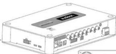
- bit One HD - Signal Interface Processor
natural_image
Line drawing of a wireless device with ports and connectors (no text or symbols)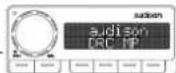
- DRC MP (Digital Remote Control) Control Panel
- Multipolar cable, Speakers Input:
- Multipolar cable, Controls
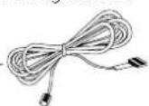
- RVA cable 4.5 m
- Jack/RCA Stereo Adapter
- N.2 x 5.0 m / 196,85" AC Link (RJ-12) cable
- N.2 x 5.0 m / 196,85" AD Link (LAN class 5S - RJ45) cable
- 1.8 m/ 70,8661" USB cable:
- N. 4 4,2 x 32 mm self-tapping, cross-head fixing screws
- 4.5 m / 177,16" DRC / AC Link cable
- N. DRC MP holder Kit.
- CD ROM including:
Software bit One HD
This Advanced Manual (.pdf format)
Audio test tracks
- DVD comprising:
Test tracks encoded with Dolby Digital 5.1
- Quick Start Guide bit One HD
- Quick Start Guide DRC MP
- Warranty
WARNING: a PC provided with Windows XP, Windows Vista, Windows 7 or Windows 8, operating system, 1.5 GHz minimum processor speed and 1 GB RAM minimum memory, is required to install the software and setup the bit One HD.





natural_image
Three types of cables with connectors and connectors, no text or symbols visible




3. bit One HD AND DRC MP INSTALLATION
bit One HD:
External dimensions

Mounting dimensions


DRC MP:

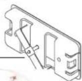
How to install the DRC MP

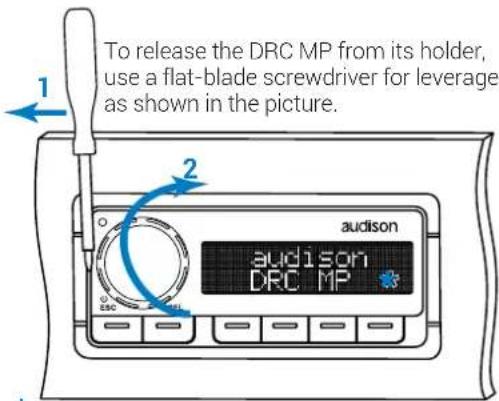
WARNING do not use aggressive cleaning agents or abrasive cloth to clean the display. Simply use a soft cotton cloth lightly damped with water.
4. CONNECTION PANELS - DESCRIPTION
4.1 INPUT SIGNALS

1. SPEAKERS IN hi-level MASTER input (see section 5.5)
Ch1 - Ch2 - Ch3 - Ch4 - Ch5 - Ch6 - Ch7 - Ch8 - Ch9 - Ch10 - Ch11 - Ch12
HI LEVEL MASTER inputs to connect the amplified signal wires coming from the main analog source. Input sensitivity automatically adjustable from 2 to 15 V RMS (see sec. 7.4.3). Channels Ch1 - Ch2 feature the AUTO TURN ON (ART) function through the connection with the source speakers outputs. This function can be excluded using the PC software (see section 7.4.1). The input signals are interfaced to the bit One HD via wiring with a multi-pin 24 poles connector as described below.

Remark: when connecting a speaker input cable, use Faston crimp terminals.
2. PRE IN low-level MASTER inputs (see section 5.4.1)
Ch1 - Ch2 - Ch3 - Ch4 - Ch5 - Ch6
To connect RCA cables coming from the main analog signal source. If these inputs are used, the MASTER SPEAKER IN inputs can not be used.
3. AUX auxiliary low-level STEREO inputs (see section 5.4.2)
To connect the RCA cables coming from additional analog signal sources.
4. OPTICAL IN digital inputs (see section 5.6)
Bit One HD accepts input PCM signals up to 192 kHz / 24 bit sampling frequency rate. So DOLBY DIGITAL (AC3) multi-channel signals coming from audio/video sources (such as the audio of a film in DVD) or DTS can not be reproduced. These inputs can be selected using the external DRC control or activated using the terminal see section. 4.3.4).
OPTICAL 1. Connect an optical fiber cable with TOSLINK connector OPTICAL 2. Connect an optical fiber cable with TOSLINK connector
Remark: when performing the installation of fiber optic cables, the minimum bending radius should be 40 mm. A bending with higher radius value may cause the cable to break and the consequent disruption of the digital signal.
4.2 OUTPUT SIGNALS

- PRE OUT low-level analog signal (4 Volt RMS) (see section 5.7.2)
Ch1 - Ch2 - Ch3 - Ch4 - Ch5 - Ch6 - Ch7 - Ch8 - Ch9 - Ch10 - Ch11 - Ch12 - Ch13
To connect the RCA cables going to the system's amplifiers.
- AD Link - OUT digital signal (see section 5.7.1)
S/PDIF standard digital signal (Ch1÷Ch13) to connect amplifiers provided with the specific AD Link input.
AD LINK 1: S/PDIF standard digital signal (Ch1÷Ch8) to connect amplifiers provided with the specific AD Link input
AD LINK 2: S/PDIF standard digital signal (Ch9÷Ch13) to connect amplifiers provided with the specific AD Link input
- AC Link: Connection socket to control the amplifiers provided with AC Link connection (see section 5.7.1).
AC LINK 1: Connection socket to control the amplifiers (Ch1÷Ch8) provided with AC Link connection.
AC LINK 2: Connection socket to control the amplifiers (Ch9÷Ch13) provided with AC Link connection.
Remark: the Remote Out signal is available on the AC LINK 1 / AC LINK 2 connection plugs and is active to the amplifiers supporting this function (Audison AV amplifiers with AV bit IN input).
- RVA (Remote Volume Aux): control signal output to connect to the master source AUX input, to enable the "AIS - Auto Input Switch" function. (see 5.4.3 - 5.6.1; 8.3.5).


4.3 INPUTS - REMOTE CONTROL OUTPUTS AND POWER SUPPLY


1. POWER SUPPLY / REMOTE IN-OUT (see section 5.1)
+BATT 12V: positive connection terminal for car 12V power supply
-BATT: negative connection terminal for car 12V power supply.
WARNING: make sure the connection polarity is as indicated on the terminals. A misconnection may result in damage to the bit One HD. After applying a 12V power, wait at least 10 seconds before turning the bit One HD on.
REMOTE IN: for the processor remote turn-on through one or multiple signal sources, featuring Rem Out control.
WARNING: the bit One HD must be switched on before the amplifiers connected are turned on. It is necessary to connect the sources Remote Out to the bit One HD Remote In and then the bit One HD Remote Out to the Remote In of the other devices/amplifiers connected to the bit One HD (section 5.1).
REMOTE OUT: for the remote turn-on of the other devices/amplifiers connected to the processor. The REMOTE OUT output has a current capability of 130 mA (it can also drive an automotive relay). The processor only takes 7 seconds to supply the REM OUT to the output after turn on
Remark: the Remote Out signal is available on the AC LINK 1 / AC LINK 2 connection plugs and is active to the amplifiers supporting this function (Audison AV amplifiers with AV bit IN input).
-
DRC MP: connection plug for the DRC MP (Digital Remote Control), to control the processor's functions
-
OEM INTERFACE: terminals for future use.
-
CONTROLS: terminals to activate and control input audio signals.
-
OVERALL PRESET: selection of a bit One HD memory previously saved via PC software (see section 8.4). This function is activated by connecting the terminal to +12V.
- OPTICAL 1 SELECT: selection of the OPTICAL 1 input. This function is activated by connecting the terminal to +12V.
- OPTICAL 2 SELECT: selection of the OPTICAL 2 input. This function is activated by connecting the terminal to +12V.
- AUX SELECT: selection of the AUX. This function is activated by connecting the terminal to +12V.
The control signals are interfaced to the bit One HD via wiring with a multi-pin 4 poles connector as described below.

- CNK: terminals for future use.
-
LCK: terminals for future use.
-
USB (section 5.3)
USB connection plug (Female type micro), to connect the processor to a PC and manage its functions through the bit One HD software. The standard connection is USB 1.1/2.0/3.0 compatible.
- UPDATE MODE: Switch ON enables the update in RESCUE MODE (section 9.4) and the bit One HD logo will start flashing.
- FUSE: Blade 2A protection fuse. When needing to replace the fuse, only use the same type and value as the original.
5. CONNECTIONS
5.1 POWER SUPPLY AND REMOTE TURN ON
POWER SUPPLY

WARNING: to power the bit One HD,
use 1 mm 2 (16 AWG) min. cables

5.2 HOW TO TURN THE bit One HD ON/OFF
The bit One HD is on when the Audison logo lights up in blue. After receiving the turn on input the bit One HD takes 6 seconds to start working. It can be turned on / off in the following ways:
- Through the DRC MP main control switch (to turn on). Keep the DRC MP main control knob pressed (to shut down). In this case no other Remote In connections are required, but they can coexist (see section 5.1).
- By connecting the REMOTE IN terminal with a Remote Out signal coming from an after-market audio source.
- Through the SPEAKER IN CH1-CH2. The AUTO TURN ON (ART) is activated by connecting the amplified head unit output to the SPEAKER IN CH1-CH2 input channel. This function can be enabled/disabled using the bit One HD PC software section 7.4.1).
5.3 PERSONAL COMPUTER and DIGITAL REMOTE CONTROL (DRC MP)
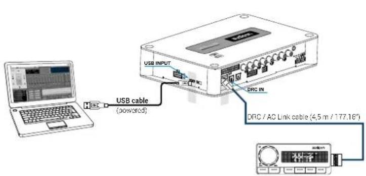
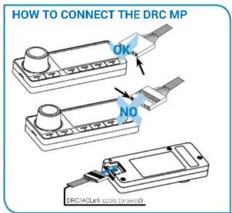
5.4 LOW-LEVEL AND DIGITAL INPUT SIGNALS
5.4.1. PRE IN - Ch1/Ch6 analog STEREO signal

flowchart
graph TD
    A["After Market Head Unit"] --> B["Front Left"]
    A --> C["Front Right"]
    A --> D["REAR LEFT"]
    A --> E["REAR RIGHT"]
    A --> F["CENTER"]
    A --> G["SUB"]
    B --> H["Switch 1"]
    C --> I["Switch 2"]
    D --> J["Switch 3"]
    E --> K["Switch 4"]
    F --> L["Switch 5"]
    G --> M["Switch 6"]
    H --> N["Control Unit"]
    I --> N
    J --> N
    K --> N
    L --> N
    M --> N
    N --> O["Output"]
    style A fill:#f9f,stroke:#333
    style B fill:#ccf,stroke:#333
    style C fill:#ccf,stroke:#333
    style D fill:#ccf,stroke:#333
    style E fill:#ccf,stroke:#333
    style F fill:#ccf,stroke:#333
    style G fill:#ccf,stroke:#333
MAX 6 PRE OUT
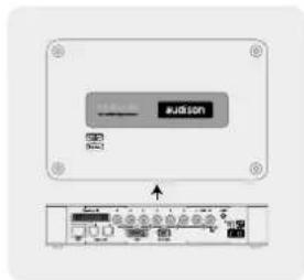
bit One HD Bottom Side
Selection of the MASTER PRE IN input
- Through the DRC MP, selecting the MASTER input.
- Through the MASTER input, using the bit One HD PC software
- Through the MASTER input, using the bit One HD PC software.
5.4.2. AUX - Left/Right - analog STEREO signal
Selection of the AUX IN input
- Through the DRC MP, selecting the AUX input.
-
Through the AUX SEL terminal (see section 4.3.4). This control is enabled by connecting the terminal at +12V.
-
Through the bit One HD PC software, selecting the AUX input.
-
Through the selection of the AUX input from the OEM source, using the "Auto Input Switch" function, via the bit One HD PC software (see section 5.4.3 - 7.3.8 - 7.4.8).
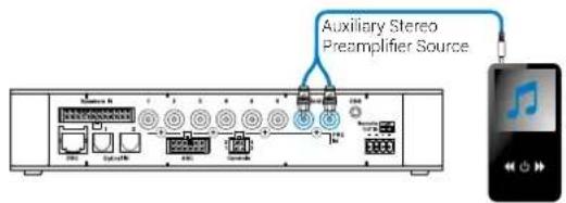
5.4.3. "AUTO INPUT SWITCH" AUX SIGNAL
Activate the "AUTO INPUT SWITCH" function on the AUX input via PC software to enable the bit One HD AUX input, each time the source AUX input is activated. When using this function the bit One HD volume can be controlled through the source volume (see section 7.3.8 - 7.4.8; 8.3.5).
Remark: when activating the "Auto Input Switch" function, the DRC/PC Software can no longer be used for the switch of the audio system inputs. The switch can be enabled through the audio system source, selecting the AUX or Master input. When the "AIS - Auto Input Switch" function is active and a bit Play HD is connected to the system along with Full DA amplifiers (AD LINK - AC LINK) the DRC MP will be disabled and will display the following: "DRC DISABLED".


5.5 HIGH-LEVEL INPUT SIGNALS

5.5.1. SPEAKER IN Hi-level MULTICHANNEL (max 12 CHANNELS)
bit One HD Bottom Side

flowchart
graph LR
    A["OEM HEAD UNIT"] --> B["OEM AMPLIFIER"]
    B --> C["MAX 12 CHANNELS INPUT"]
    C --> D["Output Panel"]
    style A fill:#f9f,stroke:#333
    style D fill:#ccf,stroke:#333
* CH1-CH2: Auto Turn On System (ART) (see section 7.4.1)
MASTER SPEAKER IN input selection
- Through the DRC MP, selecting the MASTER input.
- Through the MASTER input, using the bit One HD PC software.
5.6 OPTICAL 1/OPTICAL 2 DIGITAL INPUT SIGNALS

WARNING: the digital inputs accept up to 192 kHz / 24 bit stereo PCM signals. So DOLBY DIGITAL (AC3)
multi-channel signals coming from audio/video sources (such as the audio of a film in DVD) or DTS can not be reproduced. The output of these devices will therefore be set in STEREO mode for the signal to be reproduced.
*Remark: when performing the installation of fiber optic cables, the minimum bending radius should be 40 mm. A bending with higher radius value may cause the cable to break and the consequent disruption of the digital signal.
OPTICAL 1/OPTICAL 2 inputs selection
- Through the DRC MP, selecting the OPTICAL 1 / OPTICAL 2 input.
- Through the OPTICAL 1 SEL / OPTICAL 2 SEL terminal properly set up (see section 4.3.4). This control is activated by connecting the terminal at +12V.
- Through the selection of the OPTICAL 1/ OPTICAL 2 input via the bit One HD PC software.
- Through the selection of the OPTICAL 1/ OPTICAL 2 input on the OEM source, using the "Auto Input Switch" function, via the bit One HD PC software (see section 5.6.1 - 7.3.8 - 7.4.8).
5.6.1. "AUTO INPUT SWITCH" OPTICAL 1 / OPTICAL 2 SIGNALS.
Activate the "AUTO INPUT SWITCH" function on the OPTICAL 1 or OPTICAL 2 input via PC software to enable the bit One HD OPTICAL 1 or OPTICAL 2 input, each time the source AUX input is activated. When using this function the bit One HD volume can be controlled through the source volume (see section 7.3.8 - 7.4.8; 8.3.5).
Connect the bit One HD OPTICAL 1 or OPTICAL 2 input to the audio source and the processor's RVA input to the Master source AUX input (Head Unit).
WARNING: the "Auto Input Switch" function activation, and the subsequent selection of the auxiliary input to be used, may cause the loss of the other two auxiliary inputs not selected.
Remark: when activating the "Auto Input Switch" function, the DRC/PC Software can no longer be used for the switch of the audio system inputs.
The switch can be enabled through the audio system source, selecting the AUX or Master input.
When the "AIS - Auto Input Switch" function is active and a bit Play HD is connected to the system along with Full DA amplifiers (AD LINK - AC LINK) the DRC MP will be disabled and will display the following: "DRC DISABLED".

5.7 OUTPUT SIGNALS
AD LINK-OUT / AC LINK
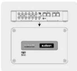
bit One HD Top Side
5.7.1. OUTPUT TO AN AMPLIFIERS SYSTEM PROVIDED WITH AD LINK AND AC LINK CONNECTION (THESIS TH / AV AMPLIFIERS)
(see section 7.3.12 - 7.4.12 - 7.5.5)


CHA:1-2 CHB:3-4

CH A: 5-6 CH B: 7-8
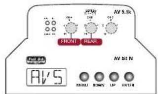
CHA:1-2 CHB:3-4 CHC:5
Remark: the output channels are 13 in total. The sum of the channels of the amplifiers connected must not exceed 13. To increase the number of channels, however, the same function (AMP ID) can be assigned to more than one amplifier.
5.7.2. OUTPUT TO AN AMPLIFIERS SYSTEM WITH PRE INPUT
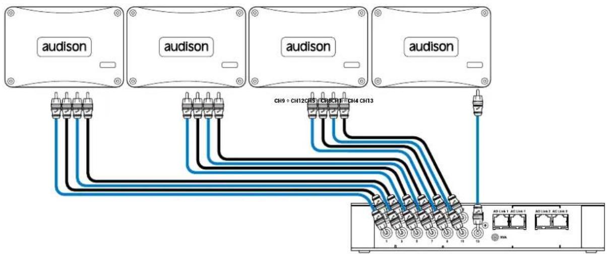
5.7.3. OUTPUT TO AN AMPLIFIERS SYSTEM PROVIDED WITH AD LINK AND AC LINK CONNECTIONS (THESIS TH) AND AMPLIFIERS PROVIDED WITH PRE INPUT (see section 7.3.12 - 7.4.12 - 7.5.5).

Remark: the output channels are 13 in total. The sum of the analog and digital outputs (AD Link) must not exceed the number of available channels.
6. bit One HD SOFTWARE AND DRIVERS - INSTALLATION GUIDE
6.1 SOFTWARE INSTALLATION GUIDE
- Insert the "bit One HD Setup CD" into the CD-Player of the PC you are going to use
- Windows XP: select "My Computer" from the Windows START menu;
Windows Vista: select "Computer" from the Windows START menu;
Windows 7: select "Computer" from the Windows START menu;
Windows 8/10: click on the DESKTOP icon;
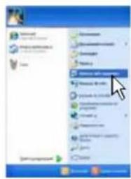

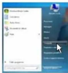

Windows XP Windows Vista Windows 7 Windows 8/10
- Windows XP: right-click your mouse on the "bit One HD Setup CD" icon and select "Explore"; Windows Vista: right-click your mouse on the "bit One HD Setup CD" icon and select "Explore"; Windows 7: right-click your mouse on "bit One HD Setup CD" and select "Open"; Windows 8/10: double click on the Computer icon.
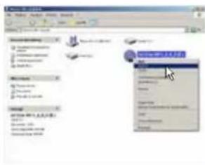


natural_image
Close-up of white daisies with yellow centers against a blue sky background (no text or symbols)Windows XP Windows Vista Windows 7 Windows 8/10
- Windows XP: double click on the "setup" icon;
Windows Vista: double click on the "setup" icon;
Windows 7: double click on the "setup" icon;
Windows 8/10: select the CD ROM drive and double click on setup icon.


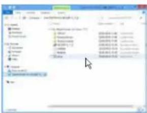
Windows XP Windows Vista Windows 7 Windows 8/10
- Windows XP: select NEXT to go on with the installation, CANCEL to interrupt it; Windows Vista: select NEXT to go on with the installation, CANCEL to interrupt it; Windows 7: select NEXT to go on with the installation, CANCEL to interrupt it; Windows 8/10: select NEXT to go on with the installation, CANCEL to interrupt it

- Windows XP: select I Agree and then NEXT; Windows Vista: select I Agree and then NEXT; Windows 7: select I Agree and then NEXT; Windows 8/10: select I Agree and then NEXT;

- Windows XP: select
- Everyone if you have the system administrator privileges, so, once installed, the program can be used by anyone who uses that PC; - Just me if you want that, once installed, the program can only be used by yourself as single system user. Then select NEXT;
Windows Vista: select
- Everyone if you have the system administrator privileges, so, once installed, the program can be used by anyone who uses that PC; - Just me if you want that, once installed, the program can only be used by yourself as single system user. Then select NEXT;
Windows 7: select
- Everyone if you have the system administrator privileges, so, once installed, the program can be used by anyone who uses that PC; - Just me if you want that, once installed, the program can only be used by yourself as single system user. Then select NEXT;
Windows 8: select
- Everyone if you have the system administrator privileges, so, once installed, the program can be used by anyone who uses that PC; - Just me if you want that, once installed, the program can only be used by yourself as single system user. Then select NEXT;

- Windows XP: go on and complete the installation procedure, then select CLOSE to exit the installation; Windows Vista: go on and complete the installation procedure, then select CLOSE to exit the installation; Windows 7: go on and complete the installation procedure, then select CLOSE to exit the installation; Windows 8/10: go on and complete the installation procedure, then select CLOSE to exit the installation;

- The bit One HD PC software is now installed in your system.
6.2 DRIVERS INSTALLATION GUIDE FOR WINDOWS XP, VISTA, 7/8/10
- Turn the bit One HD on.
- Connect the USB cable located on the appropriate connector on the bit One HD to the USB available on the PC.
WARNING: when connecting a laptop PC via USB cable to the bit One HD while the device is turned on, the laptop has to work with its own battery, keeping it disconnected from the mains adapter (external power supply). Once the connection between the laptop PC and the bit One HD is established, you can immediately connect the computer, if necessary, through the mains adapter.
- Windows XP: the PC will recognize the bit One HD interface and will automatically install the driver;


Windows XP Windows XP
Windows Vista: the PC will recognize the bit One HD interface and will automatically install the driver;


Windows Vista Windows Vista
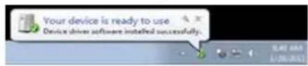
Windows 7/8/10: the PC will recognize the bit One HD interface and will automatically install the driver;

Windows 7/8/10 Windows 7/8/10
- The peripheral device has been installed correctly and is ready for use.
Remark: the bit One HD uses HID drivers already integrated in Windows. For this reason, they are not included in the CD and will always install automatically.
6.3 bit One HD SOFTWARE UNINSTALL
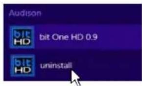
To uninstall the bit One HD PC software you can use the link listed on the menu: Start / All Programs / bit One HD / uninstall
7. bit One HD SETUP WITH PC
To adjust the bit One HD functions a software is required. The processor needs to be connected to the PC and turned on. After installing the software, start it by selecting the icon shown on your desktop.

The first window is the startup page where one of the following modes needs to be selected:
- OFFLINE mode, bit One HD not connected;
- TARGET mode, bit One HD connected;
- RESCUE mode, bit One HD connected for Update/Rescue
(see section 9.4).

To select the startup mode select the corresponding entry on the drop down menu, then press ENTER or double click on the bit One HD image.
7.1 OFFLINE MODE
In this case even if the bit One HD processor is connected to the PC, it does not interact with the software.
The OFFLINE mode can be used to work on the software to get familiar with the processor multiple functions without connecting the bit One HD to the PC. For more information on the specific functions see section 7.2 (TARGET mode).
The software is pre-set to start with a 3-way + stereo Sub active multi-amplified system.
To set a new "virtual" system, and so to change the inputs and select the outputs, the function I/O Configuration Wizard in the "Config" window of the software main menu needs to be selected.
Follow the same instructions as per TARGET mode (see section 7.2).

Here is how the bit One HD software appears when started in OFFLINE mode
Remark: how to change the size of the PC software window
- To make the window full-screen, click on the Enlarge button or double click on the title bar of the PC software window.
- To restore the previous size from full-screen, click on the Reset button or double click on the title bar on the window.
- To resize the PC software window (make it smaller or larger), position the mouse pointer on one edge or corner of the window. When the mouse pointer becomes an arrow with a double point, drag the edge or corner to make the window larger or smaller.

natural_image
Pure geometric corner lines without any text, numbers, or symbols7.2 TARGET MODE
In this case the bit One HD processor must be connected to the PC and turned on, otherwise the software won't even show the TARGET entry as selectable on the startup window.
At this point you need to have in mind the system you want to develop beforehand, since from this moment, to change any of the settings you will have to go through the guided procedure all over again.
More specifically the guided procedure will request:
- Which are the main inputs to be used (high or low level). This choice will not prevent the user from adding auxiliary low level or digital sources. The guided procedure changes according to the selected choice.
- If the product will be turned on through "HI LEVEL TURN ON" (ART).
-
Which auxiliary inputs will be used (e.g.: AUX or OPTICAL IN).
-
Which kind of signals will be allocated to the main inputs (e.g.: Front Left or Center or Subwoofer etc.).
- Which speakers are installed in the system (e.g.: 3-way Front or stereo Sub or 2-way Rear etc.).
- If the system features passive crossovers managing speaker groups (e.g.: 3-way system with active mid-low).
- If the system features any speaker connected through the AC Link.
WARNING: during this procedure the bit One HD RCA / AD LINK - AC LINK outputs to the amplifiers should be disconnected.
PC software startup in Target mode.
Screen
image
sequence
When starting up, if correctly interfaced to the PC (with software and drivers properly installed), the software will appear on the screen as shown in the images.

If, once the scanning is completed, the bit One HD can not be found (Fig.3):
- check if the bit One HD is on (check if the Audison logo is lit up);
- check if the USB cable is properly connected;
- select OK to search again for the bit One HD;
- select CANCEL to start the OFFLINE mode.

Screen image sequence
The bit One HD is set up by default as detailed below: Input Hi Level Master :
- CH1 Front Left Full
- CH2 Front Right Full
- CH3 Rear Left Full
- CH4 Rear Right Full
AUTO Turn ON Hi Level: Active
Output Analog (Pre Out):
- CH1: Front Left Woofer - CH2: Front Right Woofer
- CH3: Front Left Midrange - CH4: Front Right Midrange
- CH5: Front Left Tweeter - CH6: Front Right Tweeter
- CH7: Rear Left Woofer - CH8: Rear Right Woofer
- CH9: Rear Left Tweeter - CH10: Rear Right Tweeter
- CH11: Center Tweeter - CH12: Center Woofer
- CH13: Subwoofer.
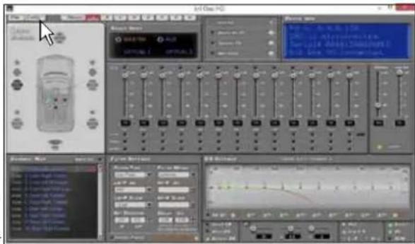
At this point you need to have in mind the system you want to develop beforehand, since from this moment, to change any of the settings you will have to go through the guided procedure all over again
Select I/O Configuration Wizard from the Config menu.

5
1. Guided procedure to set up the desired car audio system.
Press NEXT to continue with the setting. Press CANCEL to exit the program.

6
2. Inputs selection
- Select the main inputs (MASTER) type (Low Level, High Level or optical 1) used. To change this setting at a later stage, the I/O Configuration Wizard guided procedure will have to be performed again.
- Select among the available auxiliary inputs (AUX - OPTICAL 1 - OPTICAL 2) the ones which will be used. The setting can be changed at a later stage by selecting "Config / External Source" on the software main menu
Press BACK to go back to the previous step. Press NEXT to go ahead with the setup procedure.

7
High Level section 8.4
Low Level section 8.3
Optical section 8.5
7.3 MASTER LOW-LEVEL INPUTS SELECTION
Screen image sequence
1. How to set up the low-level inputs
The inputs can be selected by clicking on the system's loudspeakers assigning the corresponding channel number (Ch1÷Ch6).
For the Low Level inputs the following input channels are available: Front Left Full, Front Right Full, Rear Left Full, Rear Right Full, Center Full, Subwoofer.
Press BACK to go back to the previous step.
Press NEXT to go ahead with the setup procedure.
Press CANCEL to exit the program.

1
2. How to calibrate the MASTER inputs levels
Calibration is absolutely required to adapt the bit One HD inputs sensitivity to the signal coming from the source.
Press BACK to go back to the previous step.
Press NEXT to go ahead with the inputs calibration.
Press SKIP to bypass the inputs calibration procedure.

②
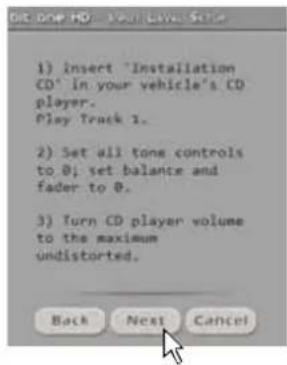
Follow the instructions listed below:
- insert the supplied CD:
- insert the "Setup CD" if the head unit in use is an AUDIO CD Player
- insert the "TEST SIGNAL DVD" if the head unit in use is a Dolby Digital (AC3) "Audio Car Theatre 5.1" featuring analog outputs, or an analog audio system featuring a central channel.
- play track 1 (press Play);
- set all tone controls to zero (0);
- set balance and fader to center (0);
- adjust the head unit volume to the maximum undistorted output level.
Press BACK to go back to the previous step.
Press NEXT to go ahead with the setup procedure.
Press CANCEL to exit the program.
Remark: the calibration is essential to adapt the bit One HD sensitivity to the signal coming from the source.
WARNING: the head unit level must be elevated to the maximum undistorted level. If the head unit level can not be tested in advance, bring the volume adjustment to approximately 80% of its maximum excursion. If the head unit output level is set at a lower level the bit One HD will produce a ground noise (hissing sound). Should such noise come from the bit One HD during reproduction, the calibration procedure will need to be repeated at higher volume.
Screen image sequence
3. Automatic calibration
A progress bar and specific messages show the procedure's implementation. Once the procedure is completed, the window will show the message "Press Next to Continue".
Press BACK to go back to the previous step. Press NEXT to go ahead with the setup procedure. Press CANCEL to exit the program.

Once the procedure is completed the window will show the sensitivity levels setup according to the source interfaced with the bit One HD. This window is active and a further manual sensitivity adjustment can be performed.
Press BACK to go back to the previous step. Press NEXT to go ahead with the setup procedure. Press CANCEL to exit the program.
ERROR MESSAGE MAY APPEAR
"Input Level too low"
Should a message informing the user that the input signal is too low appear when the inputs calibration is completed, proceed as follows:
Press BACK to go back to the previous step, check the inputs connection to the bit One HD and repeat the calibration procedure.
Press NEXT to go ahead with the setup procedure, check the inputs connection. And then proceed with the manual sensitivity calibration (see section 8.11).
Press CANCEL to exit the program.


4. Source de-equalization
Optional.
The de-equalization process performs an analysis of the electrical frequency response coming from the different channels of the OEM source, automatically applying an equalization contrary to the original one, thus generating a linear signal, much more suitable to drive high quality audio systems.
Regardless of the input channels used, the de-equalization will be performed for each functional group.

E.g.: even though Front Left Full and Front Right Full inputs are used, the software will perform the de-equalization also on Rear, Center and Subwoofer inputs as the processor will have to use the signals identified as Front to possibly also manage the Rear, Center and Subwoofer outputs.
Press BACK to go back to the previous step.
Press NEXT to go ahead with the setup procedure.
Press SKIP to bypass the de-equalization procedure.
5. De-equalization procedure
To perform this procedure, follow the instructions listed below:
- insert the "Setup CD" if the head unit in use is an AUDIO CD Player;
- play track 2 (press Play);
- set all tone controls to zero (0);
- set balance and fader to center (0);
- do not change the volume level previously set through the inputs level automatic calibration;
Press BACK to go back to the previous step.
Press NEXT to go ahead with the setup procedure.
Press CANCEL to exit the program.

5
6. De-equalization
A progress bar and specific messages show the procedure's implementation.
Once the procedure is completed, the window will show the message "Press Next to Continue".
Press BACK to go back to the previous step.
Press NEXT to go ahead with the setup procedure.
Press CANCEL to exit the program.

6
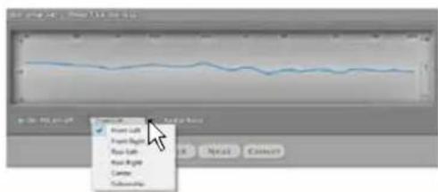
Once the procedure is completed the window will show the source equalization curves.
When activated, "De -Eq on/off" enables the
de-equalization to be performed, according to the specific curve of the source interfaced with the bit One HD.

Press BACK to go back to the previous step.
Press NEXT to go ahead with the setup procedure.
Press CANCEL to exit the program.
7. Master Input Delay
The presence of time delays on the inputs of the Head Unit interfaced to the bit One HD can be verified.
Press BACK to go back to the previous step.
Press NEXT to go ahead with the setup procedure.
Press CANCEL to exit the program.
Follow the instructions listed below:
- play track 3 (press Play);
- set all tone controls to zero (0);
- set balance and fader to center (0);
- do not change the volume level previously set through the inputs level automatic calibration;
Press BACK to go back to the previous step.
Press NEXT to go ahead with the setup procedure.
Press CANCEL to exit the program.
A progress bar and specific messages show the procedure's implementation.
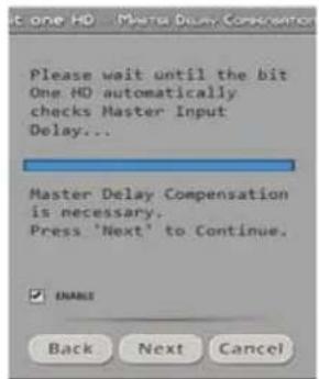
Once the procedure is completed, the window will show the message:
A) Master Delay compensation is not necessary: the source has no pre-set time delays.
Press BACK to go back to the previous step.
Press NEXT to go ahead with the setup procedure.
Press CANCEL to exit the program.
B) Master Delay compensation is necessary: the source has pre-set time delays. Tick the ENABLE box if you wish to align the time delays to 0 in the system setup.
Press BACK to go back to the previous step.
Press NEXT to go ahead with the setup procedure.
Press CANCEL to exit the program

7


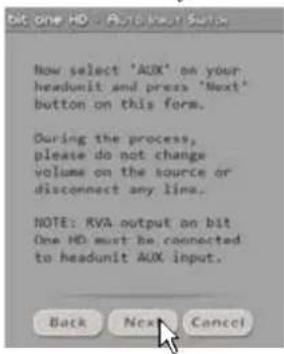
8. Auto Input Switch
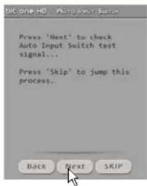
The automatic volume control for the auxiliary source (Aux - Optical 1/2) can be activated through the Head Unit volume control, if it is provided with an AUX input (see section 5.4.3.5.6.1:8.3.5).
Press BACK to go back to the previous step.
Press NEXT to go ahead with the setup procedure.
Press SKIP to bypass the procedure.
Follow the instructions listed below:
- connect the AUX IN inputs of the source (Head Unit)
to the bit One HD RVA input - select the source AUX IN input (Head Unit).
- set the source volume to the maximum undistorted level.
As previously set as per point 2 of this procedure.
Press BACK to go back to the previous step.
Press NEXT to go ahead with the setup procedure.
Press CANCEL to exit the program.
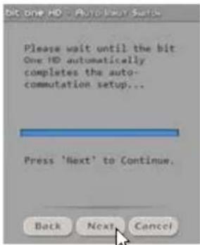
When the procedure is completed:
Press BACK to go back to the previous step.
Press NEXT to go ahead with the setup procedure.
Press CANCEL to exit the program.
8


9. Selection of the speakers available in the system
Speakers can be selected just by clicking on them.
If the left tweeter, left midrange or left woofer are selected, the software provides the ability to automatically activate also the right tweeter, right midrange or right woofer.
Once the software is started, this choice will affect the dedicated crossover type.
E.g.: if on the rear system only the woofers are activated, the software will only show a low-pass or band-pass filter as available.
If you want to use a coaxial system as rear channel, both tweeter and woofer need to be selected and then you need to specify that a passive crossover is connecting them, so the software will show a high-pass filter as available.
Press BACK to go back to the previous step.
Press NEXT to go ahead with the setup procedure.
Press CANCEL to exit the program.
From this point onwards a simulation of a system with the following components will be used:
- 3-way Front active;
- 2-way Rear active;
- 2-way center passive;
- Stereo Sub;
The 13 output channels of the bit One HD will be used.
⑨
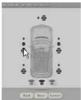
Window for the selection of the loudspeakers available in the system
10. Selection of passive crossovers for speaker groups.
The presence of passive crossovers managing speaker functional groups in complex systems can be provided by the user.
E.g.: the 3-way Front can be managed as:
- multi-amplified (6 output channels would be required);
- passive mid-high speakers + separately amplified woofer (4 output channels would be required);
- 3-way passive (2 output channels would be required).
While performing the setup, the software will automatically notify the return within the 8 output channel limit, the warning message will then disappear and the NEXT button will appear.
Press BACK to go back to the previous step.
Press NEXT to go ahead with the setup procedure
Press CANCEL to exit the program.

11. Processor outputs (Ch1÷Ch13) allocation.
The bit One HD features 13 output channels. On this specific step of the procedure, any signal can be assigned to each output channel.
E.g.: the outputs 1 and 2 can be assigned to the rear channels simply to avoid having to lengthen the cables going to the specific amplifier.
For a matter of convenience, if the output 1 is assigned to the left woofers, the software will automatically assign the output 2 to the right woofers. If during the procedure the output 1 is assigned also to the left mid-high speakers, the software will show a warning message. Change the allocation of one of the two numbers marked in red and the software will automatically select the first available channel.
Press BACK to go back to the previous step.
Press NEXT to go ahead with the setup procedure.
Press CANCEL to exit the program.

12. Selection of the amplifiers connected through the AD Link / AC Link connection system
If the system features amplifiers provided with the AD Link digital input and you want to connect them to the system, you need to select them on this setup procedure window. The CH1-CH8 output channels will be available on the AD LINK 1 socket, while the CH9-CH13 channels will be available on the AD LINK 2 socket.

Remark: remember to assign the corresponding Amp ID to the specific amplifier. The bit One HD will automatically recognize the identified amplifier.
Screen
image
sequence
13. System configuration successfully completed
Stop playing the Test track, remove the supplied Setup CD from the head unit CD player and then press OK.

13
7.4 MASTER HIGH-LEVEL INPUTS SELECTION
1. High-level inputs setup
You can assign to any of the processor input channels (Ch1÷Ch12) a specific name corresponding to the signal coming from the source. 12 input channels are available as listed below:
- Front Left Full / Tweeter / Midrange / Woofer;
- Front Right Full / Tweeter / Midrange / Woofer;
- Rear Left Full / Tweeter / Woofer;
- Rear Right Full / Tweeter / Woofer;
- Center Full / Tweeter / Woofer;
- Subwoofer.
A single component relating to the emission front can be selected or the full range emission front of the source used can be activated by ticking the FULL box.
Auto Turn On. The selection of "Power-On bit One HD from Hi Level" enables the bit One HD turn on through the amplified output (BTL) of the source (Head Unit) connected to the inputs CH1 and CH2.
Press BACK to go back to the previous step.
Press NEXT to go ahead with the setup procedure.
Press CANCEL to exit the program

①

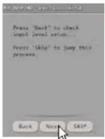
2. MASTER inputs levels calibration
Calibration is absolutely required to adapt the bit One HD inputs sensitivity to the signal coming from the source.
- Press BACK to go back to the previous step.
Press NEXT to go ahead with the inputs calibration.
Press SKIP to bypass the inputs calibration procedure.
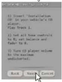
Follow the instructions listed below:
- Insert the supplied CD:
- insert the "Setup CD" if the head unit in use is an AUDIO CD Player
- insert the "TEST SIGNAL DVD" if the head unit in use is a Dolby Digital (AC3) "Audio Car Theatre 5.1" featuring analog outputs, or an analog audio system featuring a central channel.
- Play track 1 (press Play);
- Set all tone controls to zero (0);
- Set balance and fader to center (0);
- Adjust the head unit volume to the maximum undistorted output level.
Press BACK to go back to the previous step.
Press NEXT to go ahead with the setup procedure.
Press CANCEL to exit the program.
Remark: the calibration is essential to adapt the bit One HD sensitivity to the signal coming from the source.
2
WARNING: the head unit level must be elevated to the maximum undistorted level. If the head-unit level can not be tested in advance, bring the volume adjustment to approximately 80% of its maximum excursion. If the head-unit output level is set at a lower level the bit One HD will produce a ground noise (hissing sound). Should such noise come from the bit One HD during reproduction, the calibration procedure will need to be repeated at higher volume.
Screen image sequence
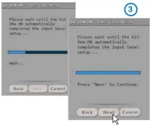
3. Automatic calibration
A progress bar and specific messages show the procedure' implementation. Once the procedure is completed, the window will show the message "Press Next to Continue".
Press BACK to go back to the previous step. Press NEXT to go ahead with the setup procedure. Press CANCEL to exit the program.
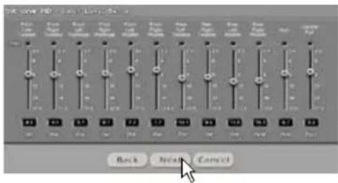
Once the procedure is completed the window will show the sensitivity levels setup according to the source interfaced with the bit One HD.
This window is active and a further manual sensitivity adjustment can be performed.
Press BACK to go back to the previous step. Press NEXT to go ahead with the setup procedure. Press CANCEL to exit the program.
ERROR MESSAGE MAY APPEAR
"Input Level too low"
Should a message informing the user that the input signal is too low appear when the inputs calibration is completed, proceed as follows:
Press BACK to go back to the previous step, check the inputs connection to the bit One HD and repeat the calibration procedure.
Press NEXT to go ahead with the setup procedure, check the inputs connection. And then proceed with the manual sensitivity calibration (see section 8.11).
Press CANCEL to exit the program.

4. Source de-equalization
Optional.
The de-equalization process performs an analysis of the electrical frequency response coming from the different channels of the OEM source, automatically applying an equalization contrary to the original one, thus generating a linear signal, much more suitable to drive high quality audio systems.
Regardless of the input channels used, the de-equalization will be performed for each functional group.

4
E.g.: even though Front Left Full and Front Right Full inputs are used, the software will perform the de-equalization also on Rear, Center and Subwoofer inputs as the processor will have to use the signals identified as Front to possibly also manage the Rear, Center and Subwoofer outputs.
Press BACK to go back to the previous step.
Press NEXT to go ahead with the setup procedure.
Press SKIP to bypass the de-equalization procedure.
Screen image sequence
5. De-equalization procedure
To perform this procedure, follow the instructions listed below:
- insert the "Setup CD" if the head unit in use is an AUDIO CD Player;
- play track 2 (press Play);
- set all tone controls to zero (0);
- set balance and fader to center (0);
- do not change the volume level previously set through the inputs level automatic calibration;
Press BACK to go back to the previous step.
Press NEXT to go ahead with the setup procedure.
Press CANCEL to exit the program.


6. De-equalization
A progress bar and specific messages show the procedure's implementation.
Once the procedure is completed, the window will show the message "Press Next to Continue".
Press BACK to go back to the previous step.
Press NEXT to go ahead with the setup procedure.
Press CANCEL to exit the program.
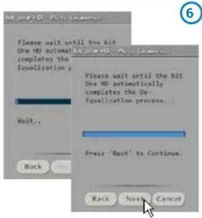
Once the procedure is completed the window will show the source equalization curves.
When activated, "De-Eq on/off" enables the de-equalization to be performed, according to the specific curve of the source interfaced with the bit One HD

Press BACK to go back to the previous step.
Press NEXT to go ahead with the setup procedure.
Press CANCEL to exit the program.
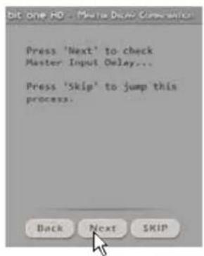
7. Master Input Delay
The presence of time delays on the inputs of the Head Unit interfaced to the bit One HD can be verified.
Press BACK to go back to the previous step.
Press NEXT to go ahead with the setup procedure.
Press SKIP to exit the program.
Follow the instructions listed below:
- play track 3 (press Play);
- set all tone controls to zero (0);
- set balance and fader to center (0);
- do not change the volume level previously set through the inputs level automatic calibration;
Press BACK to go back to the previous step.
Press NEXT to go ahead with the setup procedure.
Press CANCEL to exit the program
A progress bar and specific messages show the procedure's implementation.
Once the procedure is completed, the window will show the message:
A) Master Delay compensation is not necessary: the source has no pre-set time delays;
Press BACK to go back to the previous step.
Press NEXT to go ahead with the setup procedure.
Press CANCEL to exit the program.
B) Master Delay compensation is necessary: the source has pre-set time delays. Tick the ENABLE box if you wish to align the time delays to 0 in the system setup.
Press BACK to go back to the previous step.
Press NEXT to go ahead with the setup procedure.
Press CANCEL to exit the program
7
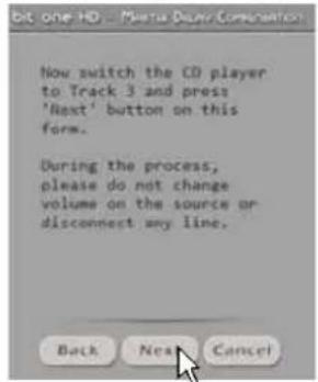


8. Auto Input Switch
The automatic volume control for the auxiliary source (Aux - Optical 1/2) can be activated through the Head Unit volume control, if it is provided with an AUX input (see section. 5.4.3, 5.6.1; 8.3.5).
Press BACK to go back to the previous step.
Press NEXT to go ahead with the setup procedure.
Press SKIP to bypass the procedure.
Follow the instructions listed below:
- connect the AUX IN inputs of the source (Head Unit) to the
bit One HD RVA input.
- select the source AUX IN input (Head Unit).
- set the source volume to the maximum undistorted level.
As previously set as per point 2 of this procedure.
Press BACK to go back to the previous step.
Press NEXT to go ahead with the setup procedure.
Press CANCEL to exit the program
When the procedure is completed :
press BACK to go back to the previous step.
press NEXT to go ahead with the setup procedure.
press CANCEL to exit the program.

8


9. Selection of the speakers available in the system
Speakers can be selected just by clicking on them. If the left tweeter, left midrange or left woofer are selected, the software provides the ability to automatically activate also the right tweeter, right midrange or right woofer. Once the software is started, this choice will affect the dedicated crossover type.
E.g.: if on the rear system only the woofers are activated, the software will only show a low-pass or band-pass filter as available.
If you want to use a coaxial system as rear channel, both tweeter and woofer need to be selected and then you need to specify that a passive crossover is connecting them, so the software will show a high-pass filter as available.
Press BACK to go back to the previous step.
Press NEXT to go ahead with the setup procedure.
Press CANCEL to exit the program.
From this point onwards a simulation of a system with the following components will be used:
- 3-way Front active
- 2-way Rear active
- 2-way center passive
- Stereo Sub
the 13 output channels of the bit One HD will be used.
8

Here it is how the bit One software shows
Screen image sequence
10. Selection of passive crossovers for speaker groups
The presence of passive crossovers managing speaker functional groups in complex systems can be provided by the user.
E.g.: the 3-way Front can be managed as:
- multi-amplified (6 output channels would be required);
- passive mid-high speakers + separately amplified woofer (4 output channels would be required);
- 3-way passive (2 output channels would be required).
While performing the setup, the software will automatically notify the return within the 8 output channel limit, the warning message will then disappear and the NEXT button will appear.
Press BACK to go back to the previous step.
Press NEXT to go ahead with the setup procedure.
Press CANCEL to exit the program.

11. Processor outputs (Ch1÷Ch13) allocation
The bit One HD features 13 output channels. On this specific step of the procedure, any signal can be assigned to each output channel.
E.g.: the outputs 1 and 2 can be assigned to the rear channels simply to avoid having to lengthen the cables going to the specific amplifier. For a matter of convenience, if the output 1 is assigned to the left woofers, the software will automatically assign the output 2 to the right woofers. If during the procedure the output 1 is assigned also to the left mid-high speakers, the software will show a warning message. Change the allocation of one of the two numbers marked in red and the software will automatically select the first available channel.
Press BACK to go back to the previous step.
Press NEXT to go ahead with the setup procedure.
Press CANCEL to exit the program.

12. Selection of the amplifiers connected through the AD Link / AC Link connection system
If the system features amplifiers provided with the AD Link digital input and you want to connect them to the system, you need to select them on this setup procedure window.
The CH1-CH8 output channels will be available on the AD LINK 1 socket, while the CH9-CH13 channels will be available on the AD LINK 2 socket.
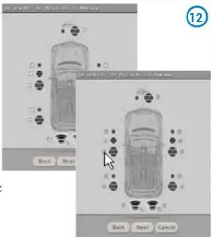
Remark: remember to assign the corresponding Amp ID to the specific amplifier. The bit One HD will automatically recognize the identified amplifier.
Screen image sequence
13. System configuration successfully completed
Stop playing the Test track, remove the supplied Setup CD from the head unit CD player and then press OK.

13
7.5 MASTER OPTICAL 1 INPUT SELECTION
1. Auto Input Switch
The automatic volume control for the auxiliary source (Aux - Optical 1) can be activated through the Head Unit volume control, if it is provided with an AUX input (see section 5.4.3 - 5.6.1)
Press BACK to go back to the previous step.
Press NEXT to go ahead with the setup procedure
Press SKIP to bypass the procedure.

①
Follow the instructions listed below:
- connect the AUX IN inputs of the source (Head Unit) to the bit One HD RVA input.
- select the source AUX IN input (Head Unit).
- set the source volume to the maximum undistorted level.
Press BACK to go back to the previous step.
Press NEXT to go ahead with the setup procedure.
Press CANCEL to exit the program.
-
When the procedure is completed:
press BACK to go back to the previous step.
press NEXT to go ahead with the setup procedure.
press CANCEL to exit the program.
Screen image sequence
2. Selection of the speakers available in the system

Speakers can be selected just by clicking on them. If the left tweeter, left midrange or left woofer are selected, the software provides the ability to automatically activate also the right tweeter, right midrange or right woofer. Once the software is started, this choice will affect the dedicated crossover type.
E.g.: if on the rear system only the woofers are activated, the software will only show a low-pass or band-pass filter as available. If you want to use a coaxial system as rear channel, both tweeter and woofer need to be selected and then you need to specify that a passive crossover is connecting them, so the software will show a high-pass filter as available.
Press BACK to go back to the previous step.
Press NEXT to go ahead with the setup procedure.
Press CANCEL to exit the program.
From this point onwards a simulation of a system with the following components will be used:
- 3-way Front active;
- 2-way Rear active;
- 2-way center passive;
- Stereo Sub;
the 13 output channels of the bit One HD will be used.

Here it is how the bit One HD software shows the speakers selected in the system
3. Selection of passive crossovers for speaker groups
The presence of passive crossovers managing speaker functional groups in complex systems can be provided by the user.
E.g.: the 3-way Front can be managed as:
- multi-amplified (6 output channels would be required);
- passive mid-high speakers + separately amplified woofer (4 output channels would be required);
- 3-way passive (2 output channels would be required).
While performing the setup, the software will automatically notify the return within the 8 output channel limit, the warning message will then disappear and the NEXT button will appear.
Press BACK to go back to the previous step.
Press NEXT to go ahead with the setup procedure.
Press CANCEL to exit the program.

4. Processor outputs (Ch1÷Ch13) allocation
The bit One HD features 13 output channels. On this specific step of the procedure, any signal can be assigned to each output channel.
E.g.: the outputs 1 and 2 can be assigned to the rear channels simply to avoid having to lengthen the cables going to the specific amplifier.
For a matter of convenience, if the output 1 is assigned to the left woofers, the software will automatically assign the output 2 to the right woofers. If during the procedure the output 1 is assigned also to the left mid-high speakers, the software will show a warning message. Change the allocation of one of the two numbers marked in red and the software will automatically select the first available channel.
Press BACK to go back to the previous step.
Press NEXT to go ahead with the setup procedure
Press CANCEL to exit the program.

Screen image sequence
5. Selection of the amplifiers connected through the AD Link / AC Link connection system
If the system features amplifiers provided with the AD Link digital input and you want to connect them to the system, you need to select them on this setup procedure window. The CH1-CH8 output channels will be available on the AD LINK 1 socket, while the CH9-CH13 channels will be available on the AD LINK 2 socket.

Remark: remember to assign the corresponding Amp ID to the specific amplifier. The bit One HD will automatically recognize the identified amplifier.
6. System configuration successfully completed
Stop playing the Test track, remove the supplied Setup CD from the head unit CD player and then press OK.

6
8. bit One HD INSTALLATION GUIDE USING A PC
Software Start Up
The software transfers the settings selected during the guided procedure to the processor main memory.
For the first connection of the bit One HD to a PC, we recommend to FINALIZE the bit One HD, to avoid losing the data stored when performing the auto-setup process (see section 8.2.3).
At this stage the bit One HD is provided with the appropriate basic setup. In the following chapters the features allowing acoustic tuning of the system will be detailed.

WARNING: We recommend that you do not modify the settings of your bit One HD to explore its different features. Take your time to get familiar with the possibilities this software offers. The settings applied to the bit One HD have immediate effect on the signal. Should these settings not be performed with the due attention, they may cause damage to the system speakers.
If you decide to leave the amplifiers connected to the bit One HD, remember to perform the adjustments keeping the general volume at a level which does not damage the speakers in your system.
8.1 FEATURES
The following pages describe the bit One HD features that can be managed through the software.

7
8.2 MAIN MENU: "FILE" 1
Selecting the "File" tab a drop-down menu shows up listing the entries as shown in the image to the right of this page.
![1 Load Setup... 2 Save Setup... 3 FINALIZE to bit One HD 4 Synchronize 5 Check for Update 6 Check for Update on Startup 7 Register Product 8 Update Firmware 9 Reset Default Answer 10 Restore Factory Defaults 11 Restore Window Size [Alt+F10] 12 Help Online 13 Credits 14 Exit](/content/2026/05/949620/images/a6d66d7543db55d63bd6bfb5a6f127d6475cc6a1d19451c79bffd328275458dd.jpg)
1 Load Setup: by selecting this entry, the bit One HD entire setup is loaded from a previously saved file (EX. "BitOnehdConfig1.bhd"). This feature is available both in TARGET and OFFLINE mode. In TARGET mode this function provides the ability to load again all the settings that have been previously saved. It is useful if you want to resume all the settings you have previously selected to install another bit One HD with the same adjustments, in order to test different acoustic settings.

In OFFLINE mode this function allows the user to view the features previously saved in order to consult them.
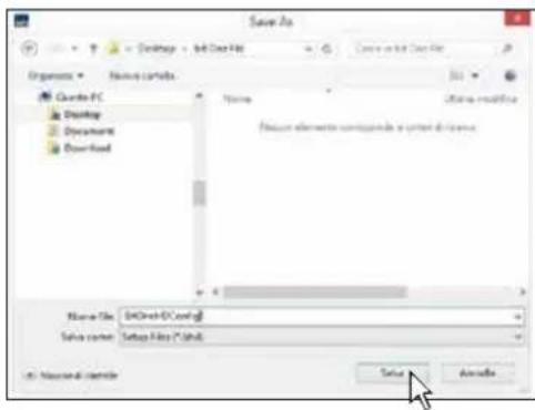
2 Save Setup: it enables the storage of the entire bit One HD configuration in a file (EX. BitOnehdConfig1.bhd") that you can subsequently load into the bit One HD through the Load Setup function. This feature is available both in TARGET and in OFFLINE mode.
3 FINALIZE to bit One HD: this function enables the loading of all the parameters selected while configuring the bit One HD microprocessor internal memory, allowing it to work without being connected to a PC. When selecting the Finalize to bit One HD function, the software notifies that the data previously saved in the bit One HD will be overwritten.
- Select YES to load the data saved in the bit One HD, overwriting the previously saved data, if any.
- Select NO to interrupt the process.
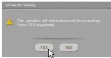

WARNING: before disconnecting the bit One HD from the PC or each time that you exit the PC software after modifying the system configuration, always run the Finalize to bit One HD procedure. If you do not follow these instructions all the data entered will be lost.
4 Synchronize, PC -> bit One HD or PC <- bit One HD:
these functions synchronize the PC with the bit One HD. If a dialog box as the one to the right of this page shows up, it means that for some reason communication between the PC and the bit One HD has been interrupted. To restore the communication select:
- PC -> bit One HD. The PC loads the settings selected so far in the bit One HD.
- PC <- bit One HD. The PC loads the settings previously stored in the bit One HD on the PC software.
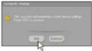

WARNING: this operation can not guarantee that the data are always retrieved.
If the operation is not successful:
- exit the bit One HD software.
- turn the bit One HD off.
- turn the bit One HD on.
- launch the bit One HD software again.
By performing these actions, synchronization will be restored but the selected settings will be lost.
5 Check for updates: it enables the connection to the website "www.audisonbitdrive.eu" to check if any software / firmware updates for the bit One HD are available (see section 9.3). To perform this operation, your PC has to be connected to the internet.
6 Check for Updates on Startup: when enabled, the software automatically checks the availability of new Firmware/PC software updates each time the program is started. (see section 9.3).
7 Register product: this function requires an internet connection and opens the default browser to the page for registering the product and creating a personal account in the "bit Drive" portal. This operation only needs to be performed once; then you can access your account through the Account Login. (see section 9.3).
8 Update Firmware: function to update the bit One HD firmware (see section 9.3).
9 Reset Default Answer: it restores the display of the warning messages if they have been disabled by ticking "Don't show me again".

10Restore Factory Defaults: it entirely resets the bit One HD back to its default settings, cancelling all the data previously saved in the bit One HD (see section 8.2.3).
WARNING: during this procedure the bit One HD RCA / AD LINK - AC LINK outputs to the amplifiers should be disconnected.


11 Restore Window Size: this functions performs the re-sizing of the PC software window to the default dimension. Re-sizing can also be performed through the PC keyboard, using ALT+F10 keys.
12 Help Online: this function requires an internet connection. By activating this function and moving the mouse pointer to the various sections of the graphic interface for the PC software, the concerned area will be highlighted in red. By clicking on the red area, a link will activate, opening up the default browser, displaying the paragraph of the manual related to that specific area. The manual will be displayed in the language selected in CONFIG->Language.
13 Credits: it shows the information about the bit One HD software in use.
14 Exit: it exits the PC Software.
8.3 MAIN MENU: "CONFIG"
2
Selecting the "Config" tab, a drop-down menu appears listing the entries as shown in the image:
1 I/O Configuration Wizard: it provides the ability to perform a new auto-setup, providing the bit One HD with the conditions required to run this operation (see section 7.2).
2 Input Configuration Wizard: this function allows for the calibration of the bit One HD inputs only, without modifying the outputs configuration (see section 7.2).
3 Auxiliary Inputs: it provides the ability to enable or disable auxiliary sources which have been or have not been selected while performing the setup (see section 7.2.1), without repeating the calibration procedure.
4 Working Mode: the software is provided with two working modes: Standard and Expert, acting on the crossover filter section.
The Standard mode features restrictions easing the use of the software (see section 8.7).
The Expert mode does not feature any restrictions in the functions for the use of the software (see section 8.7).
We suggest to try and use the software in Expert mode; should it be too difficult, change to Standard mode.


WARNING: when you change from one mode to the other, the crossover filters parameters are restored back to the default ones.
5 Auto Input Switch: this function provides the ability to select an auxiliary input of the bit One HD: Optical 1, Optical 2, AUX and possibly control the volume from an external source provided with an AUX input. To use this function it is necessary to perform the calibration during the I/O Configuration Wizard phase (see section 8.3.1) and connect the bit One HD RVA input, as described in Sections 5.4.3 e 5.6.1.

Functions Description:
A. Source: function to enable the automatic selection of one of the three external sources available; AUX, Optical 1, Optical 2. Select the source to activate enabling the AUX input of the system source (Head Unit).
B. Threshold: function to set the auxiliary input signal minimum threshold previously selected, to activate it. The operation levels range from 0 dB to -96 dB.
C. Auto Gain: function to automatically set the threshold level to activate the auxiliary source.
Advanced menu.
Selecting the box as shown in the picture to the side the advanced setup menu is activated, essential when adjusting the "Auto Input Switch" function.
A. Attack: function to set the starting time for the auxiliary input to activate The operation levels range from 13 ms to 680 ms.
B. Release: function to set the turn off time of the auxiliary input activated. The operation levels range from 13 ms to 680 ms
C. Freq Tone: function to choose the selection tone of the Head Unit AUX input. It is set to 18 KHz by default, but it can be changed according to the Head Unit performance, from a minimum of 14 KHz to a maximum of 22KHz.
This frequency is not audible as it is concealed by the processor, and works as a control for the Master volume and for the selection of an auxiliary input of the bit One HD. The frequency selection must be performed choosing the highest possible value, to make sure the tuning operation is working properly. Should any malfunctioning occur when switching the inputs or tuning the volume, select the lowest available value, in order to reach a good functional compromise.
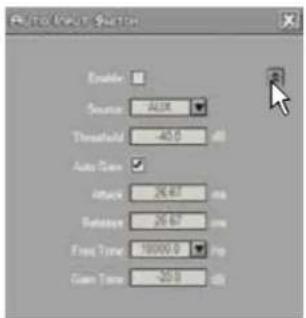
D. Gain Tone: function to set the "Freq Tone" level for the bit One HD auxiliary input switch. The Gain Tone default value is set according to a value calculated during the I/O Configuration Wizard phase. The operation levels range from 0 dB to -96 dB.
Note: (see section 5.6.1)
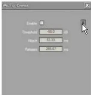
6 Auto Chimes: activate this function by ticking the Enable box to switch to the main Master input each time a "Gong Signal" coming from the car should be heard.
Functions Description:
A. Threshold: function to set the minimum threshold level of the "Gong Signal" coming from the Head Unit Master input. The operation levels range from 0 dB to -96 dB.
Advanced menu
Selecting the box as shown in the picture to the side the advanced setup menu is activated, essential when adjusting the "Auto Chimes" function.
A. Attack: function to set the starting time for the auxiliary input to activate The operation levels range from 13 ms to 680 ms.
B. Release: function to set the turn off time of the auxiliary input activated. The operation levels range from 13 ms to 680 ms.

7 Power-On From HiLev: select this entry to activate the bit One HD turn on using a high level signal (ART, Auto Remote Turn On), available on the CH1 and CH2 channels.
8 Master Delay Compensation: select this entry to enable/disable the Head Unit time delays compensation. This function is available if during the "I/O Configuration Wizard" phase the "Master Input Delay" procedure has been performed (see section 8.3.7).
9 Startup/Shutdown Delays: function to modify the bit One HD startup and shutdown delays.
- StartUp Time: delay between the device startup and the output audio turn on. Each amplifier, when starting up, has its own delay before becoming operative. By setting the Startup Time to a value equal to or higher than the longest of these delays a synchronized startup of the audio of the entire system can be achieved.
- Shutdown time: delay between the turn off/deactivation of the REMOTE OUT signal to the amplifiers and the bit One HD shutdown. Acting on this parameter is not generally essential but it could useful to decrease it when amplifiers in the system produce a "Bump" while shutting down.


10 Language: to change the language select your preference among the ones available on the menu.
8.4 MEMORY 3
The bit One HD manages the system setup working on Preset A by default; however, it also offers the possibility to store and recall eight Presets (A, B, C, D, E, F, G, H).
Pressing the MEMORY button on the main menu you can access the different functions you can perform on the featured presets.
The following functions are available:
- Load All Presets: it loads all the memories (A/B/C/D/E/F/G/H) from a file previously saved (.prs format);
- Save All Presets: it saves all the memories (A/B/C/D/E/F/G/H) in a file that can be recalled (.prs format);
- Load Current Preset: it loads a memory previously saved (.pro format) by placing it on the memory you are operating on;
-Save Current Preset: it saves the memory you are operating on in a file that can be recalled (.pro format); - Copy Preset From: it provides the ability to copy the content of one memory into another memory;
- Current Preset Default: it restores the crossover and equalization default values, that would be suggested at the end of the set up procedure;
- Enable Memory Overall: it enables the Overall function which recalls a memory previously saved (see following point), optimized for a perfect listening from all positions within the car compartment. This function can be activated through the terminal, setting the Overall Sel cable to +12V (see section 8.3.4);
- Select Memory Overall: it configures an existing memory as "Overall". If an existing memory has been configured with time delays, these will be reset and the Car Central will be set up as the listening position (see section 8.5). At a later stage, the settings related to this "Overall" memory can be modified.
The following data will be stored into the presets:
- the filter settings for each channel;
- the time delay settings for each channel;
- the equalization settings for each output channel;
- the Main EQ settings (see section 8.9.2);
- the Dynamic EQ settings/activation (see section 8.12.3);
- the Bass Boost settings/activation (see section 8.12.4);
- the output levels of each channel;
- listening points markers.
We recommend that you copy the parameters entered in the preset you are using into the presets that are not being used. The presets can be recalled through the DRC MP. If some presets are not stored, they will store the Default settings.


8.5 SELECT A CHANNEL 4
This window is active. You can click on the speaker or on the speaker system to manage each single channel that, once selected, will be highlighted.
If you keep the CTRL key pressed and click on another channel, this other channel will be selected and highlighted as well.
LISTENING POSITION VISUAL INDICATOR
This window includes the position indicator (highlighted in green). Four positions are pre-set: driver, passenger, front central (passenger driver) and rear central.
The indication acts only and exclusively as reference, allowing to view the listening point optimized with the digital delay automated calculation.
If delays are set according to the "driver" position and then you want to optimize the system also for the "passenger" position, you need to set the distances again through the specific menu, as the system does not update them automatically.
If used together with the pre-sets, it is useful to create different setups according to the different listening positions.

8.6 CHANNEL MAP 5
This window displays the names given to the eight output channels of the bit One HD.
This window is active. You can click on it to manage each channel which, once selected, will be highlighted.
The software will anyhow only allow you to work on one single channel and will display the word EDIT in red next to the channel you can operate on.
This selection ensures that all highlighted channels responses are displayed (see section 8.5).

Remark: the channels highlighted in green are dedicated to the AD LINK 1 and AD LINK 2 digital outputs
Output channels multiple selection.
If you keep the CTRL key pressed and click on another channel, this other channel will be selected and highlighted as well. Multiple channels can be selected by ticking the "Multi Sel" box. Multiple selection is only allowed for functional groups, except for the Subwoofer that can be selected with any group.
To act on another channel keeping your selection, click on the right hand of the desired channel, where the EDIT column is.
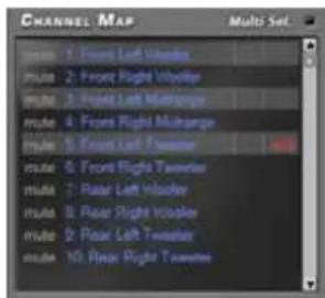
E.g.: front Left Mid-Hi with Front Left Woofer with Subwoofer, but not with Rear Left Full or Center Full. If you want to check the Rear+Subwoofer system electrical response you have to de-select the Front system.
When multiple channels are selected the display will show the electrical response for all channels with a blue curve/line, highlighting the "active" channel in red and the other channels in grey.
You can also select a channel as shown in the diagram in chapter 8.5.

8.7 FILTER SETTINGS 6
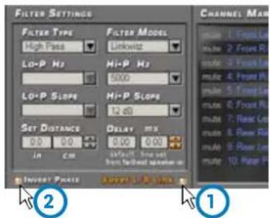
The bit One HD manages 13 crossovers, one for each output channel. Each filter allows the setting of the parameters related to the channel highlighted on the Channel Map.
- Xover L/R Link: when activated, the modifications applied to one of the channels (right or left) will automatically be applied also to the other one. To activate it click on the blue flashing light.
- Invert Phase: it provides the ability to invert the phase of the channel under examination by 180°. It can be activated by selecting the green flashing light.
This function can be useful to solve alignment problems among the different filtered channels.
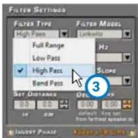
- Filter Type: it enables the selection of the different types of filters that can be assigned to channels.
Full Range
Low Pass
High Pass
Band Pass
In STANDARD mode:
according to the speaker system selected during the setup, the filter type suitable for the used speaker will be available.
E.g.: for the Front Woofer only Low Pass or Band Pass will be available. For the Front Mid-Hi only High Pass and Band Pass will be available, etc.
In EXPERT mode:
any speaker system selected features any filter type available.
WARNING: in this case pay utmost attention to the filter adjustment. Speakers have mechanical limits which must not be exceeded and could lead to damage to the components.
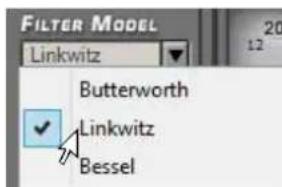
- Filter Model: it enables the selection of the applicable type of filter
Butterworth (default)
Linkwitz
Bessel
When launching the software, the bit One HD offers Butterworth as standard filter model. If you change it into Linkwitz or Bessel, the change will be applied only to the channel (mono) or channels (stereo - Xover Link enabled) you are working with.
STANDARD MODE
| Full Range | Low Pass | High Pass | Band Pass | |
| Tweeter | X | X | ||
| Midrange | X | |||
| Woofer | X | X | ||
| Mid-Hi | X | X | ||
| Subwoofer | X | X | ||
| Full | XXX |
EXPERT MODE
| Full Range | Low Pass | High Pass | Band Pass | |
| Tweeter | × × × × | |||
| Midrange | × × × × | |||
| Woofer | × × × × | |||
| Mid-Hi | × × × × | |||
| Subwoofer | × × × × | |||
| Full | × × × × |
5. Cut-off frequencies:
- Hi-P Hz 10 ÷ 20000; filter High-Pass
- Lo-P Hz 10 ÷ 20000: filter Low-Pass
The cut-off frequency can be selected by:
- clicking on the corresponding drop-down menu, selecting the frequency range and the value;
- clicking on the corresponding drop-down menu, then moving from value to value with the arrows
controls (up / down) on the PC keyboard; - clicking on the corresponding drop-down menu and then moving from value to value with the use of a mouse featuring a rotating finger wheel
- Click on the cut-off frequency (Lo-P, Hi-P) section and edit the required value through the keyboard.
In STANDARD mode the crossing frequency among speakers of the same front is bound.
It is however free among different fronts.
E.g.: if you change the Front Woofer low-pass cut-off frequency, also the Front Mid-Hi hi-pass cut-off frequency will automatically change. If instead you change the Subwoofer low-pass cut-off frequency, the Front Woofer hi-pass cut-off frequency will not change.
In EXPERT mode the crossing frequency among speakers of the same front is free, meaning that open cuts can be created.


STANDARD mode 500 Hz crossover frequency

EXPERT mode crossover frequency :
- Low Pass 750 Hz
- High Pass 2000 Hz
- Low Pass 750 Hz
- High Pass 2000 Hz
6. Filter slope
- Hi-P Slope
6/12/18/24/30/36/42/48 dB/Oct. (Butterworth)
12/24/36/48 dB/Oct. (Linkwitz)
6/12/18/24/30/36/dB/Oct. (Bessel)
- Lo-P Slope
6/12/18/24/30/36/42/48 dB/Oct. (Butterworth)
12/24/36/48 dB/Oct. (Linkwitz)
6/12/18/24/30/36/dB/Oct. (Bessel)
When starting up the software, the bit One HD offers Butterworth with 12 dB/oct slope as default slope. By changing the slope, the change will be applied only to the channel you are working on.
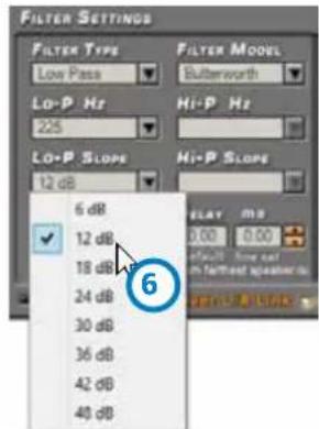
E.g.: if you are adjusting the Front Woofer, the change will affect only that channel (right and left, if linked). If you selected Band Pass as filter type, the slope will be applied to both hi-pass and low-pass. With the Band Pass filter type the filter slopes can be unbound.
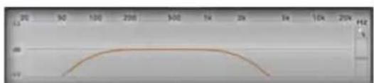
line
| X-Axis | Y-Axis | |---|---| | 0 | 0 | | 10 | 10 | | 20 | 20 | | 30 | 30 | | 40 | 40 | | 50 | 50 | | 60 | 60 | | 70 | 70 | | 80 | 80 | | 90 | 90 | | 100 | 100 | | 110 | 110 | | 120 | 120 | | 130 | 130 | | 140 | 140 | | 150 | 150 | | 160 | 160 | | 170 | 170 | | 180 | 180 | | 190 | 190 | | 200 | 200 |line
| X-Axis (Value) | Y-Axis (Percentage) | |---|---| | 20 | 10 | | 50 | 20 | | 100 | 30 | | 200 | 40 | | 300 | 45 | | 1k | 45 | | 2k | 45 | | 5k | 30 | | 10k | 15 | | 20k | 5 |2000 Hz @ 48dB Oct. Low-pass

Frequenza di crossover 80 - 2000 Hz @ 48 dB/Oct. Hi-pass 2000 Hz @ 6dB Oct. Low-pass
8.8 SET DISTANCE AND DELAY 7
This setting is based on an automatic system allowing to calculate the time the speaker sound takes to get to the listener's ear (Fig.1).
Preliminary remarks
Sound moves through the air at a speed of 343 mt/sec (1.125 ft/sec) and at the temperature of 20°C (68°F). If you know the distance from the sound emission point, you can then calculate the time sound takes to get to the listener's ear. If you set the distances of the different speakers in your system, the bit One HD automatic system will change them into time (ms - milliseconds). It does not assign the delay (0.0 ms) to the farthest speaker (usually the Subwoofer) while it assigns progressively growing delays as much as the other speakers position gets closer to the listening point, in order for all the emission points to reach the listening point at the same time.
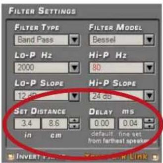
Fig.1
SET DISTANCE
It enables the setting of the distance between a specific speaker and the listening point. Choose cm (centimetres) or in (inches).
DELAY ms/default
It displays the time in ms (milliseconds) calculated according to the distance.
DELAY ms/fine set
The calculation system of the bit One HD time delays also allows for a manual fine-adjustment.
Preliminary remarks
Fine set and Phase Delay
The delay assignment according to the distance calculation is theoretical. That is, small variations need to be applied due to small errors in distance measurement, due to the back-wave reflections inside the car compartment and, mainly, due to the speaker phase problem. Two speakers reproducing two areas of frequency one close to the other (ex. Woofer and Midrange), in their crossing area will simultaneously reproduce, at attenuated level, the same frequencies. Due to the different nature of the speakers, they will show a difference in phase that, for a short frequency interval, works like a time delay. By acting on the "fine set" you can partly also correct problems of Phase Delay.
By acting on the "fine set" you can change the automatically set time delay. The delay that is varied adds up to (+ x.xx) or is deducted from (- x.xx) the value of the delay shown in the "Delay / default" window, which does not change the assigned value which is the one automatically assigned. Assigning a positive value (+ x.xx) with the "fine delay" means increasing the delay of that speaker and therefore moving it away from the listening point. Likewise, assigning a negative value (- x.xx) means decreasing the speaker's delay and therefore moving it closer to the listening point. (Fig.1)
To see how much the "fine set" has been manually changed both values are displayed. To see the resulting delay value, actually applied to the output, you have to calculate the algebraic sum of the value shown in the "DELAY / default" and "DELAY / fine set" boxes. The negative value (decreasing the delay) can not be assigned to the farthest speaker; it can only be assigned to the other speakers as they are all already delayed compared to the farthest one. If you try and give a negative value to the farthest speaker, an alert message will be displayed (Fig.2). By acting on "fine set", the word "fds" will light up on the corresponding channel of the "Channel Map" (Fig.3).

Fig.2
Example of time delay setting (Fig.4):
- choose the system listening point. To identify the listening point, choose an ideal point located at the center of the listener's (driver or passenger) head. For the front central and rear central points choose an intermediate point between the two listeners.
- measure the distance between each loudspeaker or group of loudspeakers and the listening point in a straight line ("as the crow flies") (Fig. 4). For each loudspeaker choose the center of the mobile membrane as the emission point. For the groups of loudspeakers choose an intermediate point between them. Afterwards, fine-tuning can be performed by selecting the Fine Set function.
- select the channel related to the loudspeaker under exam on the Channel Map and enter the respective distance value on the Set Distance box from the Filter Settings menu (Fig. 5).
- repeat step 3 for each channel.
- perform all the time delays settings, start the music reproduction and select the Fine Set box. If you move the values to positive or negative (except for the subwoofer in Fig.6 as it is the farthest speaker), you can find the best time alignment that will ensure a correct acoustic scene.
The fine set tuning can be managed through the multiple selection of the audio system emission front (Ie. Front Left Tweeter + Front Left Midrange + Front Left Woofer). Select the front (Left or Right) channels keeping the CTRL key pressed with the mouse pointer, then proceed to the fine set tuning.
It is advisable to listen to different types of musical tracks (percussions, melodic etc.) for a much more correct evaluation of the different musical instruments coherency (space stability).
- once the time alignment procedure is completed, you can operate on the output equalizer (Master). You can refer to optimize the system response in accordance with the level alignment to the different frequencies.
Remark: the measurements for the above operations can also be taken by using a spectrum analyzer featuring an appropriate microphone. The result must be assessed with final refining listening tests.

Fig.3
Real distances measured from the listening point.

Fig.4

Fig.5
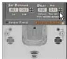
Fig.6
WARNING: if, once you have set the distances according to the
Driver" listening point you click on the "passenger" listening point, the bit One HD will not re-calculate the delays according to the new reference point because the buttons available in the SELECT A CHANNEL diagram are merely descriptive and their only purpose is to remind you that you have set the delays for that listening point!
8.9 EQ SETTINGS
8
The bit One HD software provides a series of equalizers to be managed on screen which, with extreme versatility, provide for an optimal calibration of the audio system. The user can operate on the equalization of the Master or AUX analog inputs by choosing the "Input EQ" option, on the whole system equalization by choosing the "Main EQ" option and on the bit One HD single output channels equalization by choosing the "Output EQ" option.

- Input EQ: tick the "Input EQ" box and the equalization curve for the bit One HD active input will be displayed (see section 9.6). The calibration for the selected analog inputs can be performed with a 5 poles ± 12dB equalizer.


- Main EQ: it displays the bit One HD general output equalization curve. An equalization for all the system's outputs can be set up with a 5 poles ±12dB equalizer.

- Output EQ: it displays the equalization curve of the bit One HD selected channel output. A calibration of the input can be performed with an equalizer featuring 11 poles of which 9 parametric poles and two Shielding (LP HP).
The equalizer works with functional groups:
- an equalizer for the Front Left Channels;
- an equalizer for the Front Right Channels;
- an equalizer for the Rear Left Channels;
- an equalizer for the Rear Right Channels;
- an equalizer for the Center;
- an equalizer for the Subwoofer.
To change the equalizer parameters in order to set an equalization curve, select the channel to be equalized from the "Channel Map" menu, enable the parametric pole to operate on, place the mouse pointer on the section to be set up and shape the curves with the mouse left click (green curve).
To change the "Q" factor of the selected equalization section, a mouse featuring a rotating finger wheel can be used.
To operate on the parametric equalizer the setup window (as shown in the image to the side) can also be used, providing a more detailed setting on the following parameters:
- operating frequency pole 20÷20 kHz.
- parametric pole gain ±12dB.
- quality factor Q 1÷10.


The equalizer features specific functions to ease the calibration.

During the equalizer calibration the systems shows the modifications applied to the electric signal transferred to the speakers by the amplifiers in real time.
The actual audio signal reproduced by the system depends on the type of speakers used and their position. To analyze the acoustic response it is essential to use a spectrum analyzer connected to the microphone. Otherwise you can rely on your experience with listening and proceed to a fine tuning according to this.
- Flat: when selected, it restores all sliders of the parametric equalizer to 0 dB position
2.LinkL/R: when activated, it applies the equalization curve to the right and the left channel simultaneously
3.L->R R->L: this function is active when "Link L/R" is disabled. By Clicking on one of the two buttons the equalization curve can be transferred from the Left to the Right channel and vice versa - Xover: by selecting the box (red curve), it allows the user to see the electric response under filtering (XOVER).

line
| X-Axis | Series 1 | Series 2 | |---|---|---| | 20 | 60 | 60 | | 30 | 60 | 60 | | 100 | 60 | 60 | | 200 | 60 | 60 | | 300 | 60 | 60 | | 400 | 60 | 60 | | 1K | 60 | 60 | | 2K | 60 | 60 | | 5K | 60 | 60 | | 15K | 60 | 60 | | 25K | 60 | 60 |5.EQ: by selecting the box (yellow curve), it allows the user to see the electric response under equalization

line
| X-Axis Label | Y-Axis Value | |---|---| | 20 | 40 | | 80 | 35 | | 100 | 30 | | 200 | 25 | | 600 | 20 | | 14 | 15 | | 24 | 10 | | 64 | 5 | | 104 | 3 | | 204 | 2 | The chart displays a single data series with no explicit title or legend labels. The x-axis is labeled 'H' and the y-axis is labeled 'M'. The data points are marked with black dots and connected by lines, indicating possible clustering or comparison points. No trend or correlation can be inferred due to absence of specific data series.6.SUM: by selecting the box (purple curve), it allows the user to see the sum of the electric response and the crossover
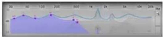
line
| Time | Value | |---|---| | 20 | 48 | | 50 | 52 | | 100 | 49 | | 200 | 53 | | 500 | 47 | | 1k | 51 | | 2k | 60 | | 5k | 48 | | 10k | 47 | | 20k | 46 |7.EQOff: when activated, it enables the equalizer de-activation.
Remark: in order to see the equalization curve set up more clearly, the vertical scale (dB) can be increased or decreased by moving the slider located to the right of the diagram displaying the equalization curve. By default the diagram is displayed at ±12dB.


line
| Time (s) | Frequency (Hz) | | :--- | :--- | | 20 | 18 | | 30 | 16 | | 50 | 17 | | 100 | 20 | | 200 | 22 | | 300 | 24 | | 500 | 26 | | 14 | 10 | | 24 | 28 | | 34 | 30 | | 54 | 32 | | 104 | 34 | | 204 | 36 | The chart displays a single line representing frequency over time in seconds. The x-axis is labeled 'Time (s)' and the y-axis is labeled 'Frequency (Hz)'. The data series is annotated with values such as '18' and '28'.Example of diagram displayed with magnifier ± 3dB function

line
| Frequency (Hz) | Label | |---|---| | 20 | 1 | | 50 | 1 | | 100 | 1 | | 300 | 1 | | 600 | 1 | | 1 Hz | 1 | | 2 Hz | 1 | | 5 Hz | 1 | | 10 Hz | 1 | | 200 Hz | 1 |Example of diagram displayed with magnifier + 24dB function
8.10 OUTPUT LEVEL 9
This section shows the settings of the output levels of the bit One HD channels as displayed by the software.

Following please note the description of each of the functions marked with numbers in the image above.
1 When "Clip" lights up in red, it means clipping is occurring on the output channel. When this occurs, you will just have to decrease the output level of the corresponding channel or decrease the equalization previously set up. If the "Limiter" function has been applied to the clip the led light will be orange.
2 By acting on one of the sliders belonging to the output channels, the output level (- 40 ÷ 0 dB) for each channel can be adjusted
3 This area of the screen shows the output level of each single channel (- 40 ÷ 0 dB), compared to the slider position of the output channels
4 By selecting "Link", all the bit One HD output levels can be adjusted simultaneously. By selecting "Link" again the function will be disabled.
5 By selecting "Solo" the output levels will be muted except the active one. By selecting "Solo" again this function will be disabled.
6 The selection of the "Mute" button provides the ability to mute the corresponding output channels. By selecting "Mute" again, the mute function will be disabled.
7 By acting on the "Master Volume" function, you can adjust the system general volume (-60 ÷ 0 dB).
8 The "Subwoofer Level" function allows for the subwoofer output level adjustments (-12 ÷ 0 dB), when the system features a subwoofer.
9 The "Limiter" function enables the limiter on bit One HD output level. This function is essential to avoid the occurrence of temporary clipping, causing the outputs saturation. By selecting "Limiter" again, the function will be disabled.
Remark: if the installation includes a mono Subwoofer, the sensitivity of its dedicated amplifier needs to be increased by +3 dB compared to rest of the amplifiers (see the "Amplifiers Sensitivity" diagram). This empirical method considers many aspects and will provide an improved adjustment capability of the "Subwoofer Level
Amplifiers Sensitivity (Volts)
| Front/Rear | 1 | 0 | 2.0 | 3 | 0 | 4.0 | ||
| Sub (+3 dB) | 0.7 | 1.4 | 2 | 1 | 2.8 | |||

WARNING: the output level adjustment (2) affects the system signal / noise ratio (whistle / background hiss). We recommend that you always set the bit One output at high level and the amplifiers' sensitivity at low level, so the amplifiers will be less sensitive to background noises/hisses. An excessive output level causes the clipping led lights to turn on (1), especially if equalizations with high gain are applied. Therefore we recommend that you proceed as follows.
a) Adjust the amplifiers sensitivity level to the minimum value (3-4V RMS).
b) Balance the emission level of the system channels by moving the sliders (2) paying attention to maintain a centered mid level at around -20 dB. Turn the output volume to an acceptable listening volume level.
c) Set the desired output equalizations (see section 8.9).
d) Insert a CD playing a highly dynamic track.
e) Select the "Link" function (5), move the slider and increase the output channels level until one of the "clipping" led lights turns on (1); move the slider back of at least 2-3 dB (check the value on one of the displays (3)).
f) Increase the "Master Volume" (6) up to the maximum undistorted level taking it close to "0" dB.
g) In case the signal is highly distorted with the "Master Volume" at "0" dB, the output levels (2) will need to be decreased. If, on the contrary, no distortion occurs, the amplifiers' sensitivity will have to be increased until the first distortion symptoms appear: by doing this, you will make the most of all the available power.
Remark: this procedure leads the user to calibrate the system at "zero dB undistorted". This is not always the best solution, since, if you listen to a track that has been recorded at a lower level or with lower dynamics than the track used for the setup, a loss in dynamics may occur. So a good compromise needs to be found, depending on the listener preferences.
8.11 SELECT INPUT 10
The "Selected Input" window will display the active source during the connection with the PC. Auxiliary sources can be added or removed entering the Config->Auxiliary Inputs menu and selecting the desired source (see section 8.3.3). Once you will have disconnected from the PC, the bit One H D input source can be selected via DRC MP
Sensitivity: to perform the setting/display of the analog inputs. Click on the icon for the input setup.
To perform the sensitivity adjustment, refer to section 8 of this user manual.

8.12 SETUP 11
-
Auto EQ: function unavailable for this Software version.
-
Master De-EQ: by entering this section the Head Unit specific equalization curve evolution is displayed (see section 7.3.6, 7.4.6).
- The selection of De-Eq on/off enables the activation/de-activation of the de-equalization applied to the Head Unit connected to the bit One HD.
- The selection of Wizard provides the ability to perform a new configuration session to set up the source sensitivity levels and verify whether the source has been equalized or not (see section 7.3.6, 7.4.6).

- Dynamic EQ: the sound of an audio system may very according to the reproduction volume. At low volume, the noises coming from outside the vehicle and the especially insulated acoustic within the car compartment contribute to limit (especially in low frequency) the system's performance. Generally during calibration you need to consider that the adjustments performed with low level volume may change relentlessly when the volume will be increased.
The Dynamic Equalization improves the listening actively operating on the variation of the frequency response as a consequence to the volume change.
The Wizard will suggest a series of windows to set up the equalization to be applied to the general frequency response.
The bit One HD will automatically perform a gradual data interpolation, following the signal level and therefore acting according to the system volume. Two operating modes are available.
To use this function click on the button to the left of the menu until the orange led lights up. To disable the function click again on the button until the orange led turns off.
To set up the dynamic equalizer click on the button to the right of the menu and proceed as follows:
EASY MODE
Insert a CD in the source and play a reference track. Select the Easy operating mode. A semi-automatic procedure will start. Move the Volume slider setting the low volume listening reference level. After adjusting the slider, select START.
Move the EQ slider to set up the low volume response equalization until the desired sound is achieved. In this case the equalization curve which applied is pre-set. When reaching the desired setting select SAVE. At this point the reference curve for low volume listening will be applied.
The semi-automatic procedure continues requesting the set up of the high volume listening reference level. Move the Volume slider to the desired level.
After adjusting the slider, select START.
Move the EQ slider to set up the high volume response equalization until the desired sound is achieved. In this case the equalization curve which applied is pre-set At this point the reference curve for high volume listening will be applied.


Reset Dynamic EQ
During the setup the Reset EQ button can be selected to reset the applied modifications and restore the default values.
To confirm the settings and activate the Dynamic Equalizer while listening click on the X of the PC software window.

At a later stage, besides being enabled and disabled via PC software, this function can also be enabled/disabled via DRC MP.
ADVANCED MODE
The equalization curve, in this mode, is not fixed. It must be selected through a parametric equalizer. The procedure for the setup is the same as the one previously explained for the EASY mode with the further possibility to apply a customized equalization. The image to the side displays the main window showing a "customized" equalization.
Reset Dynamic EQ
During the setup the Reset EQ button can be selected to reset the applied modifications and restore the default values.

To confirm the settings and activate the Dynamic Equalizer while listening click on the X of the PC software window.

At a later stage, besides being enabled and disabled via PC software, this function can also be enabled/disabled via DRC MP.
- Bass Boost: when activated, this function operates on the sub and woofers channels. By selecting Settings the parametric equalization pole to be set up can be selected and the "Q" factor can be changed with the use of a mouse featuring a rotating finger wheel.
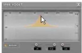
To operate on the parametric equalizer the setup window can also be used (as shown in the image to the side), providing a more detailed setting on the following parameters:
- Operating frequency.
- Parametric pole gain.
- Quality factor Q.

To use this function click on the button to the left of the menu until the orange led lights up. To disable the function click again on the button until the orange led turns off This function can be enabled and disabled also via DRC MP.

8.13 DEVICE INFO

This window shows whether the bit One HD is properly interfaced with the PC and the DRC MP. It also shows the Firmware version for the device and the Serial Number
9. TROUBLESHOOTING
9.1 SYNCHRONIZATION WITH THE PC
1. bit One HD functioning problems
- If, while tuning the system with a laptop PC connected to the bit One HD, should present any functioning problems, try to disconnect the laptop PC power supply cable. In this way, with the laptop PC working on battery power, a possible voltage difference in the USB ground connection between the car (bit One HD) and ground (PC) can be avoided.
2. bit One HD does not connect to PC software
- If, while tuning the system with the PC connected to the bit One HD, the device is switched off and then on again, the connection is lost and the software can not "finalize" the selected setup. If you don't want to lose the modifications and setup previously selected, proceed as follows:
a-save the setup as a file on the PC using the function: FILE / SAVE SETUP;
b- exit the software;
c- turn on the bit One HD;
d-launch the software again;
e- load the setup file again using the function: FILE / LOAD SETUP
3. bit One HD does not respond
- If, while tuning the system with the PC connected to the bit One HD, the device does not respond, proceed as follows
a- turn the bit One HD off:
- by DRC MP, or
- disconnecting the Remote IN, or
- disconnecting the power supply cable for a few seconds;
b- save the setup as a file on the PC using the function: FILE / SAVE SETUP;
c- exit the software;
d- turn on the bit One HD;
e- launch the software again;
f- load the setup file again using the function: FILE / LOAD SETUP.
4. Settings not saved
- In order to successfully complete the bit One HD setup phase and not lose the settings performed, remember to save the selected settings. Select File from the main software menu via the PC and then choose "Finalize to bit One HD".
9.2 BACKGROUND NOISE
Loud whistle /background hiss
In case a loud whistle / background hiss can be heard, it may be necessary to repeat the input sensitivity auto-setup and / or to rectify the output levels adjustment. For more information, see sections 7.2 in this Manual.
9.3 FIRMWARE UPGRADES
If there are product UPGRADES available online, proceed as follows
- Save the previous setup (if you wish to consult it in OFFLINE mode)
- Disconnect the bit One HD "Pre Out".
Start the bit One HD PC software and select TARGET mode.
-
Access the "File" menu in the PC management software and choose "Check for Updates".
-
When you select "Check for Updates", the internet browser in the PC will open up and will automatically search for the URL: www.audisonbitdrive.eu.
Once the related page is open, click on the LINK for the product.
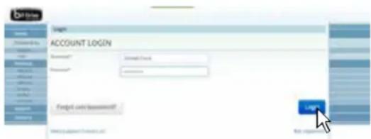
- Identify the newest file whose name includes the word Firmware followed by four numbers and click on the specific symbol to start the download. When requested, save the file to the PC
- Select "Update Firmware". The program will ask you to select the file that was just saved from the Download Area or that was previously saved in the PC.
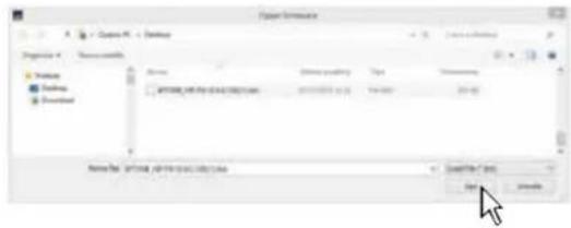

WARNING: the bit One HD Firmware update procedure may be delicate. It is extremely important that it is performed under the best possible conditions.
If the operation is started and prematurely interrupted (e.g.: PC locked up, loss of power to the bit One HD, accidental disconnection of the USB cable during update), our After Sales Service might need to be contacted to reprogram the bit One HD.
-
Before starting the bit One HD update, the program warns you to:
-
not disconnect the bit One HD from the PC;
- not disconnect the bit One HD from power;
- temporarily disable the PC automatic stand-by processes;
- temporarily disable the screen saver on the PC;
- close all running applications;
-
temporarily disable the anti-virus and anti-spyware systems.
-
Once you have clicked on OK, the Firmware update procedure starts. This process will last between 30 seconds and 1 minute; the progress bar and the flashing logo on the bit One HD will show the updating process status.

WARNING: during the update, the progress bar may stop for a few seconds. Do not interrupt the process in any way.
The performed update is displayed on the dialog window. To use the bit One HD again, close the program on the PC and turn off the bit One HD.
- Turn bit One HD back on and restart the PC software. If bit One HD firmware update has been completed correctly, the dialog window will display the following:
- new bit One HD Firmware version.
- Repeat the product calibration operations (see sec. 7.2).


9.4 RESCUE MODE
If there are product UPGRADES available online, proceed as follows:
- save the previous setup (if you wish to consult it in OFFLINE mode);
- disconnect the bit One HD"Pre Out"
- disconnect the bit One HD terminal block.
- place the Upgrade Mode switch to "ON" position.
- connect the bit One HD terminal block. The logo on the product starts flashing.
Start the bit One HD PC software and select "RESCUE MODE".
- Access the "File" menu in the PC management software and choose "Check for Updates".
- When you select "Check for Updates", the internet browser in the PC will open up and will automatically search for the URL: www.audisonbitdrive.eu. Once the related page is open, click on the LINK for the product.
- Identify the newest file whose name includes the word Firmware followed by four numbers and click on the specific symbol to start the download. When requested, save the file to the PC.
- Select "Update Firmware". The program will ask you to select the file that was just saved from the Download Area or that was previously saved in the PC.

WARNING: the bit One HD Firmware update procedure may be delicate. It is extremely important that it is performed under the best possible conditions.
If the operation is started and prematurely interrupted (e.g.: PC locked up, loss of power to the bit One HD, accidental disconnection of the USB cable during update), our After Sales Service might need to be contacted to reprogram the bit One HD.
-
Before starting the bit One HD update, the program warns you to:
-
not disconnect the bit One HD from the PC;
- not disconnect the bit One HD from power;
- temporarily disable the PC automatic stand-by processes;
- temporarily disable the screen saver on the PC;
- close all running applications;
- temporarily disable the anti-virus and anti-spyware systems


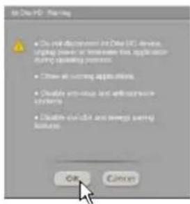
-
Once you have clicked on OK, the Firmware update procedure starts. This process will last between 30 seconds and 1 minute; the progress bar and the flashing logo on the bit One HD will show the updating process status.
-
Place the "UPGRADE" switch to OFF position.
- Disconnect and the connect again the bit One HD terminal block.
- Turn bit One HD back on and restart the PC software. If bit One HD firmware update has been completed correctly, the dialog window will display the following:
- new bit One HD Firmware version.
- Repeat the product calibration operations (see sec. 7.2).


10. TECHNICAL SPECIFICATIONS
POWER SUPPLY
| Voltage 11÷15 VDC | |
| Operating power supply voltage 7.5÷14.4VDC | |
| Idling current 0.75 A | |
| Switched off without DRC MP 2 mA | |
| Switched off with DRC MP 5 mA | |
| Remote IN voltage 6.5÷15 VDC (1mA) | |
| Remote OUT voltage 10÷15 VDC (130 mA) | |
| ART (Automatic Remote Turn ON) 4÷7 VDC | |
| Fuse 2 A | |
| SIGNAL STAGE | |
| Distortion - THD @ 1 kHz, 1 VRMS Output 0.004 % | |
| Bandwidth @ -3 dB 4.5 Hz ÷ 32k Hz | |
| S/N ratio @ A weighted | |
| Master Input | 96 dBA |
| AUX Input | 95 dBA |
| OPTICAL IN1 / IN2 Inputs | 105 dBA |
| Channel Separation @ 1 kHz 77 dBA | |
| Input sensitivity Pre Master 0.7÷6.5 V RMS | |
| Input sensitivity Speaker Master 2÷16 V RMS | |
| Input sensitivity AUX Master | 0.3÷5 V RMS |
| Input impedance Pre In / Speaker In / AUX | 15 kΩ |
| Max Output Level (RMS) @ 0.1% THD | 4 V |
| INPUT STAGE | |
| Low level (Pre) | Ch1÷Ch6, AUX L/R |
| High Level (Speaker In) | Ch1÷Ch12 |
| Digital | 2 x Optical (S/PDIF; Max 192 kHz/24 bit) |
| OUTPUT STAGE | |
| Low level (Pre) | Ch1÷Ch13 |
| Digital AD Link 1 | Ch1÷Ch8 |
| Digital AD Link 2 | Ch9÷Ch13 |
| CONNECTION | |
| From / To Personal Computer 1 x micro USB | |
| To Audison Amplifiers | 2 x (AC Link/AD LINK) control bus |
| To Audison DRC MP | 1 x AC Link |
| CROSSOVER | |
| Filter type | Full / High Pass / Low Pass / Band Pass |
| Filter mode and slope | Linkwitz @ 12 / 24 / 36 / 48 dBButterworth @ 6 / 12 / 18 / 24 / 30 / 36 / 42 / 48 dBBessel @ 6 / 12 / 18 / 24 / 30 / 36 dB |
| Crossover Frequency | 70 steps @ 10÷20k Hz |
| Phase control | 0° / 180° |
| EQUALIZER (20÷20K Hz) | |
| High Level Inputs (Speaker In) | Automatic De-Equalization and Delay compensation |
| AUX Input | Parametric Equalizer: ±12 dB;5 poles |
| OPTICAL IN1/IN 2 Inputs | Parametric Equalizer: ±12 dB;5 poles |
| OUTPUTS | N.13 Parametric Equalizers: ±12 dB;11 poles |
| MAIN EQ | Parametric Equalizer: ±12 dB;5 poles |
| Dynamic Equalization | Self-adjusting System between low and high listening levels |
| Bass Boost | Adjustable parametric pole (±12 dB; 10÷500 Hz) |
| TIME ALIGNMENT | |
| Distance | 1.4÷756 cm / 0.6÷297.7 inches |
| Delay | 0÷22 ms |
| Step | 0.04 ms, 1.4 cm, 0.6 inch |
| GENERAL REQUIREMENTS | |
| PC connections | USB 1.1 / 2.0 / 3.0 Compatible |
| Software/PC requirements | Microsoft Windows (32/64 bit): XP, Vista, Windows 7, Windows 8, Windows 10 |
| Video Resolution with screen resize | min. 800 x 600 |
| Ambient operating temperature range | 0 °C to 55 °C (32°F to 131°F) |
| SIZE | |
| W (Width) x H (Height) x D (Depth) mm/inch | 148 x 43.6 x 233 / 5.82" x 1, 7" x 9.17" |
| Weight kg/lb | 1.775 / 3.9 |
www.audison.eu
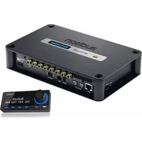
- bit One HD
- USER'S MANUAL
- PRODUCT DESCRIPTION
- PACKAGING CONTENTS
- bit One HD AND DRC MP INSTALLATION
- bit One HD:
- CONNECTION PANELS - DESCRIPTION
- INPUT SIGNALS
- SPEAKERS IN hi-level MASTER input (see section 5.5)
- Ch1 - Ch2 - Ch3 - Ch4 - Ch5 - Ch6 - Ch7 - Ch8 - Ch9 - Ch10 - Ch11 - Ch12
- PRE IN low-level MASTER inputs (see section 5.4.1)
- Ch1 - Ch2 - Ch3 - Ch4 - Ch5 - Ch6
- AUX auxiliary low-level STEREO inputs (see section 5.4.2)
- OPTICAL IN digital inputs (see section 5.6)
- OUTPUT SIGNALS
- POWER SUPPLY / REMOTE IN-OUT (see section 5.1)
- CONNECTIONS
- POWER SUPPLY AND REMOTE TURN ON
- HOW TO TURN THE bit One HD ON/OFF
- PERSONAL COMPUTER and DIGITAL REMOTE CONTROL (DRC MP)
- LOW-LEVEL AND DIGITAL INPUT SIGNALS
- Selection of the MASTER PRE IN input
- AUX - Left/Right - analog STEREO signal
- Selection of the AUX IN input
- "AUTO INPUT SWITCH" AUX SIGNAL
- HIGH-LEVEL INPUT SIGNALS
- SPEAKER IN Hi-level MULTICHANNEL (max 12 CHANNELS)
- MASTER SPEAKER IN input selection
- OPTICAL 1/OPTICAL 2 DIGITAL INPUT SIGNALS
- OPTICAL 1/OPTICAL 2 inputs selection
- "AUTO INPUT SWITCH" OPTICAL 1 / OPTICAL 2 SIGNALS.
- OUTPUT SIGNALS
- AD LINK-OUT / AC LINK
- OUTPUT TO AN AMPLIFIERS SYSTEM PROVIDED WITH AD LINK AND AC LINK CONNECTION (THESIS TH / AV AMPLIFIERS)
- bit One HD SOFTWARE AND DRIVERS - INSTALLATION GUIDE
- SOFTWARE INSTALLATION GUIDE
- DRIVERS INSTALLATION GUIDE FOR WINDOWS XP, VISTA, 7/8/10
- bit One HD SOFTWARE UNINSTALL
- bit One HD SETUP WITH PC
- OFFLINE MODE
- Remark: how to change the size of the PC software window
- TARGET MODE
- Output Analog (Pre Out):
- Guided procedure to set up the desired car audio system.
- Inputs selection
- MASTER LOW-LEVEL INPUTS SELECTION
- How to set up the low-level inputs
- How to calibrate the MASTER inputs levels
- Automatic calibration
- ERROR MESSAGE MAY APPEAR
- "Input Level too low"
- Source de-equalization
- De-equalization procedure
- De-equalization
- Master Input Delay
- Auto Input Switch
- Selection of the speakers available in the system
- Selection of passive crossovers for speaker groups.
- E.g.: the 3-way Front can be managed as:
- Processor outputs (Ch1÷Ch13) allocation.
- Selection of the amplifiers connected through the AD Link / AC Link connection system
- System configuration successfully completed
- MASTER HIGH-LEVEL INPUTS SELECTION
- High-level inputs setup
- MASTER inputs levels calibration
- Selection of passive crossovers for speaker groups
- Processor outputs (Ch1÷Ch13) allocation
- MASTER OPTICAL 1 INPUT SELECTION
- Auto Input Switch
- Selection of the speakers available in the system
- Selection of passive crossovers for speaker groups
- Processor outputs (Ch1÷Ch13) allocation
- Selection of the amplifiers connected through the AD Link / AC Link connection system
- System configuration successfully completed
- bit One HD INSTALLATION GUIDE USING A PC
- Software Start Up
- FEATURES
- MAIN MENU: "FILE" 1
- MAIN MENU: "CONFIG"
- 2
- Functions Description:
- Advanced menu.
- Advanced menu
- MEMORY 3
- SELECT A CHANNEL 4
- LISTENING POSITION VISUAL INDICATOR
- CHANNEL MAP 5
- Output channels multiple selection.
- FILTER SETTINGS 6
- In STANDARD mode:
- In EXPERT mode:
- Cut-off frequencies:
- Filter slope
- - Hi-P Slope
- - Lo-P Slope
- SET DISTANCE AND DELAY 7
- Preliminary remarks
- SET DISTANCE
- DELAY ms/default
- DELAY ms/fine set
- Example of time delay setting (Fig.4):
- EQ SETTINGS
- 8
- OUTPUT LEVEL 9
- SELECT INPUT 10
- SETUP 11
- EASY MODE
- Reset Dynamic EQ
- ADVANCED MODE
- DEVICE INFO
- TROUBLESHOOTING
- SYNCHRONIZATION WITH THE PC
- bit One HD functioning problems
- bit One HD does not connect to PC software
- bit One HD does not respond
- Settings not saved
- BACKGROUND NOISE
- Loud whistle /background hiss
- FIRMWARE UPGRADES
- WARNING: the bit One HD Firmware update procedure may be delicate. It is extremely important that it is performed under the best possible conditions.
- WARNING: during the update, the progress bar may stop for a few seconds. Do not interrupt the process in any way.
- RESCUE MODE
- Start the bit One HD PC software and select "RESCUE MODE".
- TECHNICAL SPECIFICATIONS
Brand : AUDISON
Model : Bit One HD
Category : Audio/video converter