
AMP-220-EUR - Measurement Amprobe - Free user manual and instructions
Find the device manual for free AMP-220-EUR Amprobe in PDF.


| Product Type | Clamp Meter |
| Brand | Amprobe |
| Model | AMP-220-EUR |
| AC Voltage Range | 0-600 V |
| DC Voltage Range | 0-600 V |
| AC Current Range | 0-200 A |
| Resistance Range | 0-40 MΩ |
| Capacitance | 0-100 µF |
| Frequency Measurement | 0-10 kHz |
| Display Count | 4000 counts |
| Clamp Opening | 30 mm |
| Safety Rating | CAT III 600 V |
| Power Supply | 9 V battery |
| Dimensions | 220 x 70 x 40 mm |
| Weight | 300 g |
| Functions | AC/DC voltage, AC current, resistance, continuity, diode, capacitance, frequency, data hold, auto range, backlight |
| Accessories Included | Test leads, battery, user manual |
| Maintenance | Clean with dry cloth; avoid moisture and solvents |
| Repairability | Battery replacement only; no user-serviceable parts inside |
Frequently Asked Questions - AMP-220-EUR Amprobe
User questions about AMP-220-EUR Amprobe
0 question about this device. Answer the ones you know or ask your own.
Ask a new question about this device
Download the instructions for your Measurement in PDF format for free! Find your manual AMP-220-EUR - Amprobe and take your electronic device back in hand. On this page are published all the documents necessary for the use of your device. AMP-220-EUR by Amprobe.
USER MANUAL AMP-220-EUR Amprobe
Limited Warranty and Limitation of Liability
Your Amprobe product will be free from defects in material and workmanship for one year from the date of purchase unless local laws require otherwise. This warranty does not cover fuses, disposable batteries or damage from accident, neglect, misuse, alteration, contamination, or abnormal conditions of operation or handling. Resellers are not authorized to extend any other warranty on the behalf of Amprobe. To obtain service during the warranty period, return the product with proof of purchase to an authorized Amprobe Service Center or to an Amprobe dealer or distributor. See Repair Section for details. THIS WARRANTY IS YOUR ONLY REMEDY. ALL OTHER WARRANTIES - WHETHER EXPRESS, IMPLIED OR STATUTORY - INCLUDING IMPLIED WARRANTIES OF FITNESS FOR A PARTICULAR PURPOSE OR MERCHANTABILITY, ARE HEREBY DISCLAIMED. MANUFACTURER SHALL NOT BE LIABLE FOR ANY SPECIAL, INDIRECT, INCIDENTAL OR CONSEQUENTIAL DAMAGES OR LOSSES, ARISING FROM ANY CAUSE OR THEORY. Since some states or countries do not allow the exclusion or limitation of an implied warranty or of incidental or consequential damages, this limitation of liability may not apply to you.
Repair
All Amprobe returned for warranty or non-warranty repair or for calibration should be accompanied by the following: your name, company's name, address, telephone number, and proof of purchase. Additionally, please include a brief description of the problem or the service requested and include the test leads with the meter. Non-warranty repair or replacement charges should be remitted in the form of a check, a money order, credit card with expiration date, or a purchase order made payable to Amprobe.
In-warranty Repairs and Replacement – All Countries
Please read the warranty statement and check your battery before requesting repair. During the warranty period, any defective test tool can be returned to your Amprobe distributor for an exchange for the same or like product. Please check the "Where to Buy" section on www.Amprobe.com for a list of distributors near you. Additionally, in the United States and Canada, in-warranty repair and replacement units can also be sent to an Amprobe Service Center (see address below).
Non-warranty Repairs and Replacement – United States and Canada
Non-warranty repairs in the United States and Canada should be sent to an Amprobe Service Center. Call Amprobe or inquire at your point of purchase for current repair and replacement rates.
USA: Canada:
Amprobe
Amprobe
Everett, WA 98203 Mississauga, ON L4Z 1X9
Tel: 877-AMPROBE (267-7623) Tel: 905-890-7600
Non-warranty Repairs and Replacement – Europe
European non-warranty units can be replaced by your Amprobe distributor for a nominal charge. Please check the "Where to Buy" section on www.Amprobe.eu for a list of distributors near you.
Amprobe Europe*
Beha-Amprobe
In den Engematten 14
79286 Glottertal, Germany
Tel.: +49 (0) 7684 8009 - 0
www.Amprobe.eu
*(Correspondence only – no repair or replacement available from this address. European customers please contact your distributor.)
CONTENTS
SYMBOL....3
SAFETY INFORMATION .... 4
UNPACKING AND INSPECTION 5
MEASUREMENTS....6
Measuring AC and DC Voltage 7
Voltage detection (NCV) 8
Measuring AC and DC Current 9
Precise Low-Current Measurement 10
Microamps μA Measurement ....11
Measuring Resistance, Continuity and Diode 12
Measuring Capacitance and Temperature 13
Measuring Ⓜ & Ⓡ 3-Phase Rotation ...... 14
Auto Power Off 15
SPECIFICATIONS.... 16
ELECTRICAL SPECIFICATIONS 17
MAINTENANCE AND REPAIR 21
BATTERY REPLACEMENT....21
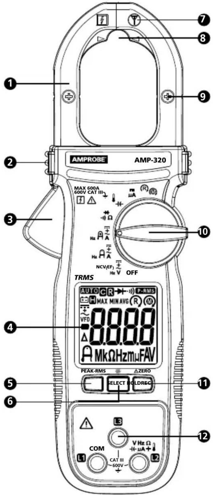
1 Jaw
② Tactile Barrier
3 Jaw Release
4 Display
5 REC/PEAK-RMS Button
6 SELECT/Backlight Button
⑦ Antenna for Non-Contact Voltage Detection
⑧ Precise Low Current Measuring Location
9 Indicator of the Jaw Center for Current Measurement
10 Rotary Switch
11 Data Hold/ZERO button
12 Input Terminals
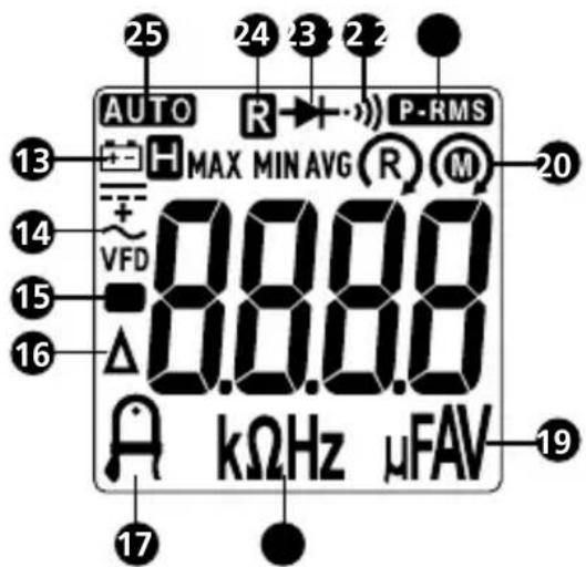
13 Low battery indicator
H Data hold
14 Alternative Current (AC)
--- Direct Current (DC)
AC + DC
VFD Variable Frequency Dive
15 Negative reading
16 △ Relative zero is active
17 Precise low current measurement mode
18 kΩ: KiloOhms
Hz: Hertz
19 μF: Microfarads
μA: Microamps
A: Amps
V: Volts
20 Motor rotation indicator (R) Phase rotation indicator
21 P-FKS RMS mode (in-rush current) is active
22 · continuity buzzer is active
23 → mode test mode is active
24 Recording mode is active
MAX: MAX mode is active
MIN: MIN mode is active
AVG: AVG mode is active
25 AUTO ranging
SYMBOLS
| Application and removal from hazardous live conductors permitted | |
| Caution! Risk of electric shock. | |
| Caution! Refer to the explanation in this manual. | |
| The equipment is protected by double insulation or reinforced insulation. | |
| Earth (Ground). | |
| CAT III | Overvoltage Category III is for equipment intended to form part of a building wiring installation. Such equipment includes socket outlets, fuse panels, and some mains installation control equipment. |
| ~ | Alternating Current (AC). |
| --- | Direct Current (DC). |
| Battery. | |
| Underwriters Laboratories. [Note: Canadian and US.] | |
| CE | Complies with European Directives. |
| Conforms to relevant Australian standards. | |
| Do not dispose this product as unsorted municipal waste.Contact aqualified recycler. |
SAFETY INFORMATION
The Meter complies with:
- UL/IEC/EN 61010-1, CAN/CSA C22.2 No. 61010-1, Pollution Degree 2, Measurement category III 600 V
IEC/EN 61010-2-033
IEC/EN 61010-2-032
• IEC/EN 61010-031 (test leads)
• EMC IEC/EN 61326-1
Measurement Category III (CAT III) is for equipment intended to form part of a building wiring installation. Such equipment includes socket outlets, fuse panels, and some mains installation control equipment.
CENELEC Directives
The instruments conform to CENELEC Low-voltage directive 2006/95/EC and Electromagnetic compatibility directive 2004/108/EC.
⚠️ Warning: Read Before Using
To avoid possible electric shock or personal injury:
- Use the Meter only as specified in this manual or the protection provided by the Meter might be impaired.
- Avoid working alone so assistance can be rendered.
- Never measure AC current while the test leads are inserted into the input jacks.
- Do not use the Meter in wet or dirty environments.
- Do not use the Meter if it appears damaged. Inspect the Meter before use. Look for cracks or missing plastic. Pay particular attention to the insulation around the connectors.
- Inspect the test leads before use. Do not use them if insulation is damaged or metal is exposed.
- Check the test leads for continuity. Replace damaged test leads before using the Meter.
• Have the Meter serviced only by qualified service personnel. - Use extreme caution when working around bare conductors or bus bars. Contact with the conductor could result in electric shock.
- Do not hold the Meter anywhere beyond the tactile barrier.
-
When measuring current, center the conductor in the clamp.
-
Do not apply more than the rated voltage, as marked on the Meter, between the terminals or between any terminal and earth ground.
- Remove test leads from the Meter before opening the Meter case or battery cover.
- Never operate the Meter with the battery cover removed or the case open.
- Never remove the battery cover or open the case of the Meter without first removing the test leads or the jaws from a live conductor.
- Use caution when working with voltages above 30 V ac rms, 42 V ac peak, or 60 V dc. These voltages pose a shock hazard.
- Do not attempt to measure any voltage that might exceed the maximum range of the Meter.
- Use the proper terminals, function, and range for your measurements.
- Do not operate the Meter around explosive gas, vapor, or dust.
- When using probes, keep fingers behind the finger guards.
- When making electrical connections, connect the common test lead before connecting the live test lead; when disconnecting, disconnect the live test lead before disconnecting the common test lead.
- Disconnect circuit power and discharge all high-voltage capacitors before testing resistance, continuity, or diodes.
- Use only 1.5V AAA batteries, properly installed in the Meter case, to power the Meter.
- To avoid false readings that can lead to electrical shock and injury, replace the battery as soon as the low battery indicator ( (-+1) ) appears. Check Meter operation on a known source before and after use.
- When servicing, use only specified replacement parts.
- Adhere to local and national safety codes. Individual protective equipment must be used to prevent shock and arc blast injury where hazardous live conductors are exposed.
- Do not use the Meter if the wear indicator in the jaw opening is not visible.
- Only use the test lead provided with the Meter or UL Listed Probe Assembly rated CAT III 600V or better.
UNPACKING AND INSPECTION
Your shipping carton should include:
1 Clamp meter
1 Test leads
1 Alligator clip set (AMP-310 and AMP-320 only)
1 Banana plug K-type thermocouple (AMP-310 and AMP-320 only)
1 1.5 V AAA batteries (installed)
1 User manual
1 Carrying case
If any of these items are damaged or missing, return the complete package to the place of purchase for an exchange.
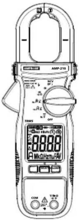
AMP-210 AMP-210-EUR
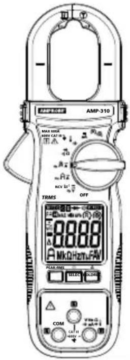
AMP-310 AMP-310-EUR

AMP-220 AMP-220-EUR

AMP-320 AMP-320-EUR
MEASUREMENTS
Warning
To avoid possible electric shock or personal injury:
- When measuring current, center the conductor in the clamp.
- When making current measurements, disconnect the test leads from the Meter.
- Keep fingers behind Tactile Barrier.
• Use the proper function and range for measurements. - Disconnect circuit power and discharge all high-voltage capacitors before testing resistance and diode.
- When using probes, keep fingers behind the finger guards.
- Connecting test leads:
- Connect the common (COM) test lead to the circuit before connecting the live lead;
- After measurement, remove live lead before removing the common (COM) test lead from the circuit.
| Button Description | |
| SELECT / 🌿 | Press SELECT button to select the alternative measurement function on the rotary switch. Press SELECT button > one second to turn ON or to turn OFF LCD backlight. LCD backlight automatically turns off after approximately 32 seconds. |
| HOLD / △ZERO | Press HOLD to freeze the display reading ( H is displayed) and releases the reading when pressed a second time.△ △ WarningTo avoid possible electric shock or personal injury, when Display HOLD is activated, be aware that the display will not change when you apply a different voltage.Press △ ZERO (HOLD) > one second to clear last reading from the display ( △ is displayed) and establish a baseline for applicable selected functions.DC-Zero mode for dc and ac+dc currents. Press △ ZERO (HOLD) > one second to activate DC-Zero (display shows “dc_0” for one second). When nulled value is larger than ± 5 DC A, an acoustic warning (3 short beeps) will occur. |
| REC / PEAK-RMS P | Press REC button to activate maximum, minimum and average reading memory mode ( R MAX MIN AVG is displayed). The meter beeps when MAX and MIN reading is updated during measurement. Press REC button again to read the MAX, MIN and AVG reading in sequence. Press REC button > one second to exit MAX/MIN/AVG reading memory mode.Press REC / PEAK-RMS button > one second to enter PEAK-RMS mode ( P-RMS is displayed) to capture inrush current or voltage RMS values (80 ms). Press a second time > one second to exit.Note: Auto Power Off is automatically disabled under MAX/MIN/AVG and PEAKRMS modes. |
Measuring AC and DC Voltage
To measure ac or dc voltage:
- Turn the rotary function switch to V or
- Press SELECT button to choose measurement function: AC V, DC V, DC+AC V, Hz or EF(Non contact voltage detection). The display reflects the chosen function mode. For Model AMP-210 and AMP-220, NCV(EF) function is designed in an independent rotary switch position. See the Non-Contact Voltage Detection chapter for details.
- Connect the black test lead to the COM terminal and the red test lead to the V terminal. Before connecting the probes to the measurement points, add any clips to the probes that are necessary.
- Measure the voltage by touching the probes to the desired test points of the circuit.
- View the reading on the display.
- When measuring AC voltage, press SELECT button to view the frequency reading on the display.

Note:
- AC V (and hence DC+AC V and Hz) function is equipped with digital low-pass filter, and is capable of dealing with VFD (Variable Frequency Drives) signals. It also improves AC V reading stability in noisy electrical environments.
Voltage Detection (NCV)
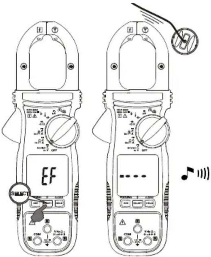
Non-Contact Voltage Detection:
-
For AMP-210 and AMP-220 turn the rotary switch to NCV(EF). "EF" is displayed. For AMP-310 and AMP-320, turn the rotary function switch
to or press SELECT button to toggle to NCV(EF) mode ("EF" is displayed). -
The voltage detection antenna is located along the top-right end of the stationary clamp jaw for detecting electric field surrounds energized conductors
-
Detected electric field signal strength is indicated by a series of bar-graph segments on the display and beeper. The stronger the electric field detected, the more bar-graph segments are displayed and more intense beep sounds.
Measuring AC and DC Current
Warning
To avoid electrical shock and injury:
- Remove Test Leads before making current measurements.
- Do not hold the Meter anywhere beyond the tactile barrier.
- Do not use the Meter to measure currents above the maximum rated frequency (400Hz). Circulating currents may cause the magnetic circuits of the Jaws reach hazardous excessive temperatures.
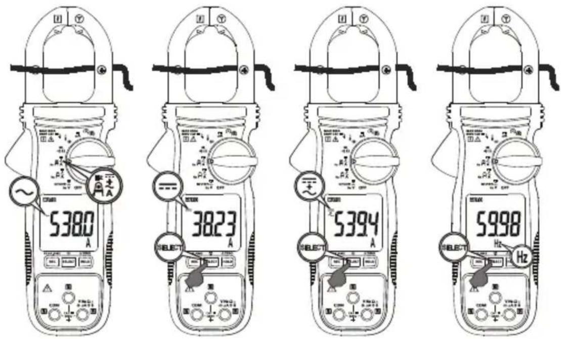
To measure AC or DC current:
- Turn the rotary function switch to
- Press SELECT button to choose measurement function (AC A, DC A, DC+AC A, or Hz). The display reflects the chosen function mode.
- Open the clamp by pressing the jaw release and insert the conductor to be measured into the clamp. Ensure the jaws are firmly closed.
- Close the clamp and center the conductor using the jaw alignment marks.
- View the current reading on the display.
- When measuring AC or AC + DC current, press SELECT button to view the frequency reading on the display.

Caution
During current measurement keep the jaws away from other current-carrying devices such as transformers, motors or energized wires, as they may negatively influence accuracy of the measurement.
Precise Low-Current Measurement
Warning
To avoid electrical shock and injury:
- Remove Test Leads before making current measurements.
- Do not hold the Meter anywhere beyond the tactile barrier.
- Do not use the Meter to measure currents above the maximum rated frequency (400Hz). Circulating currents may cause the magnetic circuits of the Jaws reach hazardous excessive temperatures.
To measure AC or DC low-current for small conductors:
- Turn the rotary function switch to or
- Press SELECT button to choose measurement function (AC A, DC A, DC+AC A, or Hz). The display reflects the chosen function mode.
- Open the clamp by pressing the jaw release and insert the conductor to be measured into the clamp. Ensure the jaws are firmly closed.
- Align the conductor at the specified jaw tip area for low-current measurement
- View the current reading on the display.
- When measuring AC or AC + DC current, press SELECT button to view the frequency reading on the display.

Caution
During current measurement keep the jaws away from other current-carrying devices such as transformers, motors or energized wires, as they may negatively influence accuracy of the measurement.
Microamps μA Measurement
The µ A DC (function on the Meter is primarily for HVAC flame sensor testing. To test a heating system flame sensor:
- Turn the heating unit off and locate the wire between the gas-burner controller and the flame sensor.
- Disconnect one of the flame sensor wires.
- Turn the rotary switch on the Meter to µA .
- Connect the black test lead to the COM terminal and the red test lead to the µ A terminal.
- Using alligator clips, connect a meter in series by attaching one alligator clip to the disconnected flame sensor probe and the second one to the disconnected control-module terminal.
- Turn heating unit on and check the reading on the Meter.
- Refer to the heating unit documentation for what the correct reading should be.

Measuring Resistance, Continuity and Diode
Warning
- To avoid false readings that can lead to electrical shock and injury, de-energize the circuit before taking the measurement.
-
To avoid electrical shock when testing resistance/continuity/diode in a circuit, make sure the power to the circuit is turned off and all capacitors are discharged. Use DC voltage function to check the capacitors are discharged.
-
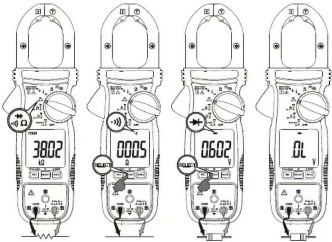
Connect the black test lead to the COM terminal and the red test lead to the Ω terminal.
- Turn the rotary switch to ⋰Ω.
- Press SELECT button for desired measurement function.
- Connect the probes across the circuit or component to be tested.
Resistance measurement: The resistance reading appears on the display. If the circuit is open or resistance exceeds the Meter's range, the display reads "OL".
Continuity measurement: If the circuit is shorted, the Meter beeps and shows a reading ≤ 10 Ω. (Beeper ON ≤ 10 Ω, OFF > 250 Ω) If the circuit is open or resistance exceeds the Meter's range, the display reads OL.
Testing diode: When testing diode, normal forward voltage drop (forward biased) for a good silicon diode is between 0.400V to 0.900V. A reading higher than that indicates a leaky diode (defective). A zero reading indicates a shorted diode (defective). Display reads "OL" indicates an open diode (defective). Reverse the test leads connections (reverse biased) across the diode. The display reads "OL" if the diode is good. Any other readings indicate the diode is resistive or shorted (defective).
Measuring Capacitance and Temperature
Warning
To avoid electrical shock and injury:
- When testing capacitor in a circuit, make sure the power to the circuit is turned off and all capacitors are discharged.
- When measuring temperature, DO NOT apply the temperature probe to any live conductive parts.
Capacitance
- Turn off circuit power, then disconnect and discharge the capacitor before measuring capacitance.
- Connect the black test lead to the COM terminal and the red test lead to the → terminal
- Turn the Meter's rotary switch to capacitance -1€.
- Connect the probes across the capacitor to be tested. When measuring, be sure to note the correct polarity of the capacitor.
Temperature
The Meter measures temperature in either Celsius (°C) or Fahrenheit (°F).
- Connect the banana plug type-K temperature probe to the Meter's input terminal noting correct polarity of the probe.
- Turn the rotary switch to ⚠️.
- Press SELECT button to select °C or °F. The display reflects the chosen temperature mode (°C or °F).
- Position the probe to take the measurement. The reading appears on the display.
Note: Type-K mini plug temperature probes can also be used with a plug adaptor with banana pins to type-K socket.

Measuring ⑬ 3-Phase Rotation
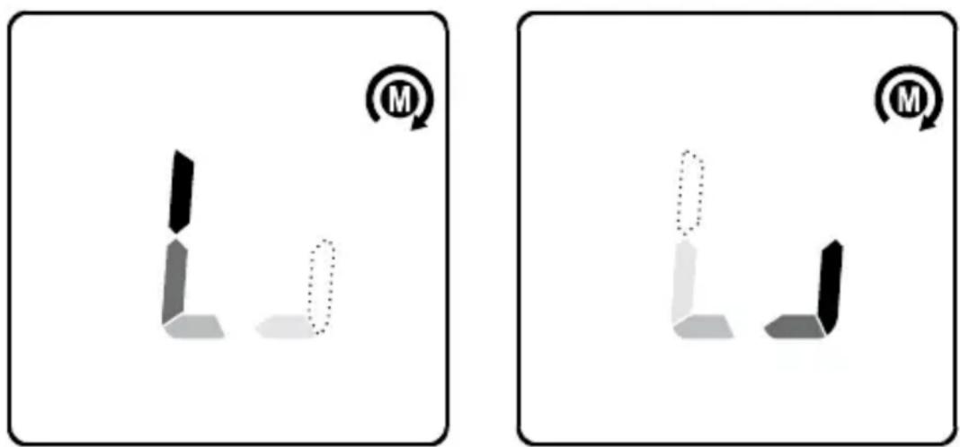
Measurement is made through the Meter's terminals L1/L2/L3. Phase Rotation directions are indicated as symbolic (LCD segments) movements on the display. Default mode at Ⓜ. Press SELECT button to toggle between Ⓜ and ⓜ modes.
(M): Hi-sensitivity mode for checking phase rotation of Motors detects relatively low signal outputs generated spinning a motor shaft,.
(R): Normal-sensitivity mode for identifying phase sequence of 3-phase MAINS supply.
Caution
Correct rotation detection relies on solid signal connection to all three test lead terminals simultaneously. Any loose connection will lead to detection failure and false indication. To verify signal connection and the correct rotation indication, swap any of two signal connections I to check for indication of reverse movement.

Hi-sensitivity mode (for Motors:
Connect the test lead L1/L2/L3 to the motor connections by using probes and/or alligator clips. Be sure the power supply is removed from the motor. From the perspective of looking down the shaft of the motor, speedspin it clockwise to generate sufficient signal strength for rotary detection. If the meter indicates a clockwise movement, the motor leads connected to L1, L2 and L3 of the meter are L1, L2 and L3 (also known as R, S and T), respectively. If the meter indicates a counter-clockwise movement, swap any of two motor connections and retest.
Normal mode (R) for the MAINS circuit:
Connect the test lead L1/L2/L3 to the 3-phase mains circuit by using probes and/or alligator clips. If the meter indicates a clockwise movement, the phases connected to L1, L2 and L3 of the meter are L1, L2 and L3 (also known as R, S and T), respectively. If the meter indicates a counter-clockwise movement, swap any two connects between the meter and phases. Then retest. Connecting the above mentioned L1, L2 and L3 of a motor and that of the MAINS respectively should get a clockwise motor movement.
Using the Beeper feature on Ⓜ & ⓜ mode:
Press and hold the REC button while turning the rotary switch to enable the beeper, the display shows "Enbp". When making rotary measurement, if the rotary indication segments indicate a clockwise movement, the beeper sounds a single long beep per segment cycle. If the rotary indication segments indicate a counter clockwise movement, the beeper sounds 3 short beeps per segment cycle.
natural_image
Two identical 3D geometric shapes with dotted outlines, each marked with a circular icon (no text or symbols)Auto Power Off
The meter turns off if there is no button pushed, rotary function switch operation for 32 minutes and/or no specified activities below, where applicable:
1.) Significant measuring readings of above 8.5% of ranges
2.) Non-OL readings for Resistance, Continuity or Diode function
3.) Non-zero readings for Hz function
4.) Significant movement indication as in Phase Rotation functions
The meter will not enter auto power off mode when under normal measurements. To turn the meter back on, press the SELECT button and release, or turn the rotary switch off and on to restart the meter.
SPECIFICATIONS
| Display | 3-5/6 digits 6000 counts |
| Sensing | True RMS |
| Polarity | Automatic |
| Update rate | 5 per second nominal |
| Operating temperature | 32 °F to 104 °F (0 °C to 40 °C) |
| Relative humidity | Maximum relative humidity 80% for temperature up to 31°C, decreasing linearly to 50% relative humidity at 40 °C |
| Storage temperature | -4 °F to 140 °F (-20 °C to 60 °C), < 80% R.H. (with battery removed) |
| Pollution degree | 2 |
| Operating altitude | ≤ 2000 m |
| Temperature coefficient | nominal 0.15 x (specified accuracy)/°C @(0°C to 18°C or 28°C to 40°C), or otherwise specified |
| Transient Protection | 6.0 kV (1.2/50 μs surge) |
| Overload protections | Current & Hz functions via jaws: 600 A ac/dc rms at < 400HzVoltage & 3-Phase Rotation functions via terminals: 660 V dc / 920 V ac rmsOther functions via terminals: 600 V ac/dc rms |
| E.M.C. | Meets EN61326-1:2006DC A and DC+AC A Functions, in an RF field of 1V/m: Total Accuracy = Specified Accuracy + 20 digits at around 405MHzDC μA and Ohm Functions, in an RF field of 1V/m: Total Accuracy = Specified Accuracy + 25 digitsOther Functions, in an RF field of 3V/m: Total Accuracy = Specified Accuracy + 20 digits |
| Agency approval |   [STTC] [STTC] |
| Power supply | Two 1.5V AAA Size battery |
| Power consumption | Typical 13mA for Current functions; 4.3mA for others |
| Low battery indication | Approx. 2.85 V for Capacitance & Hz; approx. 2.5 V for other functions |
| Auto power off | Idle for 32 minutes |
| Auto power off power consumption | 5μA typical |
| Dimension (L x W x H) | 8.82 x 3.03 x 1.46 in (224 x 77 x 37 mm) for AMP-220 and AMP-3208.62 x 3.03 x 1.46 in (219 x 77 x 37 mm) for AMP-210 and AMP-310 |
| Weight | 254 g (0.56 lb) for AMP-220 and AMP-320 with batteries installed208 g (0.46 lb) for AMP-210 and AMP-310 with batteries installed |
| Jaw opening & conductor diameter | 1.37 in (35 mm) max for AMP-220 and AMP-3201.18 in (30 mm) for AMP-210 and AMP-310 |
ELECTRICAL SPECIFICATIONS
Accuracy is ± (% reading digits + number of digits) or otherwise specified at 23ircC ± 5ircC .
Maximum Crest Factor < 2.5:1 at full scale & < 5:1 at half scale or otherwise specified, and with frequency spectrum not exceeding the specified frequency bandwidth for non-sinusoidal waveforms.
DC Voltage
| Range Accuracy | |
| 600.0V ± (1.0 % + 5 LSD) |
Input Impedance: 10 MΩ, 100 pF nominal
AC Voltage (with Digital Low-Pass Filter)
| Range Accuracy | |
| 600.0V ± (1.0 % + 5 LSD) |
Frequency: 50 Hz to 60 Hz
Input Impedance: 10 MΩ, 100 pF nominal
DC+AC Voltage (with Digital Low-Pass Filter)
(AMP-220 and AMP-320 only)
| Range Accuracy | |
| 600.0V ± (1.2 % + 7 LSD) |
Frequency: DC, 50 Hz to 60 Hz
Input Impedance: 10 MΩ, 100 pF nominal
PEAK-rms (AC V & AC A for AMP-220, AMP-310 and AMP-320 only)
Response: 80 ms to > 90 %
Continuity
Audible Threshold: ON at ≤ 10 Ω ; OFF at > 250 Ω
Response time: 32ms approx.
Resistance
| Range Accuracy | |
| 600.0 Ω, 6.000 kΩ, 60.00 kΩ | ± (1.0 % + 5 LSD) |
Open Circuit Voltage: 1.0VDC typical
Capacitance
| Range Accuracy | 1) |
| 200.0 μF, 2500 μF ± (2.0 % + 4 LSD) | |
1) Accuracy with film capacitor or better
Diode
| Range Accuracy | |
| 2.000 V ± (1.5 % + 5 LSD) |
Test Current: 0.3mA typically
Open Circuit Voltage: < 3.5VDC typically
DC μA (AMP-310 and AMP-320 only)
| Range Accuracy Burden Voltage | ||
| 200.0 μA, 2000 μA ± (1.0 | % + 5 LSD) 3.5 mV/μA | |
Temperature (AMP-310 and AMP-320 only)
| Range Accuracy | |
| -40.0 °C to -10.0 °C ±(1% + 1.5 °C) | |
| >-10 °C to 99.9 °C ±(1% + 0.8 °C) | |
| 100 °C to 400 °C ±(1% + 1 °C) | |
| -40.0 °F to 14.0 °F ±(1% + 3.0 °F) | |
| >14.0 °F to 99.9 °F ±(1% + 1.5 °F) | |
| 100 °F to 752 °F ±(1% + 2 °F) | |
K-type thermocouple accuracy tolerances not included
Precise Low Current AC
| Range Accuracy | 1) 2) 3) 4) |
| 60.00 A | ± (1.5 % + 5 LSD) |
Frequency: 50 Hz to 60 Hz
1) Induced error from adjacent current-carrying conductor: < 0.01 A/A
2) Specified with relative zero Δ mode applied to offset the non-zero residual readings, if any.
3) Add 10 LSD to the specified accuracy @ < 4 A
4) AMP-210 and AMP-310, not specified @ < 0.2 A
Precise Low Current DC (AMP-220 and AMP-320 only)
| Range Accuracy | 1) 2) 3) |
| 60.00 A ± (2.0 % + 5 LSD) |
1) Induced error from adjacent current-carrying conductor: < 0.01 A/A
2) Specified with DC-zero mode applied to offset the non-zero residual readings, if any
3) Add 10 LSD to the specified accuracy @ < 4 A
Precise Low Current DC+AC (AMP-220 and AMP-320 only)
| Range Accuracy | 1) 2) 3) |
| 60.00 A ± (2.0 % + 5 LSD) |
Frequency: DC, 50 Hz to 60 Hz
1) Induced error from adjacent current-carrying conductor: < 0.01 A/A
2) Specified with DC-zero mode applied to offset the non-zero residual readings, if any
3) Add 10 LSD to the specified accuracy @ < 4 A
AC Current
| Range Accuracy | 1) 2) 3) |
| 60.00 A 4) 5), 600.0 A ± (1.8 % | + 5 LSD) @ 50 Hz to 100 Hz |
| 60.00 A 4) 5), 600.0 A ± (2.0 % | + 5 LSD) @ 100 Hz to 400 Hz |
1) Induced error from adjacent current-carrying conductor: < 0.01 A/A
2) AMP-220 and AMP-320: maximum crest factor < 2:1 at full scale & < 4:1 at half scale
3) AMP-210 and AMP-310: specified accuracy is for measurements made at the jaw center. When the conductor is not positioned at the jaw center, add 2% to specified accuracy for position errors
4) AMP-220 and AMP-320: add 10 LSD to the specified accuracy @ < 9 A
5) AMP-210 and AMP-310: add 10 LSD to specified accuracy @ < 6 A, and not specified @ < 0.2 A
DC Current (AMP-220 and AMP-320 only)
| Range Accuracy | 1) 2) 3) |
| 60.00 A 3) , 600.0 A ± (2.0 % + | 5 LSD) |
1) Induced error from adjacent current-carrying conductor: < 0.01 A/A
2) Specified with DC-zero mode applied to offset the non-zero residual readings, if any
3) Add 10 LSD to the specified accuracy @ < 9 A
DC+AC Current (AMP-220 and AMP-320 only)
| Range Accuracy | 1) 2) |
| 60.00 A3), 600.0 A ± (2.2 % + | 7 LSD) @ DC, 50 Hz to 100 Hz |
| 60.00 A3), 600.0 A ± (2.7 % + | 7 LSD) @ 100 Hz to 400 Hz |
1) Induced error from adjacent current-carrying conductor: < 0.01 A/A
2) Specified with DC-zero mode applied to offset the non-zero residual readings, if any
3) Add 10 LSD to the specified accuracy @ < 9 A
Frequency Hz
| Function Sensitivity | 1) (Sine rms) Range |
| 600 V 50 V 5.00 Hz to 999.9 Hz | |
| 60 A (Precise low current) 40 A 50.00 Hz to 400.0 Hz | |
| 60 A, 600 A 40 A 50.00 Hz to 400.0 Hz |
Accuracy: ± (1.0 % + 5 LSD)
1) DC-bias, if any, not more than 50% of Sine rms
⑧ & ⑨ Phase Rotation
measurement:
Voltage Range: 65 V to 600 V (sine wave only)
Frequency Range: 35 Hz to 400 Hz
® measurement:
Voltage Range: 0.4 V to 600 V (sine wave only)
Frequency Range: 3 Hz to 400 Hz
Voltage Detection (NCV)
| Typical Voltage Bar-graph Indication | |
| 20 V (tolerance: 10 V to 36 V) - | |
| 55 V (tolerance: 23 V to 83 V) - - | |
| 110 V (tolerance: 59 V to 165 V) - - - | |
| 220 V (tolerance: 124 V to 330 V) - - - - | |
| 440 V (tolerance: 250 V to 600 V) - - - - - |
Indication: bar-graph segments and audible beep tones proportional to the field strength
Detection frequency: 50/60 Hz
Detection antenna: inside the top side of the stationary jaw
MAINTENANCE AND REPAIR
If the Meter fails to operate, check battery, test leads, etc., and replace as necessary.
Double check the following:
- Replace the fuse or battery if the meter does not work.
- Review the operating instructions for possible mistakes in operating procedure.
Except for the replacement of the battery, repair of the meter should be performed only by a Factory Authorized Service Center or by other qualified instrument service personnel.
The front panel and case can be cleaned with a mild solution of detergent and water. Apply sparingly with a soft cloth and allow to dry completely before using. Do not use aromatic hydrocarbons, gasoline or chlorinated solvents for cleaning.
BATTERY REPLACEMENT
When battery voltage drops below the value required for proper operation, the battery symbol (☐) appears.
Warning
To avoid shock, injury, or damage to the Meter, disconnect test leads before opening case.
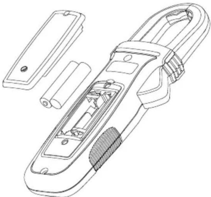
Replacing BATTERY follow below steps:
- Disconnect the test lead probe from measuring circuit.
- Turn the Meter to OFF position.
- Remove the screws from the battery cover and open the battery cover
- Remove the batteries and replace with 1.5V AAA Size (IEC R03). Observe correct polarity when installing the batteries.
- Put the battery cover back and re-fasten the screw. Battery: 2 x 1.5 V AAA (IEC R03)
natural_image
Technical line drawing of a handheld device with internal components and housing (no text or symbols)Visit www.Amprobe.com for
- Catalog
• Application notes
• Product specifications - User manuals
Amprobe®
www.Amprobe.com
info@amprobe.com
Everett, WA 98203
Tel: 877-AMPROBE (267-7623)
Amprobe® Europe
Beha-Amprobe
In den Engematten 14
79286 Glottertal, Germany
Tel.: +49 (0) 7684 8009 - 0

Please
Recycle
- Limited Warranty and Limitation of Liability
- Repair
- In-warranty Repairs and Replacement – All Countries
- Non-warranty Repairs and Replacement – United States and Canada
- Non-warranty Repairs and Replacement – Europe
- CONTENTS
- SAFETY INFORMATION
- CENELEC Directives
- ⚠️ Warning: Read Before Using
- UNPACKING AND INSPECTION
- MEASUREMENTS
- Warning
- Measuring AC and DC Voltage
- Note:
- Voltage Detection (NCV)
- Non-Contact Voltage Detection:
- Measuring AC and DC Current
- To avoid electrical shock and injury:
- To measure AC or DC current:
- Caution
- Precise Low-Current Measurement
- To measure AC or DC low-current for small conductors:
- Microamps μA Measurement
- Measuring Resistance, Continuity and Diode
- Measuring Capacitance and Temperature
- Capacitance
- Temperature
- Measuring ⑬ 3-Phase Rotation
- Hi-sensitivity mode (for Motors:
- Normal mode (R) for the MAINS circuit:
- Using the Beeper feature on Ⓜ & ⓜ mode:
- Auto Power Off
- ELECTRICAL SPECIFICATIONS
- DC+AC Voltage (with Digital Low-Pass Filter)
- Continuity
- Resistance
- Diode
- DC μA (AMP-310 and AMP-320 only)
- Temperature (AMP-310 and AMP-320 only)
- Precise Low Current AC
- ⑧ & ⑨ Phase Rotation
- measurement:
- ® measurement:
- MAINTENANCE AND REPAIR
- BATTERY REPLACEMENT
- Replacing BATTERY follow below steps:
- Visit www.Amprobe.com for
- Amprobe®
- Amprobe® Europe
Brand : Amprobe
Model : AMP-220-EUR
Category : Measurement