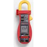
ACD-45PQ - Measurement Amprobe - Free user manual and instructions
Find the device manual for free ACD-45PQ Amprobe in PDF.


| Product Type | Digital Clamp Meter |
| Brand | Amprobe |
| Model | ACD-45PQ |
| Measurement Functions | AC/DC Voltage, AC Current, Resistance, Capacitance, Frequency, Temperature, Diode Test, Continuity |
| AC Voltage Range | 0 to 750V |
| DC Voltage Range | 0 to 1000V |
| AC Current Range | 0 to 1000A |
| Resistance Range | 0 to 40 MΩ |
| Capacitance Range | 0 to 4000 μF |
| Frequency Range | 0 to 10 kHz |
| Temperature Measurement | -20°C to 1000°C (with thermocouple) |
| Jaw Opening | 30 mm (approx. 1.2 in) |
| Display | LCD, 4000 counts, with backlight |
| Safety Rating | CAT III 600V, CAT II 1000V |
| Power Supply | 9V battery (NEDA 1604, 6LF22) |
| Dimensions | 250 x 70 x 40 mm (9.8 x 2.8 x 1.6 in) |
| Weight | Approx. 300 g (10.6 oz) |
| Maintenance and Cleaning | Wipe with a damp cloth; do not use abrasives or solvents. Calibrate annually. |
| Safety Precautions | Do not exceed rated voltage/current. Use proper PPE. Disconnect test leads before changing battery. |
| Spare Parts and Repairability | Replaceable test leads, battery, and fuse. Contact Amprobe service for repairs. |
Frequently Asked Questions - ACD-45PQ Amprobe
User questions about ACD-45PQ Amprobe
0 question about this device. Answer the ones you know or ask your own.
Ask a new question about this device
Download the instructions for your Measurement in PDF format for free! Find your manual ACD-45PQ - Amprobe and take your electronic device back in hand. On this page are published all the documents necessary for the use of your device. ACD-45PQ by Amprobe.
USER MANUAL ACD-45PQ Amprobe
natural_image
Abstract geometric logo composed of white triangles on black background (no text or symbols)AMPROBE®
ACD-45PQ
600A Power Quality Clamp
Users Manual
- Mode d'emploi
• Bedienungshandbuch - Manual d'Uso
- Manual de uso
ACD-45PQ
600A Power Quality Clamp
Users Manual
Limited Warranty and Limitation of Liability
Your Amprobe product will be free from defects in material and workmanship for 1 year from the date of purchase. This warranty does not cover fuses, disposable batteries or damage from accident, neglect, misuse, alteration, contamination, or abnormal conditions of operation or handling. Resellers are not authorized to extend any other warranty on Amprobe's behalf. To obtain service during the warranty period, return the product with proof of purchase to an authorized Amprobe Test Tools Service Center or to an Amprobe dealer or distributor. See Repair Section for details. THIS WARRANTY IS YOUR ONLY REMEDY. ALL OTHER WARRANTIES - WHETHER EXPRESS, IMPLIED OR STAUTORY - INCLUDING IMPLIED WARRANTIES OF FITNESS FOR A PARTICULAR PURPOSE OR MERCHANTABILITY, ARE HEREBY DISCLAIMED. MANUFACTURER SHALL NOT BE LIABLE FOR ANY SPECIAL, INDIRECT, INCIDENTAL OR CONSEQUENTIAL DAMAGES OR LOSSES, ARISING FROM ANY CAUSE OR THEORY. Since some states or countries do not allow the exclusion or limitation of an implied warranty or of incidental or consequential damages, this limitation of liability may not apply to you.
Repair
All test tools returned for warranty or non-warranty repair or for calibration should be accompanied by the following: your name, company's name, address, telephone number, and proof of purchase. Additionally, please include a brief description of the problem or the service requested and include the test leads with the meter. Non-warranty repair or replacement charges should be remitted in the form of a check, a money order, credit card with expiration date, or a purchase order made payable to Amprobe® Test Tools.
In-Warranty Repairs and Replacement – All Countries
Please read the warranty statement and check your battery before requesting repair. During the warranty period any defective test tool can be returned to your Amprobe® Test Tools distributor for an exchange for the same or like product. Please check the "Where to Buy" section on www.amprobe.com for a list of distributors near you. Additionally, in the United States and Canada In-Warranty repair and replacement units can also be sent to a Amprobe® Test Tools Service Center (see next page for address).
Non-Warranty Repairs and Replacement – US and Canada
Non-warranty repairs in the United States and Canada should be sent to a Amprobe® Test Tools Service Center. Call Amprobe® Test Tools or inquire at your point of purchase for current repair and replacement rates.
In USA In Canada
Amprobe Test Tools Amprobe Test Tools
Everett, WA 98203 Mississauga, ON L4Z 1X9
Tel: 888-993-5853 Tel: 905-890-7600
Fax: 425-446-6390 Fax: 905-890-6866
Non-Warranty Repairs and Replacement – Europe
European non-warranty units can be replaced by your Amprobe® Test Tools distributor for a nominal charge. Please check the "Where to Buy" section on www.amprobe.com for a list of distributors near you.
Amprobe® Test Tools Europe
In den Engematten 14
79286 Glottertal, Germany
tel: +49 (0) 7684 8009 - 0
*(Correspondence only – no repair or replacement available from this address. European customers please contact your distributor.) customers please contact your distributor.)
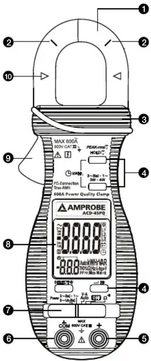
1 Transformer Clamp Jaws for AC current magnetic field pick up
② Jaw marking lines for ACA (& thus Power) position error indication
3 Hand/Finger Barrier to indicate the limits of safe access to the jaws during current measurements
4 Push-buttons for special functions & features
⑤ Input Jack for all functions EXCEPT non-invasive ACA current (& thus Power) function
6 Common (Ground reference) Input Jack for all functions EXCEPT non-invasive ACA current (& thus Power) function
7 Slide-switch Selector to turn the power ON/OFF and Select a function
8 LCD display
9 Jaw trigger for opening the transformer clamp jaws
10 Jaw center Indicators, at where best ACA (& thus Power) accuracy is specified
CONTENTS
SYMBOLS....1
UNPACKING AND INSPECTION ....3
OPERATION....3
AutoVA ^TM Function 4
Peak-rms Mode 5
Line-level Frequency (Hz) Function ....5
HOLD Mode....6
Single-Phase Power & 3-Phase Balanced-Load Power Functions ....8
kWHr (kilo-Watt-Hour) Recording Function 9
3-Phase 3-Wire (3\~3W) Unbalanced-Load Power Function .....11
3-Phase 4-Wire (3\~4W) Unbalanced-Load Power Function .....12
Ω/•)) Functions ....14
Backlighted Display 14
Auto Power Off (APO) 14
Auto Power Off Quick Test 15
Disabling Auto-Power-Off (APO) 15
Line Frequency Setup ....15
PC Computer Interface Capabilities) 15
SPECIFICATIONS....16
MAINTENACE AND REPAIR....22
Trouble Shooting....22
Cleaning and Storage 22
Battery Replacement 23
SYMBOLS
| Caution! Risk of electric shock | |
| Caution! Refer to the explanation in this Manual | |
| Double Insulation or Reinforced insulation | |
| Alternating Current (AC). | |
| Direct Current (DC). | |
| Fuse | |
| Earth (Ground) | |
| Please remove all the test leads before preforming maintenance, cleaning, battery replacement, fuse replacement, etc | |
| CE | Complies with European Directives |
| Conforms to relevant Australian standards | |
| Do not dispose of this product as unsorted municipal waste. Contact a qualified recycler for disposal |
Safety Information
This manual contains information and warnings that must be followed for operating the instrument safely and maintaining the instrument in a safe operating condition. If the instrument is used in a manner not specified by the manufacturer, the protection provided by the instrument may be impaired. The meter is intended only for indoor use.
The meter protection rating, against the users, is double insulation per IEC61010-1 2nd Ed., EN61010-1 2nd Ed., UL61010-1 2nd Ed. and CAN/CSA C22.2 No. 61010.1-0.92 to Category III 1000 Volts AC & DC and Category IV 600 Volts AC & DC.
Per IEC61010-1 2nd Ed. (2001) Measurement Category
Measurement Category IV (CAT IV) is for measurements performed at the source of the low-voltage installation. Examples are electricity meters and measurements on primary overcurrent protection devices and ripple control units.
Measurement Category III (CAT III) is for measurements performed in the building installation. Examples are measurements on distribution boards, circuit-breakers, wiring, including cables, bus-bars, junction boxes, switches, socket-outlets in the fixed installation, and equipment for industrial use and some other equipment, for example, stationary motors with permanent connection to the fixed installation.
Measurement Category II (CAT II) is for measurements performed on circuits directly connected to the low voltage installation. Examples are measurements on household appliances, portable tools and similar equipment.
Terms In This Manual
⚠ WARNING - identifies conditions and actions that could result in serious injury or even death to the user.
⚠️ CAUTION - identifies conditions and actions that could cause damage or malfunction in the instrument.
⚠ WARNING - To reduce the risk of fire or electric shock, do not expose this product to rain or moisture.
To avoid electrical shock hazard, observe the proper safety precautions when working with voltages above 60 VDC or 30 VAC rms. These voltage levels pose a potential shock hazard to the user.
Keep your fingers behind the finger guards of the test leads during measurement. Inspect test leads, connectors, and probes for damaged insulation or exposed metal before using the instrument. If any defects are found, replace them immediately.
This Clamp-on meter is designed to apply around or remove from uninsulated hazardous live conductors. But still, individual protective equipment must be used if hazardous live parts in the installation where measurement is to be carried out could be accessible.
⚠️ CAUTION - Disconnect the test leads from the test points before changing meter functions. Only use the accompanied test leads, or replace with the same rating or better.
CENELEC Directives
The instruments conform to CENELEC Low-voltage directive 2006/95/EC and Electromagnetic compatibility directive 2004/108/EC
Your shipping carton should include:
1 ACD-45PQ 600A Power Quality Clamp
1 Test Leads (Black x 1; Red x 1)
1 Bag
1 Users Manual
2 1.5V AAA LR03/NEDA 24A Batteries (Installed)
If any of the items are damaged or missing, return the complete package to the place of purchase for an exchange.
OPERATION
⚠️ CAUTION
Before and after hazardous voltage measurements, test the voltage function on a known source such as line voltage to determine proper meter functioning.
AutoVA™ Function
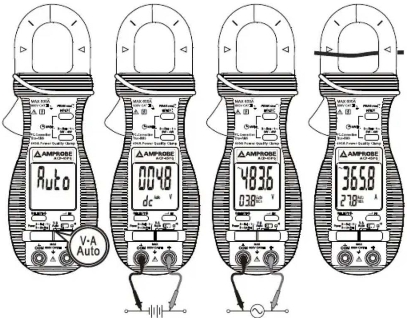
Set the slide-switch function-selector to the V-A Auto position.
- With no input, the meter displays "Auto when it is ready.
- With no ACA current input via the jaws but a voltage signal above the nominal threshold of DC 2.4V or AC 30V (40Hz \~ 500Hz) up to the rated 600V is present on V-COM terminals, the meter displays the voltage value in appropriate DC or AC, whichever larger in peak magnitude. Annunciators "Auto" "dc" and "Auto" "\~" turn on respectively.
- On the contrary, with no voltage signal present on V-COM terminals but a ACA current signal above the nominal threshold of AC 1A (40Hz \~ 500Hz) up to the rated 600A is input via the jaws, the meter displays the ACA current value. Annunciators “\~” and “Auto” turn on accordingly.
- The Auto-VA feature stays at the auto-selected function as long as its signal remains above the specified threshold. Press SELECT button momentarily to manually select and lock (annunciator "Auto" turns off) thru the functions ACA, ACV, DCV and then goes back to Auto-VA.
⚠️ CAUTION
- For non-invasive ACA current measurements, press the jaw trigger and clamp the jaws around only one single conductor of a circuit for load current measurement. Make sure the jaws are completely closed, or else it will introduce measurement errors. Enclosing more than one conductor of a circuit will result in differential current (like identifying leakage current) measurement. Locate the conductor(s) at the Jaws center as much as possible to get the best measuring accuracy. For removal, press the jaw trigger and remove the jaws from the conductor(s).
- Adjacent current-carrying devices such as transformers, motors and conductor wires will affect measurement accuracy. Keep the jaws away from them as much as possible to minimize influence.

Peak-rms Mode
Peak-rms Hompares and displays the maximum RMS value of surge voltage or current with durations as short as 65ms. When ACV or ACA function is auto-selected or manual-selected, press and hold Peak-rms H button for one second or more toggles to this mode. The annunciators "P-" "Max" turn on. APO (Auto Power Off) feature is disabled automatically accordingly.
In ACA function, the Peak-rms mode starts at the highest 600A range to maximize measuring dynamic range. Before making measurement, press the Peak-rms 📄 button momentarily again can manually select thru lower measuring dynamic range 400.0A or 40.00A for higher measuring resolutions.
Line-level Frequency (Hz) Function
When ACV or ACA function is auto-selected or manual-selected, press Hz button momentarily toggles to Line-level Frequency (Hz) function. The Hz trigger level is determined by the selected function-range from where the Hz function is activated.
In ACA function, activating the Hz function during significant measurements can get the most appropriate trigger level to avoid electrical noises in most cases. Activating the Hz function at AC 40.00A range (before making significant measurements) can get the lowest trigger level (highest sensitivity).
HOLD Mode
When any function is auto-selected or manual-selected, press HOLD Button momentarily toggles to Hold mode. The annunciator "H" turns on. Hold mode freezes the display for later viewing.
Notes on Displacement Power Factor & Total Power Factor
- Introduction: Power is the rate of change of energy with respect to time (in terms of voltage V and current A). Instantaneous (real) power w = vi where v is the instantaneous voltage and i the instantaneous current. The average (real) power is the mean of vi and is given by:
W = / 2 fvi dt , over the interval from 0 to 2/
- Displacement Power Factor (more traditional): Assuming V and A are pure sinusoidal waveforms without harmonics (as in most traditional cases), that is, v = V t and i = I ( t - ) , the expression can be simplified to:
W = 1/2 × V × I × where V and I are the peak values, is the displacement power factor angle, and is the displacement power factor. Using RMS values, it is written as:
W = Vrms x Arms x Cosθ
Practically, in such cases without harmonics, is also called the phase-shift angle of the current A to the voltage V. An inductive circuit is said to have a lagging power factor since current A lags voltage V (phase-shift angle and thus are both “+”), and a capacitive circuit is said to have a leading power factor since current A leads voltage V (phase-shift angle and thus are both “-”).
- Total Power Factor (encountering harmonics): When encountering distorted waveforms with the presence of harmonics, however, the simplified power expression should not be used since substituting the above mentioned pure sinusoidal V and A functions cannot fulfill the actual conditions. Cosine of phase-shift angle (Cosθ), or the displacement
power factor, is no longer the only component constituting the overall power factor. Harmonics do increase apparent power and thus decrease the overall power factor.
That is the Total Power Factor is actually affected by both phase-shift angle and harmonics, and is given by the expression:
Total Power Factor (PF) = Real Power (W) / Apparent Power (VA)
In order to improve overall system power factor, nowadays power-system engineer needs to address both phase-shift and harmonics problems. Practically, harmonics should be dealt with (e.g. filtering out) before phase-shift to be corrected (e.g. installing capacitors in parallel with inductive loads).

Single-Phase Power & 3-Phase Balanced-Load Power Functions
Set the slide-switch function-selector to the "3\~Bal • 1\~" Power position.
- Default at last selected function.
- Press "3\~Bal • 1\~" button momentarily to toggle between "Single-Phase" and "3-Phase Balanced Load" Power functions. Annunciators "\~" and "3\~" turn on respectively.
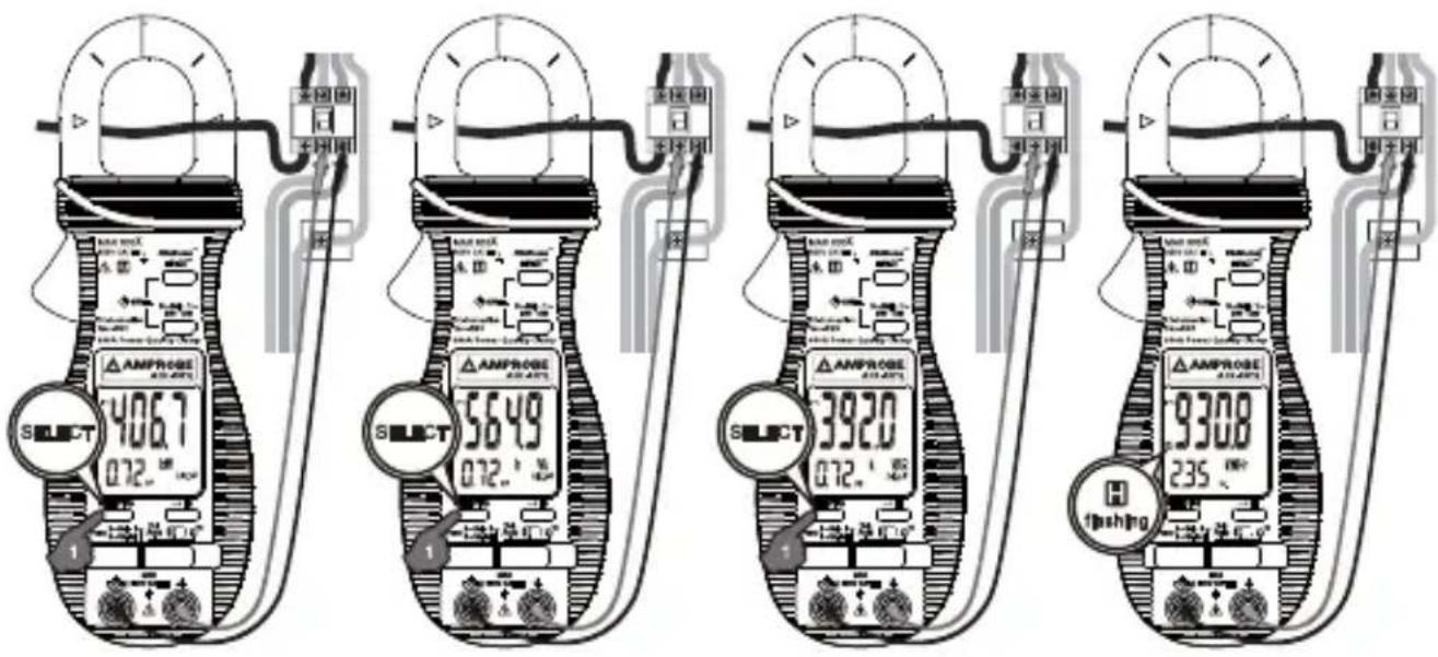
- Press SELECT button momentarily selects between W (real power), VAR (reactive power), VA (apparent power) & kWhr (real-time readings or stored result) functions. In W (real power), VAR (reactive power), or VA (apparent power) function:
- PF (Total Power Factor) is displayed automatically in the secondary mini display.
- Annunciator "A-lags-V" turns on to indicate an inductive circuit is being measured. That is, the Current waveform is lagging the Voltage waveform, and the phase-shift angle is "+".
- On the contrary, together with significant PF values, WITHOUT "A-lags-V" being turned on indicates that a capacitive circuit is being measured. That is, the Current waveform is leading the Voltage waveform, and the phase-shift angle is "-".
Note:
-
Under proper measurement setups for load circuits, the W (real power) readings are always positive. Negative W readings indicate reversed clamp-on jaws direction or test leads polarities, or even incorrect voltage lines are being measured as in 3-phase measurement setups. Correct them for proper "A-lags-V" indications.
-
When encountering largely distorted waveforms, "A-lags-V" detection might be affected due to the influence of harmonics. It is recommended to manage (e.g. filter out) harmonics problems before measuring/ dealing with phase-shift problems.
kWHr (kilo-Watt-Hour) Recording function

Set the slide-switch function-selector to the "3\~Bal • 1\~" Power position. Setup power measurements as mentioned in the previous "Single-Phase Power & 3-Phase Balanced-Load Power functions" section
- To start ("Strt") kWhr Recording, press "3\~Bal • 1\~" and "HOLD" buttons at the same time. Annunciator "💡" turns on & flashes. kWhr accumulated time (in Hour) is displayed automatically in the secondary mini display.
- To pause ("PRUS"), press "HOLD" button momentarily. Annunciator " stops flashing and is always on.
- To continue ("font"), press the "HOLD" button momentarily again. Annunciator "💡" resumes flashing.
- To stop ("Stop"), press the "3\~Bal • 1\~" and "HOLD" buttons at the same time again. Annunciator "💡" turns off. The kWhr Recording result is then displayed on the LCD for immediate viewing. Annunciator "H" turns on & flashes.
- When the low battery annunciator “+−” turns on, the meter will stop (“Stop”) kWhr recording session automatically and display kWhr Recording result as in above.
Note:
- During kWhr Recording session, real-time W, VAR, VA as well as kWhr accumulated readings can be selected by pressing the SELECT button momentarily. A flashing “💡” denotes that kWhr Recording is still undergoing. An always on “💡” denotes that kWhr Recording is being paused.
- When kWhr Recording is not activated, kWhr stored result instead of accumulated readings is displayed when selected as in above. Annunciator "H" turns on & flashes.
- The meter separately stores one Single-Phase and one 3-Phase-Balanced-Load kWhr result for later viewing. When they are being viewed, press "3\~Bal • 1\~" button momentarily to toggle between them.
- When the display readings exceed 9999kWHr/999hours, exponential readings are displayed. "2.3E4" kWhr represents 2.3 x 10⁴ kWhr, or 23000 kWhr for example,.
- After the kWhr Recording session is stopped ("So") properly, the new result will supersede the previous one stored in the non-volatile memory. You can then switch off the meter for transportation, storage, or even battery changing with memory remained.
- To avoid mis-storage to memory, it is important to properly stop ("Stop") kWhr Recording session before sliding the slide-switch function-selector to any other function positions.
3-Phase 3-Wire (3\~3W) Unbalanced-Load Power Function
- Set the slide-switch function-selector to the "3\~Un-Bal" Power position. Press "3W•4W" button momentarily to select 3-Wire measurements. Annunciator "3W" turns on.
- Clamp the jaws around "Line 1" as reminded by annunciators "A L1", and connect Black test probe (COM terminal) to "Line 3" and Red test probe (+ terminal) to "Line 1" as reminded by annunciators "V 3"-on mini-display.
- When the reading is stable, press “←” button momentarily to enter the first measuring value.
- Then clamp the jaws around "Line 2" as reminded by annunciators "A L2", and connect Black test probe (COM terminal) to "Line 3" and Red test probe (+ terminal) to "Line 2" as reminded by annunciators "V 3-2" on mini-display.
- When the reading is stable, press "←" button momentarily to enter the second measuring value. The meter will then calculate, store and display the total 3-Phase Power result automatically. Annunciators "A L1 L2 L3" turn on.
- Press “←” button momentarily again for new measurements.
- Press "SELECT" button momentarily to view ("") the last stored result. Annunciator "H" turns on & flashes. Press "SELECT" button momentarily again to continue ("cont").

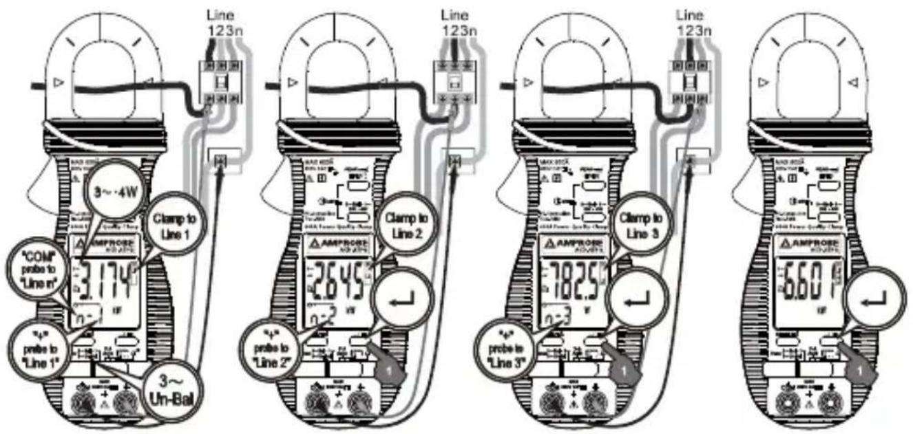
3-Phase 4-Wire (3 4W) Unbalanced-Load Power Function
- Set the slide-switch function-selector to the "3\~Un-Bal" Power position. Press "3W•4W" button momentarily to select 4-Wire measurements. Annunciator "4W" turns on.
- Clamp the jaws around "Line 1" as reminded by annunciators "A L1", and connect Black test probe (COM terminal) to "Line n (neutral)" and Red test probe (+ terminal) to "Line 1" as reminded by annunciators "V n - 1" on mini-display.
- When the reading is stable, press "←" button momentarily to enter the first measuring value.
- Then clamp the jaws around "Line 2" as reminded by annunciators "L2", and connect Black test probe (COM terminal) to "Line n (neutral)" and Red test probe (+ terminal) to "Line 2" as reminded by annunciators "Vn" on mini-display.
- When the reading is stable, press “←” button momentarily to enter the second measuring value.
- Then clamp the jaws around "Line 3" as reminded by annunciators "L3", and connect Black test probe (COM terminal) to "Line n (neutral)" and Red test probe (+ terminal) to "Line 3" as reminded by annunciators "Vn" on mini-display.
- When the reading is stable, press “ ” button momentarily to enter the third measuring value. The meter will then calculate, store and display the total 3-Phase Power result automatically. Annunciators “A L1 L2 L3” turn on.
- Press "←" button momentarily again for new measurements.
- Press "SELECT" button momentarily to view ("[RE]) the last stored result. Annunciator "H" turns on & flashes. Press "SELECT" button momentarily again to continue ("[ont]).
Ω/Functions
Set the slide-switch function-selector to the / function position. Default at last selected function. Press SELECT button to toggle between and measurement functions.

Backlighted Display
Press the SELECT button for 1 second or more to toggle the display backlight on or off.
Auto Power Off (APO)
The meter turns off after approximately 30 minutes of neither switch nor button activity. To wake up the meter from APO, press SELECT button or slide the function-selector to OFF position and back on again. Always turn the function-selector to OFF when the meter is not in use.
Auto Power Off Quick Test
Press-and-hold the 3W.4W button while powering the meter on. The LCD displays "SLP." & "F" to confirm activation right after the 3W.4W button is released. Quick test APO timing is 10 seconds after such activation.
Disabling Auto-Power-Off (APO)
Press-and-hold the HOLD button while powering the meter on. The LCD displays "SLP-" & "OFS" to confirm activation right after the HOLD button is released.
Line Frequency Setup
Press-and-hold the Hz button while powering the meter on. LCD displays the last 50Hz or 60 Hz setup. Press SELECT button momentarily to select 50Hz or 60Hz to cope with your local line frequency. Press Hz button for one second to store your selection and resume measurements.
PC Computer Interface Capabilities
The instrument equips with an optical isolated data output port at the bottom case near the battery compartment. Optional purchase PC interface kit USB-KIT2 is required to connect the meter to PC computer USB port. The Data Recording System software equips with a digital meter, an analog meter, a comparator meter, and a Data Graphical recorder. Refer to the README file comes with the interface kit for further details.
General Specifications
Display : Voltage functions: 6000 counts LCD display
Power
Ohm & Hz functions: 9999 counts LCD display
ACA clamp-on function: 4000 counts LCD display
Update Rate : Power function: 2 per second nominal Voltage,
ACA clamp-on & Ohm functions: 2 per second nominal
Hz function: 1 per second nominal
Polarity : Automatic
Low Battery : Below approx. 2.4V
Operating Temperature : 0^ C to 40^ C ( 32^ to 104^ F)
Relative Humidity : Maximum relative humidity 80% for
temperature up to 31^ C ( 88^ F) decreasing linearly to 50% relative humidity at 40^ C ( 104^ F)
Altitude : Operating below 2000m
Storage Temperature : -20°C to 60°C (-4° to 140°F), < 80% R.H. (with battery removed)
Temperature Coefficient : Nominal 0.15 x (specified accuracy)/ °C @(0°C
-18°C or 28°C -40°C)/(32° to 64°F or 82° to 104°F), or otherwise specified
Sensing : True RMS sensing
Safety : Meets IEC61010-1 2nd Ed., EN61010-1 2nd
Ed., UL61010-1 2nd Ed., CAN/CSA C22.2 No.
61010.1-0.92, IEC61010-2-032, EN61010-2-032 &
UL61010B-2-032
Measurement Category : III 600 Volts ac & dc
Transient protection : 6.5kV (1.2/50μs surge)
Pollution degree : 2
E.M.C. : Meets EN61326-1:2006 (EN55022, EN61000-3-2, EN61000-3-3, EN61000-4-2, EN61000-4-3, EN61000-4-4, , EN61000-4-5, EN61000-4-6, EN61000-4-8, EN61000-4-11) In an RF field of 3V/m: Total Accuracy = Specified Accuracy + 50 digits Performance above 3V/m is not specified
Overload Protections : ACA Clamp-on jaws : AC 600A rms continuous + & COM terminals (all functions) : 600VDC/VAC rms
Power Supply : standard 1.5V AAA Size (NEDA 24A or IEC LR03) battery X 2
Power Consumption : Voltage, ACA, Hz & Power functions: 11mA typical Ohm function: 5.5mA typical
APO Timing : Idle for 30 minutes
APO Consumption : 4 μA typical
Dimension : L189 X W78 X H40 mm (L7.4 X W3.1 X H1.6 in)
Weight : 224 gm approx 192 gm approx (0.42 lb)
Jaw opening & Conductor diameter : 26mm (1.0 in) max
Special features : Backlighted display; AutoVATM (Auto Selection on ACV, DCV or ACA functions); selectable Power parameters of W, VAR & VA with Total Power Factor in dual-display; kWhr Recording; Display Hold; PEAK-rms HOLD
Accessories: Test leads (pair), batteries installed, user's manual & soft carrying pouch
Electrical Specifications
Accuracy is ± (% reading digits + number of digits) or otherwise specified, at 23 ^ ± 5 ^ & less than 75% R.H.
True RMS ACV & ACA clamp-on accuracies are specified from 0% to 100% of range or otherwise specified. Maximum Crest Factor are as specified below, and with frequency spectrums, besides fundamentals, fall within the meter specified AC bandwidth for non-sinusoidal waveforms. Fundamentals are specified at 50Hz and 60Hz.
AC Voltage
| Range Accuracy | |
| 50Hz / 60Hz | |
| 600.0V 0.5% + 5d | |
| 45Hz ~ 500Hz | |
| 600.0V 1.5% + 5d | |
| 500Hz ~ 3.1kHz | |
| 600.0V 2.5% + 5d | |
CMRR: >60dB @ DC to 60Hz, Rs=1kΩ
Input Impedance: 2MΩ, 30pF nominal
Crest Factor:
< 2 : 1 at full scale & < 4 : 1 at half scale
ACV AutoVATM Threshold: 30VAC (40Hz \~ 500Hz only) nominal
DC Voltage
| Range Accuracy | |
| 600.0V 0.5% + 5d |
NMRR: >50dB @ 50/60Hz
CMRR: >120dB @ DC, 50/60Hz, Rs=1kΩ
Input Impedance: 2MΩ, 30pF nominal
DCV AutoVATM Threshold: 2.4VDC nominal
ACA Current (Clamp-on)
| Range Accuracy 1) 2) | |
| 50Hz / 60Hz | |
| 40.00A, 400.0A, 600A 1.0% + 5d | |
| 45Hz ~500Hz | |
| 40.00A, 400.0A 2.0% + 5d | |
| 600A 2.5% + 5d | |
| 500Hz ~ 3.1kHz | |
| 40.00A, 400.0A 2.5% + 5d | |
| 600A 3.0% + 5d | |
ACA AutoVATM Threshold: 1A AC (40Hz \~ 500Hz only) nominal
Crest Factor:
< 3 : 1 at full scale & < 6 : 1 at half scale for 40.00A, 400.0A & 600A ranges
-
Induced error from adjacent current-carrying conductor: < 0.06A/A
-
Specified accuracy is from 1% to 100% of range and for measurements made at the jaw center. When the conductor is not positioned at the jaw center, position errors introduced are:
-
Add 1% to specified accuracy for measurements made WITHIN jaw marking lines (away from jaw opening)
- Add 4% to specified accuracy for measurements made BEYOND jaw marking lines (toward jaws opening)
PEAK-rms HOLD (ACA & ACV only)
Response: 65ms to >90%
Frequency
| Range Accuracy | |
| 5Hz ~ 500Hz 0.5%+4d |
Sensitivity (Sine RMS)
40A range: > 4A
400A range: > 40A
600A: > 400A
600V range: > 30V
Ohms
| Range Accuracy | |
| 5Hz ~ 500Hz 0.5%+4d |
Open Circuit Voltage: 0.4VDC typical
Audible Continuity Tester
Audible threshold: between 10Ω and 300Ω.
Response time: 250μs
Single-Phase & 3-Phase Balanced-Load Power
| RANGE 5) 0 ~ 600.0kVA | Accuracy 1) 2) 3) | ||
| F ~ 10th 11th ~ | 45th 46th ~ 51st | ||
| @ PF = 0.99 ~ 0.1 | 2.0%+6d 3.5% | +6d 5.5%+6d | |
| RANGE 5) 0~600.0kW / kVAR | Accuracy 1) 2) 4) | |||
| F ~ 10th 11th ~ 25th 26th ~ 45th 46th ~ 51st | ||||
| @ PF = 0.98 ~ 0.70 | 2.0%+6d | 3.5%+6d | 4.5%+6d 10%+6d | |
| @ PF = 0.70 ~ 0.50 | 3.0%+6d | |||
| @ PF = 0.50 ~ 0.30 | 4.5%+6d | |||
| @ PF = 0.30 ~ 0.20 | 10%+6d 15%+6d | |||
-
Specified accuracy is for ACA clamp measurement at the center of jaws. When the conductor is not positioned at the jaw center, position errors introduced are:
-
Add 1% to specified accuracy for ACA measurements made WITHIN jaw marking lines (away from jaw opening)
-
Accuracy is not specified for ACA measurement made BEYOND jaw marking lines (toward jaws opening)
-
Add 4d to specified accuracy for 3-Phase Balanced-Load Power measurements.
- Add 1% to specified accuracy @ ACA fundamental < 6A or ACV fundamental < 90V. Accuracy is not specified @ ACA fundamental < 1A or ACV fundamental < 30V
- Add 1% to specified accuracy @ ACA fundamental < 6A or ACV fundamental < 90V. Accuracy is not specified @ ACA fundamental < 2A or ACV fundamental < 50V
5.0 \~ 360.0
Total Power Factor (PF)
| Range Accuracy 1) | ||
| 0.10 ~ 0.99 | F ~ 21st 22nd ~ 5 | 1st |
| 3d 5d | ||
1) Specified accuracy @ ACA fundamental > 2A ; ACV fundamental > 50V
A-lags-V Indication:
LCD annunciator "A-lags-V" turns on to indicate an inductive circuit, or Current A lags Voltage V (i.e., phase-shift angleθ is "+").
A-lags-V Indication is specified at 50/60Hz fundamental without the presence of harmonics, and at ACV > 90V, ACA > 9A and PF < 0.95
kWHr (kilo-Watt-Hour Energy)
Time base accuracy: < 30ppm
Non-volatile memory: Separately stores one 3-Phase-Balanced-Load and one Single-Phase result
3-Phase Unbalanced-Load Power
This 3-Phase Unbalanced-Load Power measurement is achieved thru the calculation of discrete single-phase measurements that are taken one at a time manually. Since it is not real-time on all 3 phases simultaneously, it is intended only for stable power conditions without significant power fluctuations over the time of measurements. Result accuracy is hence the accumulated accuracy of the discrete single-phase measurements plus the associated fluctuations.
WARNING
To avoid electrical shock, disconnect the meter from any circuit, remove the test leads from the input jacks and turn OFF the meter before opening the case. Do not operate with open case.
Trouble Shooting
If the instrument fails to operate, check batteries and test leads etc., and replace as necessary. Double check operating procedure as described in this user's manual
If the instrument voltage-resistance input terminal has subjected to high voltage transient (caused by lightning or switching surge to the system) by accident or abnormal conditions of operation, the series fusible resistors will be blown off (become high impedance) like fuses to protect the user and the instrument. Most measuring functions through this terminal will then be open circuit. The series fusible resistors and the spark gaps should then be replaced by qualified technician. Refer to the LIMITED WARRANTY section for obtaining warranty or repairing service.
Cleaning and Storage
Periodically wipe the case with a damp cloth and mild detergent; do not use abrasives or solvents. If the meter is not to be used for periods of longer than 60 days, remove the batteries and store them separately
Battery Replacement
The meter uses standard 1.5V AAA Size (NEDA 24A or IEC LR03) battery X 2
Loosen the 2 captive screws from the battery cover case. Lift the battery cover case. Replace the batteries. Replace battery cover case. Re-fasten the screws.

natural_image
Technical line drawing of a mechanical device with clamps and tubing (no text or symbols)Visit www.Amprobe.com for
- Catalog
- Application notes
• Product specifications - User manuals


- AMPROBE®
- ACD-45PQ
- 600A Power Quality Clamp
- Users Manual
- Limited Warranty and Limitation of Liability
- Repair
- In-Warranty Repairs and Replacement – All Countries
- Non-Warranty Repairs and Replacement – US and Canada
- Non-Warranty Repairs and Replacement – Europe
- CONTENTS
- Safety Information
- Terms In This Manual
- CENELEC Directives
- OPERATION
- ⚠️ CAUTION
- AutoVA™ Function
- Peak-rms Mode
- Line-level Frequency (Hz) Function
- HOLD Mode
- Total Power Factor (PF) = Real Power (W) / Apparent Power (VA)
- Single-Phase Power & 3-Phase Balanced-Load Power Functions
- Note:
- 3-Phase 3-Wire (3\~3W) Unbalanced-Load Power Function
- 3-Phase 4-Wire (3 4W) Unbalanced-Load Power Function
- Ω/Functions
- Backlighted Display
- Auto Power Off (APO)
- Auto Power Off Quick Test
- Disabling Auto-Power-Off (APO)
- Line Frequency Setup
- PC Computer Interface Capabilities
- General Specifications
- Electrical Specifications
- Crest Factor:
- ACA Current (Clamp-on)
- PEAK-rms HOLD (ACA & ACV only)
- Frequency
- Sensitivity (Sine RMS)
- Ohms
- Audible Continuity Tester
- A-lags-V Indication:
- kWHr (kilo-Watt-Hour Energy)
- 3-Phase Unbalanced-Load Power
- WARNING
- Trouble Shooting
- Cleaning and Storage
- Battery Replacement
- Visit www.Amprobe.com for
Brand : Amprobe
Model : ACD-45PQ
Category : Measurement