
MRC-6430 - Receiver Niles - Free user manual and instructions
Find the device manual for free MRC-6430 Niles in PDF.


| Product Type | Multi-Room Controller / Receiver |
| Brand | Niles |
| Model | MRC-6430 |
| Dimensions (with feet) | 17 1/4" W x 4 15/16" H x 12 7/8" D (437 x 100 x 328 mm) |
| Rackmount Dimensions | 17 1/4" W x 3 1/2" H (2U) x 12 7/8" D (437 x 88 x 328 mm) |
| Weight | 18 lbs (8.6 kg) |
| Power Supply | 100-120 / 220-240 V~, 50/60 Hz, 200W max |
| Fuse Rating | T5 AL, 250 V~ |
| Standby Power Consumption | 0.3 W |
| Networked Standby Power Consumption | 1.6 W |
| Amplifier Power Output | 30 watts/ch @ 8Ω, 45 watts/ch @ 4Ω |
| Total Harmonic Distortion | <0.10% at 1 watt into 8Ω |
| Signal-to-Noise Ratio | >100 dB, 20Hz-20kHz unweighted |
| Audio Source Inputs | 6 analog (RCA connectors) |
| Audio Zone Outputs | 6 (4 amplified + preamp, 2 preamp only) |
| Speaker Connections | 4 detachable 4-pole terminals (up to 14 AWG) |
| IR Outputs | 6 routable |
| Ethernet | 1 RJ-45 10/100 BaseT |
| USB | 1 Type-A (for Niles approved accessories only) |
| Loop Outputs | For daisy-chaining multiple units |
| Page Input | Dedicated RCA input for doorbell interface |
| Programming | Via Niles Auriel™ PC/Mac software or app |
| Safety Standards | CE, TUV, CCC, EAC; Class 2 wiring |
| Warranty | Lifetime (passive products) / 2 years active products |
Frequently Asked Questions - MRC-6430 Niles
User questions about MRC-6430 Niles
0 question about this device. Answer the ones you know or ask your own.
Ask a new question about this device
Download the instructions for your Receiver in PDF format for free! Find your manual MRC-6430 - Niles and take your electronic device back in hand. On this page are published all the documents necessary for the use of your device. MRC-6430 by Niles.
USER MANUAL MRC-6430 Niles
Multi Room Controller
INSTALLATION Guide
MRC-6430
MRC-6430
Multi Room Controller

NILES.

NILES®
English
CONGRATULATIONS!
Thank you for trusting Niles to be the foundation of your home audio entertainment experience. The MRC-6430 has been designed to provide years of enjoyment and trouble free use. To protect your equipment from power surges and momentary power interruptions we strongly suggest you utilize a battery-backup power supply (UPS) with this equipment. Niles recommends Panamax UPS and power conditioning products for use with your MRC-6430.
The MRC-6430 is a modern music distribution and control system that provides your customer with a wide variety of operation options including; wall mounted, hand held, popular phone, and tablet interfaces. The MRC-6430 is simple and convenient to connect and program. Please follow the steps in this guide carefully to ensure top performance for your customer.
TABLE OF CONTENTS
| INTRODUCTION | 2 - 3 | |
| Overview MRC-6430 | 4 - 5 | |
| What's included – How to begin | 6 - 7 | |
| 1. Mount in cabinet or rack 7 | ||
| 2. Connect to network | 8 - 9 | |
| 3. Connect audio sources 9 | ||
| 4. Connect doorbell interface | 9 | |
| 5. Connect and mount IR emitters | 10 | |
| 6. Connect speakers | 11 | |
| 7. Zone pre-amp outputs | 11 - 12 | |
| 8. USB connection | 12 | |
| 9. Power up the MRC-6430 | 13 | |
| 10. Programming | 13 | |
| 11. Specifications | 14 | |
| 12. Project Documentation (extra sheet) | ||
IMPORTANT SAFETY INSTRUCTIONS
- Read these instructions.
- Keep these instructions.
- Heed all warnings.
- Follow all instructions.
- Do not use this apparatus near water.
- Clean only with a dry cloth.
-
Do not block any ventilation openings. Install in accordance with the manufacturer's instructions.
-
Do not install near any heat sources such as radiators, heat registers, stoves or other apparatus (including amplifiers) that produce heat.
-
Do not defeat the safety purpose of the polarized or grounding-type plug. A polarized plug has two blades with one wider than the other. A grounding-type plug has two blades and a third grounding prong. The wide blade or the third prong is provided for your safety. If the provided plug does not fit into your outlet, consult an electrician for replacement of the obsolete outlet.
-
Protect the power cord from being walked on or pinched, particularly at plugs, convenience receptacles and the point where they exit from the apparatus.
-
Only use attachments/accessories specified by the manufacturer.
-
Use only with the cart, stand, tripod, bracket or table specified by the manufacturer or sold with the apparatus. When a cart is used, use caution when moving the cart/apparatus combination to avoid injury from tip-over.

-
Unplug this apparatus during lightning storms or when unused for long periods of time.
-
Refer all servicing to qualified service personnel. Servicing is required when the apparatus has been damaged in any way, such as power supply cord or plug is damaged, liquid has been spilled or objects have fallen into the apparatus, the apparatus has been exposed to rain or moisture, does not operate normally, or has been dropped.
-
Do not expose this apparatus to dripping or splashing and ensure that no objects filled with liquids, such as vases, are placed on the apparatus.
-
To completely disconnect this apparatus from the AC Mains, disconnect the power supply cord plug from the AC receptacle.
-
The power supply cord (sometimes referred to as the "Mains Plug") is used as the disconnect device and shall remain accessible and operable at all times.
-
Do not expose batteries to excessive heat such as sunshine, fire or the like.
-
Open flame sources, such as lighted candles, should NOT be placed on the apparatus.
WARNING: To reduce the risk of fire or electric shock, do not expose this apparatus to rain or moisture.

The lightning flash with arrowhead symbol, within an equilateral triangle, is intended to alert the user to the presence of uninsulated “dangerous voltage” within the product’s enclosure
that may be of sufficient magnitude to constitute a risk of electric shock to persons.

The exclamation point within an equilateral triangle is intended to alert the user to the presence of important operating and maintenance (servicing)
instructions in the literature accompanying the product.
FCC Required Text:
NOTE: This equipment has been tested and found to comply with the limits for a Class B digital device, pursuant to part 15 of the FCC Rules. These limits are designed to provide reasonable protection against harmful interference in a residential installation. This equipment generates, uses, and can radiate, radio frequency energy and, if not installed and used in accordance with the instructions, may cause harmful interference to radio communications. However, there is no guarantee that interference will not occur in a particular installation. If this equipment does cause harmful interference to radio or television reception, which can be determined by turning the equipment off and on, the user is encouraged to try to correct the interference by one or more of the following measures:
— Reorient or relocate the receiving antenna.
— Increase the separation between the equipment and receiver.
- Connect the equipment into an outlet on a circuit different from that to which the receiver is connected.
— Consult the dealer or an experienced radio/TV technician for help.
Changes or modifications not expressly approved by the party responsible for compliance could void the user's authority to operate the equipment.
OVERVIEW MRC-6430
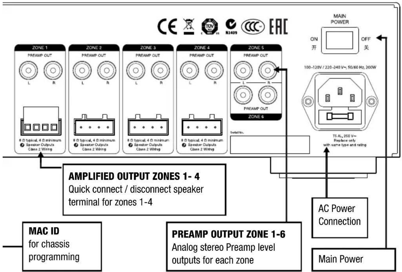
CHASSIS CONNECTIONS

flowchart
graph TD
    A["NILES. MODEL MRC-6430 Multi Room Controller"] --> B["SOURCE 1"]
    B --> C["IR OUT"]
    C --> D["AUDIO IN LOOP OUT L"]
    B --> E["SOURCE 2"]
    E --> F["AUDIO IN LOOP OUT R"]
    B --> G["SERVICE PORT"]
    G --> H["AUDIO IN LOOP OUT"]
    G --> I["IR OUT"]
    I --> J["AUDIO IN LOOP OUT"]
    G --> K["ETHERNET"]
    K --> L["AUDIO IN LOOP OUT"]
    G --> M["PAGE"]
    M --> N["AUDIO IN LOOP OUT"]

    subgraph SOURCE 1-6
        O["Analog source inputs with loop outputs"]
    end

    subgraph SOURCE 2
        P["IR OUT"]
        Q["IR OUT"]
        R["IR OUT"]
        S["IR OUT"]
        T["IR OUT"]
        U["IR OUT"]
        V["IR OUT"]
        W["IR OUT"]
        X["IR OUT"]
        Y["IR OUT"]
    end

    subgraph SERVICE PORT
        Z["For factory service only"]
        AA["Connect only Niles approved devices"]
    end

    subgraph ETHERNET
        AB["10/100 LAN connection"]
    end

    subgraph PAGE
        AC["Door bell or page input with loop output"]
    end

    AD["CAUTION AVIS SINGLE DOCC ELECTRICAL SET ARM CODE"] --> AE["MAC ID"]
flowchart
graph TD
    A["AC Power Connection"] --> B["Main Power"]
    C["MAC ID for chassis programming"] --> D["AMPLIFIED OUTPUT ZONES 1-4"]
    E["PREAMP OUTPUT ZONE 1-6"] --> F["Analog stereo Preamp level outputs for each zone"]
    G["MAIN POWER"] --> H["ON 开 OFF 关"]
    I["8.0 typical, 4.0 minimum Speaker Outputs Class 2 Wiring"] --> J["ZONE 1 PREAMP OUT L R"]
    K["8.0 typical, 4.0 minimum Speaker Outputs Class 2 Wiring"] --> L["ZONE 2 PREAMP OUT L R"]
    M["8.0 typical, 4.0 minimum Speaker Outputs Class 2 Wiring"] --> N["ZONE 3 PREAMP OUT L R"]
    O["8.0 typical, 4.0 minimum Speaker Outputs Class 2 Wiring"] --> P["ZONE 4 PREAMP OUT L R"]
    Q["8.0 typical, 4.0 minimum Speaker Outputs Class 2 Wiring"] --> R["ZONE 5 PREAMP OUT L R"]
    S["TS AL, 250 V~ Replace only with same type and rating"] --> T["Main Power"]
    U["100-120V / 220-240V~ 50/60 Hz, 200W"] --> V["MAIN POWER"]
    W["CE CE TUV N2409 CCC EAC"] --> X["Power Supply"]
    Y["MAC ID"] --> Z["Main Power"]
WHAT'S INCLUDED:
a. MRC-6430
b. 1ea US Power Cord
c. 1ea EU Power Cord
d. 4ea Removable Speaker Connectors
e. Quick Install Guide (this document)
f. 2ea Rack Mount Ears

MRC-6430
HOW TO BEGIN:
A Project Documentation Worksheet is included as part of this Install Guide. Documenting the project as you install it will greatly speed programming and ultimately enhance your experience. Save the Project Documentation Worksheet for future reference.
Determine the best location for the MRC-6430 and all audio source equipment (Media Streamer, Satellite, MP3 Player, etc).
Please follow key pad / touch panel wiring instructions included with those products.
Run speaker wiring (maximum 14 gauge) from each speaker location back to the MRC-6430.
Be sure to label all wires for easy documentation.
Turn off the Main Power switch to the MRC-6430 before making connections.
1. MOUNT IN CABINET OR RACK
Mount the MRC-6430 in a cabinet by setting it on a sturdy shelf. As with any electronic device the MRC-6430 generates heat at all times, but considerably more when all zones are playing. Ensure clear positive airflow within the cabinet by utilizing fans. Locating the MRC-6430 in a completely enclosed cabinet is not recommended due to heat build up.
Use the included rack mount ears and hardware to mount into a standard equipment rack. Use only the included screws to attach the ears to the MRC-6430. Ensure adequate ventilation for the MRC-6430 by placing at least one blank rack space above and below. If the rack is completely closed use positive ventilation to dissipate heat build up.
2. CONNECT TO NETWORK
With a category 5 (or higher) cable make a connection between the Ethernet port on the MRC-6430 and an open Ethernet port on the local area network. The MRC-6430 is defaulted for DHCP addressing. Static addressing is required when using a Niles HR200 and is set using the Auriel™ software wizard (see section 10).
Note the MAC ID in the Project Documentation Worksheet (extra sheet).

Niles HR200 - P/N: nHR200
3. CONNECT AUDIO SOURCES
A-SOURCES 1 THRU 6 CONNECTION
For audio sources with an analog audio output, connect the analog output to the MRC-6430 AUDIO IN with a stereo RCA cable.

flowchart
graph TD
    A["Source"] --> B["L"]
    A --> C["R"]
    B --> D["DATA INPUT"]
    C --> D
    D --> E["AUDIO IN"]
    D --> F["LOOP OUT"]
    E --> G["OUTPUT"]
    F --> H["OUTPUT"]
    I["SOURCE 1"] --> J["IR OUT"]
3. CONNECT AUDIO SOURCES
B - LOOP OUTPUTS 1 THRU 6 CONNECTION
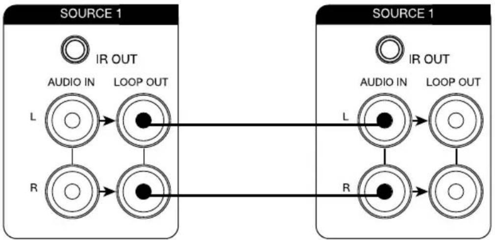
Two MRC-6430's may be used in a single system. This allows for 6 sources and up to 12 zones. The sources from chassis one are shared with chassis two by connecting the LOOP OUT from chassis one to the matching source AUDIO INPUT on chassis two.
flowchart
graph LR
    subgraph SOURCE 1
        A["IR OUT"] --> B["AUDIO IN"]
        B --> C["LOOP OUT"]
        D["L"] --> E["●"]
        F["R"] --> G["●"]
        H[" "] --> I[" "]
    end
    subgraph SOURCE 1
        J["IR OUT"] --> K["AUDIO IN"]
        K --> L["LOOP OUT"]
        M["L"] --> N["●"]
        O["R"] --> P["●"]
        Q[" "] --> R[" "]
    end
Master Chassis Extender Chassis
4. CONNECT DOORBELL INTERFACE (OPTIONAL)
Connect the AUDIO OUTPUT of the Niles DBI-2 Doorbell Interface to the PAGE AUDIO IN using an RCA male to male cable. If you are using an MRC-6430 Extender chassis, connect the PAGE LOOP OUT to the PAGE AUDIO IN on the Extender chassis.

flowchart
graph TD
    A["AUDIO IN"] --> B["LOOP OUT"]
    B --> C["To Extender Chassis"]
    D["Niles DBI-2 - P/N: FG01613"] --> E["DBI-2 - P/N: FG01613"]
5. CONNECT AND MOUNT IR EMITTERS
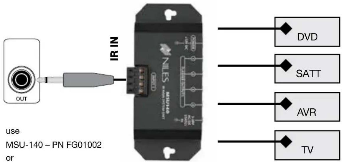
Connect the 3.5mm plug of each IR emitter into the designated port on the MRC-6430. The IR ports, labeled 1-6, are independently routed and may be used for any system device. Make sure to use the included System Worksheet to note which IR port is being used for each device. When using an additional MRC-6430 chassis to add zones 7 thru 12, the six IR outputs on the 2nd chassis are available as additional unique IR outputs.

When controlling media room system additional IR outputs may be necessary. IR outputs may be connected to a Niles IR Main System Unit (MSU-140, MSU-250, MSU-480) to expand IR outputs.
use
MSU-140 - PN FG01002
or
MSU-250 - PN FG01003
or
MSU-480 - PN FG01004
6. CONNECT SPEAKERS
SPEAKER CONNECTIONS 1 - 4
CAUTION! ALL SPEAKER WIRE CONNECTIONS MUST BE MADE WITH THE RECEIVER POWER OFF.
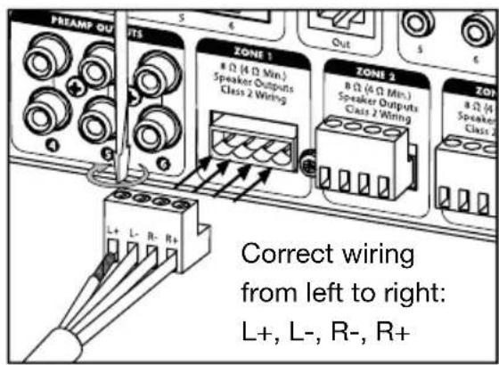
There are four sets of removable speaker wire terminals, one for each zone. The terminals accept speaker wires up to 14 AWG in size.
Each terminal has four screw-down connections for speaker wire:
one positive (+) and one negative (-) for each speaker. Unscrew the connection, insert the appropriate bare speaker wire, then tighten firmly.
If a speaker output is unterminated, the amplifier for that output is disabled by the power-on diagnostics. Should a speaker be connected later, the amplifier for that output will be enabled during the next power-on sequence.
7. ZONE PRE-AMP OUTPUTS
A - CONNECTING ZONE PRE-AMP OUTPUTS 1 THRU 6
Each zone of the MRC-6430 has a corresponding Zone Preamp Output to send signals to auxiliary amplifiers for powering more than 1 pair of speakers in a zone, powering speakers in zones 5 and 6, or adding additional power to a pair of speakers in a given zone.

flowchart
graph TD
    A["PREAMP OUT"] --> B["MAIN BUS INPUT"]
    A --> C["MAIN BUS OUTPUT"]
    D["ZONE 1"] --> E["Preamp Out"]
    F["L FOR BRIDGED MODE"] --> G["R"]
    H["L"] --> I["R"]
Niles SI series System Integration amplifier
7. ZONE PRE-AMP OUTPUTS
PRE-AMPS OUTPUTS 5 - 6 CONNECTION (optional use)
The pre-amp zone outputs on the MRC-6430 may be used to connect to an audio/video receiver for sharing the whole-house audio system's sources with a media room or home theater.

8. USB CONNECTION
The USB connection is for Niles approved accessories only. Please refer to the specific accessory's instruction manual for connection details. Do not plug any device not specifically approved and documented by Niles into the USB connection. Doing so may void the warranty.


Do not use USB-Memory-Sticks!
9. POWER UP THE MRC-6430
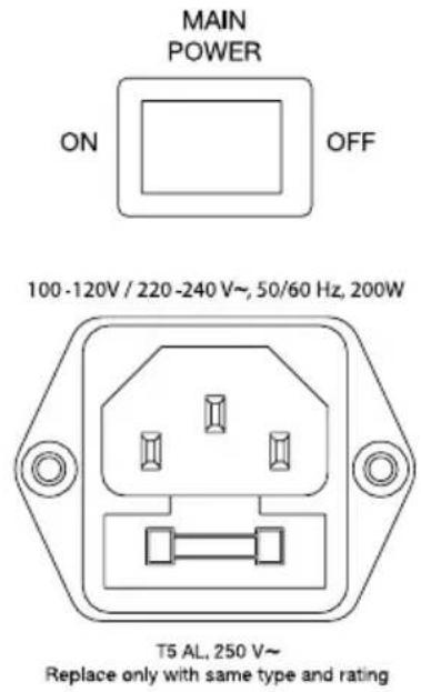
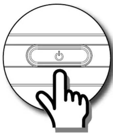
Plug in the MRC-6430 using the correct IEC power cord for your region. Engage the Main Power switch on the rear and press the Standby Power Button on the front to turn the unit on. When the MRC-6430 is in Standby mode, the button dims and the internal amplification and controller are shut down. In Standby mode the MRC-6430 will not respond to any external commands and will not provide any user interface screens. Activate the internal controller by pressing the Standby Power Button on the front panel.
natural_image
Icon of a hand pressing a button on a circular device with a power switch symbol (no text or labels)10. PROGRAMMING
Before programming please read the Auriel™ Wizard Programming Manual and watch the training videos, both of which may be found by visiting:
www.NilesAudio.com/AurielSupport
These assets should be checked with each new software release as features are added to the MRC-6430 regularly.
The Niles MRC-6430 is programmed using the wizard based Niles Auriel™ PC and MAC viewer found on the Niles website (www.nilesaudio.com), or the Niles Auriel™ App found on either the Android Play market or iTunes app store.


11. SPECIFICATIONS
| Dimensions 17 1/4”W x 4 | 15/16”H x 12 7/8”D with feet(437 x 100 x 328 mm)Rackmount dimensions:17 1/4”W x 3 1/2”H (2U) x 12 7/8”D without feet(437 x 88 x 328 mm) |
| Weight 18 lbs. (8,6 kg) | |
| Power Supply 100-120 / 2 | 20-240 V~, 50 / 60 Hz |
| Fuse Rating T5 AL, 250 V~ | |
| Power Consumption - While operating – 200 W maximum- While power is off – 0.0 W- In Standby mode – 0.3 W- In Networked Standby mode – 1.6 Wo The unit will automatically switch intoStandby or Networked. Standby mode after15 minutes with no audio input. | |
| Amplifier Power Output 30 | watts/ch @ 8Ω45 watts/ch @ 4Ω |
| THD <0.10%, 1 watt output into 8Ω | |
| Signal to Noise Ratio >100db, 20Hz-20kHz unweighted | |
| Audio Source Inputs 6 – analog, RCA connectors | |
| Audio Zone Outputs 6 – 4 | Amp + Preamp, 2 Preamp Only |
| Speaker Connections (4) | detachable, (4) pole terminals |
| IR Outputs 6 routable | |
| Ethernet 1 RJ-45 10/100 | BaseT |
| USB 1 Type-A | |
LIMITED WARRANTY
Core Brands, LLC (“Core Brands”) warrants to the original retail purchaser only that this product will be free of manufacturing defects in material and workmanship for the following periods and subject to the limitations and exclusions set forth below:
Lifetime Warranty
All Passive Amplifier Products (those not requiring AC or battery power).
Ten years from the date of purchase
All Other Passive Products (those not requiring AC or battery power).
Two years from the date of purchase
All Active Products (those requiring AC or battery power).
This warranty is not transferable to subsequent purchasers of the product. To obtain warranty service, contact the authorized dealer where you purchased your product or take the unit to the nearest authorized Niles dealer (with proof of purchase – claims made without proof of purchase will be denied) who will test the product and if necessary, forward it to Core Brands for service. If there are no authorized Niles dealers in your area, you must contact Core Brands to receive a factory Return Authorization Number. DO NOT RETURN ANY UNIT WITHOUT FIRST RECEIVING WRITTEN AUTHORIZATION AND SHIPPING INSTRUCTIONS FROM CORE BRANDS.
Upon examination, Core Brands will, at its sole option and expense, repair or replace any product found to be defective. Core Brands will return the repaired or replaced unit to you via its usual shipping method from the factory to your address in the United States of America or Canada only. Any shipping costs for addresses outside of the United States or Canada shall be the responsibility of the purchaser. In the event that this model is no longer available and cannot be repaired effectively, Core Brands, at its sole option, may replace it with a different model of equal or greater value, or refund the original purchase price paid. THE FOREGOING ARE YOUR EXCLUSIVE REMEDIES FOR BREACH OF WARRANTY.
This Warranty does not include service or parts to repair damage caused by improper use or handling, including but not limited to damage caused by accident, mishandling, improper installation, commercial use, abuse, negligence, or normal wear and tear, or any defect caused by repair to the product by anyone other than Core Brands.
This warranty does not cover reimbursement for your costs of removing and transporting the product for warranty service evaluation, or installation of any replacement product provided under this warranty.
This Warranty will be void if:
- the Serial Number on the product has been removed, tampered with or defaced.
- the product was not purchased from an authorized dealer or reseller.
THE FOREGOING WARRANTIES ARE EXCLUSIVE AND IN LIEU OF ALL OTHER EXPRESSED AND IMPLIED WARRANTIES. CORE BRANDS EXPRESSLY DISCLAIMS ALL SUCH OTHER WARRANTIES, INCLUDING BUT NOT LIMITED TO IMPLIED WARRANTIES OF MERCHANTABILITY, FITNESS FOR A PARTICULAR PURPOSE AND NON-INFRINGEMENT, WITH RESPECT TO THE PRODUCT. TO THE MAXIMUM EXTENT PERMITTED BY LAW, CORE BRANDS SHALL NOT BE RESPONSIBLE FOR ANY INCIDENTAL OR CONSEQUENTIAL DAMAGES EXCEPT TO THE EXTENT PROVIDED (OR PROHIBITED) BY APPLICABLE LAW, EVEN IF CORE BRANDS HAS BEEN ADVISED OF THE POSSIBILITY OF SUCH DAMAGES.
Notwithstanding the above, if you qualify as a “consumer” under the Magnuson-Moss Warranty Act, or applicable state laws, then you may be entitled to any implied warranties allowed by law for the Warranty Period. Further, some states do not allow limitations on how long an implied warranty lasts or allow the exclusion or limitation of consequential damages, so such limitations may not apply to you. This warranty gives you specific legal rights, and you may also have other rights which vary from state to state.
For the name of your nearest authorized NILES dealer, contact: Core Brands, LLC, 1800 South McDowell Blvd, Petaluma, CA 94954, or call (800) BUY-HIFI (289-4434) or (707) 778-5733. Please be advised that NILES only sells its products via the Internet through a select group of authorized Internet dealers. These are listed on our website at www.nilesaudio.com. Products offered on the Internet through unauthorized Internet dealers are not covered by the NILES / Core Brands warranty and may be either:
1) goods acquired on a secondary or grey market
2) counterfeit or stolen goods
3) damaged, or defective goods
Please fill in your product information and retain for your records.
Model
Serial No.
Purchase Date
ATTENTION: TO OUR VALUED CONSUMERS:
To insure that consumers obtain quality pre-sale and after-sale support and service, NILES products are sold exclusively through authorized dealers. This warranty is VOID if the products have been purchased from an unauthorized dealer.

NILES®
HOME OF ENTERTAINMENT INNOVATION
1800 South McDowell Blvd, Petaluma, CA 94954
1 - 7 0 7 - 7 7 8 - 5 7 3 3
1-800-BUY-HIFI - www.nilesaudio.com
©2014 Core Brands, LLC. All rights reserved. Niles® and Auriel® are registered trademarks of CoreBrands, LLC, a Nortek company. All other trademarks are the property of their respective owners. We reserve the right to change specifications, descriptions and prices without notice. The technical and other information contained herein is not intended to set forth all technical and other specifications. Designed and engineered in the USA. 9901342 Rev B
12. PROJECT DOCUMENTATION WORKSHEET
Network
| DHCP-Range | |
| Sub-Net Mask | |
| Gateway | |
| Wireless SSID | |
| Passkey |
| Unit 1 IP Address | |
| Unit 1 MAC Address |
NOTES
Sources Name
| 1 | |
| 2 | |
| 3 | |
| 4 | |
| 5 | |
| 6 |
| Unit 2 IP Address | |||
| Unit 2 MAC Address |
| Misc Network Device IP Address | ||
| Misc Network Device IP Address | ||
| Misc Network Device IP Address | ||
| Misc Network Device IP Address | ||
| Misc Network Device IP Address |
PRIMARY CHASIS SECONDARY CHASIS
(for expansion)
IR Outputs Unit 1
| 1 | |
| 2 | |
| 3 | |
| 4 | |
| 5 | |
| 6 |
IR Outputs Unit 2Name Name
| 1 | |
| 2 | |
| 3 | |
| 4 | |
| 5 | |
| 6 |
PRIMARY CHASISSECONDARY CHASIS (for expansion)
12. PROJECT DOCUMENTATION WORKSHEET
| Zones Name Amplifier Channels | ||
| 1 | ||
| 2 | ||
| 3 | ||
| 4 | ||
| 5 | ||
| 6 | ||
| 7 | ||
| 8 | ||
| 9 | ||
| 10 | ||
| 11 | ||
| 12 | ||
Speakers User Interface
| MAC Address | |||
| MAC Address | |||
| MAC Address | |||
| MAC Address | |||
| MAC Address | |||
| MAC Address | |||
| MAC Address | |||
| MAC Address | |||
| MAC Address | |||
| MAC Address | |||
| MAC Address | |||
| MAC Address | |||
| MAC Address | |||
| MAC Address | |||
| MAC Address | |||
| MAC Address | |||
| MAC Address | |||
| IP Address | |||
| MAC Address | |||
| IP Address | |||
| MAC Address |


- Multi Room Controller
- MRC-6430
- CONGRATULATIONS!
- IMPORTANT SAFETY INSTRUCTIONS
- FCC Required Text:
- OVERVIEW MRC-6430
- CHASSIS CONNECTIONS
- WHAT'S INCLUDED:
- HOW TO BEGIN:
- MOUNT IN CABINET OR RACK
- CONNECT TO NETWORK
- CONNECT AUDIO SOURCES
- A-SOURCES 1 THRU 6 CONNECTION
- B - LOOP OUTPUTS 1 THRU 6 CONNECTION
- CONNECT DOORBELL INTERFACE (OPTIONAL)
- CONNECT AND MOUNT IR EMITTERS
- CONNECT SPEAKERS
- SPEAKER CONNECTIONS 1 - 4
- Each terminal has four screw-down connections for speaker wire:
- ZONE PRE-AMP OUTPUTS
- A - CONNECTING ZONE PRE-AMP OUTPUTS 1 THRU 6
- PRE-AMPS OUTPUTS 5 - 6 CONNECTION (optional use)
- USB CONNECTION
- POWER UP THE MRC-6430
- PROGRAMMING
- www.NilesAudio.com/AurielSupport
- SPECIFICATIONS
- LIMITED WARRANTY
- ATTENTION: TO OUR VALUED CONSUMERS:
- NILES®
- PROJECT DOCUMENTATION WORKSHEET
Brand : Niles
Model : MRC-6430
Category : Receiver