
SI-1230 Series 2 - Receiver Niles - Free user manual and instructions
Find the device manual for free SI-1230 Series 2 Niles in PDF.


| Product Type | 12-Channel Power Amplifier |
| Power Output (8 ohms) | 30 watts RMS per channel, all channels driven |
| Power Output (4 ohms) | 40 watts RMS per channel, all channels driven |
| Bridged Power Output (8 ohms) | 80 watts RMS per channel |
| Frequency Response | 5 Hz – 25 kHz, +0/-3 dB |
| Signal-to-Noise Ratio | >102 dB (unweighted, 20 Hz – 20 kHz) |
| Total Harmonic Distortion | <0.05% @ 1 kHz |
| Channel Separation | >70 dB @ 1 kHz |
| Number of Channels | 12 (6 bridgeable pairs) |
| Inputs | Gold-plated RCA jacks (12 dedicated, plus Main Bus L/R) |
| Outputs | 5-way binding posts, dual banana spacing |
| BusMatrix™ Switching | Assign each channel to Left, Right, Mono bus, or dedicated input |
| Bridging | Slide switch per pair to combine two channels (8 ohms min) |
| Turn-On Modes | Constant, Audio Sense, 3-30V AC/DC Trigger |
| Protection | Per-channel thermal and short circuit protection with status LEDs |
| Dimensions (W x H x D) | 17.25 x 5.75 x 16.25 inches (43.8 x 14.6 x 41.3 cm) |
| Weight | 35 lb (15.9 kg) |
| Power Requirements | 100-120 / 220-240 V~, 50/60 Hz, 500W max |
| Warranty | Limited 2 years parts and labor (active products) |
| Cleaning | Dry cloth only; no spray or abrasive cleaners |
Frequently Asked Questions - SI-1230 Series 2 Niles
User questions about SI-1230 Series 2 Niles
0 question about this device. Answer the ones you know or ask your own.
Ask a new question about this device
Download the instructions for your Receiver in PDF format for free! Find your manual SI-1230 Series 2 - Niles and take your electronic device back in hand. On this page are published all the documents necessary for the use of your device. SI-1230 Series 2 by Niles.
USER MANUAL SI-1230 Series 2 Niles
CONGRATULATIONS!
Thank you for purchasing the award winning Niles SI-1230 Series 2, one of the most versatile and powerful multi-channel amplifiers ever offered. Like all Niles products, the SI-1230 is built to the highest standards of quality and reliability. With proper installation and operation, you'll enjoy years of trouble-free use.
TABLE OF CONTENTS
| INTRODUCTION | 4 |
| FEATURES AND BENEFITS | 5 |
| SYSTEM DESIGN BASICS | 7 |
| SYSTEM DESIGN CONSIDERATIONS 9 | |
| APPLICATIONS | 11 |
| CONFIGURING YOUR SYSTEM | 15 |
| INSTALLATION CONSIDERATIONS | 16 |
| FRONT AND REAR PANEL DETAILS | 18 |
| INSTALLATION | 20 |
| OPERATION | 25 |
| TROUBLESHOOTING GUIDE | 27 |
| SPECIFICATIONS | 29 |
| CONFIGURATION WORKSHEET | 30 |
IMPORTANT SAFETY INSTRUCTIONS
-
Read these instructions.
-
Keep these instructions.
-
Heed all warnings.
-
Follow all instructions.
-
Do not use this apparatus near water.
-
Clean only with a dry cloth.
-
Do not block any ventilation openings. Install in accordance with the manufacturer's instructions.
-
Do not install near any heat sources such as radiators, heat registers, stoves or other apparatus (including amplifiers) that produce heat.
-
Do not defeat the safety purpose of the polarized or grounding-type plug. A polarized plug has two blades with one wider than the other. A grounding-type plug has two blades and a third grounding prong. The wide blade or the third prong is provided for your safety. If the provided plug does not fit into your outlet, consult an electrician for replacement of the obsolete outlet.
-
Protect the power cord from being walked on or pinched, particularly at plugs, convenience receptacles and the point where they exit from the apparatus.
-
Only use attachments/accessories specified by the manufacturer.
-
Use only with the cart, stand, tripod, bracket or table specified by the manufacturer or sold with the apparatus. When a cart is used, use caution when moving the cart/apparatus combination to avoid injury from tip-over.

-
Unplug this apparatus during lightning storms or when unused for long periods of time.
-
Refer all servicing to qualified service personnel. Servicing is required when the apparatus has been damaged in any way, such as power supply cord or plug is damaged, liquid has been spilled or objects have fallen into the apparatus, the apparatus has been exposed to rain or moisture, does not operate normally, or has been dropped.
-
Do not expose this apparatus to dripping or splashing and ensure that no objects filled with liquids, such as vases, are placed on the apparatus.
-
To completely disconnect this apparatus from the AC Mains, disconnect the power supply cord plug from the AC receptacle.
-
The power supply cord (sometimes referred to as the "Mains Plug") is used as the disconnect device and shall remain accessible and operable at all times.
-
Do not expose batteries to excessive heat such as sunshine, fire or the like.
-
Open flame sources, such as lighted candles, should NOT be placed on the apparatus.
WARNING: To reduce the risk of fire or electric shock, do not expose this apparatus to rain or moisture.

The lightning flash with arrowhead symbol, within an equilateral triangle, is intended to alert the user to the presence of uninsulated “dangerous voltage” within the product’s enclosure
that may be of sufficient magnitude to constitute a risk of electric shock to persons.

The exclamation point within an equilateral triangle is intended to alert the user to the presence of important operating and maintenance (servicing)
instructions in the literature accompanying the product.
FCC Required Text:
NOTE: This equipment has been tested and found to comply with the limits for a Class B digital device, pursuant to part 15 of the FCC Rules. These limits are designed to provide reasonable protection against harmful interference in a residential installation. This equipment generates, uses, and can radiate, radio frequency energy and, if not installed and used in accordance with the instructions, may cause harmful interference to radio communications. However, there is no guarantee that interference will not occur in a particular installation. If this equipment does cause harmful interference to radio or television reception, which can be determined by turning the equipment off and on, the user is encouraged to try to correct the interference by one or more of the following measures:
—Reorient or relocate the receiving antenna.
—Increase the separation between the equipment and receiver.
—Connect the equipment into an outlet on a circuit different from that to which the receiver is connected.
—Consult the dealer or an experienced radio/TV technician for help.
Changes or modifications not expressly approved by the party responsible for compliance could void the user's authority to operate the equipment.
INTRODUCTION
We call the SI-1230 a Systems Integration Amplifier because it is a power amplifier specifically designed to solve the problems of interfacing with different brands and models of equipment, different acoustic environments in different rooms, and different kinds of applications: home theater, stereo, and background music. As you read this manual and become more familiar with the capabilities of the SI-1230 you’ll understand why its predecessor, the SI-1200, was selected Best New Product 1994 by Sound & Video Contractor Magazine and CEDIA (Custom Electronic Design and Installation Association). In addition, the SI-1200 also won the Consumer Electronics Show’s Innovations ‘95 Design and Engineering Award.
BRIDGABLE POWER AMPLIFIERS

SI-1230 SeRieS 2
FEATURES AND BENEFITS
REAL WORLD POWER
The SI-1230 is a 12-channel amplifier that delivers a solid 30 watts per channel RMS into 8 ohms and 40 watts per channel RMS into 4 ohms. A new digital power transformer design provides the energy necessary to efficiently deliver solid, deep, controlled bass response to a house full of speakers.
TWELVE TO SIX CHANNEL CONFIGURABLE POWER
Each of the SI-1230's six adjacent speaker output pairs are bridgeable. You can create up to six 80 watt channels by sliding the bridging switches located between each pair to the “bridged” position. This enables you to allocate more power to specific locations, such as large rooms or outdoor applications.
FREEDOM FROM NOISE AND CROSS-TALK
The SI-1230's BusMatrix™ incorporates advanced PCB construction ensuring extremely high channel to channel isolation. Signal to noise ratios and cross-talk are equivalent to a professional mixing board found in a recording studio. With the SI-1230, the music playing in the living room cannot interfere with the music in the den.
TRANSPARENT SOUND
The audio circuitry of the SI-1230 is constructed with the finest parts available, including 1% metal film resistors, high quality capacitors and oversized heat sinks. All this attention to technical detail results in a sound that is clear and uncolored.
BUSMATRIX™ SELECTOR
Our unique BusMatrix ™ selector gives you the flexibility to assign each channel to a common Left, Right, or Mono signal bus, or to a dedicated signal input. With BusMatrix ™ , routing surround sound to the master bedroom, stereo to the den and mono to the powder room is as simple as flicking a switch. BusMatrix ™ makes the SI-1230 an ideal multi-room or multi-zone amplifier and offers exciting new features and system design possibilities to the professional installer.
FEATURES AND BENEFITS CONTINUED...
INDEPENDENT LEVEL CONTROLS
Each amplifier channel has an independent level control enabling you to adjust the volume settings for twelve different speaker locations individually. Each speaker can now be adjusted specifically for its location and for who will be listening!
TURN-ON MODES
The SI-1230 features three turn-on modes: 1. Manual turn-on via the front panel switch, 2. Audio Sense and 3. External Voltage trigger. Audio Sense and External Voltage trigger modes enable you to configure the SI-1230 to interface with any kind of system and turn on automatically.
AUTOMATIC PROTECTION
Each channel has independent thermal and short circuit protection. In the unlikely event that a problem occurs on one channel, the other channels will continue to play. When conditions return to normal, regular operation resumes.
STATUS DISPLAY FOR TROUBLESHOOTING
LED's on the front panel indicate Power, Active and Protection Status. With a glance at the frontpanel a troubleshooter is quickly provided with key information!
DESIGNED AND ENGINEERED IN THE USA
Limited two-year parts and labor warranty.
SYSTEM DESIGN BASICS
As shown in Figure 1, a distributed audio/video system is defined by the number of listening zones it has. Within a listening zone you can listen to only one source (e.g. CD, Radio, iPod, etc.) at any one time. A listening zone can consist of a single room or a group of rooms. To achieve different volumes and greater convenience in different rooms within a zone, individual volume controls can be used. Niles makes volume controls in various styles and colors. When designing your system, take into account who will use the system and when they will use it. Consult your local Niles dealer for more information.
Figure 1
![graph TD A["Blu-ray Player"] --> D["RECEIVER"] B["CD Player"] --> D C["Cable Box"] --> D E["Plasma/LCD"] --> D D --> F["Family Room L"] D --> G["Speaker 1"] D --> H["Speaker 2"] D --> I["Speaker 3"] D --> J["Speaker 4"]](/content/2026/05/948984/images/ac15b3c02bf3b6752d39f4995454b3c06137748da9dde5e2853cd1d45a29effb.jpg)
Listening Zone 1
SYSTEM DESIGN BASICS CONTINUED...
A MultiZone system as shown in Figure 2, offers the house hold more flexibility. For instance, a family might have their family room wired for surround sound and their living room wired for background music. In a two zone system, the children can watch TV in surround sound while Mom and Dad are reading the paper and enjoying background music in the living room.
Figure 2
![graph TD subgraph Family Room A["Blu-ray Player"] --> B["RECEIVER"] C["CD Player"] --> B D["Cable Box"] --> B E["Plasma/LCD"] --> B end subgraph Living Room F["Speaker 1"] --> G["Receiver"] H["Speaker 2"] --> I["Receiver"] J["Speaker 3"] --> K["Receiver"] end B --> I B --> K style Family Room fill:#…](/content/2026/05/948984/images/5e85aaaf74a2871a021c06588496cf7ddbf610a9f418f9eca3ebf0c35815c1c0.jpg)
SYSTEM DESIGN CONSIDERATIONS
SPEAKER COMPATIBILITY
A single channel (not bridged) of the SI-1230 is capable of driving a 4 ohm impedance speaker load. No more than two 8 ohm speakers or no more than one 4-6 ohm speaker can be safely connected to a single channel. Proper ventilation of the SI-1230 is critical when driving lower impedance loads. If the SI-1230 is not properly ventilated, the protection circuits may activate and shut off the channel at higher volume levels (for more information on proper amplifier placement, see Installation Considerations on page 15).
A channel pair that has been BRIDGED is capable of driving an impedance load of 8 ohms. Proper ventilation of the SI-1230 is critical when driving a 8 ohm load with bridged channels. If the SI-1230 is not properly ventilated, the protection circuits may activate and shut off the channel at higher volume levels (for more information on proper amplifier placement, see Installation Considerations on page 15).
When designing your system, try to specify 6-8 ohm speakers (Niles offers a complete line of inwall, in-ceiling, outdoor and home theater loudspeakers with all models rated from 6-8 ohms).
CABLE AND WIRE
Because the SI-1230 has many connections on the rear panel (see Figure 12), it is important that you correctly label all of the input cables and speaker wires. Label the cables and wires with their destination or source, rather than the SI-1230 terminal to which they are connected. This will make it easier to reconfigure your system in the future.
The SI-1230 connects to your sources via shielded line level audio cables with RCA connectors. Use high quality cables with your Niles amplifier for the lowest possible noise and best overall performance. Your Niles dealer can recommend the proper cable.
The SI-1230 connects to your speakers using two conductor speaker wire. For most applications, we recommend you use 16 or 18 gauge wire. For wiring runs longer than 80 feet, we recommend 14 gauge wire. The SI-1230's high-quality, gold-plated 5-way binding posts will accommodate up to 12-gauge wire. Attaching banana plugs to the wire will enable the connection of larger wire sizes.
SYSTEM DESIGN CONSIDERATIONS CONTINUED...
USING MONO FOR SMOOTHER COVERAGE
In large or irregularly shaped rooms, you may find that the main listening area may be closer to one of the speakers. If the speakers in the room are connected to a stereo amplifier you will only hear half the music. The SI-1230's BusMatrix™ enables you to create mono sound from one speaker without impacting the stereo quality in the rest of the system. You can configure each room to either stereo or mono as needed with no ill effects. Some of the most popular areas where mono will greatly enhance the sound quality would be:
• Large rooms with many seating areas and/or many pairs of speakers.
- Irregularly shaped rooms.
- Bathrooms with one speaker over the tub and one speaker over the sink(s).
• Hallways or passageways (including those with multiple speakers).
- Small rooms, such as walk-in closets where more than a single speaker is not required.
BRIDGING CHANNELS FOR AREASTHAT REQUIRE MORE VOLUME AND POWER
There are several situations where bridging is an excellent way to improve the sound. There are also applications where bridging would seem to be appropriate but is not recommended. Bridging channels increases the power output to 80 watts per channel at 8 ohms.
These are some of the most common DOs and DON'Ts:
-
Outdoors (DO) — Sound dissipates faster outside than it does in a room where the walls enclose the sound and reflect it back to the listener. A pair of speakers playing into a large patio or yard will greatly benefit from bridging four channels into two 80 watt channels.
-
Surround Sound Systems (DO) — The dynamic demands for the center channel are much greater than the left, right or surround channels. This is an excellent application for two channels to be bridged into one 80 watt channel.
-
More than one pair of 8 ohm speakers (DON'T) — In a large room or a long hallway, often the best way to get good background music is to install multiple pairs of speakers. You will actually deliver more power to two pairs of 8 ohm speakers by using two unbridged amplifier channels than you would if you bridged four amplifier channels into two and connected the two pairs of speakers in parallel.
APPLICATIONS
ADVANTAGES OF USING THE SI-1230 IN A SINGLE ZONE SYSTEM
When you connect the preamplifier outputs of your stereo receiver or stereo preamplifier to the SI-1230 BusMatrix™ you dedicate a robust 30 watts to each speaker in your multi-room system as shown in Figure 3.
Each channel of the SI-1230 has its own level control so you can compensate for architectural differences that create sonic imbalances. In addition, you can fine tune the system so that when all of the room volume controls are set to the loudest level, the large rooms and the small rooms play at the same volume.
Figure 3
![graph TD A["Blu-ray Player"] --> D["SI-1230 SERIES 2"] B["CD Player"] --> D C["Cable Box"] --> D D --> E["NILES"] style D fill:#f9f,stroke:#333 style E fill:#ccf,stroke:#333 note right of D PRE-AMP or AM/FM RECEIVER note right of D Single Zone](/content/2026/05/948984/images/88cde192ec6f8707b059c24561a75f2033ec455d8905fb601836cc8fe60fe22c.jpg)
APPLICATIONS
USING A DUAL-ZONE RECEIVER FOR TWO LISTENING ZONES
Most of today's Dolby Digital Audio Video Receivers include a second zone preamplifier output to create a second listening zone. Using this output with the SI-1230 BusMatrix™ input provides amplification for multiple rooms within a second listening zone as shown in Figure 4.
In addition, in this example high power is supplied to the patio stereo speakers by bridging channel pair 9 and 10 for the left speaker and bridging channel pair 11 and 12 for the right speaker.
Figure 4
![graph TD A["Blu-ray Player"] --> D["DUAL-ZONE SURROUND SOUND RECEIVER"] B["CD Player"] --> D C["Cable Box"] --> D D --> E["SI-1230 SERIES 2"] E --> F["BusMatrix™"] E --> G["Niles High Power Volume Controls"] E --> H["Living Room Kitchen Office Bedroom Patio"] E --> I["(Bridged Channels 9-10, 11-12)"…](/content/2026/05/948984/images/eab5d470a2fcb05d30228f66952eb33fe368bb94279b24153cdda290335ec561.jpg)
APPLICATIONS
EXPANDING A MULTIZONE SYSTEM TO INCLUDE MORE ROOMS
In the ultimate MultiZone system, you connect six stereo preamplifiers (or a single component multi-zone/multi-source preamplifier) to the dedicated inputs of SI-1230. These dedicated input signals are then routed to the appropriate amplifier channels via dip switch settings creating six completely independent listening zones.
MultiZone systems enable listeners located in the six separate zones to simultaneously listen to different source components as shown in Figure 5.
Figure 5
![graph TD A["Blu-ray Player"] --> B["Niles ZR-6 MultiZone Receiver"] C["CD Player"] --> B D["Cable Box"] --> B B --> E["BusMatrix™"] E --> F["Room 1"] E --> G["Room 2"] E --> H["Room 3"] E --> I["Room 4"] E --> J["Room 5"] B --> K["Zone 1 - 5 Speaker Outputs"] K --> L["Room 1"] K --> M["Room 2"] K --…](/content/2026/05/948984/images/7d4b068b4b8f3a6288b17818346a40a13d27ce71d33cdb94928000e0d3a54b1e.jpg)
APPLICATIONS
ADDING PREAMPS TO CREATE MORE LISTENING ZONES
In the ultimate MultiZone system, you connect six stereo preamplifiers (or a single component multi-zone/multi-source preamplifier) to the dedicated inputs of SI-1230. These dedicated input signals are then routed to the appropriate amplifier channels via dip switch settings creating six completely independent listening zones.
MultiZone systems enable listeners located in the six separate zones to simultaneously listen to different source components as shown in Figure 6.
Figure 6
![graph TD A["Blu-ray Player"] --> B["Matrix Switching Preamp"] C["CD Player"] --> B D["Cable Box"] --> B B --> E["SI-1230 SERIES 2"] E --> F["Zone 1"] E --> G["Zone 2"] E --> H["Zone 3"] E --> I["Zone 4"] E --> J["Zone 5"] E --> K["Zone 6"] B --> L["Zone Outputs"] B --> M["Dedicated Inputs"]](/content/2026/05/948984/images/6b7fefcb18ea0516c92a73478e78c549af813b211011a323ed526051f63ed282.jpg)
CONFIGURING YOUR SYSTEM
Because the SI-1230 offers so many configuration possibilities it is important to plan carefully before you install it. Draw a block diagram of your system and use the Configuration Worksheet on page 27 to record how you plan to connect your SI-1230.
Here is an example filled out according to the block diagram on page 10.
Example 1
| BUS INS & OUTS CONNECTED TO | |
| Left Main Bus | Stereo Receiver - 2nd Zone - Left Pre-Output |
| Right Main Bus | Stereo Receiver - 2nd Zone - Right Pre-Output |
| Cascade Output | |
| CH# | BRIDGED | DIP | INPUT SOURCE SPEAKER | |
| 1 | L Main Bus Zone1 - Left | |||
| 2 | R Main Bus Zone1 - Right | |||
| 3 | L Main Bus Zone2 - Left | |||
| 4 | R Main Bus Zone2 - Right | |||
| 5 | L Main Bus Zone3 - Left | |||
| 6 | R Main Bus Zone3 - Right | |||
| 7 | L Main Bus Zone4 - Left | |||
| 8 | R Main Bus Zone4 - Right | |||
| 9 | ||||
| 10 | L Main Bus Zone5 - Left | |||
| 11 | ||||
| 12 | R Main Bus Zone5 - Right | |||
| MODE SETTINGS IN USE SPECIAL | ||
| Constant | ||
| Audio Sense | ||
| Voltage Trigger | ||
| Control Output | ||
INSTALLATION CONSIDERATIONS
Automating the turn-on of your SI-1230 is one of the easiest steps when installing it in a distributed system. However, do not plug the main power cord into the switched AC outlet of your preamplifier or receiver. The high power design of the SI-1230 requires large amounts of current from its AC power source. Additionally, it is always recommended to activate the system preamplifier/receiver before turning on your SI-1230 in order to prevent system “turn-on thumps”. In order to address these important needs, the SI-1230 has three special turn-on modes that let you turn the amplifier on only when it is needed. These three options are accessed by the Turn-On Mode selector switch (see Figure 7).
Turn-On Modes
Constant – The auto turn-on circuitry is off. The front panel master power switch operates the amplifier. In is “On”, Out is “Off”.
Audio Sense – The master switch on the front panel must be in the “On” position. The amplifier is off when there is no audio signal present at any of the audio inputs, but the sensing circuitry is on. The turn-on sensing circuitry looks for a signal present at any of the audio inputs. If it detects a signal, the adjacent pair of amplifier channels (i.e. channel 1 & 2, 3 & 4, etc.) assigned to receive the input signals will turn on. Once the audio signal stops, the sensing circuit waits two minutes, then turns all amplifier channels off.
Figure 7
TURN ON MODE
![AUDIO SENSE CONSTANT —— [ ] —— 3-30V AC/DC TRIGGER INPUT](/content/2026/05/948984/images/87387d3534c2094eeed339371e727a9f6213aa41eef7bbd79c5e0c14de6076fb.jpg)
ImportTanT! The FronT Panel Power SwiTch muST be in The on (SwiTch in) PoSiTion For any oF The Three Turn-on oPTionS To FuncTion
3-24 Volt Ac/Dc Opto-Isolated Voltage Trigger - The Power switch on the front panel must be in the “On” position for the voltage trigger to function. When a Trigger Plug is inserted into the rear panel connector and the sensing circuitry detects a voltage, the amplifier is turned on. Once the Trigger voltage is turned off, the sensing circuit instantly turns the amplifier off. The amplifier is off when there is no 3-24V AC or DC voltage detected at the trigger input. Voltage triggers can be supplied by Niles automated switchers, some video projectors, some surround sound processors, or something as simple as a 12 volt AC wall adapter plugged into the switched outlet of your stereo receiver. Linear DC wall adapters are not recommended; the long discharge time of the DC adapter’s filter capacitor will delay the turn-off of the amplifier. Trigger sources must be 3-24VAC or DC, 20mA or greater.
INSTALLATION CONSIDERATIONS
PLACEMENT
Place the SI-1230 on a flat, level surface like a table or shelf. It should be placed upright so that its weight rests on the unit's four feet. PLACING THE WEIGHT OF THE AMPLIFIER ON THE REAR OR FRONT PANEL FOR EVEN AN INSTANT WILL RESULT IN DAMAGE TO THE AMPLIFIER'S CONNECTORS AND CONTROLS.
The SI-1230, like any hi-fi component, will last much longer if it is given adequate ventilation for proper cooling. When installing the SI-1230 in a cabinet, be sure that the rear of the cabinet is open to fresh air to provide proper cooling (see Figure 10). If the cabinet's design will not accommodate an open rear, install two small "boxer fans" to provide continuous air flow into and out of the cabinet (see Figure 11). Place the SI-1230 so that there is at least 5" of free air space above the chassis. If the amplifier is located on a carpeted surface, place a board under the amplifier's feet. Do not block the ventilation holes on the top and bottom of the SI-1230.
The SI-1230 is equipped with a digital power transformer. This transformer generates a powerful magnetic field which could induce hum in a turntable (particularly a turntable equipped with a moving coil cartridge). Do not place a turntable directly above or directly adjacent to the SI-1230.

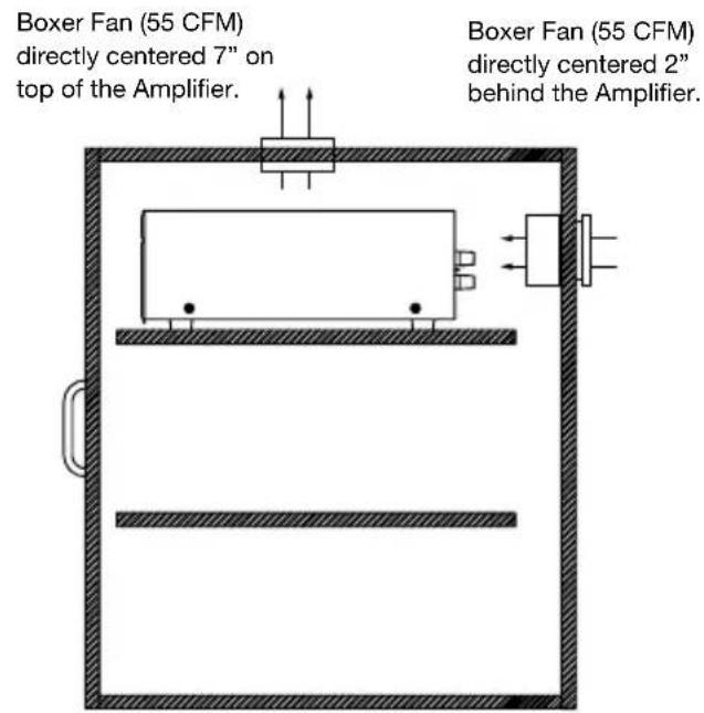
If the cabinet rear is not open to fresh air or if you're using low impedance loads, install two "boxer fans" to provide continuous air flow into and out of the cabinet.
FRONT AND REAR PANEL DETAILS
Main Bus Inputs enable you to route a stereo line level source to the BusMatrix™ of the SI-1230
Cascade outputs of the main bus input enable you to daisy chain multiple amplifiers

FRONT AND REAR PANEL DETAILS

NILES.
Power LED illuminates to confirm the amplifier is connected to a live AC power outlet and that the master power switch is on
STATUS
Bicolor Status LED illuminates "green" when the amplifier circuitry has been turned on by the Turn-On circuits, and illuminates "red" to indicate activation of the amplifier's built-in protection circuitry
[Non-Text]
Bridging switches, BusMatrix controls, dedicated inputs and level controls for each channel

INSTALLATION
LINE LEVEL AUDIO INPUT
CAuTION! The amplifier must be off whenever you make changes to the input connections.
| STEp DESCrlpTlon | |
| 1. Label all of the interconnecting cables for the sources they connect to. | Use audio patch cables with RCA phono plugs attached to the ends. |
| 2. Connect the sources by inserting the RCA plug into the amplifier's jacks. NOTE: If you are using two amplifier channels in “bridged” mode connect the input cable to the even numbered amplifier input jack. | Connect outputs from your sources to inputs on the amplifier. Never connect a source or preamplifier's input (e.g., record inputs) to the inputs of your SI-1230. |
CASCADE AUDIO OUTPUTS
The “Cascade Audio Outputs” enable you to connect another amplifier to your preamplifier output. The connectors are gold-plated RCA phono jacks. Connect them to another amplifier’s inputs with a standard audio patch cable. The outputs are not buffered; if you wish to daisy-chain more than 5 Niles amplifiers you will need a Niles AVDA-3 buffered distribution amplifier. A single AVDA-3 will allow you to daisy-chain 5 amplifiers from each of its six outputs, allowing 30 SI-1230 power amplifiers to be fed from the same master preamplifier. If your preamp has a vacuum tube output stage, you must use a Niles AVDA-3 to drive more than a single SI-1230.
AC POWER PLUG
| STEp DESCrlpTlon | |
| 1. Plug the female IEC socket of the supplied AC power cord (the supplied power cord is designed for 120V AC wall outlets), or use an appropriate IEC AC power cord to match the electrical wall outlet you are using (e.g. 240V AC), into the IEC receptacle on the rear of the amplifier. | If you use a grounded power strip, surge suppressor or extension cord, verify that proper ground is maintained. |
| CaUTlon! Do not plug the amplifier's cord into a preamplifier's convenience outlets. | The SI-1230 draws a maximum of approximately 890 watts from an AC wall outlet. This is much more than the typical accessory outlet on the back of a component will provide. Use the SI-1230's auto turn on circuitry to turn on the SI-1230 whenever the preamp is on. |
INSTALLATION
SPEAKER WIRE CONNECTIONS
CAUTION! All speaker wire connections must be made with the amplifier off.
Bare Wire
Unscrew the red or black plastic knob, insert the bare wire end into the opening, and then tighten the knob until the wire is securely clamped
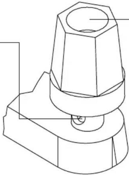
Banana Plugs
There are many types of banana plugs, some crimp, some solder. The Niles gold banana plug has 3 quick-connect binding post for the bare wire on the body of the plug. A banana plug is simply inserted into the jack at the end of the amplifier's binding post. Dual banana plugs will fit the binding post.
STEp DESCrlpTlon
| 1. Label all wires. | If you label the wires for their destination, rather than which terminal of the SI-1230 they are connected to, it will be easier to reconfigure your system in the future. |
| 2. Connect one stripped wire end or banana plug to the black terminal and one to the red terminal. CAUTION- Avoid having even a single strand of wire touching the chassis or another connector. | A. Split the speaker wire insulation so that at least two inches of each conductor are separated.B. Strip one half inch of insulation from the end of each conductor of the speaker wireC. Attach banana plugs or twist the strands of wire together and insert them into the appropriate binding post. |
INSTALLATION
BUSMATRIX™ INPUT SWITCH SETTING
Each channel has a dedicated BusMatrix™ DIP switch that assigns that channel's source. To assign a signal from the Main Bus Input, select one of the first three switches which will give you either Left (L), Right (R) or Mono (L+R). To assign the channel's dedicated input select the fourth switch. Only ONE switch should be selected to the "ON" position.
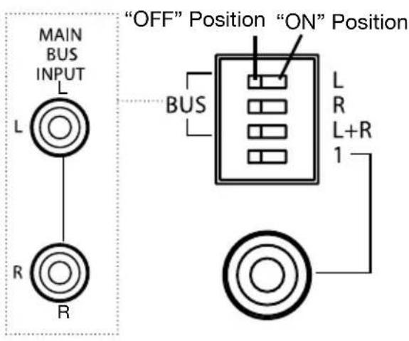
STEp DESCrlpTlon
| Move only ONE switch to the “ON” position for each channel. | ICaUTlon! The DIP switch physically allows you to move all four of the switches to the “On” position. If you accidentally set more than one switch “On”, you will create an undesirable mix of inputs on the entire bus. |
INSTALLATION
BRIDGING TWO CHANNELS INTO ONE
The SI-1230's bridging switches allow you to create a more powerful amplifier channel by combining or "bridging" two adjacent channels.
![graph TD A["LEVEL"] --> B["BRIDGED"] B --> C["USE CH 4 WHEN BRIDGED"] C --> D["ON MOBS"] D --> E["1 2 3 4 BUS L+R 3"] D --> F["ON MOBS"] F --> G["1 2 3 4 BUS L+R 4"] F --> H["ON MOBS"] H --> I["1 2 3 4 BUS L+R 4"]](/content/2026/05/948984/images/6cce761007b96273665cf77f5bbdc0d5827697c0a796219a2b27198fcdb2d8e2.jpg)
Slide the bridging switch in the direction of the arrow to bridge two adjacent amplifier channels. Set the controls of the newly bridged pair by using the EVEN numbered channel.
When two channels are bridged together, connect speakers to the two terminals labeled "Bridged".

STEp DESCrlpTlon
| 1. Choose which of the six pairs you wish to bridge and move the bridging switch for that pair to the “Bridged” position (toward arrow). | The 12 channels are grouped into 6 pairs (e.g. 1 & 2). Only the two channels within a pair can be bridged. Thus, only channels 1 and 2, or channels 3 and 4 could be bridged. You cannot bridge 2 and 3 for example. |
| CaUTlon! Do not connect a speaker load of less than eight ohms to a bridged channel. | A bridged channel on a SI-1230 is designed for an eight ohm minimum load. Connecting a speaker with a nominal impedance of less than 8 ohms may cause the SI-1230 to go into protection or be damaged. |
| 2. Connect the speaker wires to the two Bridged speaker terminals (BRIDGED +, BRIDGED -). Observe proper polarity markings. | Connect your speaker wire only to the red terminals of the two adjacent amplifier channels. If one of the speaker wires touches a black terminal (thereby grounding the red “hot” terminals) you will short circuit the amplifier. |
| CaUTlon! DO NOT connect a speaker selector or headphone junction box to the output of a bridged channel pair. | These connections to a bridged channel pair will result in either thermal shutdown or poor quality sound. |
| 3. Use the EVEN NUMBERED input, DIP switch, and level control for connections and configuration. | When two channels are bridged into one, make sure that the odd numbered input DIP switches are all in the “off” position. |
INSTALLATION
SETTING THE TURN-ON MODE SWITCH
The SI-1230 has three turn-on modes. Select the mode you want by sliding the mode switch. See Installation Considerations on page 14 for more information about each of the turn-on modes.
TIP: To conserve energy set the TURN ON mode to either AUDIO SENSE or TRIGGER INPUT. Use of the CONSTANT mode will prevent the amplifier from turning off when not in use wasting energy.

THE CONTROL OUTPUT
This terminal provides a 12V DC signal suitable for triggering Niles automated switchers, some motorized screens, some electric curtain controls, etc. This voltage is present only when the amplifier is active or on. When the amplifier turns off, the 12V signal is off.

| STEp DESCrlpTlon | |
| 1. Check the requirements of the device you want to control. | The control output has a maximum current capability of 150 mA. |
| 2. Connect the 3.5 mm Jack to the control output maintaining proper polarity (tip = +). | Niles makes an accessory cable plug FG00724. |
OPERATION
POWER SWITCH
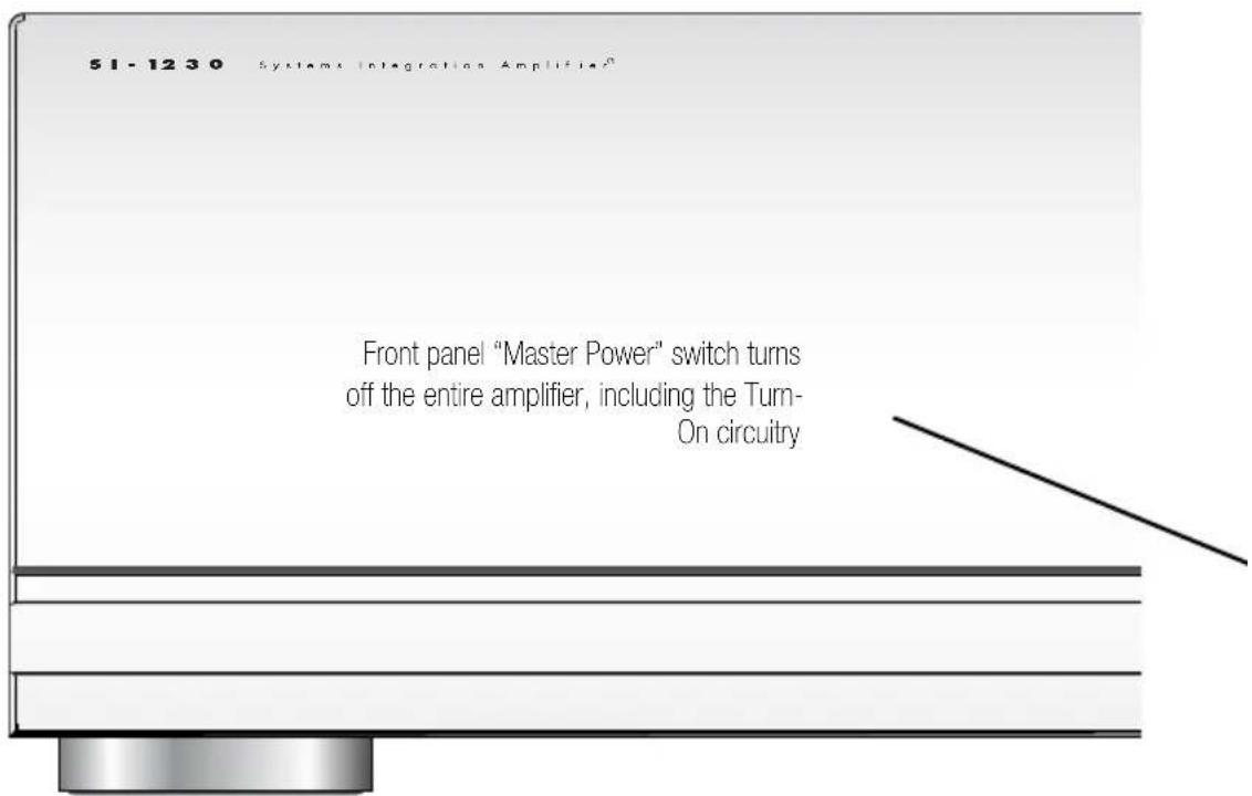
The front panel switch is a master or “vacation” power switch. No matter which turn-on mode you have selected, the master power switch will turn off all circuitry including the sensing circuitry. If you will not be using the amplifier for an extended period of time, turn the master power switch “Off” (push button switch out). When you would like to return to normal operation, turn the switch “On” (push button switch in).
Important Notes: Equipment is not completely disconnected from main power source when power switch is in the “OFF” position.
Power LED
The power LED indicates that the AC cord is plugged into a working AC power receptacle and that the power switch is in the “On” position.
Bicolor Status LED
The bicolor Status LED illuminates “green” when the amplifier circuitry has been turned on by the Turn-On circuits, and illuminates “red” to indicate activation of the amplifier’s built-in protection circuitry due to either a fault in the wiring or the speaker, or with the Niles System Integration Amplifier ® itself.
Using Level Controls as Limiters
If your system is remote controlled, or if you think that some of the users like to play the stereo too loudly, you can choose to calibrate the system so that it is limited to a volume level you assign. The SI-1230 allows you to set different volume levels for different rooms.
Calibrate your system volume levels with the steps outlined below:
- Lower all of the SI-1230 level controls to the minimum volume position. If there are any other amplifiers in the system, lower their level controls to the minimum (all of the amplifiers in your system must have level controls).
- Raise all of the individual in-wall volume controls to the loudest setting.
- Play a loud radio station with the tuner set to Mono.
- Raise the volume of your preamplifier or receiver slowly—if you hear any sound, lower the volume again and recheck all of your amplifier levels, they must be at minimum. If no sound is heard, proceed to step five.
- Have someone step into each room and listen as you adjust each level control to the desired maximum level for that room. Adjust the balance between speakers for the most common listening position in each room.
OPERATION
LISTENING AT HIGHER VOLUMES
Thirty watts is enough power to play a conventional speaker in a normal sized room loudly enough to completely drown out conversation. Even at levels like that, the SI-1230 will sound clear and clean. However, it requires more power to achieve a reasonable volume of sound in a large room than it does in a small room. It is possible (even if you are not a teenager) to turn the volume so high that the amplifier runs out of power. This creates “clipping” distortion.
Clipping distortion makes treble sound very harsh and unmusical. When you hear harsh sounding treble from any good speaker, turn the volume down immediately! Those harsh sounds are masking some much more powerful high frequency sound spikes which will quickly damage the tweeter of any loudspeaker.
If you continue to operate the amplifier at “clipping” power levels the protection circuits will operate when the amplifier overheats. The protection circuits reset when the amplifier’s internal circuitry cools. Reduce the volume to prevent a reoccurrence. Perpetually overdriving your speakers and amplifier is abuse and probably voids the manufacturer’s warranty of all affected products.
CLEANING AND MAINTENANCE
The internal parts of the SI-1230 are electronic and require no maintenance. Once a year it is appropriate to twist the RCA connectors on each input to remove any oxidation and improve conductivity.
You can clean only with dry cloth. Do not use any spray-type, abrasive cleaners on the amplifier.
TROUBLE-SHOOTING GUIDE
When there is a problem consult this guide first. If the problem persists, or you have additional questions, call your local Niles dealer or call Niles Technical Support at 1-800-289-4434. The most common problems relate to hook up. Have your configuration worksheet handy when you call.
| Symptom Possible Causes and Test Procedure | |
| No sound on one channel | BusMatrixTM DIP switch is not in the correct position. Check your configuration worksheet for the correct setting and verify.Short circuit or loose wire at speaker or amplifier terminals. Check that connections are secure and that there are no loose strands of wire crossing from the positive to the negative terminal at the back of the amplifier and the speaker.Short circuit or a break in the speaker wire. Disconnect the speaker wire at both ends, separate the 2 conductors at both ends and test with a meter for a short circuit. If there is no short, connect the two conductors at one end and test with a meter for continuity.Speaker is not working. Connect the speaker to a channel that plays another speaker. Audio cable to dedicated input is bad. Connect the non-working channel input to another cable that is known to be good.Bridging Switch is in the wrong position. Check your configuration worksheet for the correct setting and verify.The thermal protection circuit has operated because of overheating caused by over driving or inadequate ventilation. |
| No sound on some or all channels | BusMatrixTM DIP switches are not in the correct positions. Check your configuration worksheet and verify all settings.Audio cable to the main bus inputs is bad. Connect the non-working channel input to another cable that is known to be good. Some or all of the internal amplifier fuses are blown. (Return the amplifier to your dealer for service). |
| Hum from all the speakers | Hum may be caused by a ground loop between two components in the system. Test for a ground loop by reversing the AC plugs of any components in the system with non polarized AC plugs.Check for faulty cables, faulty source material, an ungrounded phono system, cable TV feed or a defective component. |
| Amp will not turn on | Master power switch must be on.AC power cord must be plugged into a working outlet.Test that the AC power receptacle is working. If the outlet tests O.K., the internal fuses are blown. Return the amplifier to your dealer for service. |
TROUBLE-SHOOTING GUIDE
| Symptom Possible Causes and Test Procedure | |
| Sound is distorted on one or all of the channels at normal volumes | BusMatrixTM DIP switches are not in the correct positions.Check your configuration worksheet and verify all settings. |
| Normal volume cannot be reached | One of the internal amplifier fuses is blown. (Return the amplifier to your dealer for service). |
| Bass sound is weak and the stereo image is “phasey” sounding in one room | Check that the bridging switch is “Off”. If two adjacent channels are connected normally but the bridging switch is set to the “Bridged” position, the two speakers will play out of phase with each other.The loudspeakers are wired out of phase. Reverse the connections at the back of one speaker. |
| A speaker connected to a bridged pair of amplifier channels sounds weak | Check that the bridging switch is “On”. |
BY PHONE (IN USA)
1-800-BUY-HIFI (289-4434)
BY PHONE (OUTSIDE USA)
1-760-710-0992
CUSTOMER SERVICE HOURS
8:00 AM to 5:30 PM PT
TECHNICAL SUPPORT HOURS
6:00 AM to 4:00 PM PT
ON THE WEB
www.nilesaudio.com
EMAIL TECHNICAL SUPPORT
techsupport@nilesaudio.com
EMAIL FOR PRODUCT SUGGESTIONS
productsuggestions@nilesaudio.com
SPECIFICATIONS
| Detail SI-1230 Series 2 | |
| Design Principle | Digital, high current bridgeable multi-channel amplifier |
| Continuous Average Power Output | 30 watts RMS per channel into 8 Ohms,40 watts RMS per channel into 4 Ohms (all channels driven) |
| Continuous Average Power Output Bridged | 80 watts RMS per channel into 8 Ohms |
| Frequency Response | 5Hz to 25kHz, +0dB/-3dB |
| Signal to Noise Ratio | 20Hz to 20kHz unweighted - >102dB |
| Total Harmonic Distortion | @ 1kHz <.05% |
| Channel Separation | @ 1kHz >70dB |
| Overall Dimensions | 17 1⁄4” (43.81 cm) wide5 3⁄4” (14.5 cm) high (including feet)16 1⁄4” (41.1 cm) deep |
| Weight | Weight 35lb., 15.8 kg |
| AC Mains: | 100-120 / 220-240 V~, 50 / 60 Hz, 500W |
For ease of use, the Configuration Worksheet can be enlarged on a photocopier.
BUS INS & OUTS CONNECTED TO
| Left Main Bus | |
| Right Main Bus | |
| Cascade Output |
CH#
BRIDGED
DIP
INPUT SOURCE SPEAKER
| 1 | ||||
| 2 | ||||
| 3 | ||||
| 4 | ||||
| 5 | ||||
| 6 | ||||
| 7 | ||||
| 8 | ||||
| 9 | ||||
| 10 | ||||
| 11 | ||||
| 12 |
MODE SETTINGS IN USE SPECIAL
| Constant | ||
| Audio Sense | ||
| Voltage Trigger | ||
| Control Output |
LIMITED WARRANTY
Niles Audio Corporation ("NILES") warrants to the original retail purchaser only that this product will be free of manufacturing defects in material and workmanship for the following periods and subject to the limitations and exclusions set forth below:
Lifetime Warranty
All Passive Amplifier Products (those not requiring AC or battery power).
Ten years from the date of purchase
All Other Passive Products (those not requiring AC or battery power).
Two years from the date of purchase
All Active Products (those requiring AC or battery power).
This warranty is not transferable to subsequent purchasers of the product. To obtain warranty service, contact the authorized dealer where you purchased your product or take the unit to the nearest authorized NILES dealer (with proof of purchase – claims made without proof of purchase will be denied) who will test the product and if necessary, forward it to NILES for service. If there are no authorized NILES dealers in your area, you must contact NILES to receive a factory Return Authorization Number. DO NOT RETURN ANY UNIT WITHOUT FIRST RECEIVING WRITTEN AUTHORIZATION AND SHIPPING INSTRUCTIONS FROM NILES.
Upon examination, NILES will, at its sole option and expense, repair or replace any product found to be defective. NILES will return the repaired or replaced unit to you via its usual shipping method from the factory to your address in the United States of America or Canada only. Any shipping costs for addresses outside of the United States or Canada shall be the responsibility of the purchaser. In the event that this model is no longer available and cannot be repaired effectively, NILES, at its sole option, may replace it with a different model of equal or greater value, or refund the original purchase price paid. THE FOREGOING ARE YOuR EXCLuSIVE REMEDIES FOR BREACH OF WARRANTY.
This Warranty does not include service or parts to repair damage caused by improper use or handling, including but not limited to damage caused by accident, mishandling, improper installation, commercial use, abuse, negligence, or normal wear and tear, or any defect caused by repair to the product by anyone other than NILES.
This warranty does not cover reimbursement for your costs of removing and transporting the product for warranty service evaluation, or installation of any replacement product provided under this warranty.
This Warranty will be void if:
- the Serial Number on the product has been removed, tampered with or defaced.
- the product was not purchased from an authorized dealer or reseller.
THE FOREGOING WARRANTIES ARE EXCLUSIVE AND IN LIEU OF ALL OTHER EXPRESSED AND IMPLIED WARRANTIES. NILES EXPRESSLY DISCLAIMS ALL SUCH OTHER WARRANTIES, INCLUDING BuT NOT LIMITED TO IMPLIED WARRANTIES OF MERCHANTABILITY, FITNESS FOR A PARTICuLAR PURPOSE AND NON-INFRINGEMENT, WITH RESPECT TO THE PRODUCT. TO THE MAXIMuM EXTENT PERMITTED BY LAW, NILES SHALL NOT BE RESPONSIBLE FOR ANY INCIDENTAL OR CONSEQUENTIAL DAMAGES EXCEPT TO THE EXTENT PROVIDED (OR PROHIBITED) BY APPLICABLE LAW, EVEN IF NILES HAS BEEN ADVISED OF THE POSSIBILITY OF SUCH DAMAGES.
Notwithstanding the above, if you qualify as a “consumer” under the Magnuson-Moss Warranty Act, or applicable state laws, then you may be entitled to any implied warranties allowed by law for the Warranty Period. Further, some states do not allow limitations on how long an implied warranty lasts or allow the exclusion or limitation of consequential damages, so such limitations may not apply to you. This warranty gives you specific legal rights, and you may also have other rights which vary from state to state.
For the name of your nearest authorized NILES dealer, contact: THE AVC GROUP, 1969 Kellogg Avenue, Carlsbad, CA 92008, or call (800) BUY-HIFI (289-4434) or (760) 710-0992. Please be advised that NILES only sells its products via the Internet through a select group of authorized Internet dealers. These are listed on our website at www.nilesaudio.com. Products offered on the Internet through unauthorized Internet dealers are not covered by the NILES warranty and may be either:
1) goods acquired on a secondary or grey market
2) counterfeit or stolen goods
3) damaged, or defective goods
Please fill in your product information and retain for your records.
Model
Serial No.
Purchase Date
ATTENTION: TO OuR VALuED CONSuMERS:
To insure that consumers obtain quality pre-sale and after-sale support and service, NILES products are sold exclusively through authorized dealers. This warranty is VOID if the products have been purchased from an unauthorized dealer.

NILES®
BLENDING HIGH FIDELITY AND ARCHITECTURE®
1690 Corporate Circle, Petaluma, CA 94954
1-760-710-0992
1-800-BUY-HIFI - www.nilesaudio.com
©2012 Core Brands, LLC. All rights reserved. Niles and the Niles logos are registered trademarks of Core Brands, LLC. All other trademarks are the property of their respective owners. We reserve the right to change specifications, descriptions and prices without notice. The technical and other information contained herein is not intended to set forth all technical and other specifications. Designed and engineered in the USA. 9901253 Rev D


- Congratulations
- Important safety instructions
- Warning: to reduce the risk of fire or electric shock, do not expose this apparatus to rain or moisture
- Fcc required text
- Introduction
- Bridgable power amplifiers
- Features and benefits
- Real world power
- Twelve to six channel configurable power
- Freedom from noise and cross-talk
- Transparent sound
- Busmatrix™ selector
- Features and benefits continued
- Independent level controls
- Turn-on modes
- Automatic protection
- Status display for troubleshooting
- Designed and engineered in the usa
- System design basics
- System design basics continued
- System design considerations
- Speaker compatibility
- Cable and wire
- System design considerations continued
- Using mono for smoother coverage
- Bridging channels for areasthat require more volume and power
- These are some of the most common dos and don'ts
- Applications
- Advantages of using the SI-1230 in a single zone system
- Using a dual-zone receiver for two listening zones
- Expanding a multizone system to include more rooms
- Adding preamps to create more listening zones
- Configuring your system
- Installation considerations
- Placement
- Front and rear panel details
- Installation
- Line level audio input
- Cascade audio outputs
- Ac power plug
- Speaker wire connections
- Bare wire
- Banana plugs
- Busmatrix™ input switch setting
- Bridging two channels into one
- Setting the turn-on mode switch
- The control output
- Operation
- Power switch
- Power led
- Bicolor status led
- Using level controls as limiters
- Calibrate your system volume levels with the steps outlined below
- Listening at higher volumes
- Cleaning and maintenance
- Trouble-shooting guide
- Specifications
- Limited warranty
- Attention: to our valued consumers
- Niles®
Brand : Niles
Model : SI-1230 Series 2
Category : Receiver