
FPBM307NTF - Microwave FRIGIDAIRE - Free user manual and instructions
Find the device manual for free FPBM307NTF FRIGIDAIRE in PDF.


| Product Type | Over-the-Range Microwave with Integrated Hood |
| Brand | Frigidaire |
| Model | FPBM307NTF |
| Power Supply | 120 V AC, 60 Hz, 15 A, 1.6 kW |
| Product Weight | 28.5 to 38.5 kg (63 to 85 lb) |
| Total Installed Weight (max) | 51.3 to 61.2 kg (113 to 135 lb) |
| Microwave Functions | Yes |
| Hood Function | Yes |
| Convection Function | Yes (with metal trivet included) |
| Venting Options | Outdoor venting (top, rear) or air recirculation |
| Grease Filters | 2 included (packed separately) |
| Charcoal Filter | Factory installed (some models) |
| Turntable | Yes (glass tray and ring) |
| Shelf | 1 included |
| Metal Trivet | 2 included |
| Vent Adapter | 1 included |
| Cutout Width | 30 in (76.2 cm) |
| Plug Type | Three-prong grounded plug |
| Safety | Grounding required; shut off breaker before installation |
| Installation | Requires attachment to at least one wall stud and upper cabinet; two people recommended |
Frequently Asked Questions - FPBM307NTF FRIGIDAIRE
User questions about FPBM307NTF FRIGIDAIRE
0 question about this device. Answer the ones you know or ask your own.
Ask a new question about this device
Download the instructions for your Microwave in PDF format for free! Find your manual FPBM307NTF - FRIGIDAIRE and take your electronic device back in hand. On this page are published all the documents necessary for the use of your device. FPBM307NTF by FRIGIDAIRE.
USER MANUAL FPBM307NTF FRIGIDAIRE
Installation Over the Range Instructions Microwave Oven
Questions? Call 1-877-435-3287(US) or 1-800-265-8352(Canada)
BEFORE YOU BEGIN
Read these instructions completely and carefully.
- IMPORTANT — Save these instructions for local inspector's use.
- IMPORTANT — Observe all governing codes and ordinances.
-
Note to Installer – Be sure to leave these instructions with the Consumer.
-
Note to Consumer – Keep these instructions for future reference.
- Skill level – Installation of this appliance requires basic mechanical and electrical skills.
- Proper installation is the responsibility of the installer.
- Product failure due to improper installation is not covered under the Warranty.
natural_image
Line drawing of a cabinet or oven with a door and handle (no text or symbols)READ CAREFULLY.
KEEP THESE INSTRUCTIONS.
CONTENTS
General information
Important Safety Instructions .... 3
Electrical Requirements .... 3
Damage – Shipment/ Installation.... 4
Parts Included.... 4
Tools You Will Need 5
Mounting Space 5
Step-by-step installation guide
Placement of The Mounting Plate 6-8
Removing the Mounting Plate 6
Finding the Wall Studs...... 6
Determining Wall Plate Location....7
Aligning the Wall Plate 8
Installation Types.... 9-22
Hood Exhaust 10-11
A Outside Top Exhaust 12–15
Attach Mounting Plate to Wall......12
Preparation of Top Cabinet......13
Adapting Microwave Blower for
Outside top Exhaust 13–14....
Checking for Proper Damper
Operation....14
Mount the Microwave Oven .....14-15
Adjust the Exhaust Adaptor ....15
Connecting Ductwork....15
B Outside Back Exhaust.... 16–19
Preparing Rear Wall for
Outside Back Exhaust....16
Remove Blower Plate 16.....
Attach Mounting Plate to Wall .....17
Preparation of Top Cabinet ......17
Adapting Microwave Blower
for Outside Back Exhaust....17–18
Mount the Microwave Oven ....19
C Recirculating 20–22
Attach Mounting Plate to Wall ......20
Preparation of Top Cabinet ......21
Check Blower Plate 21
Mount the Microwave Oven .....21–22
Installing or Change the
Charcoal Filter 22
Before You Use Your Microwave 23
Template Information.... 24
IMPORTANT SAFETY INSTRUCTIONS
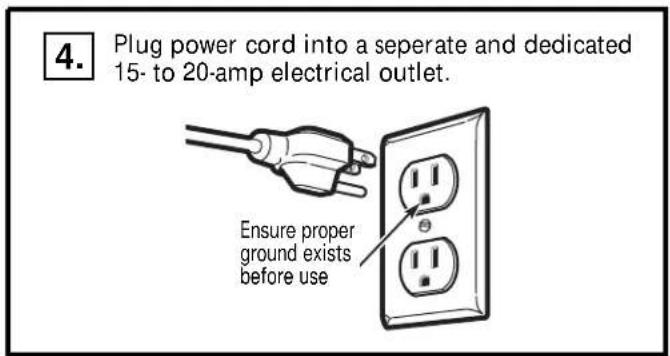
This product requires a three-prong grounded outlet. The installer must perform a ground continuity check on the power outlet box before beginning the installation to ensure that the outlet box is properly grounded. If not properly grounded, or if the outlet box does not meet electrical requirements noted (under ELECTRICAL REQUIREMENTS), a qualified electrician should be employed to correct any deficiencies.

natural_image
Illustration of a hand interacting with an electrical outlet panel (no text or symbols visible)CAUTION: For personal safety, remove house fuse or open circuit breaker before beginning installation to avoid severe or fatal shock injury.
CAUTION: For personal safety, the mounting surface must be capable of supporting the cabinet load, in addition to the added weight of this 63–85 pound (28.5–38.5 kg) product, plus additional oven loads of up to 50 pounds (22.7 kg) or a total weight of 113–135 pounds (51.3–61.2 kg).
CAUTION: For personal safety, this product cannot be installed in cabinet arrangements such as an island or a peninsula. It must be mounted to BOTH a top cabinet AND a wall.
NOTE: For easier installation and personal safety, it is recommended that two people install this product.
IMPORTANT – PLEASE READ CAREFULLY. FOR PERSONAL SAFETY, THIS APPLIANCE MUST BE PROPERLY GROUNDED TO AVOID SEVERE OR FATAL SHOCK.

The power cord of this appliance is equipped with a three-prong (grounding) plug which mates with a standard three-prong (grounding) wall receptacle to minimize the possibility of electric shock hazard from this appliance.
You should have the wall receptacle and circuit checked by a qualified electrician to make sure the receptacle is properly grounded.
Where a standard two-prong wall receptacle is encountered, it is very important to have it replaced with a properly grounded three-prong wall receptacle, installed by a qualified electrician.
DO NOT, UNDER ANY CIRCUMSTANCES, CUT, DEFORM OR REMOVE ANY OF THE PRONGS FROM THE POWER CORD. DO NOT USE WITH AN EXTENSION CORD.
ELECTRICAL REQUIREMENTS
Product rating is 120 volts AC, 60 Hertz, 15 amps and 1.6 kilowatts. This product must be connected to a separate and dedicated supply circuit of the proper voltage and frequency. Wire size must conform to the requirements of the National Electrical Code or the prevailing local code for this kilowatt rating. The power supply cord and plug should be brought to a separate and dedicated 15- to 20- ampere branch circuit single grounded outlet. The outlet box should be located in the cabinet above the microwave oven. The outlier box and supply circuit should be installed by a qualified electrician and conform to the National Electrical Code or the prevailing local code.
DAMAGE—SHIPMENT/ INSTALLATION
- If the unit is damaged in shipment, return the unit to the store in which it was bought for repair or replacement.
- If the unit is damaged by the customer, repair or replacement is the responsibility of the customer.
- If the unit is damaged by the installer (if other than the customer), repair or replacement must be made by arrangement between customer and installer.
PARTS INCLUDED
HARDWARE PACKET
| PART QUANTITY | ||
 | Wood Screws 2 (1/4" × 2") | |
 | Toggle Bolts (and wing nuts) (3/16" × 3") | 2 |
 | Self-Aligning Machine 3 Screws (1/4"-28 × 3^1/4") | |
 | Nylon Grommet(for metal cabinets) | 1 |
You will find the installation hardware contained in a packet with the unit. Check to make sure you have all these parts.
NOTE: Some extra parts are included.
PARTS INCLUDED (CONT.)
ADDITIONAL PARTS
| PART | QUANTITY | |
 | CabinetTop Template | 1 |
 | Rear Wall Template | 1 |
 | Installation Instructions | 1 |
| Use & Care Manual | 1 | |
For some models 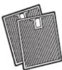 | Grease Filters | 2 |
 | Exhaust adaptor | 1 |
 | Glass Tray | 1 |
 | Tru ntable Ring | 1 |
For some models  | Convection wire rack | 2 |
 | Shelf | 1 |
TOOLS YOU WILL NEED

1 Phillips screwdriver

Pencil
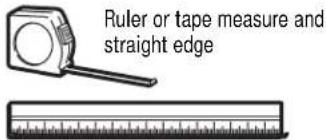


Tin snips (for cutting damper, if required)
Scissors
(to cut template, if necessary)

Electric drill with 316 ", 12 " and 58 " drill bits

Filler blocks or scrap wood pieces, if needed for top cabinet spacing (used on recessed bottom cabinet installations only)

Gloves

natural_image
Three technical line drawings of electrical components: a motor, a plug, and a hook (no text or symbols)Saw (saber, hole or keyhole)

Stud finder
Hammer (optional)

Safety goggles

Level

Duct and masking tape
MOUNTING SPACE

NOTES:
- Thespacebetweenthecabinetsmustbe 30"(76.2cm) wideandfreeofobstructions.
- If you are going to every your microwave oven to the outside, see Hood Exhaust Section for exhaust duct preparation.
- When installing them microwave oven beneath smooth, flat cabinets, be careful to allow the instructions on the top cabinet template or power cord clearance.
- Asaguidetoinstallation,seepage24forMounting TemplateInformation.
- If the cabinet depth including the cabinet doors is more than 13' then the unit must be spaced out from wall using adequate materials supporting 150 lbs to allow proper top vent air exhaust/ intake.

natural_image
Simple line drawing of a door with a handle and curved lid, no text or symbols present
1 PLACEMENT OF THE MOUNTING PLATE
A. REMOVINGTHEMICROWAVE OVENFROM THECARTON/REMOVINGTHEMOUNTING PLATE
1 Remove the installation instructions, use and care, exhaust adapter, turntable ring, shelf, glass tray and the small hardware bag. Do not remove the Styrofoam protecting the front of the oven.
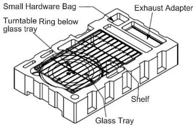
2 Foldbackall4cartonflapsfullyagainstcarton sides. Thencarefullyrolltheovenandcartonover ontothetopside. Theovenshouldberesting in theStyrofoam.

3 Pullthecartonupandofftheoven.
4 Cutthemiddleoftheouterprotectiveplasticbagto remove the mountinglate
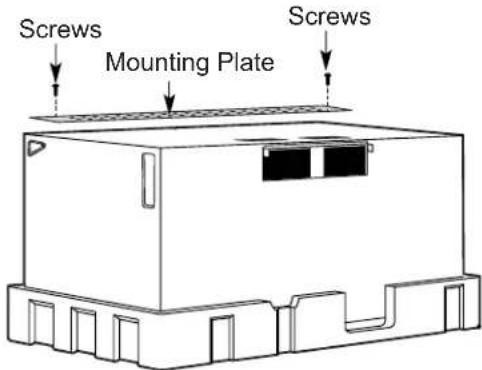
5 Remove the screws from each end of the mounting plate. This plate will be used as the rear wall template and for mounting. Reinstall the screws into the holes where they were removed.
B. FINDINGTHEWALLSTUDS

1 Findthestuds, using one of the following methods:
A. Studfinder—amagnetic device which locatesnails.
B. Useahammertotaplightlyacrossthe mountingsurfacetofindasolidsound. Thiswillindicateastudlocation.
2 Afterlocatingthestud(s), findthecenter by probingthewallwithasmallnailtofindtheedges ofthestud. Thenplaceamarkhalfwaybetween theedges. Thecenterofanyadjacentstudsshould be16" (40.6cm) or 24" (61cm) fromthismark.
3 Drawalinedownthecenterofthestuds. THEMICROWAVEMUSTBECONNECTEDTO ATLEASTONEWALLSTUD.
C. DETERMINING WALL PLATE LOCATION UNDER YOUR CABINET
Plate position-beneath flat bottom cabinet

Draw a vertical line on the wall at the center of the 30" wide space. Tape the Rear Wall Template onto the wall matching the centerline and touching the bottom of the cabinet.
Plate position-beneath framed recessed cabinet bottom
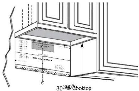
Draw a vertical line on the wall at the center of the 30" space.
Tape the Rear Wall Template onto the wall matching the centerline and touching the bottom cabinet frame.
Plate position-beneath recessed bottom cabinet with front overhang

Your cabinets may have decorative trim that interferes with the microwave installation. Remove the decorative trim to install the microwave properly and to make it level.
Use a level to make sure the cabinet bottom is level. If the cabinets have a front overhang only, with no back or side frame, install the mounting plate down the same distance as the front overhang depth. This will keep the microwave level.
1 Measure the inside depth of the front overhang.
2 Draw a horizontal line on the back wall an equal distance below the cabinet bottom as the inside depth of the front overhang.
3 For this type of installation with front overhang only, align the mounting tabs with this horizontal line, not touching the cabinet bottom as described in Step D.
D. ALIGNING THE WALL PLATE
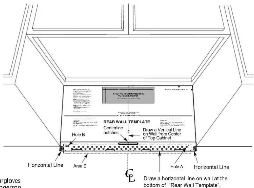
CAUTION: Weargloves to avoid cutting fingerson sharpedges.
1 Draw a vertical line on the wall at the center of the 30" wide space.
2 Draw a horizontal line on the wall at the bottom of "Rear Wall Template".
3 Find a wall stud in area "E" of mounting plate Refer to section 1B. Finding the wall studs.
4 For attaching the mounting plate into stud drill a 3/16" hole into wood stud. Drill a 5/8" hole for toggle bolt in 1 other location (Hole A or Hole B) NOTE: DO NOT MOUNT THE PLATE AT THIS TIME.
NOTE: Holes A and B are inside area E. If neither of Holes A and B are not in a stud, find a stud somewhere in area E and draw a circle to line up with the stud. It is important to have at least one wood screw mounted firmly in a stud to support the weight of the microwave. Set the mounting plate aside.
2 | INSTALLATION TYPES (Choose A, B or C)
This microwaveoven is designed for adaptation to the following three types of ventilation:
A. Outside Top Exhaust (Vertical Duct)
B.OutsideBackExhaust(HorizontalDuct)
C. Recirculating(Non-VentedDuctless)
NOTE: This microwave is shipped assembled for Recirculating. Select the typeof ventilation required for your installation and proceed to that section.
A OUTSIDE TOP EXHAUST (VERTICAL DUCT)

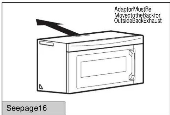
B OUTSIDE BACK EXHAUST (HORIZONTAL DUCT)
C RECIRCULATING (NON-VENTED DUCTLESS)

natural_image
Line drawing of a microwave oven with a black arrow indicating airflow or heat transfer (no text or symbols on the device itself)Modelsareshippedfor recirculatingexhaust. Somemodelshavea disposablecharcoalfilter installedtohelpremove smokeandodors.
NOTE: Read the next two pages only if you plan to vent your exhaust to the outside. If you plan to recirculate the air back into the room, proceed to page 20.
INSTALLATION INSTRUCTIONS FOR EXTERNAL EXHAUST DUCTING
NOTE: If you need to install ducts, note that the total duct length of 314 " x 10" (8.2 x 25.4 cm) rectangular or 5" (12.7 cm) diameter/6" (15.2 cm) diameter round duct should not exceed 120 equivalent feet (36.5 m).
Outside ventilation requires an EXTERNAL EXHAUST DUCT. Read the following carefully.
NOTE: It is important that venting be installed using the most direct route and with as few elbows as possible. This ensures clear venting of exhaust and helps prevent blockages. Also, make sure dampers swing freely and nothing is blocking the ducts.
Exhaust connection:
The exhaust adaptor has been designed to mate with a standard 3¼" x 10" (8.2 x 25.4 cm) rectangular duct. If a round duct is required, a rectangular-to-round transition adaptor must be used. A 5" (12.7cm)/ 6" (15.2cm) diameter duct is acceptable to use.
Maximum duct length:
For satisfactory air movement, the total duct length of 3^1/4 x 10" (8.2 x 25.4 cm) rectangular or 5" (12.7 cm) diameter/6" (15.2 cm) diameter round duct should not exceed 120 equivalent feet (36.5 m).
Elbows, transitions, wall and roof caps, etc., present additional resistance to airflow and are equivalent to a section of straight duct which is longer than their actual physical size. When calculating the total duct length, add the equivalent lengths of all transitions and adaptors plus the length of all straight duct sections. The chart below shows you how to calculate total equivalent ductwork length using the approximate feet of equivalent length of some typical ducts.
| DUCT PIECES LENGTH x USED = LENGTH | EQUIVALENT NUMBER EQUIVALENT | |
 | Rectangular-to-Round 5 Ft. (1.5 m) x ( ) = Ft. or mTransition Adaptor* | |
 | Wall Cap 40 Ft. (12.2 m) x ( ) = Ft. or m | |
 | 90° Elbow 10 Ft. (3 m) x ( ) = Ft. or m | |
 | 45° Elbow 5 Ft. (1.5 m) x ( ) = Ft. or m | |
 | 90° Elbow 25 Ft. (7.6 m) x ( ) = Ft. or m | |
 | 45° Elbow 5 Ft. (1.5 m) x ( ) = Ft. or m | |
 | Roof Cap | 24 Ft. (7.3 m) x ( ) = Ft. or m |
| [PHXT] | Straight Duct 6" (15.2 cm)Round or 31⁄4" x 10"(8.2 x 25.4 cm Rectangular) | 1 Ft. (0.3 m) x ( ) = Ft. or m |
| Total Ductwork = | Ft. or m | |

* IMPORTANT: If a rectangular-to-round transition adaptor is used, the bottom corners of the damper will have to be cut to fit, using the tin snips, in order to allow free movement of the damper.
Equivalent lengths of duct pieces are based on actual tests and reflect requirements for good venting performance with any vent hood.
EXTERNAL EXHAUST DUCTING
OUTSIDE TOP EXHAUST (EXAMPLE ONLY)
The following chart describes an example of one possible ductwork installation.

natural_image
Simple line drawing of a cylindrical object with a flanged top and tapered base (no text or symbols)| DUCT PIECES LENGTH x USED = LENGTH | EQUIVALENT NUMBER EQUIVALENT | |
 | Roof Cap 24 Ft. (7.3 m) x (1) = 24 Ft. (7.3 m) | |
 | 12 Ft. (3.6 m) Straight Duct (6"/15.2 cm Round) | 12 Ft. (3.6 m) x (1) = 12 Ft. (3.6 m) |
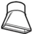 | Rectangular-to-Round 5 Ft. ( Transition Adaptor* | 1.5 m) x (1) = 5 Ft. (1.5 m) |
| Equivalent lengths of duct pieces are based on actual tests and reflect requirements for good venting performance with any vent hood.Total Length = | 41 Ft. (12.5 m) | |
* IMPORTANT: If a rectangular-to-round transition adaptor is used, the bottom corners of the damper will have to be cut to fit, using the tin snips, in order to allow free movement of the damper.
OUTSIDE BACK EXHAUST (EXAMPLE ONLY)
The following chart describes an example of one possible ductwork installation.
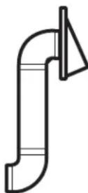 | DUCT PIECES | EQUIVALENT LENGTH* NUMBER x USED = LENGTH | EQUIVALENT | |
| Wall Cap | 40 Ft. (12.2 m) x (1) = 40 Ft. (12.2 m) | |||
| 3 Ft. Straight Duct (31⁄4" x 10"/8.2 x 25.4 cm Rectangular) | 3 Ft. (0.9 m) x (1) = 3 Ft. (0.9 m) | |||
| 90° Elbow | 10 Ft. (3 m) x (2) = 20 Ft. (3 m) | |||
| Equivalent lengths of duct pieces are based on actual tests and reflect requirements for good venting performance with any vent hood. Total Length = | 63 Ft. (19.2 m) | |||
| DUCT PIECES | EQUIVALENT LENGTH* NUMBER x USED = LENGTH | EQUIVALENT | |
| Wall Cap | 40 Ft. (12.2 m) x (1) = 40 Ft. (12.2 m) | ||
| 3 Ft. Straight Duct (31⁄4" x 10"/8.2 x 25.4 cm Rectangular) | 3 Ft. (0.9 m) x (1) = 3 Ft. (0.9 m) | ||
| 90° Elbow | 10 Ft. (3 m) x (2) = 20 Ft. (3 m) | ||
| Equivalent lengths of duct pieces are based on actual tests and reflect requirements for good venting performance with any vent hood. Total Length = | 63 Ft. (19.2 m) | ||
NOTE: For back exhaust, care should be taken to align exhaust with space between studs, or wall should be prepared at the time it is constructed by leaving enough space between the wall studs to accommodate exhaust.
A | OUTSIDE TOP EXHAUST (Vertical Duct)
INSTALLATION OVERVIEW
A1. Attach Mounting Plate to Wall
A2. Prepare Top Cabinet
A3. Adapting Microwave Blower for Outside Top Exhaust
A4. Check Damper Operation
A5. Mount Microwave Oven
A6. Adjust Exhaust Adaptor
A7. Connect Ductwork
IMPORTANT NOTES:
- Make sure the screws for the blower motor and blower plate are securely tightened when they are reinstalled. This will help to prevent excessive vibration.
• Make sure the motor wiring has been properly routed and secured, and that the wires are not pinched.
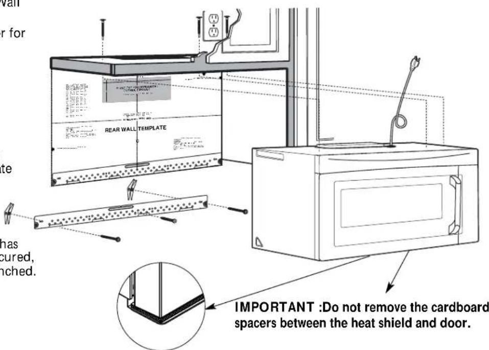
A1. ATTACH THE MOUNTING PLATE TO THE WALL

natural_image
Technical line drawing of a structural joint or panel assembly (no text or symbols present)Attach the plate to the wall using toggle bolts. At least one wood screw must be used to attach the plate to a wall stud.
1 Remove the toggle wings from the bolts.
2 Insert the bolts into the mounting plate through the holes designated to go into drywall and reattach the toggle wings to 34 " (19 mm) onto each bolt.
To use toggle bolts:

3 Place the mounting plate against the wall and insert the toggle wings into the holes in the wall to mount the plate.
NOTE: Before tightening toggle bolts and wood screw, make sure the bottom of the mounting plate touch the bottom of the cabinet when pushed flush against the wall and that the plate is properly centered under the cabinet.
CAUTION: Be careful to avoid pinching fingers between the back of the mounting plate and the wall.
4 Tighten all bolts. Pull the plate away from the wall to help tighten the bolts.
A2. USE TOP CABINET TEMPLATE FOR PREPARATION OF TOP CABINET
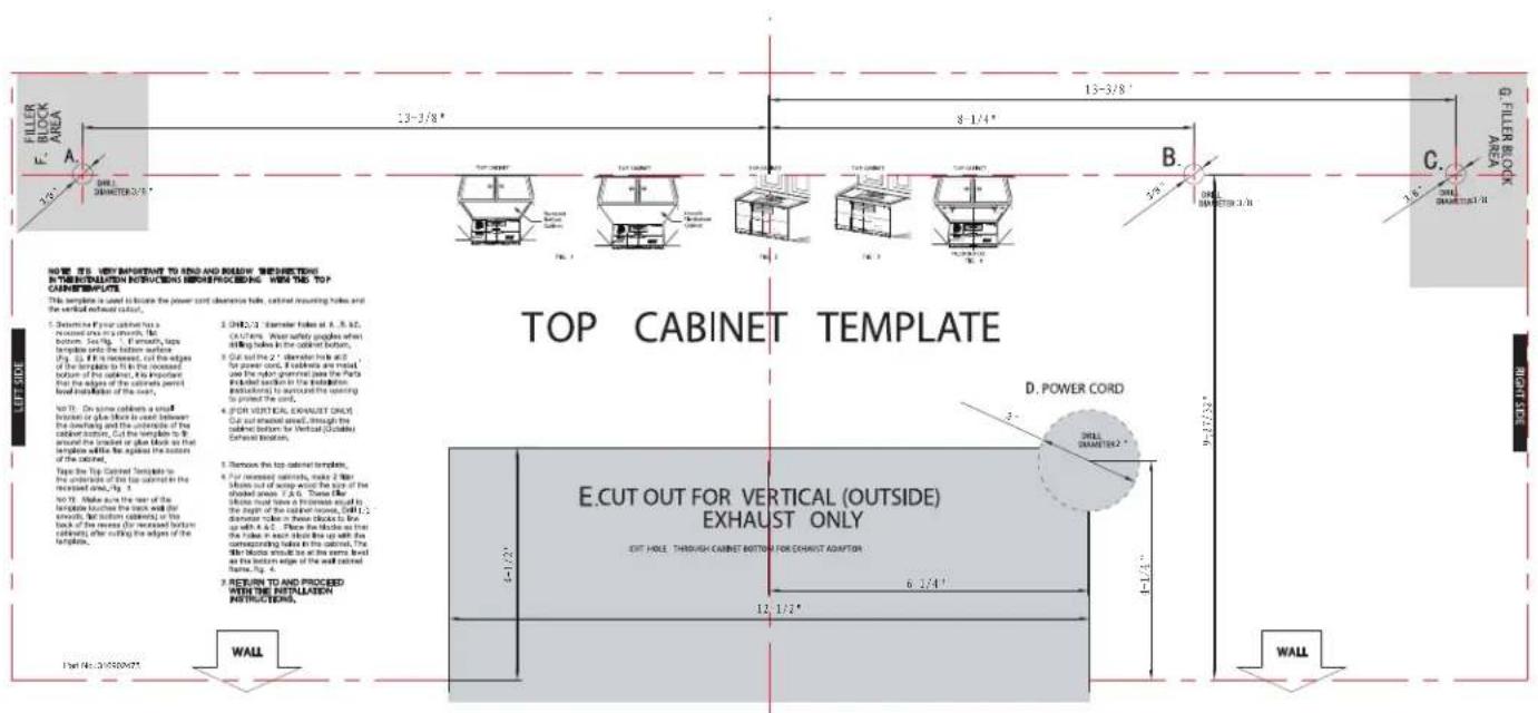
You need to drill holes for the top support screws, a hole large enough for the power cord to fit through, and a cutout large enough for the exhaust adaptor.

natural_image
Line drawing of a hand using a tool to clean or install a wall-mounted device (no text or symbols visible)- Read the instructions on the TOP CABINET TEMPLATE.
- Tape it underneath the top cabinet.
- Drill the holes, following the instructions on the TOP CABINET TEMPLATE.
CAUTION: Wear safety goggles when drilling holes in the cabinet bottom.
2 Carefully pull out the blower unit. The wires will extend far enough to allow you to adjust the blower unit.

3 Roll the blower unit 90° so that fan blade openings are facing out the top of the microwave.
Before Rotation After Rotation


natural_image
Technical diagram of a mechanical assembly with labeled components (no readable text or symbols)A3. ADAPTING MICROWAVE BLOWER FOR OUTSIDE TOP EXHAUST
1 Place the microwave in its upright position, with the top of the unit facing up.

Remove the screw that holds the blower plate to the microwave. Remove and save the screw holding the blower motor to the microwave.
4 Place the blower unit back into the opening.
AFTER: Fan Blade Openings Facing Top
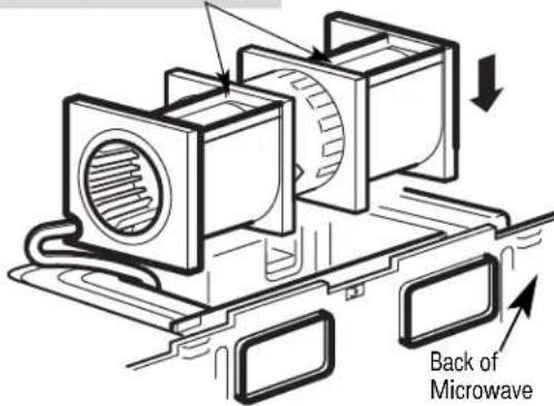
CAUTION: Do not pull or stretch the blower unit wiring. Make sure the wires are not pinched, and that they are properly secured.
A3. ADAPTING MICROWAVE BLOWER FOR OUTSIDE TOP EXHAUST
5 Secure blower unit to microwave with the screw removed in Step 1. Make sure the screw is tight.
6 Replace blower plate with the screw removed in Step 1. Make sure the screw is tight.

7 Attach the exhaust adaptor to the top of the blower plate by sliding it into the guides of the blower plate.

Push in securely until it is in the locking tabs. Take care to assure that the damper hinge is installed so that the damper swings freely.
- Make sure tape securing damper is removed and damper pivots easily before mounting microwave.
- You will need to make adjustments to assure proper alignment with your house exhaust duct after the microwave is installed.
natural_image
Three-panel line drawing showing a person crossed out of a box, another with a cross symbol, and a third holding a box (no text or symbols present)FOR EASIER INSTALLATION AND PERSONAL SAFETY, WE RECOMMEND THAT TWO PEOPLE INSTALL THIS MICROWAVE OVEN.
IMPORTANT: Do not grip or use the handle or heat shield during installation. Do not remove the cardboard spacers between the heat shield and door.
NOTE: If your cabinet is metal, use the nylon grommet around the power cord hole to prevent cutting of the cord.
NOTE: We recommend using filler blocks if the cabinet front hangs below the cabinet bottom shelf.
IMPORTANT: If filler blocks are not used, case damage may occur from overtightening screws.
NOTE: When mounting the microwave oven, thread power cord through hole in bottom of top cabinet. Keep it tight throughout Steps 1–3. Do not pinch cord or lift oven by pulling cord.

3 Insert a self-aligning screw through top center cabinet hole. Temporarily secure the oven by turning the screw at least two full turns after the threads have engaged. (It will be completely tightened later.) Be sure to keep power cord tight. Be careful not to pinch the cord, especially when mounting flush to bottom of cabinet.
4 Attach the microwave oven to the top cabinet.
5 Insert 2 self-aligning screws through outer top cabinet holes. Turn two full turns o each screw.

7 Tighten the outer two screws to the top of the microwave oven. (While tightening screws, hold the microwave oven in place against the wall and the top cabinet.)

natural_image
Hand inserting a small rectangular object into a grid-patterned panel (no text or symbols visible)8 Install grease filters. See the Owner's Manual packed with the microwave.
A6. ADJUST THE EXHAUST ADAPTOR
Open the top cabinet and adjust the exhaust adaptor to connect to the house duct.
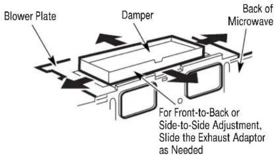
A7. CONNECTING DUCTWORK

1 Extend the house duct down to connect to the exhaust adaptor.
2 Seal exhaust duct joints using foldable tape for high temperature applications.
IMPORTANT: Remove the cardhoard spacers between heat shield and door.
B | OUTSIDE BACK EXHAUST (Horizontal Duct)
INSTALLATION OVERVIEW
B1. Prepare Rear Wall
B2. Remove Blower Plate
B3. Attach Mounting Plate to Wall
B4. Prepare Top Cabinet
B5. Adjust Blower
B6. Mount the Microwave Oven
IMPORTANT NOTES:
- Make sure the screws for the blower motor and blower plate are securely tightened when they are reinstalled. This will help to prevent excessive vibration.
• Make sure the motor wiring has been properly routed and secured, and that the wires are not pinched.
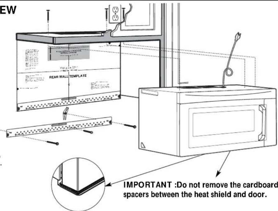
IMPORTANT : Do not remove the cardboard spacers between the heat shield and door.
B1. PREPARING THE REAR WALL FOR OUTSIDE BACK EXHAUST
You need to cut an opening in the rear wall for outside exhaust.

- Read the instructions on the REAR WALL TEMPLATE.
- Tape it to the rear wall.
- Cut the opening, following the instructions of the REAR WALL TEMPLATE.
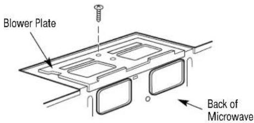
B2. REMOVE BLOWER PLATE
Remove and save the screw that holds the blower plate to the microwave. Lift off the blower plate.
B3. ATTACH THE MOUNTING PLATE TO THE WALL

natural_image
Architectural cross-section diagram of a building facade with structural elements and lighting fixtures (no text or labels)Attach the plate to the wall using toggle bolts. At least one wood screw must be used to attach the plate to a wall stud.
1 Remove the toggle wings from the bolts.
2 Insert the bolts into the mounting plate through the holes designated to go into drywall and reattach the toggle wings to 34 " (19 mm) onto each bolt.
To use toggle bolts:

3 Place the mounting plate against the wall and insert the toggle wings into the holes in the wall to mount the plate.
NOTE: Before tightening toggle bolts and wood screw, make sure the bottom of the mounting plate touch the bottom of the cabinet when pushed flush against the wall and that the plate is properly centered under the cabinet.
CAUTION: Be careful to avoid pinching fingers between the back of the mounting plate and the wall.
4 Tighten all bolts. Pull the plate away from the wall to help tighten the bolts.
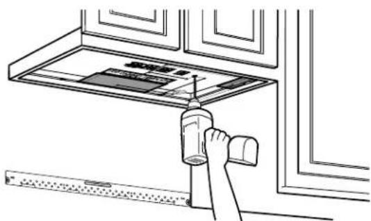
B4. USE TOP CABINET TEMPLATE FOR PREPARATION OF TOP CABINET
You need to drill holes for the top support screws and a hole large enough for the power cord to fit through.
natural_image
Line drawing of a hand using a tool to press or install a device on a wall, with no visible text or symbols.- Read the instructions on the TOP CABINET TEMPLATE.
- Tape it underneath the top cabinet.
- Drill the holes, following the instructions on the TOP CABINET TEMPLATE.
CAUTION: Wear safety goggles when drilling holes in the cabinet bottom.
B5. ADAPTING MICROWAVE BLOWER FOR OUTSIDE BACK EXHAUST
1 Remove and save screw that holds blower motor to microwave.
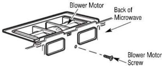
2 Carefully pull out the blower unit. The wires will extend far enough to allow you to adjust the blower unit.

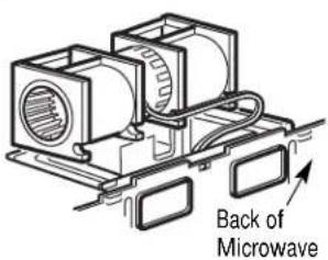
5 Gently remove the wires from the grooves. Reroute the wires through grooves on other side of the blower unit.
Before Rerouting After Rerouting

natural_image
Technical line drawing of two rectangular electronic components with internal circuitry (no text or symbols)
natural_image
Technical line drawing of two connected electrical enclosures (no text or symbols on the devices themselves)Wires Routed Through Right Side
6 Roll the blower unit 90° so that fan blade openings are facing out the back of the microwave.
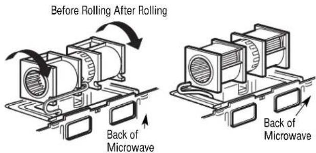
7 Place the blower unit back into the opening.
AFTER: Fan Blade Openings Facing Back

CAUTION: Do not pull or stretch the blower unit wiring. Make sure the wires are not pinched, and that they are properly secured.
NOTE: The blower unit exhaust openings should match exhaust openings on rear of microwave oven.
8 Secure the blower unit to the microwave with the original screw.

9 Replace the blower plate in the same position as before with the screw. Make sure the screw is tight.
10 Attach the exhaust adaptor to the rear of the oven by sliding it into the guides at the top center of the back of the oven.

Push in securely until it is in the lower locking tabs. Take care to assure that the damper hinge is installed so that it is at the top and that the damper swings freely.
B6. MOUNT THE MICROWAVE OVEN

natural_image
Illustration showing three scenes of people in a meeting or presentation setting, with no visible text or symbols.FOR EASIER INSTALLATION AND PERSONAL SAFETY, WE RECOMMEND THAT TWO PEOPLE INSTALL THIS MICROWAVE OVEN.
IMPORTANT: Do not grip or use the handle or heat shield during installation. Do not remove the cardboard spacers between the heat shield and door.
NOTE: If your cabinet is metal, use the nylon grommet around the power cord hole to prevent cutting of the cord.
NOTE: We recommend using filler blocks if the cabinet front hangs below the cabinet bottom shelf.
IMPORTANT: If filler blocks are not used, case damage may occur from overtightening screws.
NOTE: When mounting the microwave oven, thread power cord through hole in bottom of top cabinet. Keep it tight throughout Steps
1–3. Do not pinch cord or lift oven by pulling cord.
1 Lift microwave, tilt it forward, and hook slots at back bottom edge onto four lower tabs of mounting plate.
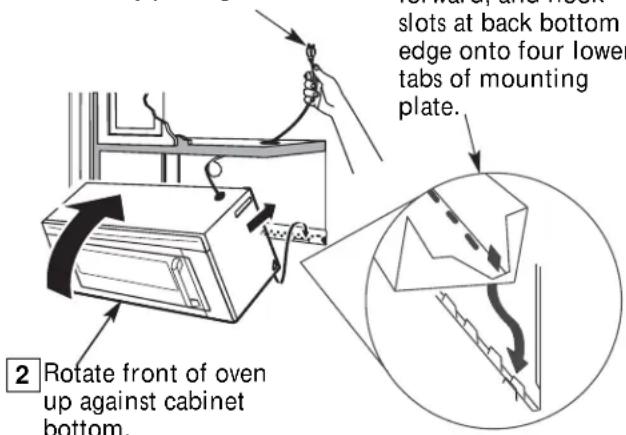
3 Insert a self-aligning screw through top center cabinet hole. Temporarily secure the oven by turning the screw at least two full turns after the threads have engaged. (It will be completely tightened later.) Be sure to keep power cord tight. Be careful not to pinch the cord, especially when mounting flush to bottom of cabinet.

4 Attach the microwave oven to the top cabinet.
5 Insert 2 self-aligning screws through outer top cabinet holes. Turn two full turns on each screw.

7 Tighten the outer two screws to the top of the microwave oven. (While tightening screws, hold the microwave oven in place against the wall and the top cabinet.)
natural_image
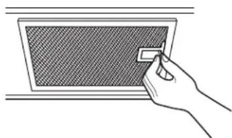
Hand holding a small object over a textured rectangular panel (no text or symbols visible)8 Install grease filters. See the Owner's Manual packed with the microwave.
IMPORTANT: Remove the cardhoard spacers between heat shield and door.
C | RECIRCULATING (Non-Vented Ductless)
INSTALLATION OVERVIEW
C1. Attach Mounting Plate to Wall
C2. Prepare Top Cabinet
C3. Check Blower Plate
C4. Mount the Microwave Oven
C5. Install or change Charcoal Filter
IMPORTANT NOTES:
- Make sure the screws for the blower motor and blower plate are securely tightened when they are reinstalled. This will help to prevent excessive vibration.
• Make sure the motor wiring has been properly routed and secured, and that the wires are not pinched.

IMPORTANT : Do not remove the cardboard spacers between the heat shield and door.
C1. ATTACH THE MOUNTING PLATE TO THE WALL

natural_image
Architectural cross-section diagram of a building facade with structural elements and lighting fixtures (no text or labels)Attach the plate to the wall using toggle bolts. At least one wood screw must be used to attach the plate to a wall stud.
NOTE: If the cabinet depth including the cabinet doors is more than 13" then the unit must be spaced out from wall using adequate materials supporting 150 lbs to allow proper top vent air exhaust/ intake.

1 Remove the toggle wings from the bolts.
2 Insert the bolts into the mounting plate through the holes designated to go into drywall and reattach the toggle wings to 34 " (19 mm) onto each bolt.
To use toggle bolts:

3 Place the mounting plate against the wall and insert the toggle wings into the holes in the wall to mount the plate.
NOTE: Before tightening toggle bolts and wood screw, make sure the bottom of the mounting plate touch the bottom of the cabinet when pushed flush against the wall and that the plate is properly centered under the cabinet.
CAUTION: Be careful to avoid pinching fingers between the back of the mounting plate and the wall.
4 Tighten all bolts. Pull the plate away from the wall to help tighten the bolts.
C2. USE TOP CABINET TEMPLATE FOR PREPARATION OF TOP CABINET
You need to drill holes for the top support screws and a hole large enough for the power cord to fit through.

natural_image
Line drawing of a hand using a tool to clean or install a wall-mounted device (no text or symbols visible)- Read the instructions on the TOP CABINET TEMPLATE.
- Tape it underneath the top cabinet.
NOTE: Adjust top template accordingly if the microwave is being spaced out from the wall due to cabinet depth (including cabinet doors) of more than 13".
- Drill the holes, following the instructions on the TOP CABINET TEMPLATE.
CAUTION: Wear safety goggles when drilling holes in the cabinet bottom.
C3. CHECK BLOWER PLATE

- Place the microwave in its upright position, with the top of the unit facing up.
- Check to see that the blower plate is correctly installed on the unit.
IMPORTANT: Do not grip or use the handle or heat shield during installation. Do not remove the cardboard spacers between the heat shield and door.
NOTE: If your cabinet is metal, use the nylon grommet around the power cord hole to prevent cutting of the cord.
NOTE: We recommend using filler blocks if the cabinet front hangs below the cabinet bottom shelf.
IMPORTANT: If filler blocks are not used, case damage may occur from overtightening screws.
NOTE: When mounting the microwave oven, thread power cord through hole in bottom of top cabinet. Keep it tight throughout Steps 1–3. Do not pinch cord or lift oven by pulling cord.
1 Lift microwave, tilt it forward, and hook slots at back bottom edge onto four lower tabs of mounting plate.
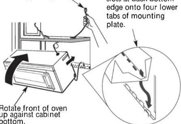
2 Rotate front of oven up against cabinet bottom.
3 Insert a self-aligning screw through top center cabinet hole. Temporarily secure the oven by turning the screw at least two full turns after the threads have engaged. (It will be completely tightened later.) Be sure to keep power cord tight. Be careful not to pinch the cord, especially when mounting flush to bottom of cabinet.

4 Attach the microwave oven to the top cabinet.
7 Tightentheoutertwoscrewstothetopofthe microwaveoven.(Whiletighteningscrews,hold themicrowaveoveninplaceagainstthewalland thetopcabinet.)

natural_image
Hand inserting a small object into a grid-patterned rectangular panel (no text or symbols visible)8 Install grease filters. See the Owner's Manual packed with the microwave.
C5. INSTALLING OR CHANGE THE CHARCOAL FILTER (Some Models)
NOTE: The charcoal filter is factory installed in some models. Refer to the Use and Care to see if yours is factory installed and for replacement information. Follow these steps to replace or install a charcoal filter.
1 Unplug microwave oven or disconnect power.
2 Open the microwave door and remove the two vent mounting screws located on top of the microwave using a #1 Phillips screwdriver.

natural_image
Line drawing of a cabinet interior with open door and window (no text or symbols)3 Tip forward. Lift out to remove.
4 Install the charcoal filter. Lay the filter on the back of the grille with the black mesh face upper.

5 Reinstall the vent by sliding the bottom of the vent into place. Push the vent top into position and slide right into place. Replace the two vent mounting screws located on top of the microwave using a #1 Phillips screwdriver.

natural_image
Architectural line drawing of a window with an open door and structural details, showing a magnified inset (no text or symbols)6 Close the microwave door. Plug in microwave oven or reconnect power.
IMPORTANT: Remove the cardhoard spacers between heat shield and door.






natural_image
Line drawing of a cabinet or oven with a door and handle (no text or symbols)LEA CUIDADOSAMENTE. CONSERVE ESTAS INSTRUCCIONES.
p/n 316495163
Augusto 2015
CONTENIDO
Información general
natural_image
Illustration of a hand holding a control panel with wires, no text or symbols presentnatural_image
Line drawing of a microwave oven with a handle and lid (no text or symbols)natural_image
Simple line drawing of a cylindrical object with a flanged top and tapered base (no text or symbols)natural_image
Technical line drawing of a structural assembly with beams and supports (no text or symbols)natural_image
Line drawing of a hand using a tool to clean or install a window (no text or symbols)natural_image
Three-panel line drawing showing a person carrying a box and another holding a document, with no visible text or symbols.natural_image
Hand inserting a small object into a grid-patterned panel (no text or symbols visible)natural_image
Technical line drawing of a structural assembly with beams and supports, no visible text or symbolsnatural_image
Line drawing of a hand using a tool to clean or store items on a kitchen appliance (no text or symbols visible)natural_image
Technical line drawing of two rectangular electronic components with internal circuitry (no text or symbols)natural_image
Technical line drawing of two rectangular electronic components with internal circuitry (no text or symbols)natural_image
Three-panel line drawing showing a person carrying a box and another holding a patient's chest, with no visible text or symbols.natural_image
Hand inserting a small object into a grid-patterned panel (no text or symbols visible)natural_image
Architectural cross-section diagram of a building facade with structural elements and floor markers (no text or labels)natural_image
Line drawing of a hand using a tool to clean or install a window (no text or symbols)natural_image
Illustration showing three scenes of a person handling a box, another with crossed-out arms, and a third holding a box (no text or symbols present)natural_image
Line drawing of a cabinet interior with doors and windows (no text or symbols)natural_image
Hand placing a button into an electrical outlet box (no text or symbols visible)2.
natural_image
Line drawing of a microwave oven with a circular vent and lid (no text or symbols)7.
natural_image
Line drawing of a cabinet or oven with a door and handle (no text or symbols)VEUILLEZ LIRE ATTENTIVEMENT.
CONSERVEZ CES INSTRUCTIONS.
INDEX:
Pièces comprises ....4
natural_image
Hand placing a button into an electrical outlet box (no text or symbols visible)défaut.
RECYCLAGE D'AIR (ÉVACUATION SANS CONDUIT)

natural_image
Line drawing of a microwave oven with a handle and lid (no text or symbols)Consultez la page 20
natural_image
Simple line drawing of a cylindrical object with a flanged top and tapered base (no text or symbols)natural_image
Technical line drawing of a structural assembly with beams and supports, no visible text or symbolsnatural_image
Line drawing of a hand using a tool to clean or install a wall-mounted device (no text or symbols visible)POUR VOTRE SÉCURITÉ ET POUR FACILITER L'INSTALLATION, L'INSTALLATION DE CE FOUR DOIT ÊTRE EFFECTUÉE PAR DEUX PERSONNES.
natural_image
Hand holding a small object over a textured surface, no text or symbols visibleA7. CONNEXION AU CONDUIT

natural_image
Architectural cross-section diagram of a building facade with structural elements and lighting fixtures (no text or labels)natural_image
Line drawing of a hand using a tool to clean or install a window (no text or symbols present)natural_image
Technical line drawing of two mechanical components with no visible text or symbolsnatural_image
Technical line drawing of two rectangular electronic components with internal circuitry (no text or symbols)natural_image
Illustration showing three scenes of people handling boxes and crossed-out items, no text or symbols presentPOUR VOTRE SÉCURITÉ ET POUR FACILITER L'INSTALLATION, L'INSTALLATION DE CE FOUR DOIT ÊTRE EFFECTUÉE PAR DEUX PERSONNES.
natural_image
Hand inserting a small object into a grid-patterned panel (no text or symbols visible)natural_image
Architectural cross-section diagram of a building facade with structural elements and floor markers (no text or labels)natural_image
Line drawing of a hand using a tool to clean or store items on a shelf (no text or symbols visible)natural_image
Hand inserting a small object into a rectangular panel (no text or symbols visible)natural_image
Line drawing of a cabinet interior with doors and windows (no text or symbols)natural_image
Architectural line drawing of a cabinet or cabinet with an open door and structural details, showing a close-up inset (no text or symbols)natural_image
Illustration of a hand inserting a grid into an electrical outlet (no text or symbols)2.
natural_image
Line drawing of a microwave oven with a circular vent and fan (no text or symbols)- CONSERVEZ LES INSTRUCTIONS D'INSTALLATION
POUR VOTRE INSPECTEUR LOCAL.

- Installation Over the Range Instructions Microwave Oven
- BEFORE YOU BEGIN
- CONTENTS
- General information
- Step-by-step installation guide
- IMPORTANT SAFETY INSTRUCTIONS
- ELECTRICAL REQUIREMENTS
- DAMAGE—SHIPMENT/ INSTALLATION
- PARTS INCLUDED
- PARTS INCLUDED (CONT.)
- TOOLS YOU WILL NEED
- Phillips screwdriver
- MOUNTING SPACE
- NOTES:
- PLACEMENT OF THE MOUNTING PLATE
- REMOVINGTHEMICROWAVE OVENFROM THECARTON/REMOVINGTHEMOUNTING PLATE
- DETERMINING WALL PLATE LOCATION UNDER YOUR CABINET
- | INSTALLATION TYPES (Choose A, B or C)
- INSTALLATION INSTRUCTIONS FOR EXTERNAL EXHAUST DUCTING
- Exhaust connection:
- Maximum duct length:
- EXTERNAL EXHAUST DUCTING
- OUTSIDE TOP EXHAUST (EXAMPLE ONLY)
- OUTSIDE BACK EXHAUST (EXAMPLE ONLY)
- A | OUTSIDE TOP EXHAUST (Vertical Duct)
- INSTALLATION OVERVIEW
- IMPORTANT NOTES:
- A2. USE TOP CABINET TEMPLATE FOR PREPARATION OF TOP CABINET
- A3. ADAPTING MICROWAVE BLOWER FOR OUTSIDE TOP EXHAUST
- A6. ADJUST THE EXHAUST ADAPTOR
- A7. CONNECTING DUCTWORK
- B | OUTSIDE BACK EXHAUST (Horizontal Duct)
- B1. PREPARING THE REAR WALL FOR OUTSIDE BACK EXHAUST
- B2. REMOVE BLOWER PLATE
- C | RECIRCULATING (Non-Vented Ductless)
- C1. ATTACH THE MOUNTING PLATE TO THE WALL
- C2. USE TOP CABINET TEMPLATE FOR PREPARATION OF TOP CABINET
- C3. CHECK BLOWER PLATE
- C5. INSTALLING OR CHANGE THE CHARCOAL FILTER (Some Models)
- CONTENIDO
- Información general
- 2.
- 7.
- INDEX:
- RECYCLAGE D'AIR (ÉVACUATION SANS CONDUIT)
- A7. CONNEXION AU CONDUIT
Brand : FRIGIDAIRE
Model : FPBM307NTF
Category : Microwave