
AR12TXHQASIN - Air-conditioner SAMSUNG - Free user manual and instructions
Find the device manual for free AR12TXHQASIN SAMSUNG in PDF.


| Product Type | Split Air Conditioner |
| Model | AR12TXHQASIN |
| Brand | Samsung |
| Cooling Capacity | 12000 BTU (3.5 kW) |
| Heating Capacity | 12000 BTU (3.5 kW) |
| Energy Efficiency Ratio (EER) | 12.0 |
| Refrigerant Type | R-32 |
| Indoor Unit Dimensions (WxHxD) | 820 x 285 x 210 mm |
| Outdoor Unit Dimensions (WxHxD) | 720 x 548 x 265 mm |
| Indoor Unit Weight | 9.5 kg |
| Outdoor Unit Weight | 26.5 kg |
| Power Supply | 230 V / 50 Hz |
| Airflow Rate (Indoor) | 550 m³/h |
| Noise Level Indoor (Low/High) | 20 / 38 dB(A) |
| Noise Level Outdoor | 49 dB(A) |
| Operating Temperature Range (Cooling) | 16°C to 46°C |
| Operating Temperature Range (Heating) | -10°C to 24°C |
| Functions | Auto, Cool, Heat, Dry, Fan, Sleep, Timer, Turbo |
| Filter Type | Washable, Anti-Bacterial |
| Maintenance | Clean filter every 2 weeks; professional cleaning annually |
| Safety Features | Auto restart, overheat protection, child lock |
| Warranty | 2 years parts and labor |
Frequently Asked Questions - AR12TXHQASIN SAMSUNG
User questions about AR12TXHQASIN SAMSUNG
0 question about this device. Answer the ones you know or ask your own.
Ask a new question about this device
Download the instructions for your Air-conditioner in PDF format for free! Find your manual AR12TXHQASIN - SAMSUNG and take your electronic device back in hand. On this page are published all the documents necessary for the use of your device. AR12TXHQASIN by SAMSUNG.
USER MANUAL AR12TXHQASIN SAMSUNG
User manual/Installation manual
AR09TXHQASINEU AR09TXHQBWKNEU AR12TXHQASINEU AR12TXHQBWKNEU AR18TXHQASINEU AR18TXHQBWKNEU AR24TXHQASINEU AR24TXHQBWKNEU
- Thank you for purchasing this Samsung air conditioner.
- Before operating this unit, please read this manual carefully and retain it for future reference.
English
Italian
Hungarian
Greek
Table of Contents
Safety Precautions....03
User manual
Unit Specifications and Features 10
- Indoor unit display ....10
- Operating temperature ......11
- Other features ...... 12
- Setting angle of airflow 13
- Manual operation (without Remote)....13
Care and Maintenance....14
Troubleshooting....16
Installation Manual
Accessories....19
Installation Summary - Indoor Unit....20
Unit Parts....21
Indoor Unit Installation....22
- Select installation location....22
- Attach mounting plate to wall 22
- Drill wall hole for connective piping 23
- Prepare refrigerant piping ....24
- Connect drain hose 24
- Connect signal cable 26
- Wrap piping and cables 27
- Mount indoor unit 28
Outdoor Unit Installation 29
- Select installation location....29
- Install drain joint ....30
- Anchor outdoor unit 30
- Connect signal and power cables ....32
Refrigerant Piping Connection 33
A. Note on Pipe Length 33
B. Connection Instructions – Refrigerant Piping 33
1. Cut pipe 33
2. Remove burrs 34
3. Flare pipe ends....34
4. Connect pipes 34
Air Evacuation....36
- Evacuation Instructions ....36
- Note on Adding Refrigerant ....37
Electrical and Gas Leak Checks....39
Test Run 39
Safety Precautions
Read Safety Precautions Before Operation and Installation Incorrect installation due to ignoring instructions can cause serious damage or injury.
The seriousness of potential damage or injuries is classified as either a WARNING or CAUTION.

WARNING
This symbol indicates the possibility of personnel injury or loss of life.

CAUTION
This symbol indicates the possibility of property damage or serious consequences.

WARNING
This appliance can be used by children aged from 8 years and above and persons with reduced physical, sensory or mental capabilities or lack of experience and knowledge if they have been given supervision or instruction concerning use of the appliance in a safe way and understand the hazards involved. Children shall not play with the appliance. Cleaning and user maintenance shall not be made by children without supervision (EN Standard requirements).
This appliance is not intended for use by persons (including children) with reduced physical, sensory or mental capabilities, or lack of experience and knowledge, unless they have been given supervision or instruction concerning use of the appliance by a person responsible for their safety. Children should be supervised to ensure that they do not play with the appliance (IEC Standard requirements).
The air conditioner should be used only for the applications for which it has been designed: the indoor unit is not suitable to be installed in areas used for laundry.

WARNINGS FOR PRODUCT USE
- If an abnormal situation arises (like a burning smell), immediately turn off the unit and disconnect the power. Call your dealer for instructions to avoid electric shock, fire or injury.
- Do not insert fingers, rods or other objects into the air inlet or outlet. This may cause injury, since the fan may be rotating at high speeds.
- Do not use flammable sprays such as hair spray, lacquer or paint near the unit. This may cause fire or combustion.
- Do not operate the air conditioner in places near or around combustible gases. Emitted gas may collect around the unit and cause explosion.
- Do not operate your air conditioner in a wet room such as a bathroom or laundry room. Too much exposure to water can cause electrical components to short circuit.
- Do not expose your body directly to cool air for a prolonged period of time.
- Do not allow children to play with the air conditioner. Children must be supervised around the unit at all times.
- If the air conditioner is used together with burners or other heating devices, thoroughly ventilate the room to avoid oxygen deficiency.
- In certain functional environments, such as kitchens, server rooms, etc., the use of specially designed air-conditioning units is highly recommended.
- Do not use means to accelerate the defrost operation or to clean, other than those recommended by Samsung.
- Do not pierce or burn.
- Be aware that refrigerants may not contain an odour.
CLEANING AND MAINTENANCE WARNINGS
- Turn off the device and disconnect the power before cleaning. Failure to do so can cause electrical shock.
Do not clean the air conditioner with excessive amounts of water.
Do not clean the air conditioner with combustible cleaning agents. Combustible cleaning agents can cause fire or deformation.
- The product shall be stored in a room with no ignition sources (e.g. open flames, gas appliance, electric heater, etc.).
- Note that the refrigerant has no odour.
- Please cover the air conditioner with PE BAG after installation, and remove it when you start to run air conditioner.

CAUTION
- Turn off the air conditioner and disconnect the power if you are not going to use it for a long time.
- Turn off and unplug the unit during storms.
- Make sure that water condensation can drain unhindered from the unit.
Do not operate the air conditioner with wet hands. This may cause electric shock.
Do not use device for any other purpose than its intended use.
Do not climb onto or place objects on top of the outdoor unit.
Do not allow the air conditioner to operate for long periods of time with doors or windows open, or if the humidity is very high.

ELECTRICAL WARNINGS
- Only use the specified power cord. If the power cord is damaged, it must be replaced by the manufacturer, its service agent or similarly qualified persons in order to avoid a hazard. - Keep power plug clean. Remove any dust or grime that accumulates on or around the plug. Dirty plugs can cause fire or electric shock.
Do not pull power cord to unplug unit. Hold the plug firmly and pull it from the outlet. Pulling directly on the cord can damage it, which can lead to fire or electric shock.
Do not modify the length of the power supply cord or use an extension cord to power the unit.
Do not share the electrical outlet with other appliances. Improper or insufficient power supply can cause fire or electrical shock.
- The product must be properly grounded at the time of installation, or electrical shock may occur.
- For all electrical work, follow all local and national wiring standards, regulations, and the Installation Manual. Connect cables tightly, and clamp them securely to prevent external forces from damaging the terminal. Improper electrical connections can overheat and cause fire, and may also cause shock. All electrical connections must be made according to the Electrical Connection Diagram located on the panels of the indoor and outdoor units.
- All wiring must be properly arranged to ensure that the control board cover can close properly. If the control board cover is not closed properly, it can lead to corrosion and cause the connection points on the terminal to heat up, catch fire, or cause electrical shock.
- If connecting power to fixed wiring, an all-pole disconnection device which has at least 3mm clearances in all poles, and have a leakage current that may exceed 10mA, the residual current device (RCD) having a rated residual operating current not exceeding 30mA, and disconnection must be incorporated in the fixed wiring in accordance with the wiring rules.
TAKE NOTE OF FUSE SPECIFICATIONS
The air conditioner's circuit board (PCB) is designed with a fuse to provide overcurrent protection.
The specifications of the fuse are printed on the circuit board, such as:
Indoor unit: T3.15AL/250VAC, T5AL/250VAC, T3.15A/250VAC, T5A/250VAC, etc.
Outdoor unit: T20A/250VAC (<=18000Btu/h units), T30A/250VAC (>18000Btu/h units)
NOTE: For the units with R32 or R290 refrigerant, only the blast-proof ceramic fuse can be used.

WARNINGS FOR PRODUCT INSTALLATION
- Installation must be performed by an authorized dealer or specialist. Defective installation can cause water leakage, electrical shock, or fire.
- Installation must be performed according to the installation instructions. Improper installation can cause water leakage, electrical shock, or fire.
(In North America, installation must be performed in accordance with the requirement of NEC and CEC by authorized personnel only.) - Contact an authorized service technician for repair or maintenance of this unit. This appliance shall be installed in accordance with national wiring regulations.
- Only use the included accessories, parts, and specified parts for installation. Using non-standard parts can cause water leakage, electrical shock, fire, and can cause the unit to fail.
- Install the unit in a firm location that can support the unit's weight. If the chosen location cannot support the unit's weight, or the installation is not done properly, the unit may drop and cause serious injury and damage.
- Install drainage piping according to the instructions in this manual. Improper drainage may cause water damage to your home and property.
- For units that have an auxiliary electric heater, do not install the unit within 1 meter (3 feet) of any combustible materials.
- Do not install the unit in a location that may be exposed to combustible gas leaks. If combustible gas accumulates around the unit, it may cause fire.
- Do not turn on the power until all work has been completed.
- When moving or relocating the air conditioner, consult experienced service technicians for disconnection and reinstallation of the unit.
- How to install the appliance to its support, please read the information for details in "indoor unit installation" and "outdoor unit installation" sections.
- The outdoor unit shall be installed in an open space that is always ventilated.
- The local gas regulations shall be observed.
- To handle, purge, and dispose the refrigerant, or break into the refrigerant circuit, the worker should have a certificate from an industry-accredited authority.
- Do not install the indoor unit in the following areas:
- Area filled with minerals, splashed oil, or steam. It will deteriorate plastic parts, causing failure or leakage.
- Area that is close to heat sources.
- Area that produces substances such as sulfuric gas, chlorine gas, acid, and alkali. It may cause corrosion of the pipings and brazed joints.
- Area that can cause leakage of combustible gas and suspension of carbon fibers, flammable dust, or volatile flammables.
- Area where refrigerant leaks and settles.
- Area where animals may urinate on the product. Ammonia may be generated.
- Do not use the indoor unit for preservation of food items, plants, equipment, and art works. This may cause deterioration of their quality.
- Do not install the indoor unit if it has any drainage problem.
- Because your air conditioner contains R-32 refrigerant, make sure that it is installed, operated, and stored it in a room whose floor area is larger than the minimum required floor area specified in the following table:
| Wall-mounted type | |
| m(kg) A(m | ^2 ) |
| ≤1.842 No requirement | |
| 1.843 4.45 | |
| 1.9 4.58 | |
| 2.0 4.83 | |
| 2.2 5.31 | |
| 2.4 5.79 | |
| 2.6 6.39 | |
| 2.8 7.41 | |
| 3.0 8.51 | |
• m : Total refrigerant charge in the system
• A : Minimum required floor area
- IMPORTANT: it's mandatory to consider either the table above or taking into consideration the local law regarding the minimum living space of the premises.
● Minimum installation height of indoor unit is 0.6 m for floor mounted, 1.8 m for wall, 2.2 m for ceiling.
Installation of the outdoor unit
- While in installation or relocation of the product, do not mix the refrigerant with other gases including air or unspecified refrigerant. Failure to do so may cause pressure increase to result in rupture or injury.
- Do not cut or burn the refrigerant container or pipings.
- Use clean parts such as manifold gauge, vacuum pump, and charging hose for the refrigerant.
- Installation must be carried out by qualified personnel for handling the refrigerant. Additionally, reference the regulations and laws.
- Be careful not to let foreign substances (lubricating oil, refrigerant, water, etc.) enter the pipings. The application of oil or refrigerant deteriorates the pipings to result in drain leakage. For storage, securely seal their openings.
- When mechanical ventilation is required, ventilation openings shall be kept clear of obstruction.
- For disposal of the product, follow the local laws and regulations.
- Do not work in a confined place.
• The work area shall be blocked.
- The refrigerant pipings shall be installed in the position where there are no substances that may result in corrosion.
- The following checks shall be performed for installation:
- The charging amount depends on the room size.
- The ventilation devices and outlets are operating normally and are not obstructed.
- Markings and signs on the equipment shall be visible and legible.
- Upon leakage of the refrigerant, ventilate the room. When the leaked refrigerant is exposed to flame, it may cause generation of toxic gases.
• Make sure that the work area is safe from flammable substances.
- To purge air in the refrigerant, be sure to use a vacuum pump.
• Note that the refrigerant has no odour.
- The units are not explosion proof so they must be installed with no risk of explosion.
- This product contains fluorinated gases that contribute to global greenhouse effect. Accordingly, do not vent gases into the atmosphere.
- Because the working pressure for R-32 is 1.6 times higher than that for R-22, use exclusive pipings and tools specified. In case of replacing an R-22 model with an R-32 model, be sure to replace the conventional pipings and flare nuts with exclusive ones.
- The models that use the refrigerant R-32 have a different thread diameter for the charging port to prevent charging failure. Therefore, check its diameter (1/2 inch) in advance.
- Servicing shall be performed as recommended by the manufacturer. In case other skilled persons are joined for servicing, it shall be carried out under supervision of the person who is competent in handling flammable refrigerants.
- For servicing the units containing flammable refrigerants, safety checks are required to minimise the risk of ignition.
- Servicing shall be performed following the controlled procedure to minimize the risk of flammable refrigerant or gases.
- Do not install where there is a risk of combustible gas leakage.
- Do not place heat sources.
-
Be cautious not to generate a spark as follows:
-
Do not remove the fuses with power on.
- Do not disconnect the power plug from the wall outlet with power on.
-
It is recommended to locate the outlet in a high position. Place the cords so that they are not tangled.
-
If the indoor unit is not R-32 compatible, an error signal appears and the unit will not operate.
- After installation, check for leakage. Toxic gas may be generated and if it comes into contact with an ignition source such as fan heater, stove, and cooker. cylinders, make sure that only the refrigerant recovery cylinders are used.
Note about Fluorinated Gasses (Not applicable to the unit using Refrigerant)
- This air-conditioning unit contains fluorinated greenhouse gasses. For specific information on the type of gas and the amount, please refer to the relevant label on the unit itself or the "Owner's Manual - Product Fiche" in the packaging of the outdoor unit. (European Union products only).
- Installation, service, maintenance and repair of this unit must be performed by a certified technician.
- Product uninstallation and recycling must be performed by a certified technician.
- For equipment that contains fluorinated greenhouse gases in quantities of 5 tonnes of CO_2 equivalent or more, but of less than 50 tonnes of CO_2 equivalent, If the system has a leak-detection system installed, it must be checked for leaks at least every 24 months.
- When the unit is checked for leaks, proper record-keeping of all checks is strongly recommended.
- When the air conditioner does not operate properly for cooling or heating, there is a possibility of refrigerant leakage. If any leakage, stop operation, ventilate the room, and consult your dealer immediately for recharging refrigerant.
- The refrigerant is not harmful. However, if it comes in contact with fire, it may generate harmful gases and there is risk of fire.
- During transportation of the indoor unit, the pipe lines shall be covered with brackets for protection. Do not move the product with holding the pipe lines.
- It may cause gas leakage.
- Do not cut or burn the refrigerant container or pipings.
- Do not point the air direction to the fireplace or heater.

WARNING for Using R32 Refrigerant
- When flammable refrigerant are employed, appliance shall be stored in a well -ventilated area where the room size corresponds to the room area as specific for operation.
For R32 frigerant models:
Appliance shall be installed, operated and stored in a room with a floor area larger than 4m^2 . Appliance shall not be installed in an unvertilated space, if that space is smaller than 4m^2 .
- Reusable mechanical connectors and flared joints are not allowed indoors. (EN Standard Requirements).
- Mechanical connectors used indoors shall have a rate of not more than 3g/year at 25% of the maximum allowable pressure. When mechanical connectors are reused indoors, sealing parts shall be renewed. When flared joints are reused indoors, the flare part shall be re-fabricated. (UL Standard Requirements)
- When mechanical connectors are reused indoors, sealing parts shall be renewed. When flared joints are reused indoors, the flare part shall be re-fabricated.
(IEC Standard Requirements)
- For the product that uses the R-32 refrigerant, Install the indoor unit on the wall 1.8 m or higher from the floor.
Preparation of fire extinguisher
- If a hot work is to be done, an appropriate fire extinguishing equipment should have been available.
- A dry powder or CO₂ fire extinguisher shall be equipped near the charging area.
Ignition sources free
- Make sure to store the units in a place without continuously operating ignition sources (for example, open flames, an operating gas appliance or an operating electric heater).
- The service engineers shall not use any ignition sources with the risk of fire or explosion.
- Potential ignition sources shall be kept away from the work area where the flammable refrigerant can possibly be released to the surrounding.
- The work area should be checked to ensure that there are no flammable hazards or ignition risks. The “No Smoking” sign shall be attached.
- Under no circumstances shall potential sources of ignition be used while in detection of leakage.
- Make sure that the seals or sealing materials have not degraded.
- Safe parts are the ones with which the worker can work in a flammable atmosphere. Other parts may result in ignition due to leakage.
- Replace components only with parts specified by Samsung. Other parts may result in the ignition of refrigerant in the atmosphere from a leak.
Area ventilation
- Make sure that the work area is well ventilated before performing a hot work.
- Ventilation shall be made even during the work.
- The ventilation should safely disperse any released gases and preferably expel them into the atmosphere.
- Ventilation shall be made even during the work.
Leakage detection methods
- The leakage detector shall be calibrated in a refrigerant-free area.
- Make sure that the detector is not a potential source of ignition.
- The leakage detector shall be set to the LFL (lower flammability limit).
- The use of detergents containing chlorine shall be avoided for cleaning because the chlorine may react with the refrigerant and corrode the pipings.
- If leakage is suspected, naked flames shall be removed.
- If a leakage is found while in brazing, the entire refrigerant shall be recovered from the product or isolated (e.g. using shut-off valves). It shall not be directly released to the environment. Oxygen free nitrogen (OFN) shall be used for purging the system before and during the brazing process.
- The work area shall be checked with an appropriate refrigerant detector before and during work.
- Ensure that the leakage detector is appropriate for use with flammable refrigerants.
Labelling
- The parts shall be labelled to ensure that they have been decommissioned and emptied of refrigerant.
- The labels shall be dated.
- Make sure that the labels are affixed on the system to notify it contains flammable refrigerant.
Recovery
- When removing refrigerant from the system for servicing or decommissioning, it is recommended to remove the entire refrigerant.
- When transferring refrigerant into cylinders, make sure that only the refrigerant recovery cylinders are used.
- All cylinders used for the recovered refrigerant shall be labelled.
- Cylinders shall be equipped with pressure relief valves and shut-off valves in a proper order.
- Empty recovery cylinders shall be evacuated and cooled before recovery.
- The recovery system shall operate normally according to the specified instructions and shall be suitable for refrigerant recovery.
- In addition, the calibration scales shall operate normally.
- Hoses shall be equipped with leak-free disconnect couplings.
- Before starting the recovery, check for the status of the recovery system and sealing state. Consult with the manufacturer if suspected.
- The recovered refrigerant shall be returned to the supplier in the correct recovery cylinders with the Waste Transfer Note attached.
- Do not mix refrigerants in the recovery units or cylinders.
- If compressors or compressor oils are to be removed, make sure that they have been evacuated to the acceptable level to ensure that flammable refrigerant does not remain in the lubricant.
- The evacuation process shall be performed before sending the compressor to the suppliers.
- Only the electrical heating to the compressor body is allowed to accelerate the process.
- Oil shall be drained safely from the system.
- For installation with handling the refrigerant (R-32), use dedicated tools and piping materials. Because the pressure of the refrigerant, R-32 is approximately 1.6 times higher than that of R-22, failure to use the dedicated tools and piping materials may cause rupture or injury. Furthermore, it may cause serious accidents such as water leakage, electric shock, or fire.
- Never install a motor-driven equipment to prevent ignition.
- In case of a malfunction, immediately stop operation of the air conditioner and disconnect the entire power system. Then consult the authorized service personnel.
Correct Disposal of This Product (Waste Electrical & Electronic Equipment)
(Applicable in countries with separate collection systems)
This marking on the product, accessories or literature indicates that the product and its electronic accessories (e.g. charger, headset, USB cable) should not be disposed of with other household waste at the end of their working life. To prevent possible harm to the environment or human health from uncontrolled waste disposal, please separate these items from other types of waste and recycle them responsibly to promote the sustainable reuse of material resources.
Household users should contact either the retailer where they purchased this product, or their local government office, for details of where and how they can take these items for environmentally safe recycling.
Business users should contact their supplier and check the terms and conditions of the purchase contract. This product and its electronic accessories should not be mixed with other commercial wastes for disposal.

Correct disposal of batteries in this product
This marking on the battery, manual or packaging indicates that the batteries in this product should not be disposed of with other household waste at the end of their working life. Where marked, the chemical symbols Hg, Cd or Pb indicate that the battery contains mercury, cadmium or lead above the reference levels in EC Directive 2006/66.
Unit Specifications and Features
Indoor unit display
NOTE: Different models have different front panel and display window. Not all the indicators describing below are available for the air conditioner you purchased. Please check the indoor display window of the unit you purchased.
Illustrations in this manual are for explanatory purposes. The actual shape of your indoor unit may be slightly different. The actual shape shall prevail.
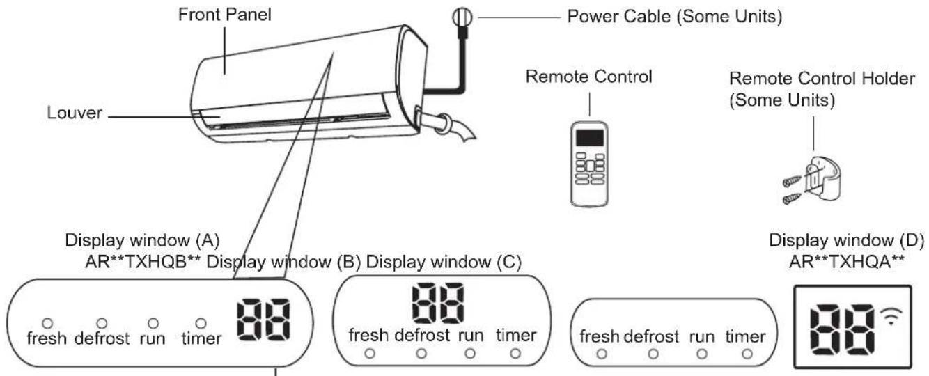
"fresh" when Fresh feature is activated (some units)
"defrost" when defrost feature is activated.
"run" when the unit is on.
"timer" when TIMER is set
“ ” when Wireless Control feature is activated (some units)
"88 Displays temperature, operation feature and Error codes:
When ECO function (some units) is activated, the
'illuminates gradually one by one as -£ [
-- 0--set temperature -- E..... in one second interval.
“ ” for 3 seconds when:
- TIMER ON is set (if the unit is OFF, ON" remains on when TIMER ON is set)
- FRESH, SWING, TURBO, or SILENCE feature is turned on "F" for 3 seconds when:
- TIMER OFF is set
- FRESH, SWING, TURBO, or SILENCE feature is turned off
“ c”F when anti-cold air feature is turned on
“df when defrosting (cooling & heating units)
“5C when unit is self-cleaning (some units)
“FP when 8°C heating feature is turned on (some units)
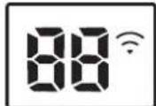
Display Code Meanings
Operating temperature
When your air conditioner is used outside of the following temperature ranges, certain safety protection features may activate and cause the unit to disable.
Inverter Split Type
| COOL mode HEAT mode DRY mode | |||
| Room Temperature | 17°C - 32°C(62°F - 90°F) | 0°C - 30°C(32°F - 86°F) | 10°C - 32°C(50°F - 90°F) |
| Outdoor Temperature | 0°C - 50°C(32°F - 122°F) | -15°C - 30°C(5°F - 86°F) | 0°C - 50°C(32°F - 122°F) |
| -15°C - 50°C(5°F - 122°F)(For models with low temp. cooling systems.) | |||
| 0°C - 52°C(32°F - 126°F)(For special tropical models) | 0°C - 52°C(32°F - 126°F)(For special tropical models) | ||
FOR OUTDOOR UNITS WITH AUXILIARY ELECTRIC HEATER
When outside temperature is below 0^ C ( 32^ F), we strongly recommend keeping the unit plugged in at all time to ensure smooth ongoing performance.
To further optimize the performance of your unit, do the following:
- Keep doors and windows closed.
- Limit energy usage by using TIMER ON and TIMER OFF functions.
- Do not block air inlets or outlets.
- Regularly inspect and clean air filters.
A guide on using the infrared remote is not included in this literature package. Not all the functions are available for the air conditioner, please check the indoor display and remote control of the unit you purchased.
Other Features
• Auto-Restart (some units)
If the unit loses power, it will automatically restart with the prior settings once power has been restored.
• Anti-mildew (some units)
When turning off the unit from COOL, AUTO (COOL), or DRY modes, the air conditioner will continue operate at very low power to dry up condensed water and prevent mildew growth.
- Wireless Control (some units)
Wireless control allows you to control your air conditioner using your mobile phone and a wireless connection.
For the USB device access, replacement, maintenance operations must be carried out by professional staff.
- Louver Angle Memory (some units)
When turning on your unit, the louver will automatically resume its former angle.
- Refrigerant Leakage Detection (some units)
The indoor unit will automatically display "EC" or "EL0C" or flash LEDs (model dependent) when it detects refrigerant leakage.
- Sleep Operation
The SLEEP function is used to decrease energy use while you sleep (and don't need the same temperature settings to stay comfortable). This function can only be activated via remote control. And the Sleep function is not available in FAN or DRY mode.
Press the SLEEP button when you are ready to go to sleep. When in COOL mode, the unit will increase the temperature by 1^ C ( 2^ F) after 1 hour, and will increase an additional 1^ C ( 2^ F) after another hour.
When in HEAT mode, the unit will decrease the temperature by 1^ C ( 2^ F) after 1 hour, and will decrease an additional 1^ C ( 2^ F) after another hour.
The sleep feature will stop after 8 hours and the system will keep running with final situation.
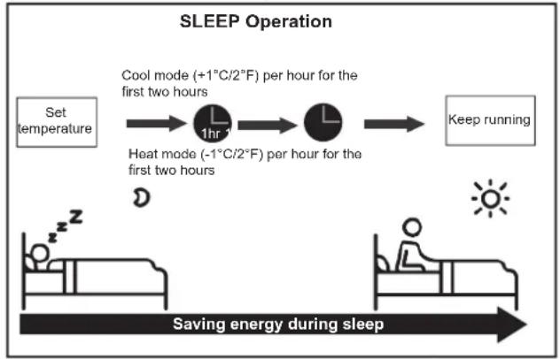
flowchart
graph LR
    A["Set temperature"] --> B["Cool mode (+1°C/2°F) per hour for the first two hours"]
    B --> C["Heat mode (-1°C/2°F) per hour for the first two hours"]
    C --> D["Keep running"]
    E["Saving energy during sleep"] --> F["Bed with sun icon"]
- Setting Angle of Air Flow
Setting vertical angle of air ow
While the unit is on, use the SWING/DIRECT button on remote control to set the direction (vertical angle) of airflow. Please refer to the Remote Control Manual for details.
NOTE ON LOUVER ANGLES
When using COOL or DRY mode, do not set louver at too vertical an angle for long periods of time. This can cause water to condense on the louver blade, which will drop on your floor or furnishings.
When using COOL or HEAT mode, setting the louver at too vertical an angle can reduce the performance of the unit due to restricted air flow.
Setting horizontal angle of air flow
The horizontal angle of the airflow must be set manually. Grip the deflector rod (See Fig.B) and manually adjust it to your preferred direction.
For some units, the horizontal angle of the airflow can be set by remote control. please refer to the Remote Control Manual.
Manual Operation (without remote)

CAUTION
The manual button is intended for testing purposes and emergency operation only. Please do not use this function unless the remote control is lost and it is absolutely necessary. To restore regular operation, use the remote control to activate the unit. Unit must be turned off before manual operation.
To operate your unit manually:
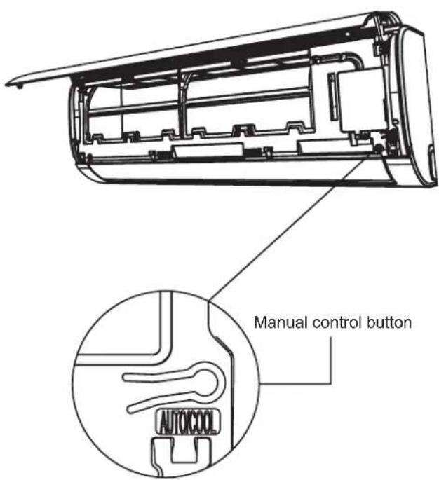
- Open the front panel of the indoor unit.
- Locate the MANUAL CONTROL button on the right-hand side of the unit.
- Press the MANUAL CONTROL button one time to activate FORCED AUTO mode.
- Press the MANUAL CONTROL button again to activate FORCED COOLING mode.
- Press the MANUAL CONTROL button a third time to turn the unit off.
- Close the front panel.
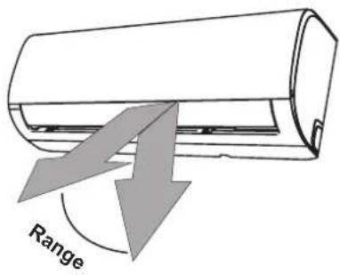
NOTE: Do not move louver by hand. This will cause the louver to become out of sync. If this occurs, turn off the unit and unplug it for a few seconds, then restart the unit. This will reset the louver.
Fig. A

CAUTION
Do not put your fingers in or near the blower and suction side of the unit. The high-speed fan inside the unit may cause injury.
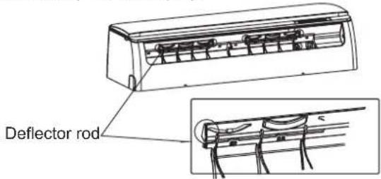
Fig. B
Care and Maintenance
Cleaning Your Indoor Unit

BEFORE CLEANING OR MAINTENANCE
ALWAYS TURN OFF YOUR AIR CONDITIONER SYSTEM AND DISCONNECT ITS POWER SUPPLY BEFORE CLEANING OR MAINTENANCE.

CAUTION
Only use a soft, dry cloth to wipe the unit clean. If the unit is especially dirty, you can use a cloth soaked in warm water to wipe it clean.
Do not use chemicals or chemically treated cloths to clean the unit
Do not use benzene, paint thinner, polishing powder or other solvents to clean the unit. They can cause the plastic surface to crack or deform.
Do not use water hotter than 40^ C ( 104^ F) to clean the front panel. This can cause the panel to deform or become discolored.
Cleaning Your Air Filter
A clogged air conditioner can reduce the cooling efficiency of your unit, and can also be bad for your health. Make sure to clean the filter once every two weeks.
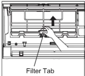
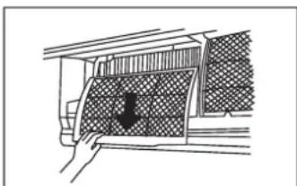
- Lift the front panel of the indoor unit.
- First press the tab on the end of filter to loosen the buckle, lift it up, then pull it towards yourself.
- Now pull the filter out.
- If your filter has a small air freshening filter, unclip it from the larger filter. Clean this air freshening filter with a hand-held vacuum.
-
Clean the large air filter with warm, soapy water. Be sure to use a mild detergent.
-
Rinse the filter with fresh water, then shake off excess water.
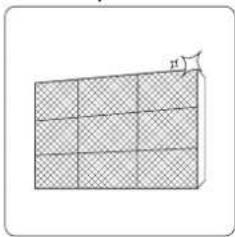
- Dry it in a cool, dry place, and refrain from exposing it to direct sunlight.
- When dry, re-clip the air freshening filter to the larger filter, then slide it back into the indoor unit.
- Close the front panel of the indoor unit.
natural_image
Line drawing of a car interior with a hand interacting with the window (no text or symbols)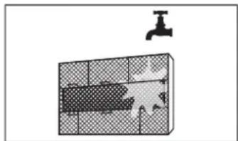
natural_image
Diagram of a bathroom sink with a faucet and patterned tile (no text or symbols)
CAUTION
- Before changing the filter or cleaning, turn off the unit and disconnect its power supply.
- When removing filter, do not touch metal parts in the unit. The sharp metal edges can cut you.
- Do not use water to clean the inside of the indoor unit. This can destroy insulation and cause electrical shock.
- Do not expose filter to direct sunlight when drying. This can shrink the filter.

CAUTION
- Any maintenance and cleaning of outdoor unit should be performed by an authorized dealer or a licensed service provider.
- Any unit repairs should be performed by an authorized dealer or a licensed service provider.
Maintenance – Long Periods of Non-Use
If you plan not to use your air conditioner for an extended period of time, do the following:
natural_image
3D grid diagram with hatched fill and a small arrow labeled 'n' pointing to the top-right corner (no text or symbols beyond basic geometry)Clean all filters
natural_image
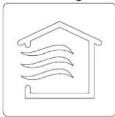
Simple line drawing of a house with wavy lines inside, no text or symbols presentTurn on FAN function until unit dries out completely
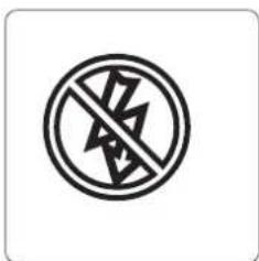
Turn off the unit and disconnect the power
natural_image
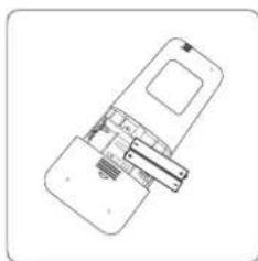
Technical line drawing of a mechanical assembly or device with no visible text or symbolsRemove batteries from remote control
Maintenance – Pre-Season Inspection
After long periods of non-use, or before periods of frequent use, do the following:
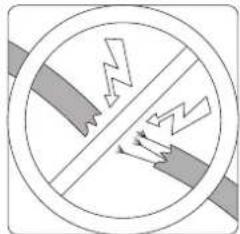
Check for damaged wires
natural_image
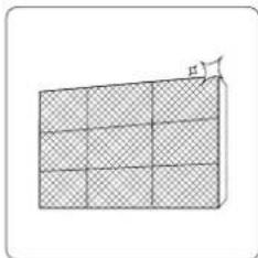
Diagram of a 3D grid structure with a labeled dimension 'h' (no text or symbols beyond the label)Clean all filters
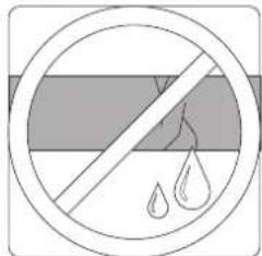
Check for leaks
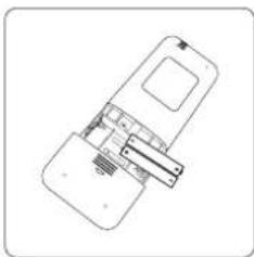
natural_image
Line drawing of a mechanical device with no visible text or symbolsReplace batteries
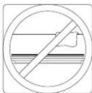
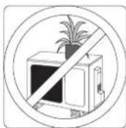
Make sure nothing is blocking all air inlets and outlets
Troubleshooting

SAFETY PRECAUTIONS
If ANY of the following conditions occurs, turn off your unit immediately!
- The power cord is damaged or abnormally warm
- You smell a burning odor
• The unit emits loud or abnormal sounds - A power fuse blows or the circuit breaker frequently trips
• Water or other objects fall into or out of the unit
DO NOT ATTEMPT TO FIX THESE YOURSELF! CONTACT AN AUTHORIZED SERVICE PROVIDER IMMEDIATELY!
Common Issues
The following problems are not a malfunction and in most situations will not require repairs.
| Issue Possible Causes | |
| Unit does not turn on when pressing ON/OFF button | The Unit has a 3-minute protection feature that prevents the unit from overloading. The unit cannot be restarted within three minutes of being turned off. |
| The unit changes from COOL/HEAT mode to FAN mode | The unit may change its setting to prevent frost from forming on the unit.Once the temperature increases, the unit will start operating in the previously selected mode again. |
| The set temperature has been reached, at which point the unit turns off the compressor. The unit will continue operating when the temperature fluctuates again. | |
| The indoor unit emits white mist | In humid regions, a large temperature difference between the room's air and the conditioned air can cause white mist. |
| Both the indoor and outdoor units emit white mist | When the unit restarts in HEAT mode after defrosting, white mist may be emitted due to moisture generated from the defrosting process. |
| The indoor unit makes noises | A rushing air sound may occur when the louver resets its position. |
| A squeaking sound may occur after running the unit in HEAT mode due to expansion and contraction of the unit's plastic parts. | |
| Both the indoor unit and outdoor unit make noises | Low hissing sound during operation: This is normal and is caused by refrigerant gas flowing through both indoor and outdoor units. |
| Low hissing sound when the system starts, has just stopped running, or is defrosting: This noise is normal and is caused by the refrigerant gas stopping or changing direction. | |
| Squeaking sound: Normal expansion and contraction of plastic and metal parts caused by temperature changes during operation can cause squeaking noises. | |
| The outdoor unit makes noises | The unit will make different sounds based on its current operating mode. |
| Dust is emitted from either the indoor or outdoor unit | The unit may accumulate dust during extended periods of non-use, which will be emitted when the unit is turned on. This can be mitigated by covering the unit during long periods of inactivity. |
| The unit emits a bad odor | The unit may absorb odors from the environment (such as furniture, cooking, cigarettes, etc.) which will be emitted during operations. |
| The unit's filters have become moldy and should be cleaned. | |
| The fan of the outdoor unit does not operate | During operation, the fan speed is controlled to optimize product operation. |
| Operation is erratic, unpredictable, or unit is unresponsive | Interference from cell phone towers and remote boosters may cause the unit to malfunction.In this case, try the following:Disconnect the power, then reconnect.Press ON/OFF button on remote control to restart operation. |
NOTE: If problem persists, contact a local dealer or your nearest customer service center. Provide them with a detailed description of the unit malfunction as well as your model number.
Troubleshooting
When troubles occur, please check the following points before contacting a repair company.
| Problem | Possible Causes | Solution |
| Poor Cooling Performance | Temperature setting may be higher than ambient room temperature | Lower the temperature setting |
| The heat exchanger on the indoor or outdoor unit is dirty | Clean the affected heat exchanger | |
| The air filter is dirty Remove the filter and | clean it according to instructions | |
| The air inlet or outlet of either unit is blocked | Turn the unit off, remove the obstruction and turn it back on | |
| Doors and windows are open Make sure that all doors and windows are closed while operating the unit | ||
| Excessive heat is generated by sunlight | Close windows and curtains during periods of high heat or bright sunshine | |
| Too many sources of heat in the room (people, computers, electronics, etc.) | Reduce amount of heat sources | |
| Low refrigerant due to leak or long-term use | Check for leaks, re-seal if necessary and top off refrigerant | |
| SILENCE function is activated (optional function) | SILENCE function can lower product performance by reducing operating frequency. Turn off SILENCE function. | |
| Problem Possible Causes | Solution | |
| The unit is not working | Power failure Wait for the power to be restored | |
| The power is turned off Turn on the power. | ||
| The fuse is burned out Replace the fuse | ||
| Remote control batteries are dead Replace batteries | ||
| The Unit's 3-minute protection has been activated | Wait three minutes after restarting the unit | |
| Timer is activated Turn timer off | ||
| The unit starts and stops frequently | There's too much or too little refrigerant in the system | Check for leaks and recharge the system with refrigerant. |
| Incompressible gas or moisture has entered the system. | Evacuate and recharge the system with refrigerant | |
| The compressor is broken Replace the compressor | ||
| The voltage is too high or too low | Install a manostat to regulate the voltage | |
| Poor heating performance | The outdoor temperature is extremely low | Use auxiliary heating device |
| Cold air is entering through doors and windows | Make sure that all doors and windows are closed during use | |
| Low refrigerant due to leak or long-term use | Check for leaks, re-seal if necessary and top off refrigerant | |
| Indicator lamps continue flashing | The unit may stop operation or continue to run safely. If the indicator lamps continue to flash or error codes appear, wait for about 10 minutes. The problem may resolve itself.If not, disconnect the power, then connect it again. Turn the unit on.If the problem persists, disconnect the power and contact your nearest customer service center. | |
| Error code appears and begins with the letters as the following in the window display of indoor unit:E (x), P (x), F (x)EH (xx), EL (xx), EC (xx)PH (xx), PL (xx), PC (xx) | ||
NOTE: If your problem persists after performing the checks and diagnostics above, turn off your unit immediately and contact an authorized service center.
To perform its antimicrobial function this product has been treated with the biocide substance Silver zinc zeolite.
Accessories
The air conditioning system comes with the following accessories. Use all of the installation parts and accessories to install the air conditioner. Improper installation may result in water leakage, electrical shock and fire, or cause the equipment to fail. The items are not included with the air conditioner must be purchased separately.
| Name of Accessories Q'ty (pc) Shape | Name of Accessories | Q'ty (pc) Shape | |||
| Manual | 2-3 |  | Remote controller | 1 | [HSTG] |
| Drain joint (for cooling & heating models) | 1 | 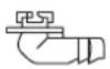 | Battery | 2 |  |
| Seal (for cooling & heating models) | 1 |  | Remote controller holder (optional) | 1 |  |
| Mounting plate | 1 | 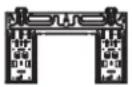 | Fixing screw for remote controller holder (optional) | 2 | |
| Anchor | 5~8 (depending on models) | 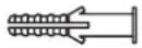 | |||
| Mounting plate fixing screw | 5~8 (depending on models) |  | |||
| Name Shape Quantity (PC) | |||
| Connecting pipe assembly | Liquid side | 6.35 (1/4 in) | Parts you must purchase separately. Consult the dealer about the proper pipe size of the unit you purchased. |
| 9.52 (3/8in) | |||
| Gas side | 9.52 (3/8in) | ||
| 12.7 (1/2in) | |||
| 15.88 (5/8in) | |||
Installation Summary - Indoor Unit
Select Installation Location
Determine Wall Hole Position
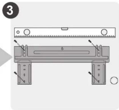
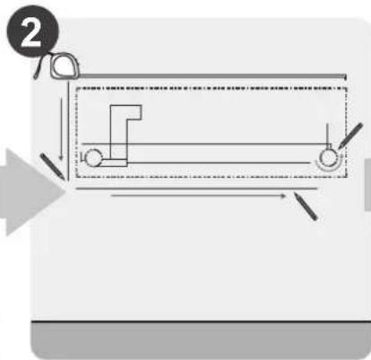
Attach Mounting Plate
natural_image
Illustration of a hand using a tool to adjust a component, with no visible text or symbols.Drill Wall Hole
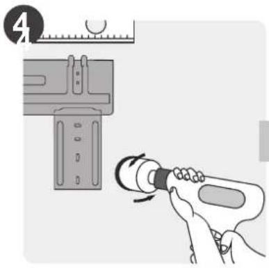
natural_image
Mechanical diagram showing a tool interacting with a bolt and nut (no text or symbols)Connect Piping
Connect Wiring (not applicable for some locations in the US )
natural_image
Illustration of hands performing a finger manipulation or tooling task on a textured surface (no text or symbols)Prepare Drain Hose
natural_image
Diagram of a cable being inserted into a wire, showing layered structure and cable arrangement (no text or symbols)Wrap Piping and Cable (not applicable for some locations in the US)
natural_image
Illustration of two hands holding a horizontal bar with three upward arrows, no text or symbols presentMount Indoor Unit
Unit Parts
NOTE: The installation must be performed in accordance with the requirement of local and national standards. The installation may be slightly different in different areas.
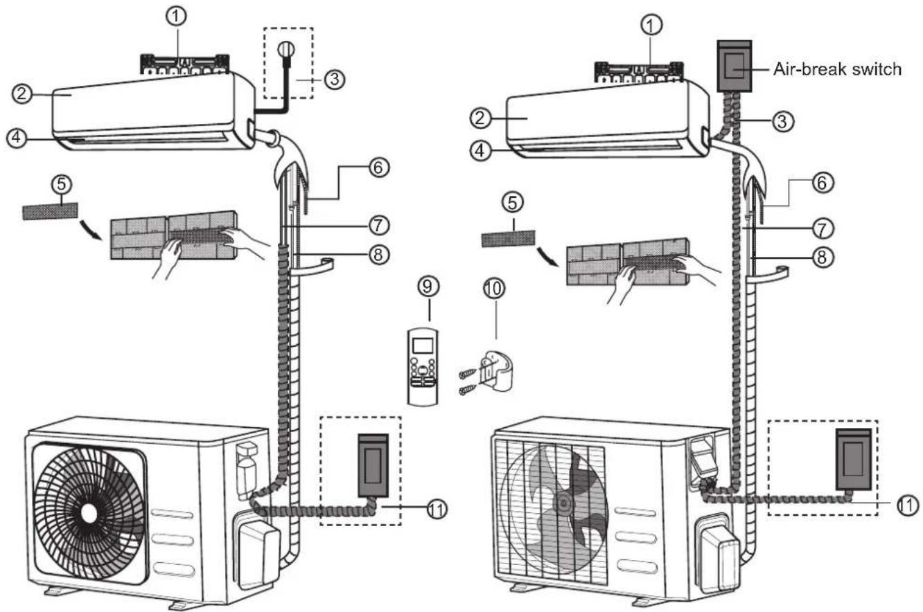
(1) (2)
① Wall Mounting Plate
②FrontPanel
③ Power Cable (Some Units)
④ Louver
⑤ Functional Filter (On Back of Main Filter - Some Units)
⑥DrainagePipe
⑦SignalCable
⑧RefrigerantPiping
⑨RemoteController
⑩ Remote controller Holder (Some Units)
⑪ Outdoor Unit Power Cable (Some Units)
NOTE ON ILLUSTRATIONS
Illustrations in this manual are for explanatory purposes. The actual shape of your indoor unit may be slightly different. The actual shape shall prevail.
Indoor Unit Installation
Installation Instructions – Indoor unit
PRIOR TO INSTALLATION
Before installing the indoor unit, refer to the label on the product box to make sure that the model number of the indoor unit matches the model number of the outdoor unit.
Step 1: Select installation location
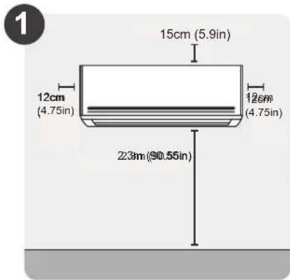
Before installing the indoor unit, you must choose an appropriate location. The following are standards that will help you choose an appropriate location for the unit.
Proper installation locations meet the following standards:
√ Good air circulation
√ Convenient drainage
√ Noise from the unit will not disturb other people
√ Firm and solid—the location will not vibrate
√ Strong enough to support the weight of the unit
A location at least one meter from all other electrical devices (e.g., TV, radio, computer)
DO NOT install unit in the following locations:
∅ Near any source of heat, steam, or combustible gas
∅ Near flammable items such as curtains or clothing
∅ Near any obstacle that might block air circulation
∅ Near the doorway
∅ In a location subject to direct sunlight
NOTE ABOUT WALL HOLE:
If there is no fixed refrigerant piping: While choosing a location, be aware that you should leave ample room for a wall hole (see Drill wall hole for connective piping step) for the signal cable and refrigerant piping that connect the indoor and outdoor units. The default position for all piping is the right side of the indoor unit (while facing the unit). However, the unit can accommodate piping to both the left and right.
Refer to the following diagram to ensure proper distance from walls and ceiling:
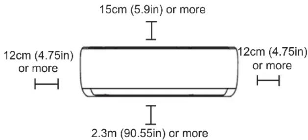
Step 2: Attach mounting plate to wall
The mounting plate is the device on which you will mount the indoor unit.
- Take out the mounting plate at the back of the indoor unit.
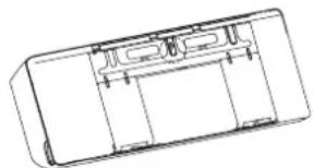
natural_image
Technical line drawing of a rectangular electronic component with internal compartments and mounting holes (no text or symbols)- Secure the mounting plate to the wall with the screws provided. Make sure that mounting plate is flat against the wall.
NOTE FOR CONCRETE OR BRICK WALLS:
If the wall is made of brick, concrete, or similar material, drill 5mm-diameter (0.2in-diameter) holes in the wall and insert the sleeve anchors provided. Then secure the mounting plate to the wall by tightening the screws directly into the clip anchors.
Step 3: Drill wall hole for connective piping
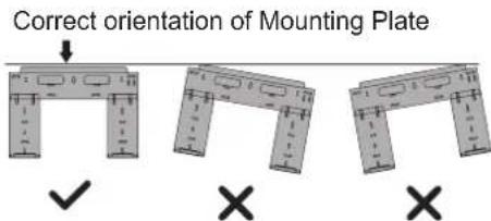
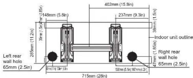
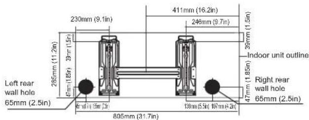
- Determine the location of the wall hole based on the position of the mounting plate. Refer to Mounting Plate Dimensions.
- Using a 65mm (2.5in) or 90mm (3.54in) (depending on models) core drill, drill a hole in the wall. Make sure that the hole is drilled at a slight downward angle, so that the outdoor end of the hole is lower than the indoor end by about 5mm to 7mm (0.2-0.275in). This will ensure proper water drainage.
- Place the protective wall cuff in the hole. This protects the edges of the hole and will help seal it when you finish the installation process.

CAUTION
When drilling the wall hole, make sure to avoid wires, plumbing, and other sensitive components.
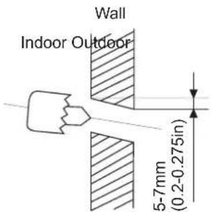
MOUNTING PLATE DIMENSIONS
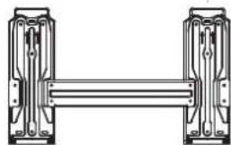
Different models have different mounting plates.
For the different customization requirements, the shape of the mounting plate may be slightly different. But the installation dimensions are the same for the same size of indoor unit.
See Type A and Type B for example:
natural_image
Pure mechanical assembly diagram showing two vertical components connected by a horizontal bar (no text or symbols)Type B
Model A
Model B
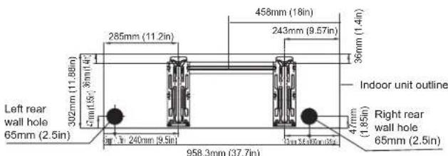
Model C
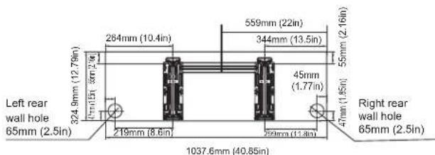
Model D
NOTE: When the gas side connective pipe is 15.88mm (5/8in) or more, the wall hole should be 90mm (3.54in).
Step 4: Prepare refrigerant piping
The refrigerant piping is inside an insulating sleeve attached to the back of the unit. You must prepare the piping before passing it through the hole in the wall.
- Based on the position of the wall hole relative to the mounting plate, choose the side from which the piping will exit the unit.
- If the wall hole is behind the unit, keep the knock-out panel in place. If the wall hole is to the side of the indoor unit, remove the plastic knock-out panel from that side of the unit. This will create a slot through which your piping can exit the unit. Use needle nose pliers if the plastic panel is too difficult to remove by hand.
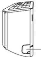
Knock-out Panel
- If existing connective piping is already embedded in the wall, proceed directly to the Connect Drain Hose step. If there is no embedded piping, connect the indoor unit's refrigerant piping to the connective piping that will join the indoor and outdoor units. Refer to the Refrigerant Piping Connection section of this manual for detailed instructions.
NOTE ON PIPING ANGLE
Refrigerant piping can exit the indoor unit from four different angles: Left-hand side, Right-hand side, Left rear, Right rear.
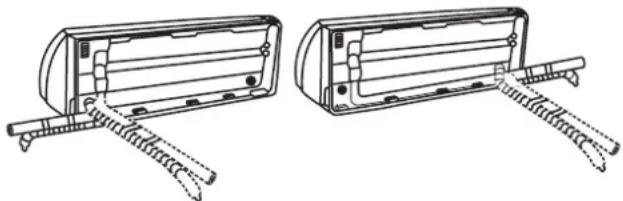
natural_image
Technical line drawing of two mechanical components with spring-loaded ends and mounting brackets (no text or symbols)CAUTION
Be extremely careful not to dent or damage the piping while bending them away from the unit. Any dents in the piping will affect the unit's performance.
- Tighten the nuts to the specified torques.
If overtightened, the nuts could be broken so refrigerant may leak.
CAUTION
- Keep the piping length at a minimum to minimize the additional refrigerant charge due to piping extension. (Maximum allowable piping length: 15 m (for **09/12*********) and 30 m (for **18/24*********))
- When connecting the pipes, make sure that surrounding objects do not interfere with or contact them to prevent refrigerant leakage due to physical damage.
- Make sure that the spaces where the refrigerant pipes are installed comply with national gas regulations.
- Be sure to perform works such as additional refrigerant charging and pipe welding under the conditions of good ventilation.
- Be sure to perform welding and piping works for mechanical connections under the conditions that the refrigerant does not circulate.
- When reconnecting the pipes, make sure to perform flared-jointing newly to prevent refrigerant leakage.
- When working on the refrigerant pipes and the flexible refrigerant connectors, be careful that they are not damaged physically by surrounding objects.
Step 5: Connect drain hose
By default, the drain hose is attached to the lefthand side of unit (when you're facing the back of the unit). However, it can also be attached to the right-hand side. To ensure proper drainage, attach the drain hose on the same side that your refrigerant piping exits the unit. Attach drain hose extension (purchased separately) to the end of drain hose.
- Wrap the connection point firmly with Teflon tape to ensure a good seal and to prevent leaks.
- For the portion of the drain hose that will remain indoors, wrap it with foam pipe insulation to prevent condensation.
- Remove the air filter and pour a small amount of water into the drain pan to make sure that water flows from the unit smoothly.
NOTE ON DRAIN HOSE PLACEMENT
Make sure to arrange the drain hose according to the following figures.
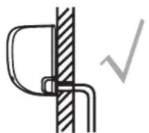
natural_image
Pure mechanical diagram showing a bracket and checkmark symbol without any text or labelsCORRECT
Make sure there are no kinks or dent in drain hose to ensure proper drainage.
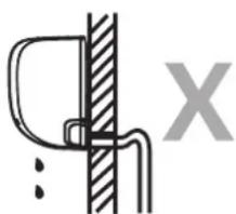
natural_image
Pure mechanical diagram showing a bracket and vertical wall with a cross symbol (no text or labels)NOT CORRECT
Kinks in the drain hose will create water traps.
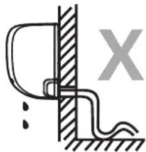
natural_image
Simple line drawing of a door and wall junction with a wavy line and a cross symbol (no text or labels)NOT CORRECT
Kinks in the drain hose will create water traps.
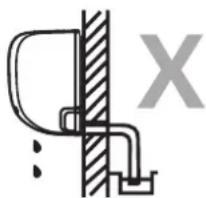
natural_image
Simple line drawing of a toilet or sink with a wall and pipe, no text or symbols presentNOT CORRECT
Do not place the end of the drain hose in water or in containers that collect water. This will prevent proper drainage.
PLUG THE UNUSED DRAIN HOLE
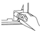
To prevent unwanted leaks you must plug the unused drain hole with the rubber plug provided.
BEFORE PERFORMING ANY ELECTRICAL WORK, READ THESE REGULATIONS
- All wiring must comply with local and national electrical codes, regulations and must be installed by a licensed electrician.
- All electrical connections must be made according to the Electrical Connection Diagram located on the panels of the indoor and outdoor units.
- If there is a serious safety issue with the power supply, stop work immediately. Explain your reasoning to the client, and refuse to install the unit until the safety
issue is properly resolved.
-
Power voltage should be within 90-110% of rated voltage. Insufficient power supply can cause malfunction, electrical shock, or fire.
-
If connecting power to fixed wiring, install a surge protector and main power switch with a capacity of 1.5 times the maximum current of the unit.
-
If connecting power to fixed wiring, a switch or circuit breaker that disconnects all poles and has a contact separation of at least 1/8in (3mm) must be incorporated in the fixed wiring. The qualified technician must use an approved circuit breaker or switch.
-
Only connect the unit to an individual branch circuit outlet. Do not connect another appliance to that outlet.
-
Make sure to properly ground the air conditioner.
-
Every wire must be firmly connected. Loose wiring can cause the terminal to overheat, resulting in product malfunction and possible fire.
-
Do not let wires touch or rest against refrigerant tubing, the compressor, or any moving parts within the unit.
-
If the unit has an auxiliary electric heater, it must be installed at least 1 meter (40in) away from any combustible materials.
-
To avoid getting an electric shock, never touch the electrical components soon after the power supply has been turned off. After turning off the power, always wait 10 minutes or more before you touch the electrical components.

WARNING
BEFORE PERFORMING ANY ELECTRICAL OR WIRING WORK, TURN OFF THE MAIN POWER TO THE SYSTEM.
Step 6: Connect signal cable
The signal cable enables communication between the indoor and outdoor units. You must first choose the right cable size before preparing it for connection.
Cable Types
- Indoor Power Cable (if applicable): H05VV-F or H05V2V2-F
• Outdoor Power Cable: H07RN-F
• Signal Cable: H07RN-F
Minimum Cross-Sectional Area of Power and Signal Cables (For reference)
| Rated Current of Appliance (A) | Nominal Cross-Sectional Area ( mm^2 ) |
| >3 and ≤ 6 0.75 | |
| >6 and ≤ 10 1 | |
| >10 and ≤ 16 1.5 | |
| >16 and ≤ 25 2.5 | |
| >25 and ≤ 32 4 | |
| >32 and ≤ 40 6 |
- For the product that uses the R-32 refrigerant, be cautious not to generate a spark by keeping the following requirements:
- Do not remove the fuses with power on.
- Do not disconnect the power plug from the wall outlet with power on.
- It is recommended to locate the outlet in a high position. Place the cords so that they are not tangled.
CHOOSE THE RIGHT CABLE SIZE
The size of the power supply cable, signal cable, fuse, and switch needed is determined by the maximum current of the unit. The maximum current is indicated on
the nameplate located on the side panel of the unit. Refer to this nameplate to choose the right cable, fuse, or switch.
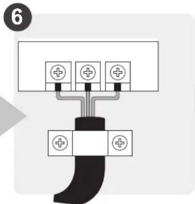
- Open front panel of the indoor unit.
- Using a screwdriver, open the wire box cover on the right side of the unit. This will reveal the terminal block.
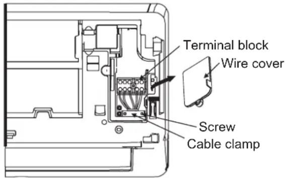

WARNING
ALL WIRING MUST BE PERFORMED STRICTLY IN ACCORDANCE WITH THE WIRING DIAGRAM LOCATED ON THE BACK OF THE INDOOR UNIT'S FRONT PANEL.
- Unscrew the cable clamp below the terminal block and place it to the side.
- Facing the back of the unit, remove the plastic panel on the bottom left-hand side.
- Feed the signal wire through this slot, from the back of the unit to the front.
- Facing the front of the unit, connect the wire according to the indoor unit's wiring diagram, connect the u-lug and firmly screw each wire to its corresponding terminal.

CAUTION
DO NOT MIX UP LIVE AND NULL WIRES
This is dangerous, and can cause the air conditioning unit to malfunction.
- After checking to make sure every connection is secure, use the cable clamp to fasten the signal cable to the unit. Screw the cable clamp down tightly.
- Replace the wire cover on the front of the unit, and the plastic panel on the back.

NOTE ABOUT WIRING
THE WIRING CONNECTION PROCESS MAY DIFFER SLIGHTLY BETWEEN UNITS AND REGIONS.
Step 7: Wrappiping and cables
Before passing the piping, drain hose, and the signal cable through the wall hole, you must bundle them together to save space, protect them, and insulate them (Not applicable in North America).
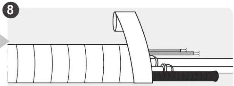
- Bundle the drain hose, refrigerant pipes, and signal cable as shown below:
Indoor Unit
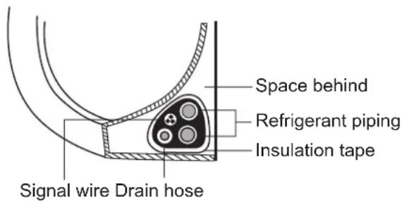
DRAIN HOSE MUST BE ON BOTTOM
Make sure that the drain hose is at the bottom of the bundle. Putting the drain hose at the top of the bundle can cause the drain pan to overflow, which can lead to fire or water damage.
DO NOT INTERTWINE SIGNAL CABLE WITH OTHER WIRES
While bundling these items together, do not intertwine or cross the signal cable with any other wiring.
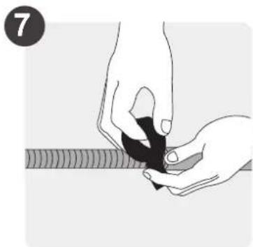
- Using adhesive vinyl tape, attach the drain hose to the underside of the refrigerant pipes.
- Using insulation tape, wrap the signal wire, refrigerant pipes, and drain hose tightly together. Double-check that all items are bundled.
DO NOT WRAP ENDS OF PIPING
When wrapping the bundle, keep the ends of the piping unwrapped. You need to access them to test for leaks at the end of the installation process (refer to Electrical Checks and Leak Checks section of this manual).
Step 8: Mount indoor unit
If you installed new connective piping to the outdoor unit, do the following:
- If you have already passed the refrigerant piping through the hole in the wall, proceed to Step 4.
- Otherwise, double-check that the ends of the refrigerant pipes are sealed to prevent dirt or foreign materials from entering the pipes.
- Slowly pass the wrapped bundle of refrigerant pipes, drain hose, and signal wire through the hole in the wall.
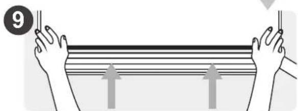
- Hook the top of the indoor unit on the upper hook of the mounting plate.
- Check that unit is hooked firmly on mounting by applying slight pressure to the left and right-hand sides of the unit. The unit should not jiggle or shift.
- Using even pressure, push down on the bottom half of the unit. Keep pushing down until the unit snaps onto the hooks along the bottom of the mounting plate.
- Again, check that the unit is firmly mounted by applying slight pressure to the left and the right-hand sides of the unit.
If refrigerant piping is already embedded in the wall, do the following:
- Hook the top of the indoor unit on the upper hook of the mounting plate.
- Use a bracket or wedge to prop up the unit, giving you enough room to connect the refrigerant piping, signal cable, and drain hose.
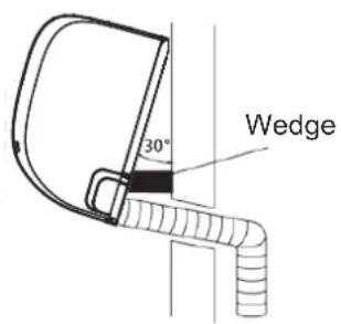
-
Connect drain hose and refrigerant piping (refer efer to Refrigerant Piping Connection section of this manual for instructions).
-
Keep pipe connection point exposed to perform the leak test (refer to Electrical Checks and Leak Checks section of this manual).
-
After the leak test, wrap the connection point with insulation tape.
-
Remove the bracket or wedge that is propping up the unit.
-
Using even pressure, push down on the bottom half of the unit. Keep pushing down until the unit snaps onto the hooks along the bottom of the mounting plate.
UNIT IS ADJUSTABLE
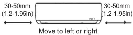
Keep in mind that the hooks on the mounting plate are smaller than the holes on the back of the unit. If you find that you don't have ample room to connect embedded pipes to the indoor unit, the unit can be adjusted left or right by about 30-50mm (1.25-1.95in), depending on the model.
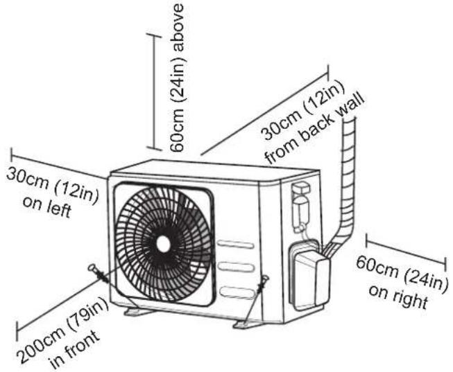
Outdoor Unit Installation
Install the unit by following local codes and regulations, there may be differ slightly between different regions.
Installation Instructions – Outdoor unit
Step 1: Select installation location
Before installing the outdoor unit, you must choose an appropriate location. The following are standards that will help you choose an appropriate location for the unit.
Proper installation locations meet the following standards:
√ Meets all spatial requirements shown in Installation Space Requirements above.
√ Good air circulation and ventilation
√ Firm and solid—the location can support the unit and will not vibrate
√ Noise from the unit will not disturb others
√ Protected from prolonged periods of direct sunlight or rain
√ Where snowfall is anticipated, raise the unit above the base pad to prevent ice buildup and coil damage. Mount the unit high enough to be above the average accumulated area snowfall. The minimum height must be 18 inches
DO NOT install unit in the following locations:
∅ Near an obstacle that will block air inlets and outlets
∅ Near a public street, crowded areas, or where noise from the unit will disturb others
∅ Near animals or plants that will be harmed by hot air discharge
∅ Near any source of combustible gas
∅ In a location that is exposed to large amounts of dust
∅ In a location exposed to a excessive amounts of salty air
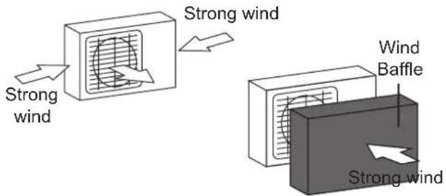
If the unit is exposed to heavy wind:
Install unit so that air outlet fan is at a 90^ angle to the direction of the wind. If needed, build a barrier in front of the unit to protect it from extremely heavy winds.
See Figures below.
If the unit is frequently exposed to heavy rain or snow:
Build a shelter above the unit to protect it from the rain or snow. Be careful not to obstruct air flow around the unit.
If the unit is frequently exposed to salty air (seaside):
Use outdoor unit that is specially designed to resist corrosion.
Step 2: Install drain joint (Heat pump unit only)
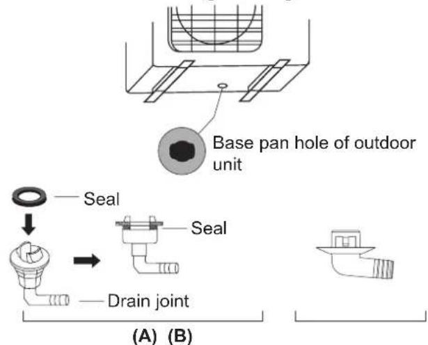
Before bolting the outdoor unit in place, you must install the drain joint at the bottom of the unit. Note that there are two different types of drain joints depending on the type of outdoor unit.
If the drain joint comes with a rubber seal (see Fig. A), do the following:
- Fit the rubber seal on the end of the drain joint that will connect to the outdoor unit.
- Insert the drain joint into the hole in the base pan of the unit.
- Rotate the drain joint 90^ until it clicks in place facing the front of the unit.
- Connect a drain hose extension (not included) to the drain joint to redirect water from the unit during heating mode.
If the drain joint doesn't come with a rubber seal (see Fig. B), do the following:
- Insert the drain joint into the hole in the base pan of the unit. The drain joint will click in place.
- Connect a drain hose extension (not included) to the drain joint to redirect water from the unit during heating mode.
! IN COLD CLIMATES
In cold climates, make sure that the drain hose is as vertical as possible to ensure swift water drainage. If water drains too slowly, it can freeze in the hose and flood the unit.
Step 3: Anchor outdoor unit
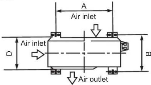
The outdoor unit can be anchored to the ground or to a wall-mounted bracket with bolt (M10). Prepare the installation base of the unit according to the dimensions below.
UNIT MOUNTING DIMENSIONS
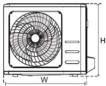
The following is a list of different outdoor unit sizes and the distance between their mounting feet. Prepare the installation base of the unit according to the dimensions below.
natural_image
Technical line drawing of a front-end air conditioner unit with fan and height dimension labeled (W, H)| Outdoor Unit Dimensions (mm)W × H × D | Mounting Dimensions | |
| Distance A (mm) D | Distance B (mm) | |
| 720 × 495 × 270 (28.3" × 19.5" × 10.6") 452 | (17.7") 255 (10.0") | |
| 800 × 554 × 333 (31.5" × 21.8" × 13.1") 514 | (20.2") 340 (13.4") | |
| 845 × 702 × 363 (33.3" × 27.6" × 14.3") 540 | (21.3") 350 (13.8") | |
If you will install the unit on the ground or on a concrete mounting platform, do the following:
- Mark the positions for four expansion bolts based on dimensions chart.
- Pre-drill holes for expansion bolts.
- Place a nut on the end of each expansion bolt.
- Hammer expansion bolts into the pre-drilled holes.
- Remove the nuts from expansion bolts, and place outdoor unit on bolts.
- Put washer on each expansion bolt, then replace the nuts.
- Using a wrench, tighten each nut until snug.

WARNING
WHEN DRILLING INTO CONCRETE, EYE PROTECTION IS RECOMMENDED AT ALL TIMES.
If you will install the unit on a wall-mounted bracket, do the following:

CAUTION
Make sure that the wall is made of solid brick, concrete, or of similarly strong material. The wall must be able to support at least four times the weight of the unit.
- Mark the position of bracket holes based on dimensions chart.
- Pre-drill the holes for the expansion bolts.
- Place a washer and nut on the end of each expansion bolt.
- Thread expansion bolts through holes in mounting brackets, put mounting brackets in position, and hammer expansion bolts into the wall.
- Check that the mounting brackets are level.
- Carefully lift unit and place its mounting feet on brackets.
- Bolt the unit firmly to the brackets.
- If allowed, install the unit with rubber gaskets to reduce vibrations and noise.
Step 4: Connect signal and power cables
The outside unit's terminal block is protected by an electrical wiring cover on the side of the unit. A comprehensive wiring diagram is printed on the inside of the wiring cover.

WARNING
BEFORE PERFORMING ANY ELECTRICAL OR WIRING WORK, TURN OFF THE MAIN POWER TO THE SYSTEM.
- Prepare the cable for connection:
USE THE RIGHT CABLE
- Indoor Power Cable (if applicable): H05VV-F or H05V2V2-F
• Outdoor Power Cable: H07RN-F
• Signal Cable: H07RN-F
CHOOSE THE RIGHT CABLE SIZE
The size of the power supply cable, signal cable, fuse, and switch needed is determined by the maximum current of the unit. The maximum current is indicated on the nameplate located on the side panel of the unit. Refer to this nameplate to choose the right cable, fuse, or switch.
a. Using wire strippers, strip the rubber jacket from both ends of cable to reveal about 40mm (1.57in) of the wires inside.
b. Strip the insulation from the ends of the wires.
c. Using a wire crimper, crimp u-lugs on the ends of the wires.
PAY ATTENTION TO LIVE WIRE
While crimping wires, make sure you clearly distinguish the Live ("L") Wire from other wires.

WARNING
ALL WIRING WORK MUST BE PERFORMED STRICTLY IN ACCORDANCE WITH THE WIRING DIAGRAM LOCATED INSIDE OF WIRE COVER OF THE OUTDOOR UNIT.
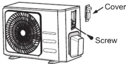
- Unscrew the electrical wiring cover and remove it.
- Unscrew the cable clamp below the terminal block and place it to the side.
- Connect the wire according to the wiring diagram, and firmly screw the u-lug of each wire to its corresponding terminal.
- After checking to make sure every connection is secure, loop the wires around to prevent rain water from flowing into the terminal.
- Using the cable clamp, fasten the cable to the unit. Screw the cable clamp down tightly.
- Insulate unused wires with PVC electrical tape. Arrange them so that they do not touch any electrical or metal parts.
- Replace the wire cover on the side of the unit, and screw it in place.
In North America
- Remove the wire cover from the unit by loosening the 3 screws.
- Dismount caps on the conduit panel.
- Temporarily mount the conduit tubes (not included) on the conduit panel.
- Properly connect both the power supply and low voltage lines to the corresponding terminals on the terminal block.
- Ground the unit in accordance with local codes.
- Be sure to size each wire allowing several inches longer than the required length for wiring.
- Use lock nuts to secure the conduit tubes.
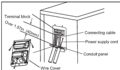
Please select the appropriate through-hole according to the diameter of the wire.
Refrigerant Piping Connection
When connecting refrigerant piping, do not let substances or gases other than the specified refrigerant enter the unit. The presence of other gases or substances will lower the unit's capacity, and can cause abnormally high pressure in the refrigeration cycle. This can cause explosion and injury.
Note on Pipe Length
The length of refrigerant piping will affect the performance and energy efficiency of the unit. Nominal efficiency is tested on units with a pipe length of 5 meters (16.5ft) to minimise vibration & excessive noise.
Refer to the table below for specifications on the maximum length and drop height of piping.
Maximum Length and Drop Height of Refrigerant Piping per Unit Model
| Model Capacity | (BTU/h) Max. Length (m) Max. Drop Height (m) | |
| R32 Inverter Split Air Conditioner | < 15,000 25 (82ft) 10 (33ft) | |
| ≥ 15,000 and < 24,000 | 30 (98.5ft) 20 (66ft) | |
| ≥ 24,000 and < 36,000 | 50 (164ft) 25 (82ft) | |
Connection Instructions – Refrigerant Piping
Step 1: Cut pipes
When preparing refrigerant pipes, take extra care to cut and flare them properly. This will ensure efficient operation and minimize the need for future maintenance.
- Measure the distance between the indoor and outdoor units.
- Using a pipe cutter, cut the pipe a little longer than the measured distance.
- Make sure that the pipe is cut at a perfect 90^ angle.
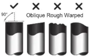

DO NOT DEFORM PIPE WHILE CUTTING
Be extra careful not to damage, dent, or deform the pipe while cutting. This will drastically reduce the heating efficiency of the unit.
Step 2: Remove burrs
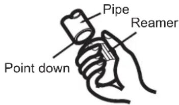
Burrs can affect the air-tight seal of refrigerant piping connection. They must be completely removed.
- Hold the pipe at a downward angle to prevent burrs from falling into the pipe.
- Using a reamer or deburring tool, remove all burrs from the cut section of the pipe.
Step 3: Flare pipe ends
Proper flaring is essential to achieve an airtight seal.
- After removing burrs from cut pipe, seal the ends with PVC tape to prevent foreign materials from entering the pipe.
- Sheath the pipe with insulating material.
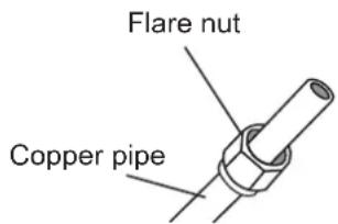
- Place flare nuts on both ends of pipe. Make sure they are facing in the right direction, because you can't put them on or change their direction after flaring.
-
Remove PVC tape from ends of pipe when ready to perform flaring work.
-
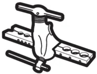
Clamp flare form on the end of the pipe. The end of the pipe must extend beyond the edge of the flare form in accordance with the dimensions shown in the table below.
natural_image
Illustration of a mechanical lever with multiple base plates and a handle (no text or symbols)PIPING EXTENSION BEYOND FLARE FORM
| Outer Diameter of Pipe (mm) | A (mm) | |
| Min. Max. | ||
| 6.35 ( 0.25") | .7 (0.0275") | 1.3 (0.05") |
| 9.52 ( 0.375") | 1.0 (0.04") 1.6 | (0.063") |
| 12.7 ( 0.5") | 1.0 (0.04") 1.8 | (0.07") |
| 15.88 ( 0.63") | 2.0 (0.078") 2 | 2 (0.086") |
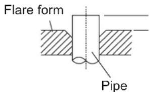
- Place flaring tool onto the form.
- Turn the handle of the flaring tool clockwise until the pipe is fully flared.
- Remove the flaring tool and flare form, then inspect the end of the pipe for cracks and even flaring.
Step 4: Connect pipes
When connecting refrigerant pipes, be careful not to use excessive torque or to deform the piping in any way. You should first connect the low-pressure pipe, then the high-pressure pipe.
MINIMUM BEND RADIUS
When bending connective refrigerant piping, the minimum bending radius is 10cm.
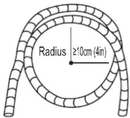
Instructions for Connecting Piping to Indoor Unit
- Align the center of the two pipes that you will connect.
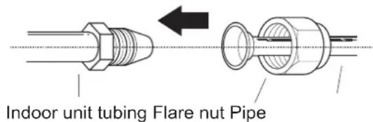
- Tighten the flare nut as tightly as possible by hand.
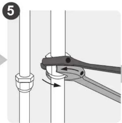
- Using a spanner, grip the nut on the unit tubing.
- While firmly gripping the nut on the unit tubing, use a torque wrench to tighten the flare nut according to the torque values in the Torque Requirements table below. Loosen the flaring nut slightly, then tighten again.
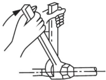
natural_image
Illustration of a hand using a tool to lift a mechanical component (no text or symbols present)TORQUE REQUIREMENTS
| Outer Diameter of Pipe (mm) | Tightening Torque (N·m) | Flare dimension (B) (mm) | Flare shape |
| 6.35 ( 0.25") 18 | ~20 (180~200kgf.cm) 8.4~8 | 7 (0.33~0.34") | 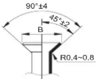 |
| 9.52 ( 0.375") 32 | ~39 (320~390kgf.cm) 13.2~ | 13.5 (0.52~0.53") | |
| 12.7 ( 0.5") 49 | 59 (490~590kgf.cm) 16.2~ | 6.5 (0.64~0.65") | |
| 15.88 ( 0.63") 57 | ~71 (570~710kgf.cm) 19.2~ | 19.7 (0.76~0.78") |
DO NOT USE EXCESSIVE TORQUE
Excessive force can break the nut or damage the refrigerant piping. You must not exceed torque requirements shown in the table above.
Instructions for Connecting Piping to Outdoor Unit
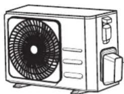
- Unscrew the cover from the packed valve on the side of the outdoor unit.
- Remove protective caps from ends of valves.
- Align flared pipe end with each valve, and tighten the flare nut as tightly as possible by hand.
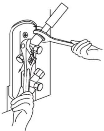
- Using a spanner, grip the body of the valve. Do not grip the nut that seals the service valve.
natural_image
Line drawing of a rectangular air conditioner unit with fan and vent slots (no text or symbols)Valve cover
-
While firmly gripping the body of the valve, use a torque wrench to tighten the flare nut according to the correct torque values.
-
Loosen the flaring nut slightly, then tighten again.
- Repeat Steps 3 to 6 for the remaining pipe.
USE SPANNER TO GRIP MAIN BODY OF VALVE
Torque from tightening the flare nut can snap off other parts of valve.
natural_image
Line drawing of hands using a tool to adjust or install a mechanical component (no text or symbols present)Air Evacuation
Preparations and Precautions
Air and foreign matter in the refrigerant circuit can cause abnormal rises in pressure, which can damage the air conditioner, reduce its efficiency, and cause injury. Use a vacuum pump and manifold gauge to evacuate the refrigerant circuit, removing any non-condensable gas and moisture from the system.
Evacuation should be performed upon initial installation and when unit is relocated.
BEFORE PERFORMING EVACUATION
√ Check to make sure the connective pipes between the indoor and outdoor units are connected properly.
√ Check to make sure all wiring is connected properly.
Evacuation Instructions
- Connect the charge hose of the manifold gauge to service port on the outdoor unit's low pressure valve.
- Connect another charge hose from the manifold gauge to the vacuum pump.
- Open the Low Pressure side of the manifold gauge. Keep the High Pressure side closed.
- Turn on the vacuum pump to evacuate the system.
- Run the vacuum for at least 15 minutes, or until the Compound Meter reads -76cmHG (-10 ^5 Pa).
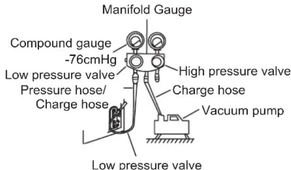
-
Close the Low Pressure side of the manifold gauge, and turn off the vacuum pump.
-
Wait for 5 minutes, then check that there has been no change in system pressure.
- If there is a change in system pressure, refer to Gas Leak Check section for information on how to check for leaks. If there is no change in system pressure, unscrew the cap from the packed valve (high pressure valve).
- Insert hexagonal wrench into the packed valve (high pressure valve) and open the valve by turning the wrench in a 1/4 counterclockwise turn. Listen for gas to exit the system, then close the valve after 5 seconds.
- Watch the Pressure Gauge for one minute to make sure that there is no change in pressure. The Pressure Gauge should read slightly higher than atmospheric pressure.
- Remove the charge hose from the service port.
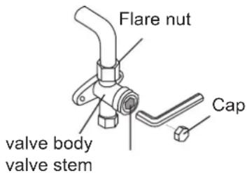
- Using hexagonal wrench, fully open both the high pressure and low pressure valves.
- Tighten valve caps on all three valves (service port, high pressure, low pressure) by hand. You may tighten it further using a torque wrench if needed.
OPEN VALVE STEMS GENTLY
When opening valve stems, turn the hexagonal wrench until it hits against the stopper. Do not try to force the valve to open further.
Note on Adding Refrigerant
Some systems require additional charging depending on pipe lengths. The standard pipe length is 5m (16'). The refrigerant should be charged from the service port on the outdoor unit's low pressure valve. The additional refrigerant to be charged can be calculated using the following formula:
ADDITIONAL REFRIGERANT PER PIPE LENGTH
| Connective Pipe Length (m) | Air Purging Method | Additional Refrigerant | |
| ≤ Standard pipe length | Vacuum Pump | N/A | |
| > Standard pipe length | Vacuum Pump | Liquid Side: ø6.35 (ø0.25")R32:(Pipe length – standard length) × 12g/m(Pipe length – standard length) × 0.13oZ/ft | Liquid Side: ø9.52 (ø0.375")R32:(Pipe length – standard length) × 24g/m(Pipe length – standard length) × 0.26oZ/ft |

CAUTION DO NOT mix refrigerant types.
Precautions on adding the R-32 refrigerant
In addition to the conventional charging procedure, the following requirements shall be kept.
- Make sure that contamination by other refrigerants does not occur for charging.
- To minimize the amount of refrigerant, keep the hoses and lines as short as possible.
- The cylinders shall be kept upright.
- Make sure that the refrigeration system is earthed before charging.
- Label the system after charging, if necessary.
- Extreme care is required not to overcharge the system.
- Before recharging, the pressure shall be checked with nitrogen blowing.
- After charging, check for leakage before commissioning.
- Be sure to check for leakage before leaving the work area.
Important information: regulation regarding the refrigerant used
This product contains fluorinated greenhouse gases. Do not vent gases into the atmosphere.

CAUTION
Inform user if the system contains 5 tCO _2 e or more of fluorinated greenhouse gases. In this case, it must be checked for leakage at least once every 12 months, according to regulation No. 517/2014. This activity must be covered by qualified personnel only. In the case of the situation above, the installer (or authorized person with responsibility for final check) must provide a maintenance book, with all the information recorded, according to REGULATION (EU) No. 517/2014 OF THE EUROPEAN PARLIAMENT AND OF THE COUNCIL of 16 April 2014 on fluorinated greenhouse gases.
1 Please fill in the following with indelible ink on the refrigerant charge label supplied with this product and on this manual.
① the factory refrigerant charge of the product,
② the additional refrigerant amount charged in the field and
1+2 the total refrigerant charge. on the refrigerant charge label supplied with the
product.
| Refrigerant type | GWP value |
| R-32 | 675 |
| GWP: Global Warming PotentialCalculating tCO2e: kg x GWP/1000 | |
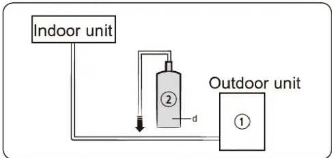
flowchart
graph TD
    A["Indoor unit"] --> B["2"]
    B --> C["Outdoor unit"]
    B --> D["d"]
    D --> B
| Unit | Kg | tCO2e |
| 1,a | ||
| 2,b | ||
| 1+2,c |
NOTE
a Factory refrigerant charge of the product: see unit name plate
b Additional refrigerant amount charged in the field (Refer to the above information for the quantity of refrigerant replenishment.)
c Total refrigerant charge
d Refrigerant cylinder and manifold for charging

CAUTION
- The filled-out label must be adhered in the proximity of the product charging port (e.g. onto the inside of the stop valve cover).
- Make sure that the total refrigerant charge does not exceed (A), the maximum refrigerant charge, which is calculated in the following formula: Maximum refrigerant charge (A)= factory refrigerant charge (B) + maximum additional refrigerant charge due to piping extension (C)
- Here below, the summary table with refrigerant charge limits for each products.
| Model | R32(Unit: G) |
| AR09TXHQASINEUAR09TXHQBWKNEU | 550 |
| AR12TXHQASINEUAR12TXHQBWKNEU | 550 |
| AR18TXHQASINEUAR18TXHQBWKNEU | 1000 |
| AR24TXHQASINEUAR24TXHQBWKNEU | 1600 |
Information about refrigerant
Important information: regulation regarding the refrigerant used.
This product contains fluorinated greenhouse gases. Do not vent gases into the atmosphere.

CAUTION
If the system contains 5 tCO _2 e or more of fluorinated greenhouse gases, it must be checked for leakage at least once every 12 months, according to regulation No. 517/2014. This activity must be covered by qualified personnel only. In the case of the situation above, the installer (or authorized person with responsibility for final check) must provide a maintenance book, with all the information recorded, according to REGULATION (EU) No. 517/2014 OF THE EUROPEAN PARLIAMENT AND OF THE COUNCIL of 16 April 2014 on fluorinated greenhouse gases.
| Refrigerant type | GWP value |
| R-32 | 675 |
• GWP: Global Warming Potential
• Calculating tCO _2 e: kg x GWP/1000
Electrical and Gas Leak Checks
Before Test Run
Only perform test run after you have completed the following steps:
- Electrical Safety Checks – Confirm that the unit's electrical system is safe and operating properly
- Gas Leak Checks – Check all flare nut connections and confirm that the system is not leaking
- Confirm that gas and liquid (high and low pressure) valves are fully open
Electrical Safety Checks
After installation, confirm that all electrical wiring is installed in accordance with local and national regulations, and according to the Installation Manual.
BEFORE TEST RUN
Check Grounding Work
Measure grounding resistance by visual detection and with grounding resistance tester. Grounding resistance must be less than 0.1 .
Note: This may not be required for some locations in the US.
DURING TEST RUN
Check for Electrical Leakage
During the Test Run, use an electroprobe and multimeter to perform a comprehensive electrical leakage test.
If electrical leakage is detected, turn off the unit immediately and call a licensed electrician to find and resolve the cause of the leakage.
Note: This may not be required for some locations in the US.

WARNING – RISK OF ELECTRIC SHOCK
ALL WIRING MUST COMPLY WITH LOCAL AND NATIONAL ELECTRICAL CODES, AND MUST BE INSTALLED BY A LICENSED ELECTRICIAN.
Gas Leak Checks
There are two different methods to check for gas leaks.
Soap and Water Method
Using a soft brush, apply soapy water or liquid detergent to all pipe connection points on the indoor unit and outdoor unit. The presence of bubbles indicates a leak.
Leak Detector Method
f using leak detector, refer to the device's operation manual for proper usage instructions.
AFTER PERFORMING GAS LEAK CHECKS
After confirming that the all pipe connection points DO NOT leak, replace the valve cover on the outside unit.
Check-point of indoor unit
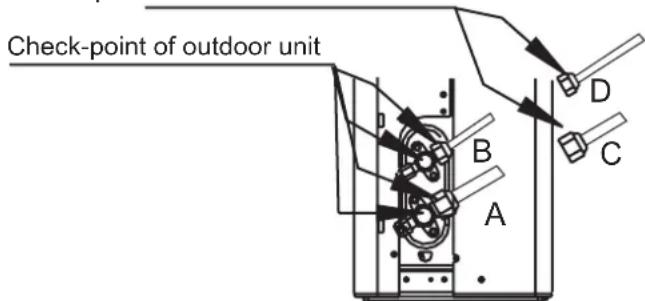
A: Low pressure stop valve
B: High pressure stop valve
C& D: Indoor unit flare nuts
Test Run
Test Run Instructions
You should perform the Test Run for at least 30 minutes.
- Connect power to the unit.
- Press the ON/OFF button on the remote controller to turn it on.
- Press the MODE button to scroll through the following functions, one at a time:
- COOL – Select lowest possible temperature
-
HEAT – Select highest possible temperature
-
Let each function run for 5 minutes, and perform the following checks:
| List of Checks to Perform | PASS/FAIL | |
| No electrical leakage | ||
| Unit is properly grounded | ||
| All electrical terminals properly covered | ||
| Indoor and outdoor units are solidly installed | ||
| All pipe connection points do not leak | Outdoor (2): | Indoor (2): |
| Water drains properly from drain hose | ||
| All piping is properly insulated | ||
| Unit performs COOL function properly | ||
| Unit performs HEAT function properly | ||
| Indoor unit louvers rotate properly | ||
| Indoor unit responds to remote controller | ||
DOUBLE-CHECK PIPE CONNECTIONS
During operation, the pressure of the refrigerant circuit will increase. This may reveal leaks that were not present during your initial leak check. Take time during the Test Run to double-check that all refrigerant pipe connection points do not have leaks. Refer to Gas Leak Check section for instructions.
- After the Test Run is successfully completed, and you confirm that all checks points in List of Checks to Perform have PASSED, do the following:
a. Using remote control, return unit to normal operating temperature.
b. Using insulation tape, wrap the indoor refrigerant pipe connections that you left uncovered during the indoor unit installation process.
IF AMBIENT TEMPERATURE IS BELOW 17°C (62°F)
You can't use the remote controller to turn on the COOL function when the ambient temperature is below 17°C. In this instance, you can use the MANUAL CONTROL button to test the COOL function.
- Lift the front panel of the indoor unit, and raise it until it clicks in place.
-
The MANUAL CONTROL button is located on the right-hand side of the unit. Press it 2 times to select the COOL function.
-
Perform Test Run as normal.
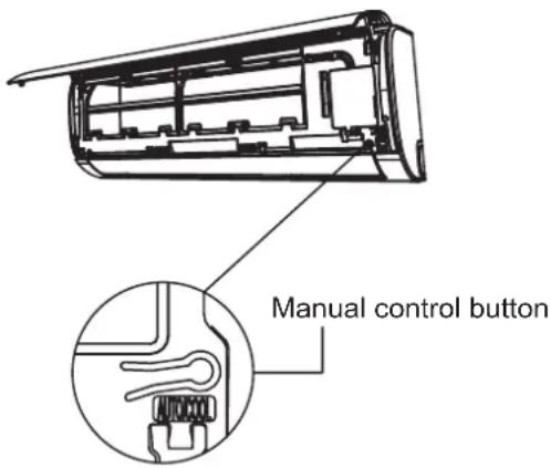
Impedance Information
(Applicable to the following units only))
This appliance MSAFB-12HRN1-QC6 can be connected only to a supply with system impedance no more than 0.373Ω. In case necessary, please consult your supply authority for system impedance information.
This appliance MSAFD-17HRN1-QC5 can be connected only to a supply with system impedance no more than 0.210Ω. In case necessary, please consult your supply authority for system impedance information.
This appliance MSAFD-22HRN1-QC6 can be connected only to a supply with system impedance no more than 0.129Ω. In case necessary, please consult your supply authority for system impedance information.
AIR CONDITIONER
Thank you very much for purchasing our air conditioner. Please read this owner's manual carefully before using your air conditioner. Make sure to save this manual for future reference.
CONTENTS
Remote controller Specifications.... 44
Operation buttons....45
Indicators on LCD 48
How to use the buttons 49
Auto operation 49
Cooling/Heating/Fan operation.... 49
Dehumidifying operation....50
Timer operation....51
Handling the remote controller....55
Remote Controller Specifications
| Model | RG57B1/BGE |
| Rated Voltage 3.0V (Dry batteries R03/LR03×2) | |
| Signal Receiving Range | 8m |
| Environment -5°C~60°C | |
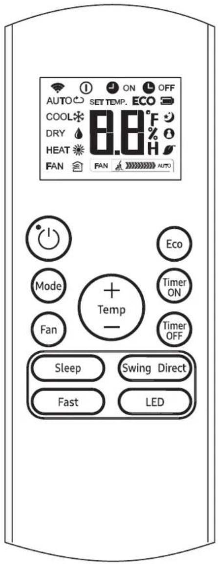
RG57B1/BGE
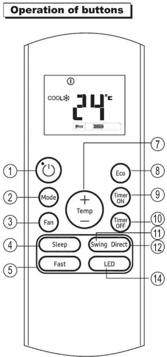
RG57B1/BGE
① ON/OFF Button
This button turns the air conditioner ON and OFF.
② MODE Button
Press this button to modify the air conditioner mode in a sequence of following:

flowchart
graph LR
    A["AUTO COOL"] --> B["DRY FAN HEAT"]
    B --> C[" "]
NOTE: Please do not select HEAT mode if the machine you purchased is cooling only type. Heat mode is not supported by the cooling only appliance.
3 FAN Button
Used to select the fan speed in four steps:

NOTE: You can not switch the fan speed in AUTO or DRY mode.
4 SLEEP Button
- Active/Disable sleep function. It can maintain the most comfortable temperature and save energy. This function is available on COOL, HEAT or AUTO mode only.
- For the detail, see "sleep operation" in "USER'S MANUAL".
NOTE: While the unit is running under SLEEP mode, it would be cancelled if MODE, FAN SPEED or ON/OFF button is pressed.
⑤ TURBO Button
Active/Disable Turbo function. Turbo function enables the unit to reach the preset temperature at cooling or heating operation in the shortest time (if the indoor unit does not support this function, there is no corresponding operation happened when pressing this button.)
6 SELF CLEAN Button
(applicable to RG57A7/BGEF)
Active/Disable Self Clean function
Operation of buttons
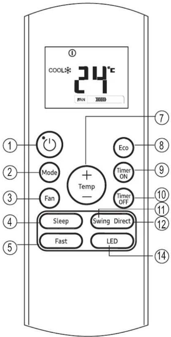
RG57B1/BGE
⑦ UP Button (
Push this button to increase the indoor temperature setting in 1°C increments to 30°C.
DOWN Button ( ▼)
Push this button to decrease the indoor temperature setting in 1°C increments to 17°C.
NOTE: Temperature control is not available in Fan mode.
⑧ ECO Button
Used to enter the energy efficient mode. Under cooling mode, press this button, the remote controller will adjust the temperature automatically to 24^ C, fan speed of Auto to save energy (but only if the set temperature is less than 24^ C). If the set temperature is between 24^ C and 30^ C, press the ECO button, the fan speed will change to Auto, the set temperature will remain unchanged.
NOTE:
- Pressing the TURBO and SLEEP button, modifying the mode or adjusting the set temperature to less than 24^ will stop ECO operation.
- Under ECO operation, the set temperature should be 24°C or more. it may result in insufficient cooling. If you feel uncomfortable, just press the ECO button again to stop it.
9 TIMER ON Button
Press this button to initiate the auto-on time sequence. Each press will increase the auto-timed setting in 30 minutes increments. When the setting time displays 10.0, each press will increase the autotimed setting 60 minutes increments. To cancel the auto-timed program, simply adjust the auto-on time to 0.0.
10 TIMER OFF Button
Press this button to initiate the auto-off time sequence. Each press will increase the auto-timed setting in 30 minutes increments. When the setting time displays 10.0, each press will increase the auto-timed setting 60 minutes increments. To cancel the autotimed program, simply adjust the auto-off time to 0.0
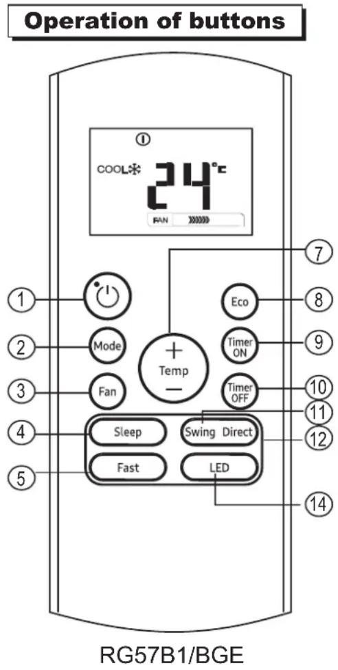
11 SWING Button
Used to stop or start horizontal louver auto swing feature.
12 DIRECT Button
Used to change the louver movement and set the desired up/down air flow direction. The louver changes 6^ in angle for each press.
13 FOLLOW ME Button
(applicable to RG57A7/BGEF) Push this button to initiate the Follow Me feature, the remote display is actual temperature at its location. The remote control will send this signal to the air conditioner every 3 minutes interval until press the Follow Me button again. The air conditioner will cancel the Follow Me feature automatically if it does not receive the signal during any 7 minutes interval.
14 LED Button
Disable/Active indoor screen Display. When pushing the button, the indoor screen display is cleared, press it again to light the display.
NOTE:
- Buttons design is based on typical model and might be slightly different from the actual one you purchased, the actual shape shall prevail.
- All the functions described are accomplished by the unit. If the unit has no this feature, there is no corresponding operation happened when press the relative button on the remote controller.
- When there are wide differences between "Remote controller Illustration" and "USER'S MANUAL" on function description, the description of "USER'S MANUAL" shall prevail.
Indicators on LCD
Information are displayed when the remote controller is powered up.
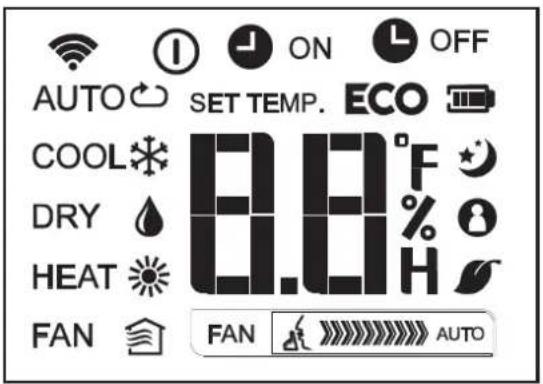
Mode display
AUTO COOL DRY
HEAT PAN


Displayed when data transmitted.

Displayed when remote controller is ON.

Battery display (low battery detection).
ECO
Displayed when ECO feature is activated.

ON Displayed when TIMER ON time is set.

OFF Displayed when TIMER OFF time is set.

Shows set temperature or room temperature, or time under TIMER setting.

Displayed in Sleep Mode operation.

Indicated that the air conditioner is operating in Follow me mode.

Not available for this unit.

Not available for this unit.
Fan speed indication
FAN

Low speed
FAN

Medium speed
FAN
High speed
FAN
AUTO
Auto fan speed
Note:
All indicators shown in the figure are for the purpose of clear presentation. But during the actual operation only the relative functional signs are shown on the display window.
How to use the buttons
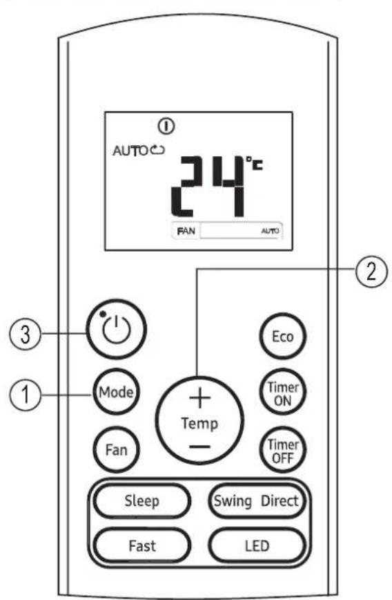
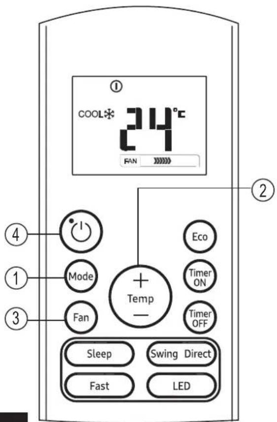
Auto operation
Ensure the unit is plugged in and power is available.
-
Press the MODE button to select Auto.
-
Press the UP/DOWN button to set the desired temperature. The temperature can be set within a range of 17^ C\~ 30^ C in 1^ C increments.
-
Press the ON/OFF button to start the air conditioner.
NOTE
-
In the Auto mode, the air conditioner can logically choose the mode of Cooling, Fan, and Heating by sensing the difference between the actual ambient room temperature and the setting temperature on the remote controller.
-
In the Auto mode, you can not switch the fan speed. It has already been automatically controlled.
-
If the Auto mode is not comfortable for you, the desired mode can be selected manually.
Cooling /Heating/Fan operation
Ensure the unit is plugged in and power is available.
-
Press the MODE button to select COOL, HEAT (cooling & heating models only) or FAN mode.
-
Press the UP/DOWN buttons to set the desired temperature. The temperature can be set within a range of 17°C\~30°C in 1°C increments.
-
Press the FAN button to select the fan speed in four steps- Auto, Low, Med, or High.
-
Press the ON/OFF button to start the air conditioner.
NOTE
In the FAN mode, the setting temperature is not displayed in the remote controller and you are not able to control the room temperature either. In this case, only step 1, 3 and 4 may be performed.
How to use the buttons
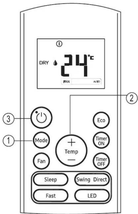
Dehumidifying operation
Ensure the unit is plugged in and power is available.
-
Press the MODE button to select DRY mode.
-
Press the UP/DOWN buttons to set the desired temperature. The temperature can be set within a range of 17^ C\~ 30^ C in 1^ C increments.
-
Press the ON/OFF button to start the air conditioner.
NOTE
In the Dehumidifying mode, you can not switch the fan speed. It has already been automatically controlled.
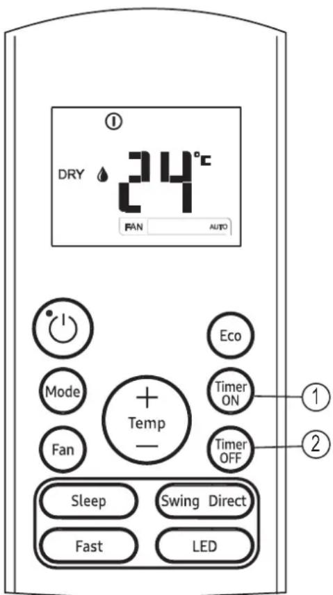
Timer operation
Press the TIMER ON button can set the auto-on time of the unit. Press the TIMER OFF button can set the auto-off time of the unit.
To set the Auto-on time.
- Press the TIMER ON button. The remote controller shows TIMER ON, the last Auto-on setting time and the signal "H" will be shown on the LCD display area. Now it is ready to reset the Auto-on time to START the operation.
- Push the TIMER ON button again to set desired Auto-on time. Each time you press the button, the time increases by half an hour between 0 and 10 hours and by one hour between 10 and 24 hours.
- After setting the TIMER ON, there will be a one second delay before the remote controller transmits the signal to the air conditioner. Then, after approximately another 2 seconds, the signal "h" will disappear and the set temperature will re-appear on the LCD display window.
To set the Auto-off time.
- Press the TIMER OFF button. The remote controller shows TIMER OFF, the last Auto-off setting time and the signal "H" will be shown on the LCD display area. Now it is ready to reset the Auto-off time to stop the operation.
- Push the TIMER OFF button again to set desired Auto-off time. Each time you press the button, the time increases by half an hour between 0 and 10 hours and by one hour between 10 and 24 hours.
- After setting the TIMER OFF, there will be a one second delay before the remote controller transmits the signal to the air conditioner. Then, after approximately another 2 seconds, the signal "H" will disappear and the set temperature will re-appear on the LCD display window.
CAUTION
- The effective operation time set by the remote controller for the timer function is limited to the following settings: 0.5, 1.0, 1.5, 2.0, 2.5, 3.0, 3.5, 4.0, 4.5, 5.0, 5.5, 6.0, 6.5, 7.0, 7.5, 8.0, 8.5, 9.0, 9.5, 10, 11, 12, 13, 14, 15, 16, 17, 18, 19, 20, 21, 22, 23 and 24.
Example of timer setting
Set 6 hours later
TIMER ON
(Auto-on Operation)
The TIMER ON feature is useful when you want the unit to turn on automatically before you return home. The air conditioner will automatically start operating at the set time.
Example:
To start the air conditioner in 6 hours.
- Press the TIMER ON button, the last setting of starting operation time and the signal "H" will show on the display area.
- Press the TIMER ON button to display "6.0H" on the TIMER ON display of the remote controller.
- Wait for 3 seconds and the digital display area will show the temperature again. The "TIMER ON" indicator remains on and this function is activated.
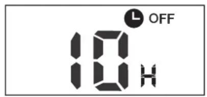
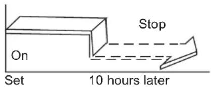
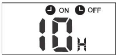
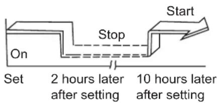
TIMER OFF
(Auto-off Operation)
The TIMER OFF feature is useful when you want the unit to turn off automatically after you go to bed. The air conditioner will stop automatically at the set time.
Example:
To stop the air conditioner in 10 hours.
- Press the TIMER OFF button, the last setting of stopping operation time and the signal "H" will show on the display area.
- Press the TIMER OFF button to display "10H" on the TIMER OFF display of the remote controller.
- Wait for 3 seconds and the digital display area will show the temperature again. The "TIMER OFF" indicator remains on and this function is activated.
COMBINED TIMER
(Setting both ON and OFF timers simultaneously)
(On → Stop → Start operation)
This feature is useful when you want to stop the air conditioner after you go to bed, and start it again in the morning when you wake up or when you return home.
Example:
To stop the air conditioner 2 hours after setting and start it again 10 hours after setting.
- Press the TIMER OFF button.
- Press the TIMER OFF button again to display 2.0H on the TIMER OFF display.
- Press the TIMER ON button.
- Press the TIMER ON button again to display 10H on the TIMER ON display.
- Wait for 3 seconds and the digital display area will show the temperature again. The "TIMER ON OFF" indicator remains on and this function is activated.
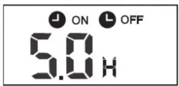
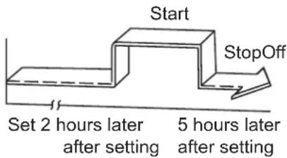
(Off → Start → Stop operation)
This feature is useful when you want to start the air conditioner before you wake up and stop it after you leave the house.
Example:
To start the air conditioner 2 hours after setting, and stop it 5 hours after setting.
- Press the TIMER ON button.
- Press the TIMER ON button again to display 2.0H on the TIMER ON display.
- Press the TIMER OFF button.
- Press the TIMER OFF button again to display 5.0H on the TIMER OFF display.
- Wait for 3 seconds and the digital display area will show the temperature again.
The "TIMER ON & TIMER OFF" indicator remains on and this function is activated.
The device could comply with the local national regulations.
- In Canada, it should comply with CAN ICES-3 (B)/NMB-3 (B).
- In USA, this device complies with part 15 of the FCC Rules. Operation is subject to the following two conditions:
(1) this device may not cause harmful interference, and
(2) this device must accept any interference received, including interference that may cause undesired operation.
Changes or modifications not approved by the party responsible for compliance could void user's authority to operate the equipment.
NOTE:
This equipment has been tested and found to comply with the limits for a Class B digital device, pursuant to part 15 of the FCC Rules. These limits are designed to provide reasonable protection against harmful interference in a residential installation. This equipment generates, uses and can radiate radio frequency energy and, if not installed and used in accordance with the instructions, may cause harmful interference to radio communications. However, there is no guarantee that interference will not occur in a particular installation. If this equipment does cause harmful interference to radio or television reception, which can be determined by turning the equipment off and on, the user is encouraged to try to correct the interference by one or more of the following measures:
- Reorient or relocate the receiving antenna.
- Increase the separation between the equipment and receiver.
- Connect the equipment into an outlet on a circuit different from that to which the receiver is connected.
- Consult the dealer or an experienced radio/TV technician for help.
Handling the remote controller
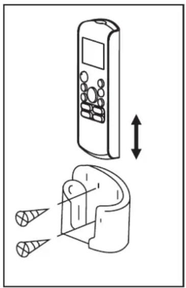
natural_image
Diagram showing a remote control device with an arrow indicating vertical displacement, and a close-up of its internal components (no text or symbols present)Location of the remote controller.
- Use the remote controller within a distance of 8 meters from the appliance, pointing it towards the receiver. Reception is confirmed by a beep.
CAUTIONS
- The air conditioner will not operate if curtains, doors or other materials block the signals from the remote controller to the indoor unit.
- Prevent any liquid from falling into the remote controller. Do not expose the remote controller to direct sunlight or heat.
- If the infrared signal receiver on the indoor unit is exposed to direct sunlight, the air conditioner may not function properly. Use curtains to prevent the sunlight from falling on the receiver.
- If other electrical appliances react to the remote controller, either move these appliances or consult your local dealer.
- Do not drop the remote controller. Handle with care.
- Do not place heavy objects on the remote controller, or step on it.
Using the remote controller holder (optional)
- The remote controller can be attached to a wall or pillar by using a remote controller holder (not supplied, purchased separately).
- Before installing the remote controller, check that the air conditioner receives the signals properly.
• Install the remote controller with two screws. - For installing or removing the remote controller, move it up or down in the holder.
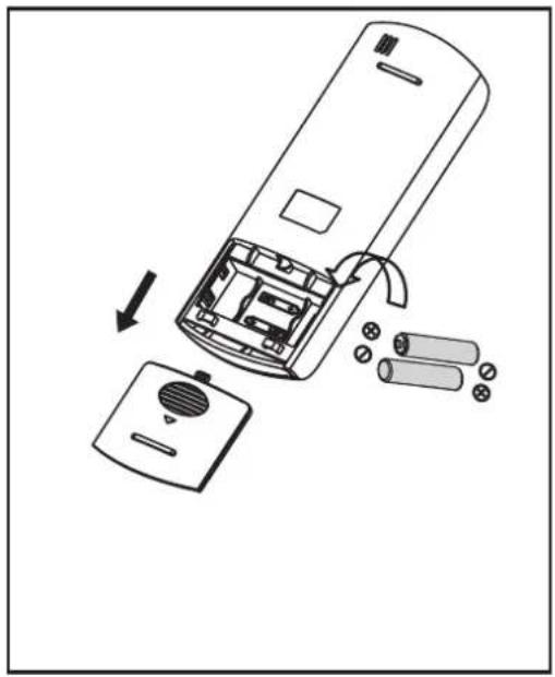
natural_image
Diagram of a remote control casing with internal components and battery pack (no text or symbols)Replacing batteries
The following cases signify exhausted batteries. Replace old batteries with new ones.
- Receiving beep is not emitted when a signal is transmitted.
- Indicator fades away.
The remote controller is powered by two dry batteries (R03/LR03×2) housed in the back rear part and protected by a cover.
(1) Remove the cover in the rear part of the remote controller.
(2) Remove the old batteries and insert the new batteries, placing the (+) and (-) ends correctly.
(3) Install the cover back on.
NOTE: When the batteries are removed, the remote controller erases all programming. After inserting new batteries, the remote controller must be reprogrammed.
CAUTIONS
- Do not mix old and new batteries or batteries of different types.
- Do not leave the batteries in the remote controller if they are not going to be used for 2 or 3 months.
- Do not dispose batteries as unsorted municipal waste. Collection of such waste separately for special treatment is necessary.
Performing the gas leak tests for repair
In case of repair of the refrigerant circuit, the following procedure must be kept to consider flammability.
1 Remove the refrigerant.
2 Purge the refrigerant circuit with inert gas.
3 Perform evacuation.
4 Purge the circuit again with inert gas.
5 Open the circuit.
6 Perform repair work.
7 Charge the system with refrigerant.
8 Flush the system with nitrogen blowing for safety.
9 Repeat the previous steps several times until no refrigerant is within the system.

CAUTION
- Compressed air or oxygen shall not be used.
- Flush the system with nitrogen blowing, fill the refrigerant until the working pressure is reached, ventilate to atmosphere, and then pull down to a vacuum state.
- For the final nitrogen blowing charge, the system shall be ventilated down to atmospheric pressure.
- The procedure is absolutely vital in case of brazing on the pipings.
- Make sure that the outlet of the vacuum pump is not closed to any ignition sources and there is ventilation available.
- Do not apply any permanent inductive or capacitance loads to the circuit without ensuring that this will not exceed the permissible voltage and current permitted for the air conditioner.
Decommissioning
The following requirements must be fulfilled before and while taking the decommissioning procedure:
- Before decommissioning, the worker shall be familiar with the product details.
- The entire refrigerant shall be recovered safely.
- Before starting the process, oil and
refrigerant samples shall be taken just in case analysis is required for reuse.
- Before starting the process, power supply must be available.
1 Be familiar with the equipment details.
2 Isolate the system electrically.
3 Before starting the process, make sure that:
- Any mechanical equipment is available for handling refrigerant cylinders.
- All PPE (personal protective equipment) is available for servicing.
- The recovery process shall be supervised by a competent person.
- The recovery equipment and cylinders comply with the standards.
4 Lower the refrigeration system, if possible.
5 If vacuuming is not possible, make a manifold so that refrigerant can be easily removed from the parts of the system.
6 Make sure that the cylinders are placed on the scales before recovery.
7 Run the recovery system in accordance with the manufacturer's instructions.
8 Do not overcharge the cylinders. (No more than 80 %)
9 Be sure to keep the cylinder within the maximum working pressure, even temporarily.
10 After charging, make sure that the cylinders and the equipment are promptly removed from the site and all isolation valves are closed.
11 Recovered refrigerant shall not be charged into other refrigeration system unless it is cleaned and checked.
For information on Samsung's environmental commitments and product-specific regulatory obligations, e.g. REACH, WEEE, Batteries, visit : samsung.com/uk/aboutsamsung/samsungelectronics/corporatecitizenship/data_corner.html


This appliance is filled with R-32.
Condizionatore
natural_image
Hand placing a black arrow on a patterned panel inside a vehicle (no text or symbols visible)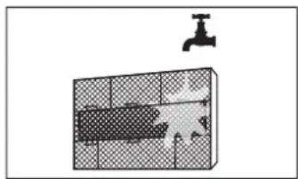
natural_image
Diagram of a bathroom sink with a faucet and tiled wall (no text or symbols)
ATTENZIONE
natural_image
Simple 3D grid diagram with a small arrow pointing to the top-right corner (no text or symbols)natural_image
Simple line drawing of a house with wavy lines inside, no text or symbols presentnatural_image
Line drawing of a device with internal components (no text or symbols)natural_image
Cross-sectional diagram of a hazard symbol with lightning bolts indicating electrical hazard (no text or labels)natural_image
Diagram of a 3D grid structure with a labeled angle 'P' (no text or symbols beyond the label)natural_image
Simple diagram showing a crossed-out circle with a diagonal line and two droplet symbols inside, no text or labels present.natural_image
Line drawing of a device with internal components (no text or symbols)natural_image
Illustration of a hand using a tool to adjust a component, with no visible text or symbols.natural_image
Mechanical diagram showing a tool interacting with a bolt and nut (no text or symbols present)natural_image
Illustration of hands holding a black object over a textured surface, no text or symbols presentnatural_image
Diagram of a cable being inserted into a wire, showing layered structure and cable ends (no text or symbols)natural_image
Illustration of two hands holding a horizontal bar with three upward arrows, no text or symbols presentnatural_image
Technical line drawing of a rectangular electronic component or enclosure with internal compartments and mounting holes (no text or symbols)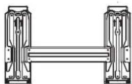
natural_image
Pure mechanical assembly diagram showing two vertical components connected by a horizontal bar (no text or symbols)Tipo B
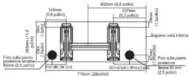
Modello A
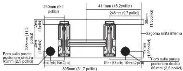
Modello B
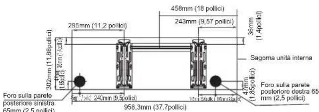
Modello C
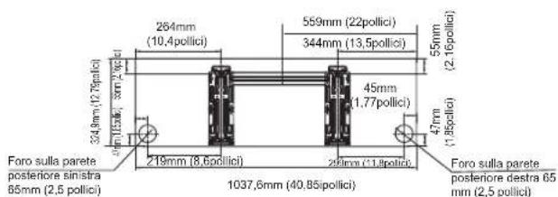
Modello D
natural_image
Technical line drawing of two mechanical components with spring-loaded ends (no text or symbols)
ATTENZIONE
natural_image
Simple line drawing of a mechanical joint or bracket with a checkmark (no text or symbols)CORRETTO
natural_image
Simple line drawing of a mechanical joint or bracket with a cross symbol (no text or labels)NON CORRETTO
natural_image
Simple line drawing of a pipe connection with a wall and ground, no text or symbols presentNON CORRETTO
natural_image
Simple line drawing of a toilet with a wall and pipe, no text or symbols presentNON CORRETTO
natural_image
Technical line drawing of a front-end air conditioner unit with labeled dimensions H and W (no text or symbols beyond labels)| Dimensioni unità esterna (mm)W × H × D | Dimensioni di montaggio | |
| Distanza A (mm) | Distanza B (mm) | |
| 720 × 495 × 270 (28,3" × 19,5" × 10,6") 452 | (17,7") 255 (10,0") | |
| 800 × 554 × 333 (31,5" × 21,8" × 13,1") 514 | (20,2") 340 (13,4") | |
| 845 × 702 × 363 (33,3" × 27,6" × 14,3") 540 | (21,3") 350 (13,8") | |
Nel Nord America
natural_image
Illustration of a mechanical lever assembly with three plates and a handle (no text or symbols)natural_image
Illustration of hands using a tool to lift a mechanical component (no text or symbols)REQUISITI DI COPPIA
| Diametro esterno del tubo (mm) | Coppia di serraggio (N • m) | Dimensione del chiarore (B) (mm) | Forma svasata |
| 6,35 ( 0,25") | 18~20 (180~200kgf.cm) 8 | 4~8,7 (0,33~0,34") | 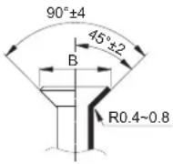 |
| 9,52 ( 0,375") | 32~39 (320~390kgf.cm) 1 | 3,2~13,5 (0,52~0,53") | |
| 12,7 ( 0,5") | 49~59 (490~590kgf.cm) 1 | 6,2~16,5 (0,64~0,65") | |
| 15,88 ( 0,63") | 57~71 (570~710kgf.cm) 1 | 9,2~19,7 (0,76~0,78") |
NON USARE COPPIE ECESSIVE
natural_image
Line drawing of hands using a tool to adjust or install a mechanical component (no text or symbols present)6 Tasto SELF CLEAN (AUTOPULENTE) (applicabile a RG57A7/BGEF
13 Tasto FOLLOW ME (SEGUI ME) (applicabile a RG57A7/BGEF)
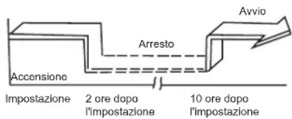
natural_image
Diagram showing a remote control device with two spools and a directional arrow indicating movement (no text or symbols present)natural_image
Diagram of a remote control casing with internal components and battery pack (no text or symbols)natural_image
Line drawing of a hand opening a car air vent with a black arrow indicating the down-left direction (no text or symbols)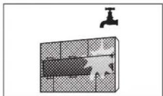
natural_image
Diagram showing a faucet above a grid-patterned room with a pipe running through (no text or symbols)natural_image
3D grid diagram with shaded cells and an angle label 'F' (no text or symbols beyond the label)natural_image
Simple line drawing of a house with wavy lines inside, no text or symbols presentnatural_image
Line drawing of a smartphone with internal components (no text or symbols)natural_image
Diagram of a 3D grid structure with a labeled dimension 'H' (no text or symbols beyond the label)natural_image
Prohibition sign with diagonal line crossing a shaded rectangle, no text or symbols presentnatural_image
Line drawing of a mechanical device with internal components (no text or symbols)natural_image
Illustration of a hand using a tool to adjust a component, with no visible text or symbols.Fúrjon lyukat a falba
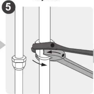
natural_image
Illustration of hands holding a black object over a textured surface, no text or symbols presentnatural_image
Diagram of a cable being inserted into a wire, showing layered structure and cable arrangement (no text or symbols)natural_image
Illustration of two hands holding a rectangular object with horizontal lines and upward arrows, no text or symbols presentnatural_image
Technical line drawing of a rectangular electronic component with internal slots and mounting holes (no text or symbols)natural_image
Pure mechanical assembly diagram showing two vertical components connected by a horizontal bar (no text or symbols)B típus
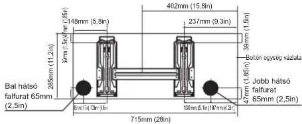
A modell
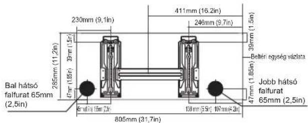
B modell
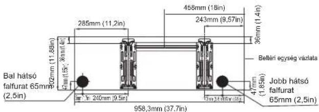
C modell
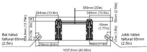
D modell
natural_image
Technical line drawing of two mechanical components with spring-loaded ends (no text or symbols)
VIGYÁZAT
natural_image
Pure mechanical diagram showing a bracket and checkmark symbol without any text or labelsTERMÉK
natural_image
Pure mechanical diagram showing a bracket and vertical wall with a cross symbol (no text or labels)HELYTELEN
natural_image
Pure diagram of a pipe connection with a wall and ground, no text or symbols presentHELYTELEN
natural_image
Simple line drawing of a toilet or sink with a wall and pipe, no text or symbols presentHELYTELEN
natural_image
Pure technical diagram showing a curved grid structure above a rectangular plate with supports (no text or symbols)natural_image
Technical line drawing of a front-end air conditioner unit with labeled dimensions H and W (no text or symbols beyond labels)natural_image
Illustration of a mechanical clamp or lever assembly with multiple base plates (no text or symbols)A CSŐ TÚLNYÚLIK A PRÉSIDOMON
| A cső külső átmérője (mm) | A (mm) | |
| Min. Max. | ||
| 6,35 ( 0,25") 0,7 (0,0275") 1,3 (0,05") | 7 (0,0275") 1,3 | (0,05") |
| 9,52 ( 0,375") 1,0 (0,04") 1,6 (0,063") | 1,0 (0,04") 1,6 | (0,063") |
| 12,7 ( 0,5") 1,0 (0,04") 1,8 (0,07") | 1,0 (0,04") 1,8 | (0,07") |
| 15,88 ( 0,63") 2,0 (0,078") 2,2 (0,086") | 2,0 (0,078") 2,2 | (0,086") |
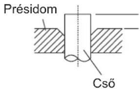
natural_image
Diagram showing two mechanical components with a directional arrow indicating movement or assembly (no text or symbols present)natural_image
Illustration of a hand using a tool to lift a mechanical component (no text or symbols present)NYOMTÉKKÖVETELMÉNYEK
natural_image
Line drawing of hands using a tool to adjust or install a mechanical component (no text or symbols present)Levegőtlenítés
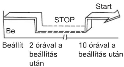
natural_image
Diagram showing a remote control device with an arrow indicating vertical displacement, and a close-up of its internal components (no text or symbols present)natural_image
Diagram of a remote control casing with internal components and battery pack (no text or symbols)Elemek cseréje
natural_image
Diagram showing a hand pressing down on a car air vent with a black arrow indicating the direction (no text or symbols present)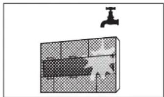
natural_image
Diagram of a bathroom sink with faucet and tiled floor (no text or symbols)
ΠΡΟΣΟΧΗ
natural_image
3D grid diagram with hatched fill and a small arrow pointing to the top-right corner (no text or symbols)natural_image
Simple line drawing of a house with wavy lines inside, enclosed in a rounded square frame (no text or symbols)natural_image
Technical line drawing of a smartphone internal component (no text or symbols)natural_image
Diagram of a 3D grid structure with a labeled angle marker (no text or symbols present)natural_image
Technical line drawing of a mechanical device with internal components (no text or symbols)natural_image
Illustration of hands performing a finger manipulation technique on a textured surface (no text or symbols)natural_image
Diagram of a cable being inserted into a wire, showing layered structure and cable arrangement (no text or symbols)natural_image
Illustration of two hands holding a horizontal bar with upward arrows, no text or symbols present(1) (2)
natural_image
Technical line drawing of a rectangular electronic component with internal compartments and mounting holes (no text or symbols)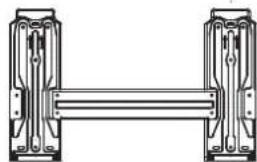
natural_image
Pure mechanical assembly diagram showing two vertical components connected by a horizontal bar (no text or symbols)Τύπος Β
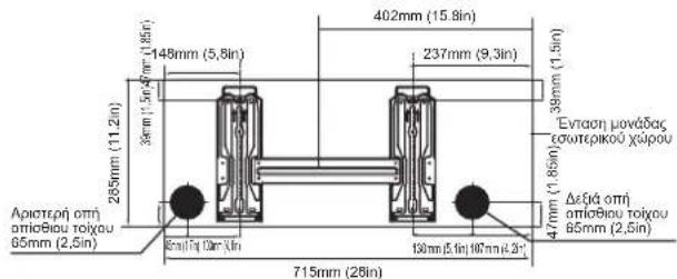
natural_image
Technical line drawing of two mechanical components with spring-loaded arms (no text or symbols)
ΠΡΟΣΟΧΗ
natural_image
Pure mechanical diagram showing a bracket and vertical wall with a checkmark (no text or symbols)ΔΙΓΟΡΘΩΣΗ
natural_image
Simple line drawing of a door and wall joint with a cross symbol (no text or labels)ΛΑΘΟΣ
natural_image
Simple line drawing of a wall-mounted cable or pipe connection with a cross symbol (no text or labels)ΛΑΘΟΣ
natural_image
Simple line drawing of a door latch connected to a wall, with no text or symbols present.ΛΑΘΟΣ
natural_image
Technical line drawing of a front-end air conditioner unit with labeled dimensions H and W (no text or symbols beyond labels)natural_image
Technical line drawing of a mechanical clamp or lever assembly (no text or symbols)natural_image
Illustration of hands using a tool to lift a mechanical component (no text or symbols)ΑΠΑΙΤΗΣΕΙΣ ΡΟΠΗΣ
natural_image
Line drawing of a dual air conditioner unit with fan and vent (no text or symbols)Κάλυμμα βαλβίδας
natural_image
Line drawing of hands using a tool to adjust or install a mechanical component (no text or symbols present)Εκκένωση Αέρα
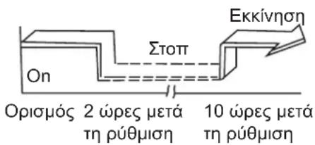
natural_image
Diagram showing a remote control device with two spools and an open lid, no text or symbols presentnatural_image
Diagram of a remote control casing with internal components and battery pack (no text or symbols)- User manual/Installation manual
- Table of Contents
- Safety Precautions....03
- User manual
- Unit Specifications and Features 10
- Care and Maintenance....14
- Troubleshooting....16
- Installation Manual
- Accessories....19
- Installation Summary - Indoor Unit....20
- Unit Parts....21
- Indoor Unit Installation....22
- Outdoor Unit Installation 29
- Refrigerant Piping Connection 33
- Air Evacuation....36
- Electrical and Gas Leak Checks....39
- Test Run 39
- Safety Precautions
- WARNING
- CAUTION
- WARNINGS FOR PRODUCT USE
- CLEANING AND MAINTENANCE WARNINGS
- ELECTRICAL WARNINGS
- TAKE NOTE OF FUSE SPECIFICATIONS
- WARNINGS FOR PRODUCT INSTALLATION
- Installation of the outdoor unit
- Note about Fluorinated Gasses (Not applicable to the unit using Refrigerant)
- WARNING for Using R32 Refrigerant
- Preparation of fire extinguisher
- Ignition sources free
- Area ventilation
- Leakage detection methods
- Labelling
- Recovery
- (Applicable in countries with separate collection systems)
- Unit Specifications and Features
- Indoor unit display
- Operating temperature
- FOR OUTDOOR UNITS WITH AUXILIARY ELECTRIC HEATER
- To further optimize the performance of your unit, do the following:
- Other Features
- • Auto-Restart (some units)
- • Anti-mildew (some units)
- - Wireless Control (some units)
- - Louver Angle Memory (some units)
- - Refrigerant Leakage Detection (some units)
- - Sleep Operation
- - Setting Angle of Air Flow
- Setting vertical angle of air ow
- NOTE ON LOUVER ANGLES
- Setting horizontal angle of air flow
- Manual Operation (without remote)
- Care and Maintenance
- Cleaning Your Indoor Unit
- BEFORE CLEANING OR MAINTENANCE
- Cleaning Your Air Filter
- Maintenance – Long Periods of Non-Use
- Maintenance – Pre-Season Inspection
- Troubleshooting
- DO NOT ATTEMPT TO FIX THESE YOURSELF! CONTACT AN AUTHORIZED SERVICE PROVIDER IMMEDIATELY!
- Common Issues
- Accessories
- Installation Summary - Indoor Unit
- Unit Parts
- NOTE ON ILLUSTRATIONS
- Indoor Unit Installation
- Installation Instructions – Indoor unit
- PRIOR TO INSTALLATION
- Step 1: Select installation location
- Proper installation locations meet the following standards:
- DO NOT install unit in the following locations:
- NOTE ABOUT WALL HOLE:
- Refer to the following diagram to ensure proper distance from walls and ceiling:
- Step 2: Attach mounting plate to wall
- NOTE FOR CONCRETE OR BRICK WALLS:
- Step 3: Drill wall hole for connective piping
- MOUNTING PLATE DIMENSIONS
- Step 4: Prepare refrigerant piping
- NOTE ON PIPING ANGLE
- Step 5: Connect drain hose
- NOTE ON DRAIN HOSE PLACEMENT
- PLUG THE UNUSED DRAIN HOLE
- BEFORE PERFORMING ANY ELECTRICAL WORK, READ THESE REGULATIONS
- BEFORE PERFORMING ANY ELECTRICAL OR WIRING WORK, TURN OFF THE MAIN POWER TO THE SYSTEM.
- Step 6: Connect signal cable
- Cable Types
- Minimum Cross-Sectional Area of Power and Signal Cables (For reference)
- CHOOSE THE RIGHT CABLE SIZE
- ALL WIRING MUST BE PERFORMED STRICTLY IN ACCORDANCE WITH THE WIRING DIAGRAM LOCATED ON THE BACK OF THE INDOOR UNIT'S FRONT PANEL.
- DO NOT MIX UP LIVE AND NULL WIRES
- NOTE ABOUT WIRING
- THE WIRING CONNECTION PROCESS MAY DIFFER SLIGHTLY BETWEEN UNITS AND REGIONS.
- Step 7: Wrappiping and cables
- DRAIN HOSE MUST BE ON BOTTOM
- DO NOT INTERTWINE SIGNAL CABLE WITH OTHER WIRES
- DO NOT WRAP ENDS OF PIPING
- Step 8: Mount indoor unit
- If you installed new connective piping to the outdoor unit, do the following:
- If refrigerant piping is already embedded in the wall, do the following:
- UNIT IS ADJUSTABLE
- Outdoor Unit Installation
- Installation Instructions – Outdoor unit
- If the unit is exposed to heavy wind:
- If the unit is frequently exposed to heavy rain or snow:
- If the unit is frequently exposed to salty air (seaside):
- Step 2: Install drain joint (Heat pump unit only)
- If the drain joint comes with a rubber seal (see Fig. A), do the following:
- If the drain joint doesn't come with a rubber seal (see Fig. B), do the following:
- ! IN COLD CLIMATES
- Step 3: Anchor outdoor unit
- UNIT MOUNTING DIMENSIONS
- Step 4: Connect signal and power cables
- USE THE RIGHT CABLE
- PAY ATTENTION TO LIVE WIRE
- ALL WIRING WORK MUST BE PERFORMED STRICTLY IN ACCORDANCE WITH THE WIRING DIAGRAM LOCATED INSIDE OF WIRE COVER OF THE OUTDOOR UNIT.
- In North America
- Refrigerant Piping Connection
- Note on Pipe Length
- Connection Instructions – Refrigerant Piping
- Step 1: Cut pipes
- DO NOT DEFORM PIPE WHILE CUTTING
- Step 2: Remove burrs
- Step 3: Flare pipe ends
- Step 4: Connect pipes
- MINIMUM BEND RADIUS
- Instructions for Connecting Piping to Indoor Unit
- DO NOT USE EXCESSIVE TORQUE
- Instructions for Connecting Piping to Outdoor Unit
- USE SPANNER TO GRIP MAIN BODY OF VALVE
- Air Evacuation
- Preparations and Precautions
- BEFORE PERFORMING EVACUATION
- Evacuation Instructions
- OPEN VALVE STEMS GENTLY
- Note on Adding Refrigerant
- Precautions on adding the R-32 refrigerant
- Important information: regulation regarding the refrigerant used
- NOTE
- Information about refrigerant
- Electrical and Gas Leak Checks
- Before Test Run
- Electrical Safety Checks
- Check Grounding Work
- DURING TEST RUN
- Check for Electrical Leakage
- WARNING – RISK OF ELECTRIC SHOCK
- Gas Leak Checks
- Soap and Water Method
- Leak Detector Method
- AFTER PERFORMING GAS LEAK CHECKS
- Test Run
- Test Run Instructions
- DOUBLE-CHECK PIPE CONNECTIONS
- IF AMBIENT TEMPERATURE IS BELOW 17°C (62°F)
- Impedance Information
- AIR CONDITIONER
- CONTENTS
- ① ON/OFF Button
- ② MODE Button
- FAN Button
- SLEEP Button
- ⑤ TURBO Button
- SELF CLEAN Button
- ⑦ UP Button (
- DOWN Button ( ▼)
- ⑧ ECO Button
- NOTE:
- TIMER ON Button
- TIMER OFF Button
- SWING Button
- DIRECT Button
- FOLLOW ME Button
- LED Button
- Indicators on LCD
- Mode display
- Fan speed indication
- Auto operation
- Cooling /Heating/Fan operation
- Dehumidifying operation
- Timer operation
- To set the Auto-on time.
- To set the Auto-off time.
- Example of timer setting
- TIMER ON
- (Auto-on Operation)
- Example:
- TIMER OFF
- (Auto-off Operation)
- COMBINED TIMER
- Handling the remote controller
- Location of the remote controller.
- CAUTIONS
- Using the remote controller holder (optional)
- Replacing batteries
- Performing the gas leak tests for repair
- Decommissioning
- Condizionatore
- ATTENZIONE
- Nel Nord America
- NON USARE COPPIE ECESSIVE
- Tasto SELF CLEAN (AUTOPULENTE) (applicabile a RG57A7/BGEF
- Tasto FOLLOW ME (SEGUI ME) (applicabile a RG57A7/BGEF)
- VIGYÁZAT
- Levegőtlenítés
- Elemek cseréje
- ΠΡΟΣΟΧΗ
- Εκκένωση Αέρα
Brand : SAMSUNG
Model : AR12TXHQASIN
Category : Air-conditioner