
STA8743U - Food Processor SMEG - Free user manual and instructions
Find the device manual for free STA8743U SMEG in PDF.

| Product type | Multi-function stand mixer |
| Brand | SMEG |
| Model | STA8743U |
| Dimensions (L x W x H) | 40 x 25 x 35 cm |
| Weight | 10 kg |
| Power supply | 220-240 V, 50/60 Hz |
| Rated power | 1000 W |
| Main bowl capacity | 4.5 liters |
| Speeds | 10 speeds + pulse function |
| Main functions | Knead, whip, mix, chop, slice, grate, blend |
| Included accessories | Whisk, paddle, dough hook, blender jar, slicing/shredding discs |
| Materials | Stainless steel bowl, ABS plastic and metal body |
| Care and cleaning | Dishwasher-safe accessories (bowl, whisk, paddle, dough hook) |
| Safety | Automatic shut-off in case of overload, safety bowl lock, anti-start if improperly assembled |
| Spare parts and repairability | Parts available on SMEG website, repairable by authorized center |
| General information | Retro design, cream or pastel color, anti-slip feet, cable storage |
Frequently Asked Questions - STA8743U SMEG
User questions about STA8743U SMEG
0 question about this device. Answer the ones you know or ask your own.
Ask a new question about this device
Download the instructions for your Food Processor in PDF format for free! Find your manual STA8743U - SMEG and take your electronic device back in hand. On this page are published all the documents necessary for the use of your device. STA8743U by SMEG.
USER MANUAL STA8743U SMEG
GUIDE FOR USING THE DISHWASHER AND THE WASHING PROGRAMS
CONTENTS
1 INTRODUCTION 3
2 DESCRIPTION AND USE OF THE CONTROLS 5
2.1 Upper panel 5
2.2 Setting the washing program and switching on and off....6
2.2.1 Switching on 9
2.2.2 Selecting and starting the program....9
2.2.3 End of program....10
2.2.4 Interrupting a program....10
2.2.5 Changing the current program 10
2.2.6 Canceling the current program....11
2.2.7 Options....11
2.2.8 Switching off 13
2.3 Additional features....13
2.3.1 Adjusting the water softener....13
3 ENERGY SAVING AND ENVIRONMENTAL RESPECT 15
3.1 Reducing the consumption of detergent and respecting the environment. 15
4 REMOVING THE DISHES....16
5 TROUBLESHOOTING....17
1 INTRODUCTION
Thank you for choosing one of our products. To use this dishwasher correctly and safely, please read this manual carefully. The manual is divided into sections giving you a step-by-step guide to all your appliance's functions. The texts are easy to understand and are complete with detailed illustrations. This user-friendly manual will provide answers to all your questions about use of the dishwasher.
Before using this dishwasher, carefully read chapter 2 “Use and safety warnings” of the attached general manual.
For any other information about use and maintenance of the dishwasher, read the enclosed general manual carefully.
This manual comprises the following sections:
INTRODUCTION: general information about the manual.
USER INSTRUCTIONS: advice on using the washing programs and information about all the dishwasher functions.
Nomenclature of figures and tables:
The progressive number of each figure is shown in the bottom right-hand corner of the relative box. An example of a progressive number is “Fig. 4-01”, where the first number (4) indicates the section to which the figure belongs, while the second number (01) indicates the progressive number of the figure in section 4 (Fig. 4-01 is the first figure in section 4). The tables are numbered in the same way, bearing in mind that “Tab.” is used instead of “Fig.” (e.g.: Tab. 4-01 is the first table in section 4). If a table occupies more than one page, a letter is added after the progressive number (e.g.: “Tab. 4-01a”, Tab. 4-01b”).
Symbols used in this manual (see tab. 1-01)
 | DANGER. This symbol highlights information and warnings which, if not observed, may compromise personal safety or damage the appliance. |
 | This symbol highlights general information and warnings. |
| Tab. 1-01 | |
2 DESCRIPTION OF THE CONTROLS
2.1 Upper panel
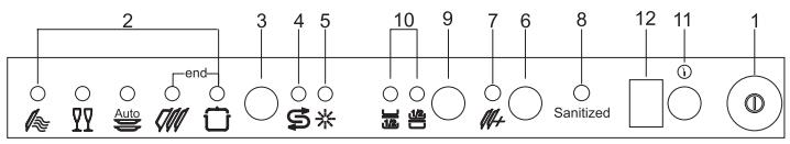
All the dishwasher controls are grouped on the upper panel (see fig. 2-01). The dishwasher can only be switched on, programmed, switched off, etc. with the door open.
A brief description (see tab. 2-01) of the various controls on the upper panel is given below.
text_image
2 3 4 5 10 9 7 6 8 12 11 1 end Auto SanitizedFIG. 2-01
| 1 | On/off buttonPress to power the appliance. |
| 2 | Program indicator lightsThese show which program is selected and whether there are any faults (Troubleshooting). |
| 3 | Program selection buttonPress in sequence to select the required program. |
| 4 | Add salt indicator light (only fitted on some models)Shows the appliance has run out of salt. |
| 5 | Add rinse aid(only fitted on some models)Shows the appliance has run out of rinse aid. |
| 6 | Supplementary program buttonPress to select one of the five supplementary programs (see table). |
| 7 | Supplementary program indicator lightShows that one of the five supplementary programs will be run (see table). |
| 8 | Sanitation indicator lightShows that the function is active. |
| 9 | Half-load wash button (only fitted on some models)Press to select the half-load wash option. |
| 10 | Half-load indicator lights (only fitted on some models)One of the lights shines to show that the half-load wash function has been selected in the upper or lower rack. |
| 11 | Program delay button(only fitted on some models)Press to delay the start of the program up to 9 hours. |
| 12 | Display (only fitted on some models) |
| Tab. 2-01 | |
2.2 Setting the washing program and switching on and off
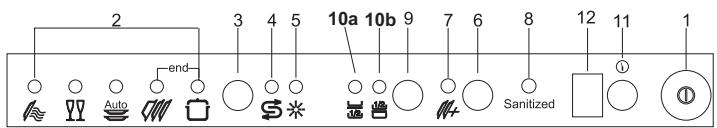
The dishwasher is equipped with a control panel (see fig. 2-02) which is used to program the appliance and switch it on and off.
text_image
2 3 4 5 10a 10b 9 7 6 8 12 11 1 end Auto SanitizedFIG. 2-02
To select the most suitable program for the dishes to wash, consult the following table which specifies the most appropriate type of washing sequence depending on the kind of dishes and how dirty they are (see tabs. 2-02a and 2-02b).
| PROGRAM NUMBER AND SYMBOL | DISHES AND CUTLERY | PROGRAM SEQUENCE | TIME | CONSUMPTION | |||
| MINUTES (2) | WATER (1) | ENERGY kWh (2) | |||||
| 1 |  | DISH WARMING | Pans and dishes to rinse and dry | Rinse at 69°C (156.2°F) Dry. | 50' | 3.9 l 1,03 gal. | 0.64 |
| 2 | [SWIZ] | CRYSTAL | Moderately dirty | Wash at 45°C (113°F)Cold rinse.Rinse at 69°C (156.2°F)Dry. | 70' | 10.8 l 2.85 gal. | 0,6 |
| 3 | [7TBD] | AUTO SUPER WASHETL SANITATION LISTED | Moderately dirty, including dried-on residue | Cold pre-wash (Depending of the type of dirty)Wash at 65°C (149°F).Cold rinse.Hot rinse at 70°C (158°F).Dry. | 115'-130' | 11-15 l 2.91-3.96 gal. | 1-1.2 |
| 4 | [70C0] | NORMAL | Moderately dirty | Cold pre-wash.Wash at 55°C (131°F).Cold rinse.Rinse at 68°C (154.4°F).Dry. | 112' | 14,8 l 3.91 gal. | 0.8 |
| 5 |  | EXTREME WASHETL SANITATION LISTED | Very dirty pans and dishes, including dried-on residue | Pre-wash at 45°C (113°F).Wash at 70°C (158°F)2 cold rinsesRinse at 70°C (158°F)Dry. | 122' | 18,3 l 4.83 gal. | 1.12 |
| Tab. 2-02a | |||||||
| 6 |  | RINSE | Pans and dishes waiting to be washed | Cold pre-wash | 16' | 3.9 l 1.03 gal. | 0.03 |
| 7 |  | SHORT | Slightly dirty | Wash at 38°C (136.40°F) Cold rinse. Rinse at 58°C (136.4°F). | 37' | 10.6 l 2.8 gal. | 0.38 |
| 8 |  | AUTO DELICATE | Wash immediately after use | Cold pre-wash (Depending of the type of dirty) Wash at 55°C (131°F). Cold rinse. Hot rinse at 69°C (156.2°F). Dry. | 105'-120' | 11-15 l 2.91-3.96 gal. | 0.8-1 |
| 9 |  | ECONOMY | Wash immediately after use | Wash at 55°C (131°F). Cold rinse. Rinse at 69°C (156.2°F). Dry. | 123' | 11,9 l 3.14 gal. | 0.9 |
| 10 |  | HEAVY WASH | Moderately dirty pans and dishes, including dried-on residue | Wash at 70°C (158°F) 2 cold rinses. Rinse at 70°C (158°F) Dry. | 102' | 15.1 l 3.99 gal. | 1,0 |
| Tab. 2-02b | |||||||
(1) Average water consumption with the softener set to level 0 (zero).
Any other setting will increase water consumption till 2.5 l (0.66 gal.) / cycles with setting 5.
(2) The cycle times listed in the use and care manual are based on normal soil loads and 120^ F ( 49^ C) incoming water and will vary based on your actual conditions.
- Only “AUTO SUPER WASH” and “EXTREME WASH” programs conforms to NSF std 184 and are certified by INTERTEK with the ETL SANITATION LISTED.
- When the “Sanitized” light shine it means that the dishwasher and its contents have been sanitized according to the requirements of the National Sanitation Foundation (NSF).
- When the “AUTO PROGRAMMES” are selected, the dishwasher recognizes the type of dirt and automatically adjusts the washing parameters as appropriate.
Only run the soak program with half loads.
To run programs 6, 7, 8, 9, 10 (see tab. 2-02b), select the required standard program (see programs 1, 2, 3, 4, 5 in tab. 2-02a) and then press the supplementary program button (ref. 6 fig. 2-02).
After using the above tables to choose the most suitable washing cycle, program the appliance.

Before starting a washing program, make sure that:
- The water supply tap is open.
- There is regenerating salt in the water softener tank (to add salt, see the instructions in the general manual).
- The correct amount of detergent has been added to the dispenser (to add detergent, see the instructions in the general manual).
- The spray arms are able to rotate freely and without obstruction.
- The racks have been correctly loaded (see the instructions in the general manual).
- The dishwasher door is securely closed.
2.2.1 Switching on
Press the on/off button (ref. 1 fig. 2-02) to start the dishwasher. Then wait for one of the program indicator lights to turn on (ref. 2 fig. 2-02).
2.2.2 Selecting and starting the program
- Press the program selection button (ref. 3 fig. 2-02) several times until the indicator light corresponding to the required program turns on (ref. 2 fig. 2-02);
- if required, press the relative buttons to select any complementary functions (e.g.: “half-load”, “program delay”; see para 2.2.7 “options”);
- close the door; the program will start after about 2 seconds and the relative indicator light will flash throughout the cycle (program→ running signal).

If the door of the dishwasher has not been closed or has been incorrectly closed, the washing cycle will not begin.
SUPPLEMENTARY PROGRAMS
The supplementary program button (ref. 6 fig. 2-02) adds five extra programs to the ones that can be directly selected with the program selection button.
Press the button (the indicator light turns on) after selecting the “main” program (see 1, 2, 3, 4, 5 in tab. 2-02a).
As the function is memorized, press the button again (the indicator light turns off) if you wish to run one of the 5 main programs for the next cycle.
2.2.3 End of program
The end of the program is signaled by a short beep. Additionally the indicator light of the normal and strong programs (marked “end”) flash.
2.2.4 Interrupting a program
To interrupt the current program simply open the door of the dishwasher; to restart the program, simply close the door again. The program restarts from where it was interrupted.
2.2.5 Changing the current program
To change the current program, simply open the door of the dishwasher and select the new program. Close the door to run the new program automatically.
2.2.6 Canceling the current program
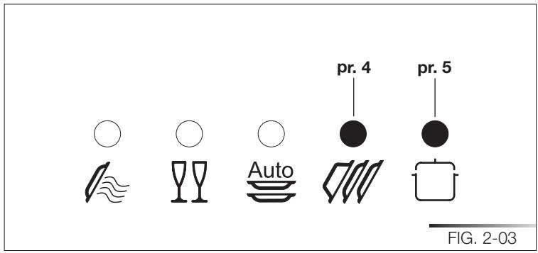
- To cancel the current program, open the door and press and hold down the program selection button (ref. 3 fig. 2-02) for a few seconds until the indicator lights of the fourth and fifth programs turn on (ref. pr. 4, pr. 5 fig. 2-03).
- Close the door again.
- After about 1 minute, the dishwasher terminates the cycle and the indicator lights of the fourth and fifth programs (ref. pr. 4, pr. 5 fig. 2-03) start flashing.
text_image
pr. 4 pr. 5 FIG. 2-032.2.7 Options
HALF-LOAD
(only fitted on some models)
This option is particularly suitable for reduced loads and saves on water and electricity.
Before selecting the half-load wash option, open the dishwasher door and choose the required washing program (see para 2.2 “Setting the washing program and switching on and off”).
The half-load wash cycle can be selected in two different ways using the half-load wash button (ref. 9 fig. 2-02):
- press the button once to select washing in the upper rack. This is confirmed by the relative indicator light (ref. 10a fig. 2-02);
- press the button twice to select washing in the lower rack. This is confirmed by the relative indicator light (ref. 10b fig. 2-02);
- press the button three times to return to the standard full load condition (washing in both racks, both indicator lights off).
When washing in just the lower rack is selected, the cutlery basket can be separated and just half used.
PROGRAM DELAY
(only on some models; available for all programs except soak)
The “Program delay” function delays the beginning of the washing program up to 9 hours from the moment in which programming takes place. This makes it possible to use the dishwasher at a certain time of day.
Before programming a delay, open the door of the dishwasher, select the required washing program (see para 2.2 “Setting the washing program and switching on and off”). Select the day by pressing the Program delay button (ref. 11 fig. 2-02); each time you press the button, the display increases the delay before the appliance starts by 1 hour.
2.2.8 Switching off
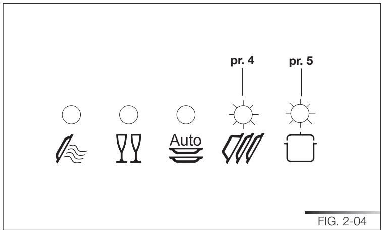
At the end of the program, the dishwasher emits a short beep and the indicator lights of the fourth and fifth program (ref. pr. 4, pr. 5 fig. 2-04) flash.
Turn off the appliance by opening the door and pressing the on/off button (ref. 1 fig. 2-02).
text_image
pr. 4 pr. 5 FIG. 2-042.3 Additional functions
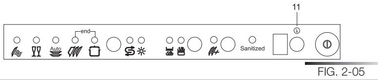
2.3.1 Adjusting the water softener

N.B.: a different washing program from soak must be used to make the following adjustment.
Press and hold down the program delay button (ref. 12 fig. 2-05) until the preset value appears followed by a dot (normally 3.). Release the button and then press it again and again until the required value is displayed, as indicated in the table (see tab. 2-03).
The 6 possible adjustment levels will appear in this sequence:
3., 4., 5., 0., 1., 2..
When the required value appears on the display, release the button; after 5 seconds the appliance automatically reverts to the program delay and the adjustment is set to the chosen value.

N.B.: the display indicates the water hardness adjustment and the program delay. A dot (.) after the number means that the water hardness adjustment is being displayed. If no dot (.) appears, the program delay is being displayed.
text_image
11 ① SAZENIZED FIG. 2-05Water hardness table (see tab. 2-03)
| WATER HARDNESS | SETTING | ||
| German degrees (°D) | French degrees (°F) | American degrees grains/galls | |
| 0 - 4 | 0 - 7 | 0 - 4.5 | 0. |
| 5 - 15 | 8 - 25 | 4.6 - 14.5 | 1. |
| 16 - 23 | 26 - 40 | 14.6 - 23.5 | 2. |
| 24 - 31 | 41 - 60 | 23.6 - 35 | 3. |
| 32 - 47 | 61 - 80 | 35.1 - 46.5 | 4. |
| 48 - 58 | 81 - 100 | 46.6 - 58.5 | 5. |
| Tab. 2-03 | |||
Contact your local water board for information on the hardness of your water supply.

If it is necessary to open the door during the washing cycle, the program will be interrupted, the relative indicator light will continue to flash and a beep will indicate that the cycle has not terminated. Wait for about 1 minute before closing the door and continuing with the program. When the door closes, the program will start from where it was interrupted. This operation should be performed only if necessary as it could cause irregular program performance.
3 ENERGY SAVING AND ENVIRONMENTAL RESPECT
• Always try to run the dishwasher fully loaded.
- Do not wash the dishes under a running tap.
- Use the most suitable washing program for each type of load.
- Do not pre-rinse.
- If available, connect the dishwasher to a hot water system with a temperature of up to 60^ C ( 140^ F).
- When possible, skip the drying cycle by opening the door after washing: the air and the residue heat will dry the dishes to perfection.
3.1 Reducing the consumption of detergent and respecting the environment
The phosphates contained in dishwasher detergents are harmful to the environment. To avoid using excessive amounts of detergent and to save on electricity:
- Separate the more delicate items from those that are more resistant to aggressive detergents and high temperatures;
- Do not pour the detergent directly onto the dishes.
4 REMOVING THE DISHES

At the end of the washing program, wait at least 20 minute before removing the dishes in order to allow them to cool. To prevent any water droplets on the upper rack from falling onto the dishes in the lower rack, empty the lower rack first and then the upper one.
5 TROUBLESHOOTING
The dishwasher can to signal a number of malfunctions by turning on various indicator lights, as described below (see following table):
| FAULT | DESCRIPTION | ||||
| E1 |  [DXC] [ADCW] [BXGA] [AZWS] [Sawasi] [CSOH] [AryWW] [BwzoI] [Asxcl] [DXC] [ADCW] [BXGA] [AZWS] [Sawasi] [CSOH] [AryWW] [BwzoI] [Asxcl] | Acquastop failureThe anti-flooding system has tripped (only for models fitted with this feature). Activates in case of water leaks. Contact the technical assistance service. | |||
| E2 |  [CCSI] [TATA] [HAC] [SHAK] [Asxal] [Dapal] [Asxal] [Bswwi] [Gmazl] [CCSI] [TATA] [HAC] [SHAK] [Asxal] [Dapal] [Asxal] [Bswwi] [Gmazl] | Safety levelThe system limiting the water level in the dishwasher has tripped. Interrupt the current program. Switch off the dishwasher, switch it back on again, program a new cycle and press start. If the problem persists, contact the technical assistance service. | |||
| E3 | [STM] [SWT] [SWK] [VAT] [VWR] [ApoJo] [Gwzi] [Tswwi] [Bswol] [SvncI] _ _ _ _ _ _ _ _ _ _ _ _ _ _ _ _ _ _ _ _ _ _ _ _ _ _ _ _ _ _ _ _ _ _ _ _ _ _ _ _ _ _ _ _ _ _ _ _ _ _ _ _ _ _ _ _ _ _ _ _ _ _ _ _ _ _ _ _ _ _ _ _ _ _ _ _ _ _ _ _ _ _ _ _ _ _ _ _ _ _ _ _ _ _ _ _ _ _ _ _ | Water heating malfunctionThe water is not heated or is incorrectly heated. Repeat the washing program; if the problem persists, contact the technical assistance service. | |||
| E4 | [SAAG] [SSM] [SWK] [VAT] [VWR] [ApoJo] [Dwoi] [CsaoI] [TyrQO] [GmtaI] | Water temperature monitoring malfunctionInterrupt the current program. Switch off the dishwasher, switch it back on again, program a new cycle and press start. If the problem persists, contact the technical assistance service. | |||
| E5 | [HEY] [MSU] [MSI] [VARK] [VTR] [Dwtyi] [Dwww] [Osasl] [Bswol] [Aswri] _ _ _ _ _ _ _ _ _ _ _ _ _ _ _ _ _ _ _ _ _ _ _ _ _ _ _ _ _ _ _ _ _ _ _ _ _ _ _ _ _ _ _ _ _ _ _ _ _ _ _ _ _ _ _ _ _ _ _ _ _ _ _ _ _ _ _ _ _ _ _ _ _ _ _ _ _ _ _ _ _ _ _ _ _ _ _ _ _ _ _ _ _ _ _ _ _ _ | Water intake malfunctionThe appliance does not take in water or does so incorrectly. Make sure the water connections are correct, that the water supply tap is open and that the filter is not clogged. If the problem persists, contact the technical assistance service. | |||
| Tab. 5-01a | |||||
Tab. 5-01a
| FAULT | DESCRIPTION | |
| E6 |  | Water pump-out malfunctionThe appliance does not pump out the water or does so incorrectly. Make sure the drain hose is not kinked or crushed and that the siphon and filters are not clogged. If the problem persists, contact the technical assistance service. |
| E7 |  | Turbine flow-regulator malfunction(only for models fitted with this feature)The appliance is unable to precisely measure the quantity of incoming water. Interrupt the current program and switch off the dishwasher. Switch it back on again, program a new cycle and press start. If the problem persists, contact the technical assistance service. |
| E8 |  | Alternate washing system malfunctionInterrupt the current program and switch off the dishwasher. Switch it back on again, program a new cycle and press start. If the problem persists, contact the technical assistance service. |
| E9 |  | Water intake system malfunctionContact the technical assistance service. |
| Tab. 5-01b | ||

Light off

Light on

Light flashing
If an alarm situation occurs, the dishwasher interrupts the current program and signals the fault.
- Alarms E1, E2, E3, E4, E8, E9 immediately terminate the current program.
- Alarms E5, E6 interrupt the current program and, after the problem has been eliminated, resume the cycle.
- Alarm E7 is displayed at the end of the cycle which, however, is completed given that it does not jeopardize the operation of the dishwasher.
To "reset" an alarm:
- open or close the door, or switch the appliance on and back off again. At this point, the dishwasher can be programmed again.

If the fault persists, contact the Authorized Technical Assistance Service.
Contents
1 INTRODUCTION 3
2 IMPORTANT SAFETY INSTRUCTION....5
3 INSTALLATION AND HOOK-UP 12
4 OPERATING INSTRUCTIONS 15
4.1 Using the water softening system....16
4.2 Using the rinse-aid and detergent dispensers....18
4.2.1 Adding the rinse-aid....19
4.2.2 Adjusting the rinse-aid dispenser system....19
4.2.3 Adding the detergent 20
4.3 General warnings and recommendations 22
4.4 Using the racks....24
4.4.1 Lower rack....25
4.4.2 Cutlery basket....27
4.4.3 Upper rack....29
5 CLEANING AND USER-MAINTENANCE 34
5.1 General warnings and recommendations for correct maintenance......34
5.2 Cleaning the water intake filter....35
5.3 Cleaning the spray arms....35
5.4 Cleaning the filter unit....37
5.5 Maintenance warnings and advice ....38
5.6 Troubleshooting minor problems 39
6 TECHNICAL DATA 41
1 INTRODUCTION
Thank you for choosing one of our products. To use this dishwasher correctly and safely, please read this manual carefully. The manual is divided into sections giving you a step-by-step guide to all your appliance's functions. The texts are easy to understand and are complete with detailed illustrations. Following the cleaning instructions provided here will keep dishwasher performance at peak levels in the long term. This user-friendly manual will provide answers to all your questions about use of the dishwasher.
This manual comprises the following sections:
INTRODUCTION: general information about the manual.
WARNINGS: a list of warnings concerning safety and use of the dishwasher.
INSTALLATION INSTRUCTIONS: for the qualified technician who must carry out the installation, hook-up and testing of the appliance.
USER INSTRUCTIONS: useful advice is provided for the use of racks, spray arms, containers and filters.
Nomenclature of figures and tables:
The progressive number of each figure is shown in the bottom right-hand corner of the relative box. An example of a progressive number is “Fig. 4-01”, where the first number (4) indicates the section to which the figure belongs, while the second number (01) indicates the progressive number of the figure in section 4 (Fig. 4-01 is the first figure in section 4). The tables are numbered in the same way, bearing in mind that “Tab.” is used instead of “Fig.” (e.g.: Tab. 4-01 is the first table in section 4). If a table occupies more than one page, a letter is added after the progressive number (e.g.: “Tab. 4-01a”, Tab. 4-01b”).
Symbols used in this manual (see tab. 1-01)
 | DANGER. This symbol highlights information and warnings which, if not observed, may compromise personal safety or damage the appliance. |
 | DANGER OF ELECTROCUTION. This symbol highlights information and warnings of an electrical nature which, if not observed, may compromise personal safety or damage the appliance. |
 | This symbol highlights general information and warnings. |
| Tab. 1-01 | |
2 IMPORTANT SAFETY INSTRUCTION (Save this instructions)

THIS MANUAL FORMS AN INTEGRAL PART OF THE APPLIANCE: IT MUST ALWAYS BE KEPT INTACT TOGETHER WITH THE DISHWASHER (INCLUDING THE "INSTALLATION" AND "DESCRIPTION OF CONTROLS" MANUALS, IF ATTACHED). BEFORE USING THE APPLIANCE, CAREFULLY READ ALL THE INSTRUCTIONS CONTAINED IN THIS MANUAL. INSTALLATION MUST BE PERFORMED BY A QUALIFIED TECHNICIAN, IN COMPLIANCE WITH THE REGULATIONS IN FORCE. THIS APPLIANCE IS INTENDED FOR DOMESTIC USE, AND COMPLIES WITH THE DIRECTIVES CURRENTLY IN FORCE, INCLUDING THE PREVENTION AND ELIMINATION OF RADIO FREQUENCY INTERFERENCE. THE APPLIANCE IS DESIGNED FOR THE FOLLOWING PURPOSE: WASHING AND DRYING OF DISHES; ANY OTHER USE SHALL BE CONSIDERED IMPROPER. THE MANUFACTURER DECLINES ALL RESPONSIBILITY FOR USES OTHER THAN THOSE DESCRIBED ABOVE.

THE NAME PLATE FEATURING THE TECHNICAL DATA, SERIAL NUMBER AND MARKINGS IS VISIBLY POSITIONED ON THE INNER EDGE OF THE DOOR. THE NAME PLATE MUST NEVER BE REMOVED.

THIS APPLIANCE IS NOT SUITABLE FOR USE ON BOATS, CARAVANS OR THE LIKE. DISHWASHERS CERTIFIED FOR DOMESTIC USE ARE NOT SUITABLE FOR AUTHORISED FOOD FACTORIES.

CHECK THAT THE VOLTAGE, FREQUENCY AND PROTECTION OF THE DOMESTIC MAINS POWER SUPPLY MATCH THE RATINGS ON THE NAME PLATE OF THE APPLIANCE.

DO NOT LEAVING DISCARDED PACKAGING MATERIALS UNSUPERVISED WITHIN THE HOME. SEPARATE THE VARIOUS PACKAGING MATERIALS AND TAKE THEM TO THE NEAREST SORTED WASTE COLLECTION CENTRE. KEEP CHILDREN, PHYSICALLY AND/OR MENTALLY IMPAIRED ADULTS, AND ANIMALS AWAY FROM PACKAGING WASTE; DANGER OF SUFFOCATION.

BEFORE PROCEEDING WITH INSTALLATION, DISCONNECT THE MAINS POWER SUPPLY FROM THE WORK AREA.

DO NOT USE EXTENSION CORDS, ADAPTORS OR SHUNT CONNECTIONS IN ORDER TO AVOID THE POSSIBILITY OF OVERHEATING OR BURNING WITH CONSEQUENT FIRE HAZARD.

DURING INSTALLATION, TAKE CARE NOT TO INJURE YOURSELF ON THE SHARP EDGES OF THE APPLIANCE; WEAR SAFETY GLOVES.

THE APPLIANCE MUST BE PROVIDED WITH AN EARTH CONNECTION IN ACCORDANCE WITH THE ELECTRICAL SAFETY REGULATIONS IN FORCE. IF IN DOUBT, HAVE THE SYSTEM CHECKED BY A QUALIFIED ELECTRICIAN (SEE ALSO THE WARNINGS INDICATED IN CHAPTER 3).
THE MANUFACTURER DECLINES ALL RESPONSIBILITY FOR DAMAGE TO PERSONS OR PROPERTY RESULTING FROM THE FAILURE TO EARTH THE APPLIANCE OR FROM A DEFECTIVE EARTH CONNECTION.

ALWAYS SWITCH OFF THE DISHWASHER AFTER EACH USE TO AVOID WASTING ELECTRICITY.

IN THE EVENT OF A FAULT, DISCONNECT THE DISHWASHER FROM THE ELECTRICAL POWER SUPPLY AND SHUT OFF THE WATER TAP.

DO NOT USE APPLIANCES WHICH HAVE BEEN DAMAGED DURING TRANSIT! IF IN DOUBT, CONSULT YOUR DEALER. THE APPLIANCE MUST BE INSTALLED AND CONNECTED IN ACCORDANCE WITH THE INSTRUCTIONS PROVIDED BY THE MANUFACTURER OR BY A QUALIFIED TECHNICIAN.

ONLY USE DETERGENTS SPECIALLY FORMULATED FOR DISH-WASHERS. DO NOT USE DETERGENTS FORMULATED FOR WASHING DISHES BY HAND.
ONLY USE RINSE-AID SPECIALLY FORMULATED FOR DOMESTIC DISHWASHERS.

DO NOT INHALE OR SWALLOW DETERGENT AS THIS MAY CAUSE BURNS AND/OR PERMANENT DAMAGE TO THE NOSE, MOUTH AND THROAT, AND EVEN LEADING TO SUFFOCATION; KEEP DETERGENT AWAY FROM YOUR EYES. IF ONE OF THE ABOVE SITUATIONS OCCURS, SEEK MEDICAL ASSISTANCE IMMEDIATELY. TO PREVENT CHILDREN FROM COMING INTO CONTACT WITH DETERGENT, FILL THE DISHWASHER JUST BEFORE STARTING THE WORK PROGRAM AND THEN KEEP THE DETERGENT OUT OF THE REACH OF CHILDREN.

THIS DISHWASHER MUST BE USED BY ADULTS. USE BY PERSONS WITH REDUCED MENTAL AND/OR PHYSICAL CAPABILITIES IS ONLY PERMITTED UNDER THE SUPERVISION OF A PERSON RESPONSIBLE FOR THEIR SAFETY.
DO NOT ALLOW CHILDREN TO APPROACH AND/OR PLAY IN OR ON THE DISHWASHER. THE APPLIANCE MAY CONTAIN RESIDUES OF DETERGENT WHICH CAN CAUSE PERMANENT DAMAGE TO THE EYES, MOUTH AND THROAT, AS WELL AS POSSIBLE DEATH BY SUFFOCATION; IF THE ABOVE OCCURS, SEEK MEDICAL ASSISTANCE IMMEDIATELY.
BEWARE; IT IS POSSIBLE FOR CHILDREN TO GET TRAPPED INSIDE THE DISHWASHER!

DO NOT INTRODUCE SOLVENTS SUCH AS ALCOHOL OR TURPENTINE WHICH MAY CAUSE AN EXPLOSION.
DO NOT POUR POWDER AND/OR LIQUID DETERGENT INTO THE RINSE-AID CONTAINER AS THIS WILL DAMAGE THE CONTAINER. DO NOT POUR POWDER AND/OR LIQUID DETERGENT INTO THE WASTER SOFTENER TANK AS THIS WILL DAMAGE THE TANK. DO NOT USE INDUSTRIAL DETERGENTS AS THIS MAY DAMAGE THE APPLIANCE AND/OR TRIGGER VIOLENT CHEMICAL REACTIONS (E.G. EXPLOSIVE GAS).

DO NOT LOAD DISHES THAT ARE SOILED WITH ASH, WAX OR PAINTS.

DO NOT INTRODUCE ITEMS IN HEAT-SENSITIVE PLASTI-C, SUCH AS DISPOSABLE CUTLERY OR PLATES, AS THESE MAY BECOME DEFORMED. DO NOT WASH OBJECTS IN PLASTIC UNLESS THEY ARE MARKED "DISHWASHER PROOF" OR THE LIKE. FOR UNMARKED OBJECTS, FOLLOW THE INSTRUCTIONS OF THE MANUFACTURER; IF NO INFORMATION IS AVAILABLE, DO NOT WASH THESE OBJECTS IN THE DISHWASHER.

DO NOT INTRODUCE ANIMALS INTO THE DISHWASHER.

WHEN OPENING THE DISHWASHER DOOR DURING A CYCLE THERE IS A RISK OF SCALDING DUE TO THE HEAT CONTAINED INSIDE; DO NOT GET IN THE WAY OF THE STEAM LEAVING THE APPLIANCE AND DO NOT TOUCH THE COMPONENTS INSIDE. WAIT 20 MINUTES AFTER THE END OF THE WASHING CYCLE OR AFTER INTERRUPTING IT BEFORE REMOVING THE DISHES IN ORDER TO ALLOW THEM TO DRY.

IN CERTAIN SITUATIONS, HYDROGEN MAY BE GENERATED INSIDE A HOT WATER SYSTEM THAT HAS NOT BEEN USED FOR OVER TWO WEEKS. HYDROGEN IS AN EXPLOSIVE GAS. IF THE HOT WATER SYSTEM HAS NOT BEEN USED FOR TWO WEEKS OR MORE, OPEN ALL THE HOT WATER TAPS AND ALLOW THE WATER TO RUN FOR A FEW MINUTES BEFORE USING THE DISHWASHER. THIS WILL DISCHARGE ANY HYDROGEN BUILDUPS.
AS THIS GAS IS FLAMMABLE, DO NOT SMOKE OR USE NAKED FLAMES WHILE PERFORMING THIS OPERATION.

LEANING OR SITTING ON THE DISHWASHER DOOR WHEN OPEN MAY CAUSE THE APPLIANCE TO OVERTURN, PUTTING PEOPLE AT RISK. NEVER LEAVE THE DISHWASHER DOOR OPEN; PEOPLE MIGHT TRIP OVER IT.
DO NOT LEAN AGAINST OR STAND ON THE DISHWASHER RACKS.

DO NOT DRINK THE WATER RESIDUES WHICH MAY BE PRESENT INSIDE THE DISHES OR DISHWASHER.
KNIVES OR OTHER SHARP-ENDED COOKING UTENSILS MUST BE PLACED IN THE CUTLERY BASKET BLADE-DOWN, OR LAID HORIZONTAL IN THE UPPER RACK. TAKE CARE NOT TO CUT YOURSELF AND ENSURE THAT THEY DO NOT PROJECT FROM THE RACK.
POSITION SHARP/POINTED OBJECTS SO AS TO PREVENT THEM FROM DAMAGING THE DOOR GASKETS.

text_image
Three warning symbols: triangular warning triangle with exclamation mark, triangular warning triangle with exclamation mark, and lightning bolt symbol.DO NOT OPERATE THE DISHWASHER UNLESS ALL THE OUTER PANELS HAVE BEEN POSITIONED CORRECTLY.
DO NOT TAMPER WITH THE DISHWASHER CONTROLS.
AQUASTOP MODELS; THE AQUASTOP DEVICE PREVENTS FLOODING IN THE EVENT OF A WATER LEAK. WHEN THE AQUASTOP DEVICE IS TRIPPED (THE ERROR IS INDICATED ON THE DISPLAY), CALL IN A QUALIFIED TECHNICIAN TO IDENTIFY AND REPAIR THE FAULT. IN MODELS EQUIPPED WITH THE AQUASTOP DEVICE, THERE IS A SOLENOID VALVE INSIDE THE WATER INTAKE HOSE. DO NOT CUT THE HOSE AND DO NOT ALLOW THE SOLENOID VALVE TO DROP INTO WATER. IN THE EVENT OF DAMAGE TO THE WATER INTAKE HOSE, DISCONNECT THE APPLIANCE FROM THE ELECTRICAL POWER SUPPLY AND FROM THE WATER SUPPLY.
IMMEDIATELY AFTER INSTALLING THE DISHWASHER, PERFORM A QUICK TEST OF THE APPLIANCE (SEE "INSTALLATION" MANUAL). IF THE DISHWASHER FAILS TO OPERATE CORRECTLY, DISCONNECT IT FROM THE ELECTRICAL POWER SUPPLY AND CALL THE NEAREST TECHNICAL SERVICE CENTRE. DO NOT ATTEMPT TO REPAIR THE APPLIANCE.

THE DISHWASHER MEETS ALL THE REQUIREMENTS SET OUT BY THE REGULATIONS IN FORCE CONCERNING SAFETY AND ELECTRICAL EQUIPMENT. ANY TECHNICAL CHECKS SHOULD BE CONDUCTED EXCLUSIVELY BY A TRAINED AND AUTHORIZED TECHNICIAN: REPAIRS CARRIED OUT BY UNAUTHORIZED PERSONS WILL INVALIDATE THE WARRANTY, AS WELL AS POSING A POTENTIAL HAZARD TO THE USER.

BEFORE CLEANING OR SERVICING THE APPLIANCE, REMOVE THE PLUG OR TURN OFF THE MULTI-POLE SWITCH.

REMOVE THE WASHING COMPARTMENT DOOR AND DISCONNECT THE MAINS POWER SUPPLY WHEN REMOVING THE OLD DISHWASHER FOR MAINTENANCE OR DISPOSAL.
THE SYMBOL ON THE PRODUCT, OR ON THE DOCUMENTS ACCOMPANYING THE PRODUCT, INDICATES THAT THIS APPLIANCE MAY NOT BE TREATED AS HOUSEHOLD WASTE. INSTEAD IT SHALL BE HANDED OVER TO THE APPLICABLE COLLECTION POINT FOR THE RECYCLING OF ELECTRICAL AND ELECTRONIC EQUIPMENT. DISPOSAL MUST BE CARRIED OUT IN ACCORDANCE WITH LOCAL ENVIRONMENTAL REGULATIONS FOR WASTE DISPOSAL. FOR MORE DETAILED INFORMATION ABOUT TREATMENT, RECOVERY AND RECYCLING OF THIS PRODUCT, PLEASE CONTACT YOUR LOCAL CITY OFFICE, YOUR HOUSEHOLD WASTE DISPOSAL SERVICE OR THE SHOP WHERE YOU PURCHASED THE PRODUCT.

BY ENSURING THIS PRODUCT IS DISPOSED OF CORRECTLY, YOU WILL HELP PREVENT POTENTIAL NEGATIVE CONSEQUENCES FOR THE ENVIRONMENT AND HUMAN HEALTH.

THE MANUFACTURER DECLINES ALL RESPONSIBILITY FOR DAMAGE TO PERSONS, ANIMALS OR PROPERTY RESULTING FROM FAILURE TO OBSERVE THE ABOVE PRECAUTIONS, FROM TAMPERING WITH EVEN A SINGLE COMPONENT OF THE APPLIANCE, OR FROM THE USE OF UNORIGINAL SPARE PARTS.
IF IN DOUBT ABOUT THE CONTENTS OF THIS MANUAL, CONTACT THE TECHNICAL ASSISTANCE SERVICE.
3 INSTALLATION AND HOOK-UP
To install and hook up this appliance, consult the attached installation manual.
Bear in mind the following warnings when installing and hooking up the dishwasher.

DURING INSTALLATION, TAKE CARE NOT TO INJURE YOURSELF ON THE SHARP EDGES OF THE APPLIANCE; WEAR SAFETY GLOVES.

INSTALLATION, REPAIRS AND SERVICING MUST BE PER- FORMED BY QUALIFIED AND AUTHORIZED TECHNICIANS.
AS WELL AS INVALIDATING THE WARRANTY, WORK CARRIED OUT BY UNAUTHORIZED PERSONS MAY GENERATE HAZARDS. INSTALLATION MUST BE PERFORMED IN COMPLIANCE WITH ALL THE DIRECTIVES IN FORCE IN THE COUNTRY OF INSTALLATION AND, IF THESE DO NOT EXIST: IN THE UNITED STATES THE NATIONAL ELECTRIC CODE; IN CANADA THE CANADIAN ELECTRIC CODE C22.1 - LATEST EDITION/PROVINCIAL AND MUNICIPAL CODES AND/OR LOCAL CODES.

BUILDING-IN A DISHWASHER UNDERNEATH A CERAMIC HOB IS ABSOLUTELY FORBIDDEN. A DISHWASHER CAN BE BUILT-IN UNDERNEATH A CONVENTIONAL HOB PROVIDED THERE IS NO BREAK IN THE KITCHEN WORKTOP, AND THE DISHWASHER AND HOB ARE INSTALLED AND SECURED CORRECTLY, SO THAT NO HAZARDS ARE GENERATED.

PREVENTING THE RISK OF CLOGGING OR DAMAGE: IF THE WATER PIPE IS NEW OR HAS NOT BEEN USED FOR A LONG TIME, BEFORE CONNECTING TO THE WATER SUPPLY CHECK THAT THE WATER IS CLEAR AND FREE OF IMPURITIES, TO PREVENT DAMAGE TO THE APPLIANCE. THE DISHWASHER MUST ALWAYS BE CONNECTED TO THE WATER SYSTEM WITH NEW HOSES; OLD OR USED HOSES MUST NEVER BE REUSED.

CHECK THAT THE VOLTAGE AND THE FREQUENCY OF THE MAINS MATCH THE RATINGS ON THE NAME PLATE OF THE APPLIANCE POSITIONED ON THE INNER EDGE OF THE DOOR.

IN THE EVENT OF DAMAGE TO THE SUPPLY CORD, HAVE IT REPLACED BY THE MANUFACTURER OR AN AUTHORIZED TECH-NICAL SERVICE CENTRE.
THIS APPLIANCE MUST BE EARTHED. IN CASE OF A MALFUNCTION OF FAULT, THE EARTH REDUCES THE RISK OF ELECTROCUTION BY PROVIDING THE ELECTRICAL CURRENT WITH AN ALTERNATIVE, LESS RESISTANT PATH.

BEFORE MAKING ELECTRICAL CONNECTIONS, DISCONNECT THE MAINS POWER SUPPLY FROM THE WORK AREA.

CHECK THAT THE MAINS SUPPLY IN THE PLACE OF INSTALLATION COMPLIES WITH THE REGULATIONS IN FORCE IN THE COUNTRY OF USE, AND THAT IT IS CORRECTLY EARTHED.

THIS APPLIANCE MUST BE EARTHED. IN CASE OF A MALFUNCTION OF FAULT, THE EARTH REDUCES THE RISK OF ELECTROCUTION BY PROVIDING THE ELECTRICAL CURRENT WITH AN ALTERNATIVE, LESS RESISTANT PATH. THIS APPLIANCE IS FITTED WITH A SUPPLY CORD CONTAINING AN EARTH WIRE AND PLUG. FIT THE PLUG INTO A SUITABLE SOCKET, INSTALLED AND EARTHED IN COMPLIANCE WITH THE LAWS IN FORCE IN THE COUNTRY OF INSTALLATION.

AN INCORRECTLY CONNECTED EARTH WIRE MAY GENERATE THE RISK OF ELECTROCUTION. IF IN DOUBT AS TO THE CORRECT EARTHING OF THE APPLIANCE, CALL IN A QUALIFIED ELECTRICIAN OR THE TECHNICAL ASSISTANCE SERVICE. DO NOT CHANGE THE PLUG ATTACHED TO THE APPLIANCE. IF THE PLUG IS NOT SUITABLE FOR THE SOCKET, CALL IN A QUALIFIED ELECTRICIAN TO FIT A SUITABLE PLUG.

IN THE EVENT OF DAMAGE TO THE SUPPLY CORD, HAVE IT REPLACED BY THE MANUFACTURER OR AN AUTHORIZED TECHNICAL SERVICE CENTRE IN ORDER TO AVOID ANY RISK.

DO NOT USE EXTENSION CORDS, ADAPTORS OR SHUNT CONNECTIONS IN ORDER TO AVOID THE POSSIBILITY OF OVERHEATING OR BURNING, WITH CONSEQUENT FIRE HAZARD.
4 OPERATING INSTRUCTIONS

BEFORE STARTING TO USE THE APPLIANCE, MAKE SURE YOU HAVE READ AND UNDERSTOOD ALL THE WARNINGS CONTAINED IN CHAPTER 2 "IMPORTANT SAFETY INSTRUCTION".
Once the dishwasher has been correctly installed, prepare for use as follows:
- adjust the water softening system;
- add the regenerating salt;
- add the rinse-aid and detergent.
4.1 Using the water softening system
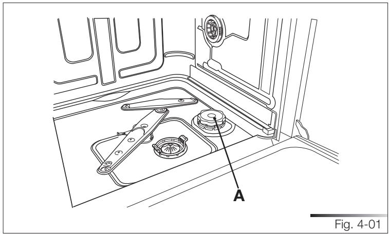
The amount of scale contained in the water (water hardness index) can cause whitish staining on the dry dishes, which tend to become dull over time. The dishwasher is equipped with an automatic softening system which uses a special regenerating salt to reduce the hardness of the water. The dishwasher is factory set for water hardness level 3 (average hardness 41-60^ - 24-31^ / 23.6-35 gpg). When using water of medium hardness, the regenerating salt container should be refilled after approximately 20 washing cycles. The salt container can hold approximately 1.7 Kg (3.75 lb) of salt in grains. Some models are equipped with an optical no-salt indicator. In these models, the cap of the salt container contains a green float which descends as the salt concentration in the water drops. When the green float can no longer be seen, the container must be topped up with regenerating salt. The container is situated at the bottom of the dishwasher. After removing the lower rack, unscrew the salt container cap (ref. A fig. 4-01) by turning it anticlockwise and pour in the salt using the funnel (ref. A fig. 4-02) supplied with the dishwasher. Before replacing the cap (ref. A fig. 4-01), remove any salt residues from around the opening.
text_image
A Fig. 4-01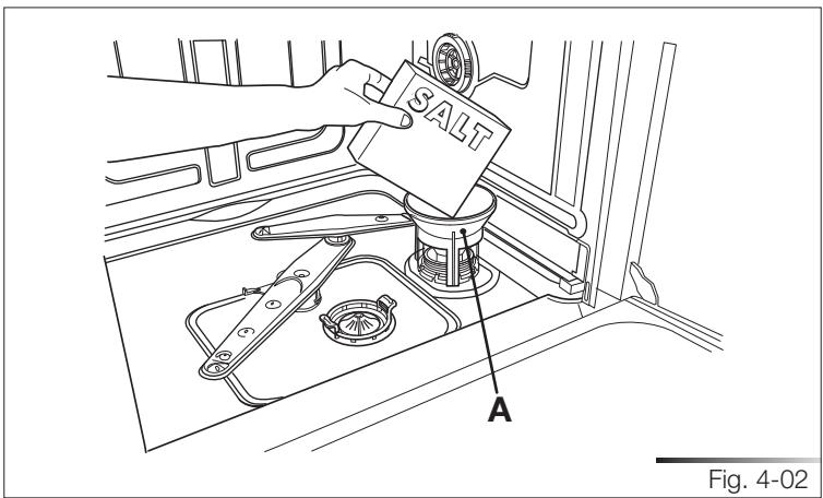
text_image
SALT A Fig. 4-02- When using the dishwasher for the first time, in addition to the salt it is also necessary to add one liter of water to the container.
- Each time the salt container is refilled, make sure that the cap (ref. A fig. 4-01) is securely closed. The mixture of water and detergent must never penetrate the salt container, as this would compromise the operation of the regeneration system. In the event of this occurring, the warranty will be invalidated.
- Only use regenerating salt specially formulated for domestic dishwashers. If using salt tablets, do not fill the container completely.
- Do not use table salt as it contains insoluble substances which, over time, may damage the water softening system.
- When necessary, refill the regenerating salt container before starting the washing program. In this way, the excess saline solution will be immediately removed by the water; the prolonged presence of salt water inside the tank may lead to corrosion.

BE CAREFUL NOT TO CONFUSE THE SALT AND DETERGENT
PACKAGES; ADDING DETERGENT TO THE SALT CONTAINER
WILL DAMAGE THE WATER SOFTENING SYSTEM.
4.2 Using the rinse-aid and detergent dispensers
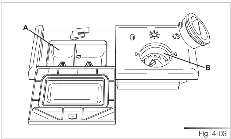
The detergent and rinse aid dispensers are situated on the inner part of the door: the detergent dispenser (ref. A fig. 4-03) is on the left, and the rinse-aid dispenser (ref. B fig. 4-03) is on the right.
text_image
A B Fig. 4-03
WITH THE EXCEPTION OF THE SOAK PROGRAM, BEFORE EVERY WASHING CYCLE IT IS NECESSARY TO ADD THE REQUIRED AMOUNT OF DETERGENT TO THE DETERGENT DISPENSER. THE RINSE AID, ON THE OTHER HAND, SHOULD ONLY BE ADD-ED AS REQUIRED.
4.2.1 Adding the rinse-aid
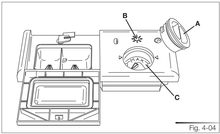
The rinse aid helps the dishes dry faster and prevents the formation of scale deposits and staining; it is automatically added to the water during the final rinse cycle, from the container situated on the inner side of the door.
text_image
B A C Fig. 4-04To add rinse aid:
- Open the door.
- Rotate the container cover (ref. A fig. 4-04) anticlockwise by 14 of a turn and remove it.
- Add the rinse aid until the container is full (approximately 140 ml). The optical level indicator (ref. B fig. 4-04), on the side of the cap should be completely obscured. Refill the rinse aid when the optical level indicator becomes clear again, or when the rinse aid warning light illuminates (see “Description of controls” manual).
- Replace the cover (ref. A fig. 4-04) by turning it in a clockwise direction until it is fully closed.
- Use a cloth to remove any spillage of rinse aid which might lead to the formation of excess foam.
4.2.2 Adjusting the rinse-aid dispenser setting
The rinse-aid dispenser can be set to one of 6 different levels. The dishwasher is factory set for medium water hardness (selector set to “3”). To change the setting, turn the dispenser selector (ref. c fig. 4-04) to the desired position: the amount of rinse-aid dispensed is proportional to the position of this selector. Make sure that the minimum amount of rinse-aid (selector turned to “1”) is approximately 1 ml and the maximum amount (selector turned to “6”) is approximately 6 ml.
- To adjust the rinse aid setting, rotate the dispenser cover (ref. A fig. 4-04) through a quarter turn in an anticlockwise direction and remove it.
- Then use a screwdriver to rotate the rinse aid selector to the desired position.
- Replace the cover (ref. A fig. 4-04) by turning it in a clockwise direction until it is fully closed.
- The amount of rinse aid must be increased if the washed dishes appear dull or feature circular stains.
- If, on the other hand, the dishes are sticky or have white streaks, it is necessary to reduce the rinse aid setting.
4.2.3 Adding the detergent

DO NOT INHALE OR SWALLOW DETERGENT AS THIS MAY CAUSE BURNS AND/OR PERMANENT DAMAGE TO THE NOSE, MOUTH AND THROAT, AND EVEN LEADING TO SUFFOCATION; KEEP DETERGENT AWAY FROM YOUR EYES. IF ONE OF THE ABOVE SITUATIONS OCCURS, SEEK MEDICAL ASSISTANCE IMMEDIATELY. PREVENT CHILDREN FROM COMING INTO CONTACT WITH DETERGENT; KEEP THEM AWAY FROM THE DISHWASHER WHEN THE DOOR IS OPEN AS IT MAY CONTAIN DETERGENT RESIDUES. FILL THE DISHWASHER JUST BEFORE STARTING THE WASHING CYCLE AND THEN KEEP THE DETERGENT OUT OF THE REACH OF CHILDREN.
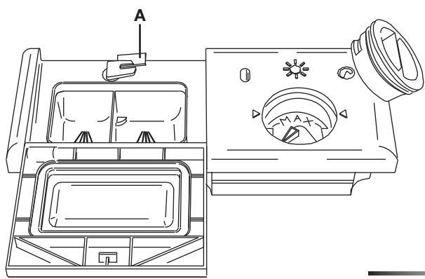
To open the detergent dispenser cover, lightly press the relative button (ref. A fig. 4-05). Add the detergent and close the cover carefully, pushing down on the arrow (ref. B fig. 4-05). During the washing cycle, the dispenser will be opened automatically.
natural_image
Technical line drawing of a washing machine with labeled components (no text or symbols present)Fig. 4-05
text_image
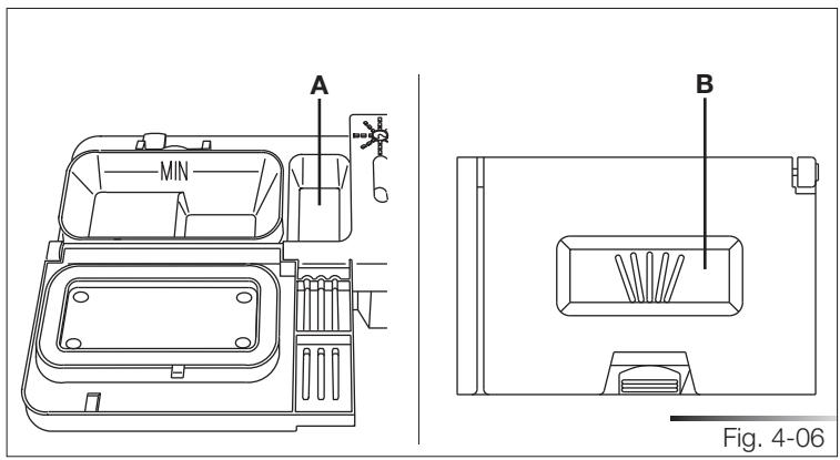
A MIN B Fig. 4-06- When a program with hot prewash is selected (see program table in the “Description of Controls” manual), extra detergent must be placed in the cavity (ref. A or B fig. 4-06, depending on models).
- Only use dishwasher-specific detergents. For optimal washing results it is important to use a good quality detergent.
- The detergent packs must be sealed and stored in a dry place to prevent the formation of lumps which may negatively affect washing results. Once opened the detergent packs should not be kept for too long, otherwise the detergent loses its effectiveness.
- Do not use detergents formulated for washing dishes by hand, because they produce a great deal of foam and may negatively affect the operation of the dishwasher.
- Add the correct amount of detergent. An insufficient amount of detergent will result in a partial removal of dirt from the dishes, whereas an excessive amount is wasteful and does not improve the washing results.
- The market offers liquid and powder detergents with differing chemical compositions, which may contain phosphates, or be phosphate-free but contain natural enzymes.
- Detergents containing phosphates are more effective against grease and starch at temperatures above 60°C (140°F).
- Enzyme detergents, on the other hand, are also effective at lower temperatures (from 40 to 55°C / from 104 to 131°F) and are more easily biodegradable. With enzyme detergents it is possible to obtain at low temperatures comparable results to those which can only be achieved at 65°C (149°F) using traditional detergents. For the safeguarding of the environment we recommend the use of phosphate- and chlorine-free detergents.
- When using detergent tabs, place them in the cutlery basket. The dispenser has been designed for powder or liquid detergent. As the cover does not open completely during the washing cycle, tabs are not fully released (dissolved). This could generate the following problems:
- insufficient detergent released during the cycle and poor washing results;
- the detergent is compacted in the dispenser and is released during the final rinse cycle.

THE INTRODUCTION OF DETERGENT INTO THE RINSE AID DISPENSER, EVEN IN LIQUID FORM, WILL DAMAGE THE DISH-WASHER.
4.3 General warnings and recommendations
Before using the dishwasher for the first time, it is advisable to read the following recommendations concerning dish types to be washed and their loading. There are generally no constraints on the washing of domestic dishes, but in certain cases it is necessary to take their characteristics into account. Before loading the dishes into the racks it is necessary to:
- remove coarse food remains: e.g. bones, fish-bones, etc. which may clog the filter or damage the wash pump;
- soak any pots or pans with burnt-on food remains on the bottom to facilitate removal, then load them into the LOWER RACK.
Use the “ 12 load wash” option (if available) for washing small amounts of dishes; it saves water and electricity. When using this function, only load the rack selected for the 12 load wash; the other rack must remain empty. There is no need to pre-wash the dishes under running water before loading them into the racks since this only wastes water. Correct loading of the dishes helps ensure optimal washing results.
WARNING!
- make sure that the dishes are securely in place so that they cannot tip over or obstruct the rotation of the spray arms during the washing cycle;
- do not place very small objects in the racks as these could fall and obstruct the spray arms or the wash pump;
- containers such as cups, bowls, glasses and pots should always be loaded with the opening facing downwards and with any cavities at an angle, to allow the water to drain out;
- do not stack dishes or place them in such a way that they cover one other;
- do not place glasses too close together because they may knock against each other and break, or there might be staining at the point where they touch.
MAKE SURE that the items being washed are dishwasher-safe.
Items which are not dishwasher-safe:
- Wooden dishes, pots or pans: these may be damaged by the high washing temperatures.
- Handcrafted items: these are rarely suitable for washing in a dishwasher. The relatively high water temperatures and the detergents used may damage them.
- Lightweight objects: place lightweight objects in the upper rack where the water pressure is lower.
- Dishes and objects in copper, tin, zinc or brass: these tend to stain.
- Aluminum dishes: items made from anodized aluminum may lose their color.
• Silverware: silver items may stain. - Glass and crystal: in general, glass and crystal objects can be washed in the dishwasher. However, certain types of glass and crystal may become dull and lose their clearness after many washings. Therefore, for these items we recommend using the least aggressive program available (see “Description of controls” manual).
- Decorated items: the decorated objects available on the market are generally able to withstand washing in the dishwasher, although the colors may fade after a great many washes. If in doubt as to the fastness of the colors, it is advisable to wash just a few items at a time for approximately one month.
4.4 Using the racks
The dishwasher has a capacity of 12 place-settings, including serving dishes.
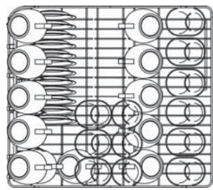
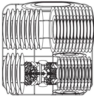
Examples of loading 12 place-settings in the upper rack (see fig. 4-07) and in the lower rack (see fig. 4-08) are shown below.
natural_image
Pure technical diagram of mechanical components arranged in a grid layout (no text or symbols)Fig. 4-07
natural_image
Technical line drawing of a mechanical assembly with multiple helical components (no text or symbols)Fig. 4-08
4.4.1 Lower rack
The lower rack receives the full force of the lower spray arm, and should therefore be used for the “toughest” items with a heavier degree of soiling.
All types and combinations of loads are permitted, provided that the dishes, pots and pans are arranged with all the soiled surfaces exposed to the water jets coming from the bottom.
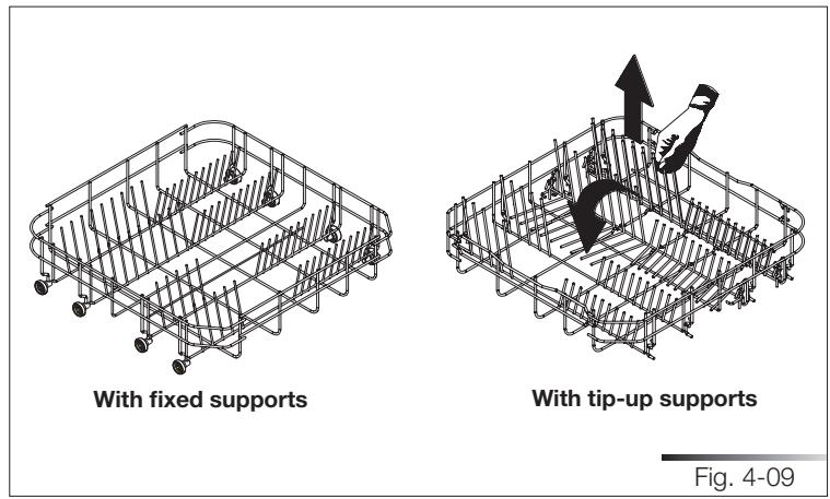
To make the most of the space inside the rack when loading large items, certain models are equipped with tip-up supports for plates in 2 or 4 sections (see fig. 4-09).
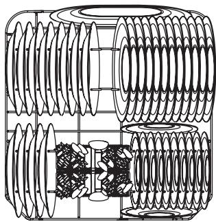
Loading the lower rack (see fig. 4-10)
Carefully load flat plates, soup plates, dessert and serving dishes, positioning them vertically. Pots, pans and their covers must be loaded upside down. When loading soup plates and dessert bowls, be sure to leave a gap between them.
Loading examples:
natural_image
Technical line drawing of a mechanical assembly with coiled spring components (no text or symbols)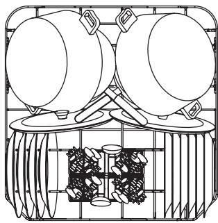
natural_image
Line drawing of a mechanical device with two circular components mounted on a base, surrounded by a grid and four small objects (no text or symbols)1/2 load
(certain models only)
Fig. 4-10
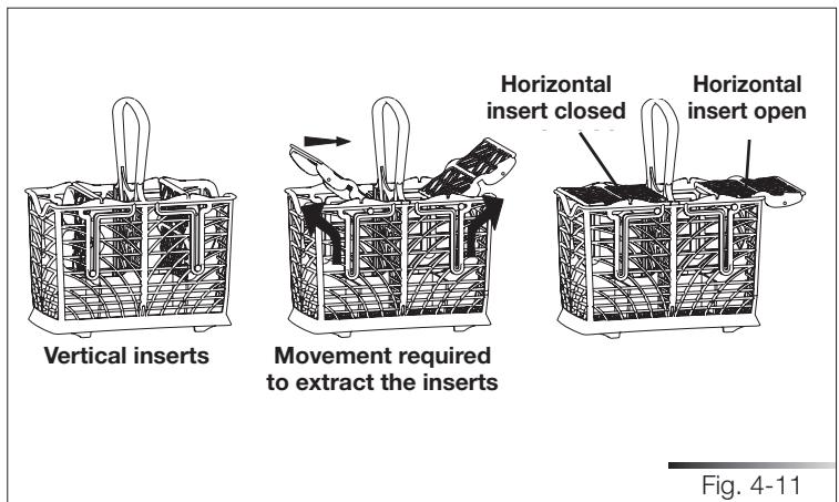
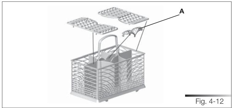
4.4.2 Cutlery basket (see fig. 4-11/4-12 depending on models)
The cutlery basket can be removed to simplify unloading.
Arrange the cutlery in an orderly manner inside the basket, with the handles pointing downwards and taking care not to injure yourself with the knife blades. The basket is suitable for all types of cutlery, except those long enough to interfere with the upper spray arm.
Place long items (ladles, wooden spoons and cooking knives) that may interfere with the spray arm in the upper rack making sure that knife tips do not protrude.
The dishwasher is complete with two cutlery baskets, which means that one of them can be removed, freeing space in the bottom rack, if there is not much cutlery to be washed, or if a 12 load program is being used (on models with this function).
The baskets feature an exclusive system of independent sliding tip-up supports, offering a choice of combinations to allow optimum use of the space available.
text_image
Vertical inserts Movement required to extract the inserts Horizontal insert closed Horizontal insert open Fig. 4-11pla_68xu: The cutlery supports and central lid are in the bag of accessories. The central lid (ref. A fig. 4-12) is intended to act only as a cover; do not place the cutlery in it.
natural_image
3D wireframe model of a basket with internal compartments and labeled parts (A), no text or symbols present4.4.3 Upper rack (see fig. 4-13)
It is recommended to load the upper rack with small- or medium-sized items such as glasses, small plates, tea or coffee cups, shallow bowls and light objects made from heat resistant plastic.
If the upper rack is used in the lowermost position, it can also be loaded with serving dishes, provided they are only slightly soiled.
The top rack is fitted, on the left, with two plastic racks which can be raised to make room for tall glasses, such as stem glasses.

natural_image
Isometric line drawing of a multi-layered mechanical or electrical component with no visible text or symbolsLoading the upper rack (see fig. 4-14)
Load plates facing forward; cups, bowls etc. must always be facing downwards. The left-hand side of the rack can be loaded with two layers of cups and glasses. The centre can be filled with plates and side-plates, fitted upright into the supports provided.
Loading examples:
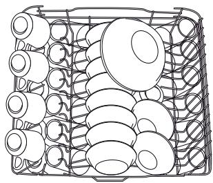
natural_image
Line drawing of a basket filled with various round objects, no text or symbols present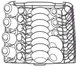
natural_image
Diagram of a container filled with various circular objects, no text or symbols presentFig. 4-14
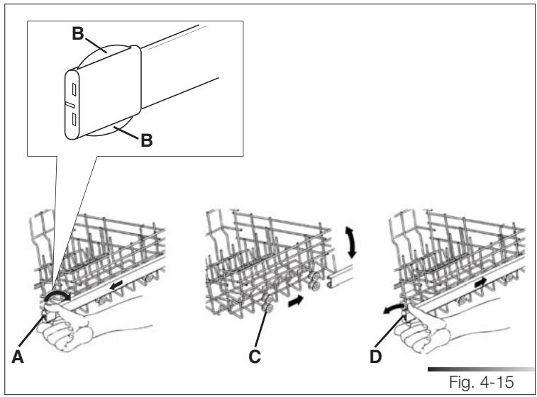
Adjusting the upper rack
Version A (see fig. 4-15): the upper rack can be adjusted in two positions, according to the user's needs and according to the height of the dishes in the lower rack. Proceed as follows:
- pull out the right-hand rack guide. Remove the stop (ref. A fig. 4-15) after releasing the tabs (ref. B fig. 4-15) (first release the upper tab and then the lower one);
- pull out the left-hand rack guide and remove the corresponding stop, just as you did for the right-hand rack guide;
- remove the rack from the guides;
- fit the upper or lower pair of wheels (ref. c fig. 4-15) into the guides, depending on the setting required;
- return the guide stops to their original positions (ref. d fig. 4-15) (first attach the lower tab and then the upper one).
text_image
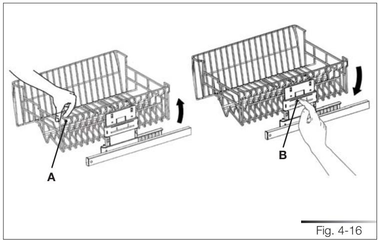
B B A C D Fig. 4-15Version B (see fig. 4-16):
- pull out the rack to its limit position and pull the right side upwards (ref. A fig. 4-16). At this point it is possible to load larger sized plates into the lower rack.
- to return to the original position, pull out the upper rack again and press the release lever (ref. B fig. 4-16).
natural_image
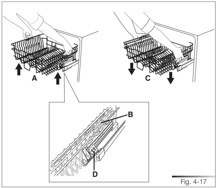
Technical illustration of a structural assembly with labeled components A and B, showing hand positioning and assembly steps (no text or symbols beyond labels)Version C (see fig. 4-17): the upper rack can be set in three different positions on both sides. The rack must be level on both sides.
To raise the rack (ref. A fig. 4-17), lift it with the two handles (e.g.: ref. B fig. 4-17) to the first or second catch depending on the height required. To lower it (ref. c fig. 4-17), pull up the two release levers (e.g.: ref. D fig. 4-17). This is also possible with the rack loaded, but in this case when lowering the rack it should be held steady with one hand to avoid knocking the dishes.
text_image
A C B D Fig. 4-175 CLEANING AND USER-MAINTENANCE

BEFORE CARRYING OUT ANY WORK, ALWAYS DISCONNECT THE APPLIANCE FROM THE ELECTRICAL POWER SUPPLY.
5.1 General warnings and recommendations

NEVER USE ABRASIVE AND/OR CORROSIVE DETERGENTS TO CLEAN THE APPLIANCE.
Clean the outer surfaces and door-lining of the dishwasher regularly using a soft cloth moistened with a neutral detergent (not abrasive and/or corrosive) suitable for painted surfaces. Clean the door gaskets with a damp sponge. Periodically (once or twice a year) it is advisable to clean the tank and gaskets, using a soft cloth and water to remove any deposits.
Do not clean the controls with too much water as this may leak onto the electronic components and damage them.
After cleaning, dry the appliance with a soft, lint-free cloth.
If stainless steel surfaces are preset, clean them with a non-abrasive product specific for stainless steel. To prevent stains, a nebulizer may also be used, though sparingly and at a moderate pressure.
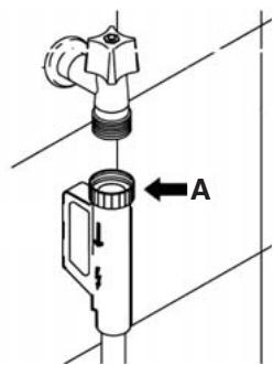
5.2 Cleaning the water intake filter
Clean the water inlet filter at regular intervals. After closing the delivery tap, unscrew the ring nut (ref. A fig. 5-01) on the water inlet pipe (using a pair of pliers, if necessary) and delicately clean the filter, removing deposits or impurities. Then firmly fix the pipe by tightening the ring nut (ref. A fig. 5-01) (use a pair of pliers, if necessary).
text_image
Technical diagram showing a pipe fitting with a valve and directional arrow labeled AFig. 5-01
5.3 Cleaning the spray arms
The spray arms can be easily removed for periodic cleaning of the nozzles, to prevent possible clogging. Wash them under running water (at room temperature) and carefully replace them in their seats, checking that their rotary movement is in no way impeded; if this is not the case, make sure they have been mounted properly.
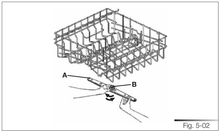
Removing the spray arms
- To remove the upper spray arm (ref. A fig. 5-02), unscrew the locking ring (ref. B fig. 5-02) by turning it clockwise. After cleaning, remount the spray arm in its seat and tighten the locking ring by turning it anti-clockwise.
- To remove the lower spray arm (ref. A fig. 5-03), simply lift it up, pulling by the central part (see fig. 5-03). To remove the orbital spray arm assembly (ref. A fig. 5-04), take hold of the lower arm (ref. B fig. 5-04) and pull the orbital unit upward (see fig. 5-04). After cleaning, remount the orbital spray arm in its seat and push it down slightly until it clicks into place on the lower spray arm (see fig. 5-04). Then remount the lower spray arm into its seat and push it down slightly until it click into place (see fig. 5-03).
natural_image
Technical diagram showing a mechanical assembly with labeled components A and B, and a scale bar indicating Fig. 5-02 (no text or symbols beyond labels)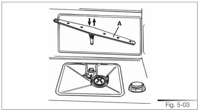
text_image
A Fig. 5-03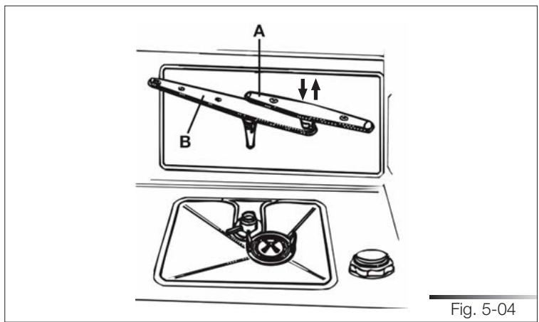
text_image
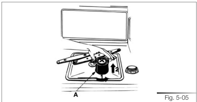
A B Fig. 5-045.4 Cleaning the filter unit
- Periodically inspect the filter unit (ref. A fig. 5-05) and, if necessary, clean it under running water (at room temperature), using a stiff brush. To remove the filter, grip the tabs, turn anticlockwise and lift upwards;
- push the centre filter (ref. A fig. 5-06) from the underside to remove it from the micro-filter;
- separate the two parts which make up the plastic centre filter by pressing the body of the filter in the zone shown by the arrows (ref. B fig. 5-06);
- remove the centre filter by lifting it upwards.
- after cleaning, remount the filter unit, joining the two parts comprising the centre filter by pushing slightly until they click into place; insert the centre filter into the micro-filter (see fig. 5-06). Reposition the filter unit (ref. A fig. 5-05) into its seat, turning it clockwise until it locks.
text_image
Fig. 5-05 A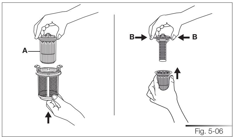
text_image
A B B Fig. 5-065.5 General warnings and recommendations for correct maintenance
- Clean the filters under running water (at room temperature) using a stiff brush.
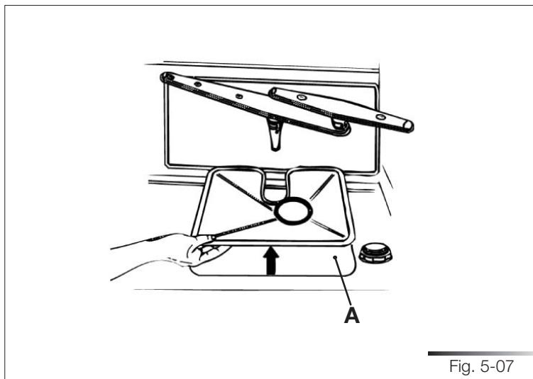
- When removing the filter, take care that there are no food residues on it. If any residues fall into the washing pit (ref. A fig. 5-07), they might block hydraulic components or foul the spray arm nozzles.
- It is essential to thoroughly clean the filters according to the above instructions: the dishwasher cannot function if the filters are clogged.
- Carefully replace the filters in their seats, to avoid damaging the wash pump.
natural_image
Line drawing of a mechanical device with labeled parts A and an arrow, no readable text or symbols beyond labelsProlonged disuse
- Run the soak program twice in succession.
- Unplug the power cord from the socket.
- Leave the door slightly open in order to prevent the formation of unpleasant odors inside the washing tank.
- Fill the rinse-aid dispenser.
- Shut off the water supply tap.
Before starting the dishwasher after prolonged disuse
- Check that there are no deposits of sludge or rust inside the water pipe: if there are, allow the water to run from the water supply tap for a few minutes.
- Plug the power cord back into the socket.
- Reconnect the water intake hose and open the tap again.
5.6 Troubleshooting minor problems
In some cases it is possible to remedy minor problems by referring to the following instructions:
If the program fails to start, check that:
- the dishwasher is connected to the electrical power supply;
• there is no power failure;
• the water tap is open; - the dishwasher door is properly closed.
If water remains inside the dishwasher, check that:
• the drain hose is not kinked
• the drain siphon is not obstructed;
- the dishwasher filters are not clogged.
If the dishes do not come out clean, check that:
- the correct amount of detergent has been added;
- there is regenerating salt inside the special container;
- the dishes are being loaded correctly;
- the selected program is suitable for the dish types and their degree of soil-ing;
- all the filters are clean and positioned correctly;
- the spray arm nozzles are not obstructed;
- there is no object obstructing the rotation of the spray arms.
If the dishes fail to dry or remain dull, check that:
- there is rinse aid inside the special container;
- the rinse-aid dispenser setting is correct;
- the detergent used is of good quality and has not lost its effectiveness (for example, through incorrect storage, with the box left open).
If the dishes show signs of streaking, staining, etc., check that:
- the rinse aid dispenser setting is not too high.
If there are visible traces of rust inside the tank:
- the tank is made of steel, and therefore any rust marks are due to external elements (fragments of rust from the water pipes, pots, cutlery, etc.). Special products are commercially available to remove such marks.
- check that the amount of detergent being used is correct. Certain detergents can be more corrosive than others.
- check that the cap of the salt container is securely closed, and that the water softening setting is correct.

IF AFTER PERFORMING THE ABOVE TROUBLESHOOTING INSTRUCTIONS THE PROBLEM PERSISTS, CALL THE NEAREST TECHNICAL ASSISTANCE CENTRE.
WARNING: ANY OPERATIONS PERFORMED ON THE APPLIANCE BY UNAUTHORIZED PERSONS ARE NOT COVERED BY THE WARRANTY AND SHALL BE PAID FOR BY THE USER.
6 TECHNICAL DATA (SEE TAB. 6-01)
| Width | 59.7 cm ÷ 59.9 cm (23-1/2" ÷ 23-37/64") |
| Depth measured flush with the outer edge of the control panel | 60 cm (23-5/8") - STA861457 cm (22-7/16")-PLA8743;PLA6855 cm (21-21/32")-STA8743 |
| Height | from 86 cm to 91 cm (from 33-55/64" to 35-53/64") |
| Capacity | 12 standard place-settings |
| Water supply pressure | min.7 - max. 130 PSI (min. 0.5 – max. 9 bar) |
| Electrical characteristics | See rating plate |
| Tab. 6-01 | |
Contents
1 INTRODUCTION 3
2 SAFETY INFORMATION 5
3 INSTALLATION MATERIAL 8
3.1 Kit supplied with dishwasher (models sta_4645/sta_8743)....9
3.2 Kit supplied with dishwasher (models pla_8743)....10
4 DIMENSIONS OF DISHWASHER 11
5 INSTALLATION AND HOOK-UP 12
5.1 Leveling....13
5.1.1 Mounting the feet (only for some models).... 13
5.1.2 Levelling the appliance 14
5.2 Connections....15
5.2.1 Connecting to the water supply....16
5.2.1.1 Connecting to the water tap....17
5.2.1.2 Connecting the drain hose....19
5.2.2 Electrical connections and warnings....24
5.3 Commissioning 25
5.3.1 Installation procedure (all models)....26
5.3.2 Procedure for mounting the door panel (models sta_4645/sta_8743).....27
5.3.3 Procedure for mounting the door panel (models pla_8743).... 31
5.3.4 Completion of installation (all models)....35
5.4 Testing 38
1 INTRODUCTION
Thank you for choosing one of our products. To install this dishwasher correctly and safely, please read this manual carefully. The manual is divided into sections giving you a step-by-step guide to installation of the appliance. The texts are easy to understand and are complete with detailed illustrations. This user-friendly manual will provide answers to all your questions about installation of the dishwasher.
This manual comprises the following sections:
INTRODUCTION: general information about the manual.
WARNINGS: a list of warnings concerning safety during installation.
INSTALLATION INSTRUCTIONS: for the qualified technician who must carry out the installation, hook-up and testing of the appliance.
Nomenclature of figures and tables:
The progressive number of each figure is shown in the bottom right-hand corner of the relative box. An example of a progressive number is “Fig. 4-01”, where the first number (4) indicates the section to which the figure belongs, while the second number (01) indicates the progressive number of the figure in section 4 (Fig. 4-01 is the first figure in section 4). The tables are numbered in the same way, bearing in mind that “Tab.” is used instead of “Fig.” (e.g.: Tab. 4-01 is the first table in section 4). If a table occupies more than one page, a letter is added after the progressive number (e.g.: “Tab. 4-01a”, Tab. 4-01b”).
Symbols used in this manual (see tab. 1-01)
 | DANGER. This symbol highlights information and warnings which, if not observed, may compromise personal safety or damage the appliance. |
 | DANGER OF ELECTROCUTION. This symbol highlights information and warnings of an electrical nature which, if not observed, may compromise personal safety or damage the appliance. |
 | This symbol highlights general information and warnings. |
| Tab. 1-01 | |
2 SAFETY INFORMATION

THIS MANUAL FORMS AN INTEGRAL PART OF THE APPLIANCE AND MUST THEREFORE BE KEPT INTACT TOGETHER WITH THE MACHINE. BEFORE USING THE APPLIANCE, CAREFULLY READ ALL THE INSTRUCTIONS CONTAINED IN THIS MANUAL. INSTALLATION MUST BE PERFORMED BY A QUALIFIED TECHNICIAN, IN COMPLIANCE WITH THE REGULATIONS IN FORCE. THIS APPLIANCE IS INTENDED FOR DOMESTIC USE, AND COMPLIES WITH THE DIRECTIVES CURRENTLY IN FORCE, INCLUDING THE PREVENTION AND ELIMINATION OF RADIO FREQUENCY INTERFERENCE. THE APPLIANCE IS DESIGNED FOR THE FOLLOWING PURPOSE: WASHING AND DRYING OF DISHES; ANY OTHER USE SHALL BE CONSIDERED IMPROPER. THE MANUFACTURER DECLINES ALL RESPONSIBILITY FOR USES OTHER THAN THOSE DESCRIBED ABOVE.

INSTALLATION, REPAIRS AND SERVICING MUST BE PERFORMED BY QUALIFIED AND AUTHORIZED TECHNICIANS. AS WELL AS INVALIDATING THE WARRANTY, WORK CARRIED OUT BY UNAUTHORIZED PERSONS MAY GENERATE HAZARDS. INSTALLATION MUST BE PERFORMED IN COMPLIANCE WITH ALL THE DIRECTIVES IN FORCE IN THE COUNTRY OF INSTALLATION AND, IF THESE DO NOT EXIST: IN THE UNITED STATES THE NATIONAL ELECTRIC CODE; IN CANADA THE CANADIAN ELECTRIC CODE C22.1 - LATEST EDITION/PROVINCIAL AND MUNICIPAL CODES AND/OR LOCAL CODES.

THE NAME PLATE FEATURING THE TECHNICAL DATA, SERIAL NUMBER AND MARKINGS IS VISIBLY POSITIONED ON THE INNER EDGE OF THE DOOR. THE NAMEPLATE ON THE INNER EDGE OF THE DOOR MUST NEVER BE REMOVED.

THIS APPLIANCE IS NOT SUITABLE FOR USE ON BOATS, CARAVANS OR THE LIKE. DISHWASHERS CERTIFIED FOR DOMESTIC USE ARE NOT SUITABLE FOR AUTHORISED FOOD FACTORIES.

CHECK THAT THE VOLTAGE, FREQUENCY AND PROTECTION OF THE DOMESTIC MAINS POWER SUPPLY MATCH THE RATINGS ON THE NAME PLATE OF THE APPLIANCE.

TWO PEOPLE WEARING SAFETY GLOVES ARE REQUIRED TO LIFT THE DISHWASHER.

DO NOT LEAVING DISCARDED PACKAGING MATERIALS UNSUPERVISED WITHIN THE HOME. SEPARATE THE VARIOUS PACKAGING MATERIALS AND TAKE THEM TO THE NEAREST SORTED WASTE COLLECTION CENTRE. KEEP CHILDREN, PHYSICALLY AND/OR MENTALLY IMPAIRED ADULTS, AND ANIMALS AWAY FROM PACKAGING WASTE; DANGER OF SUFFOCATION.

BEFORE PROCEEDING WITH INSTALLATION, DISCONNECT THE MAINS POWER SUPPLY FROM THE WORK AREA.

DURING INSTALLATION, TAKE CARE NOT TO INJURE YOURSELF ON THE SHARP EDGES OF THE APPLIANCE; WEAR SAFETY GLOVES.

THE APPLIANCE MUST BE PROVIDED WITH A GROUND CONNECTION IN ACCORDANCE WITH THE ELECTRICAL SAFETY REGULATIONS IN FORCE. IF IN DOUBT, HAVE THE SYSTEM CHECKED BY A QUALIFIED ELECTRICIAN.
THE MANUFACTURER DECLINES ALL RESPONSIBILITY FOR DAMAGE TO PERSONS OR PROPERTY RESULTING FROM THE FAILURE TO GROUND THE APPLIANCE OR FROM A DEFECTIVE GROUND CONNECTION.

DO NOT USE APPLIANCES WHICH HAVE BEEN DAMAGED DURING TRANSIT! IF IN DOUBT, CONSULT YOUR DEALER. THE APPLIANCE MUST BE INSTALLED AND CONNECTED IN ACCORDANCE WITH THE INSTRUCTIONS PROVIDED BY THE MANUFACTURER OR BY A QUALIFIED TECHNICIAN.

DO NOT OPERATE THE DISHWASHER UNLESS ALL THE OUTER PANELS HAVE BEEN POSITIONED CORRECTLY.
IMMEDIATELY AFTER INSTALLATION, BRIEFLY TEST THE APPLIANCE FOLLOWING THE INSTRUCTIONS INDICATED BELOW. IF THE DISHWASHER FAILS TO OPERATE CORRECTLY, DISCONNECT IT FROM THE ELECTRICAL POWER SUPPLY AND CALL THE NEAREST TECHNICAL SERVICE CENTRE. DO NOT ATTEMPT TO REPAIR THE APPLIANCE.

DO NOT USE EXTENSION CORDS, ADAPTORS OR SHUNT CONNECTIONS IN ORDER TO AVOID THE POSSIBILITY OF OVERHEATING OR BURNING, WITH CONSEQUENT FIRE HAZARD.

THE MANUFACTURER DECLINES ALL RESPONSIBILITY FOR DAMAGE TO PERSONS, ANIMALS OR PROPERTY RESULTING FROM FAILURE TO OBSERVE THE ABOVE PRECAUTIONS, FROM TAMPERING WITH EVEN A SINGLE COMPONENT OF THE APPLIANCE, OR FROM THE USE OF UNORIGINAL SPARE PARTS.
IF IN DOUBT ABOUT THE CONTENTS OF THIS MANUAL, CONTACT THE TECHNICAL ASSISTANCE SERVICE.
3 INSTALLATION MATERIAL
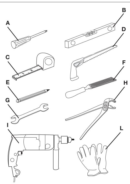
To install the dishwasher correctly, the following materials are required:
• Phillips screwdriver (ref. A fig. 3-01);
• spirit level (ref. B fig. 3-01);
- tape measure (ref. C fig. 3-01);
- compass saw (ref. D fig. 3-01);
- pencil (ref. E fig. 3-01);
- file (ref. F fig. 3-01);
• 13 mm open-ended wrench (ref. G fig. 3-01);
- plumbing pliers (ref. H fig. 3-01);
- drill (ref. I fig. 3-01);
• safety gloves (ref. L fig. 3-01).
text_image
A B C D E F G H I LFig. 3-01
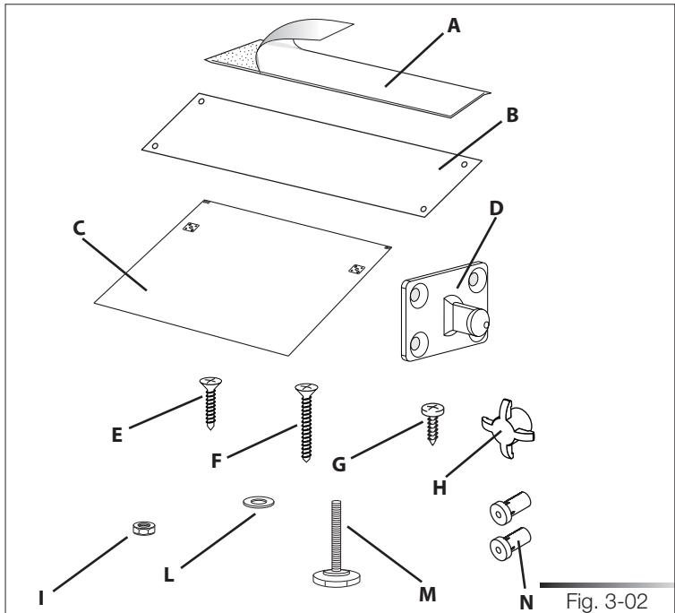
3.1 Kit supplied with dishwasher (models sta\_4645/sta\_8743)
The kit supplied with the dishwasher comprises:
• adhesive steam guard (ref. A fig. 3-02);
• 1 steel steam guard (ref. B fig. 3-02);*
• 1 template for door panel (ref. C fig. 3-02);
• 2 hooks for door panel (ref. D fig. 3-02);
- 8 screws for securing the door panel hooks (ref. E fig. 3-02);
• 2 screws for securing the door (ref. F fig. 3-02);
- 2 screws for fixing the dishwasher to the adjacent walls (ref. G fig. 3-02);
• 2 screw caps (ref. H fig. 3-02).
• 2 nuts (only for some models) (ref. I fig. 3-02);
• 2 washers (only for some models) (ref. L fig. 3-02);
• 2 adjustment feet (only for some models) (ref. M fig. 3-02);
- 2 door spacers (only for certain models) (ref. N fig. 3-02).
text_image
A B C D E F G H I L M N Fig. 3-02* The adhesive protection is suitable for kitchens with worktops that do not allow the steel protection to be fixed with screws (e.g.: + marble or masonry), but it can be also used with other materials.
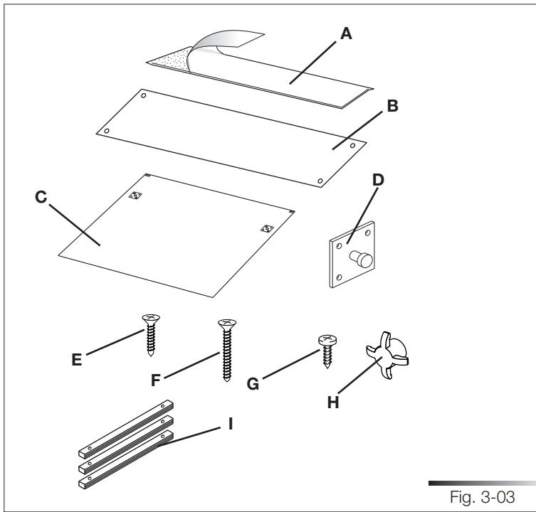
3.2 Kit supplied with dishwasher (models pla\_8743)
The kit supplied with the dishwasher comprises:
• adhesive steam guard (ref. A fig. 3-03);
• 1 steel steam guard (ref. B fig. 3-03);*
• 1 template for door panel (ref. C fig. 3-03);
• 2 hooks for door panel (ref. D fig. 3-03);
- 8 screws for securing the door panel hooks (ref. E fig. 3-03);
- 2 screws for securing the door (ref. F fig. 3-03);
- 2 screws for fixing the dishwasher to the adjacent walls (ref. G fig. 3-03);
• 2 screw caps (ref. H fig. 3-03).
• 3 compensation strips (ref. I fig. 3-03).
text_image
A B C D E F G H I Fig. 3-03* The adhesive protection is suitable for kitchens with worktops that do not allow the steel protection to be fixed with screws (e.g.: + marble or masonry), but it can be also used with other materials.
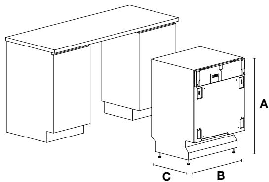
4 DIMENSIONS OF DISHWASHER (See fig. 4-01)
| Model | A (height) | B (width) | C (depth) |
| STA8743 | 86 cm ÷ 91 cm33-55/64" ÷ 35-55/64" | 59.7 cm ÷ 59,9 cm23-1/2" ÷ 23-37/64" | 55 cm21-21/32" |
| STA8614X | 86 cm ÷ 91 cm33-55/64" ÷ 35-55/64" | 59.7 cm ÷ 59.9 cm23-1/2" ÷ 23-37/64" | 60 cm23-5/8" |
| STA4645 | 82 cm ÷ 87 cm32-9/32" ÷ 34-1/4" | 44.7 cm ÷ 44.9 cm17-19/32" ÷ 17-43/64" | 55 cm21-21/32" |
| PLA8743X | 86 cm ÷ 91 cm33-55/64" ÷ 35-55/64" | 59.7 cm ÷ 59.9 cm23-1/2" ÷ 23-37/64" | 57 cm22-7/16" |
| PLA68XU | 86 cm ÷ 91 cm33-55/64" ÷ 35-55/64" | 59.7 cm ÷ 59.9 cm23-1/2" ÷ 23-37/64" | 60 cm23-5/8" |
| Tab. 4-01 | |||
natural_image
Technical line drawing of a two-story office setup with labeled dimensions A, B, and C (no text or symbols beyond labels)Fig. 4-01
5 INSTALLATION AND HOOK-UP

DURING INSTALLATION, TAKE CARE NOT TO INJURE YOURSELF ON THE SHARP EDGES OF THE APPLIANCE.
Remove the polystyrene rack blocks. Position the appliance in the chosen installation position. The sides and rear of the appliance can lie against kitchen units or walls. If the dishwasher is installed next to a heat source, separate it with a heat insulating panel in order to prevent overheating and malfunctions. To assure stability, only install built-in appliances under continuous worktops, securing them to the adjacent kitchen units or worktop with screws.

BUILDING-IN A DISHWASHER UNDERNEATH A CERAMIC HOB IS ABSOLUTELY FORBIDDEN. A DISHWASHER CAN BE BUILT-IN UNDERNEATH A CONVENTIONAL HOB PROVIDED THERE IS NO BREAK IN THE KITCHEN WORKTOP, AND THE DISHWASHER AND HOB ARE INSTALLED AND SECURED CORRECTLY, SO THAT NO HAZARDS ARE GENERATED.

MAKE SURE THE DISHWASHER HAS BEEN CORRECTLY INSTALLED AND GROUNDED BY A QUALIFIED FITTER. THIS SAFETY REQUIREMENT MUST BE MET. IN CASE OF DOUBT, CALL IN A QUALIFIED FITTER. THE MANUFACTURER DECLINES ALL RESPONSIBILITY FOR DAMAGE TO PERSONS OR PROPERTY RESULTING FROM THE FAILURE TO GROUND THE APPLIANCE OR FROM A DEFECTIVE GROUND CONNECTION.

BEFORE PROCEEDING WITH INSTALLATION, DISCONNECT THE MAINS POWER SUPPLY FROM THE WORK AREA.
Only for free-standing models
- It is strictly forbidden to mount a hob over a free-standing dishwasher.
- If the appliance is not in a niche and can therefore be accessed on one side, cover the door hinge area for safety reasons (cutting hazard). Covers are available as accessories from specialized retailers or from the Technical Service Centre.
- To build in the dishwasher, purchase the relative kit from specialized retailers or from the Technical Service Centre.
5.1 Leveling
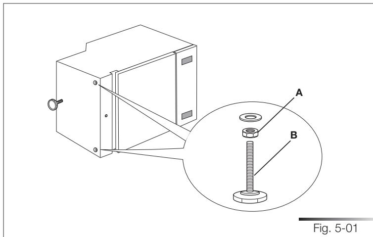
5.1.1 Mounting the feet (only for some models)
Turn the appliance upside-down (see fig. 5-01).
Tighten the nut (see ref. A fig. 5-01) onto the threaded pin (see ref. B fig. 5-01) of the foot and then fit the supplied washer; do this on both feet.
Screw the feet onto the appliance until the washers touch the base; the two feet must be manually adjusted to the same height to prevent excessive differences in height between one foot and the other.
Put the appliance back on its feet.

TWO PEOPLE WEARING SAFETY GLOVES ARE NEEDED TO TURN THE DISHWASHER UPSIDE-DOWN.
text_image
A B Fig. 5-015.1.2 Levelling the appliance
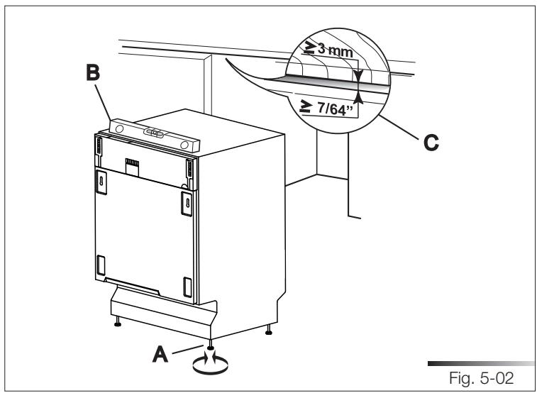
Level the appliance using the relative adjustable feet (e.g.: ref. A fig. 5-02); use an open-ended wrench to rotate the feet until the dishwasher is perfectly level.
Some models are fitted with just one rear foot which can be adjusted with a screw located at the bottom front of the appliance (ref. A fig. 5-03); use a suitable Phillips screwdriver to turn the screw until the dishwasher is perfectly level.
Use a spirit level to check the appliance is perfectly level (ref. B fig. 5-02).
Leveling is vital for assuring correct dishwasher operation.
Make sure to leave a gap of at least 3 mm (7/64") between the top of the dishwasher and the worktop (ref. C fig. 5-02).
text_image
B ≥3 mm ≥ 7/64" C A Fig. 5-02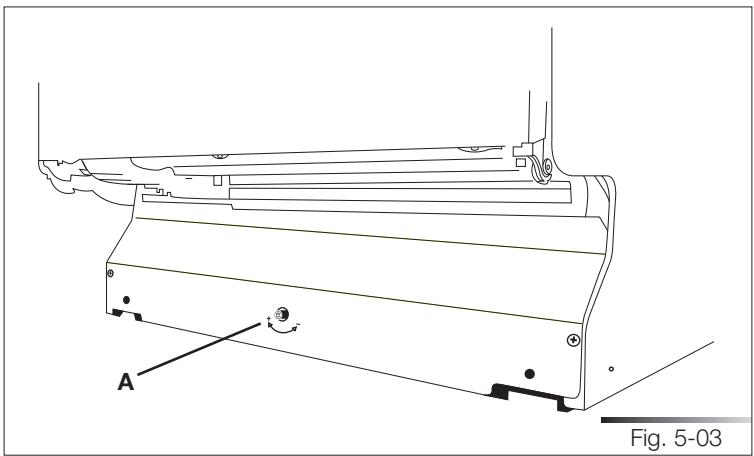
natural_image
Technical line drawing of a mechanical component with labeled parts and angle marker (no readable text or symbols)5.2 Connections
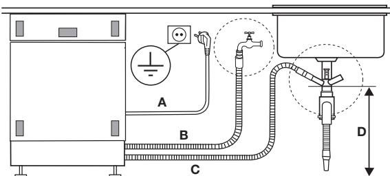
Install the dishwasher so as to allow ease of access to the electrical and hydraulic connections through the adjacent unit. These connections must never be behind the dishwasher.
The inlet and drain hoses can be pointed in all directions. make sure that they are not bent, crushed or too tight. Tighten the ring nut after pointing the hoses in the required direction.
Figure 5-04 indicates the distances to maintain between the dishwasher and the various connections.

FIRE HAZARD!
DO NOT COVER OR CRUSH THE CORD PLUG.
text_image
A B C DA = ∼1200 mm / 47"
B = ∼ 1500 mm / 59"
C = \~1600 mm / 63"
D = min. 400 mm / 16"
Fig. 5-04
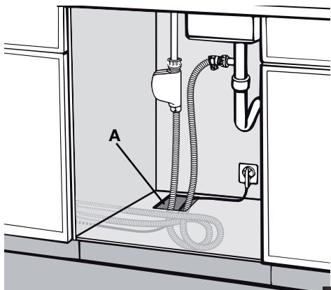
A through hole with a diameter of at least 8 cm (5/32") is required to pass the hoses and power cord (ref. A fig. 5-05).
Make sure there area no rough edges that could damage the power cord or hoses. If the dishwasher is installed in a metal unit protect the edge of the through hole for the hoses and power cord with a gasket. Do not use extension cords when making the electrical connection as these do not guarantee safety.

ATTENTION!
INSTALLING THE DISHWASHER IN A NARROW SPACE MAY BEND OR CRUSH THE POWER CORD. TAKE GREAT CARE IN ORDER TO REDUCE THE POSSIBILITY OF DAMAGING THE POWER CORD WHEN INSTALLING OR REMOVING THE APPLIANCE.
natural_image
Interior view of a kitchen sink with pipes and fixtures (no text or symbols)Fig. 5-05
5.2.1 Connecting to the water supply

PREVENTING THE RISK OF CLOGGING OR DAMAGE: IF THE WATER PIPE IS NEW OR HAS NOT BEEN USED FOR A LONG TIME, BEFORE CONNECTING TO THE WATER SUPPLY CHECK THAT THE WATER IS CLEAR AND FREE OF IMPURITIES, TO PREVENT DAMAGE TO THE APPLIANCE. THE DISHWASHER MUST ALWAYS BE CONNECTED TO THE WATER SYSTEM WITH NEW HOSES; OLD OR USED HOSES MUST NEVER BE REUSED.
5.2.1.1 Connecting to the water tap
Connect the inlet hose to a threaded 34 " gas cold water tap, fitting the supplied filter (ref. A fig. 5-06). Firmly secure the hose by tightening the relative ring nut with your hands (ref. B fig. 5-06); finish by tightening another 14 turn using a pair of plumbing pliers. For models fitted with ACQUASTOP (ref. C fig. 5-06) the filter is already present in the threaded ring nut.
The dishwasher can be filled with water at a temperature of less than 60^ C ( 140^ F).
If the appliance is filled with hot water, washing times will be reduced by about 20 minutes, but efficiency will be slightly impaired. Make the connection to the domestic hot water tap using the same methods described for connecting the appliance to the cold water tap.
- Recommended temperature: 49^ (120°F), max. 60^ (140°F).
- Recommended water pressure: 0.5 - 9 bar (7 -130 PSI).
If the pressure is too high, fit a pressure reducer.
A rubber hose connected to a sink spray may burst if installed on the same pipes feeding the dishwasher. If your sink is fitted with this accessory, remove the hose and plug the hole.
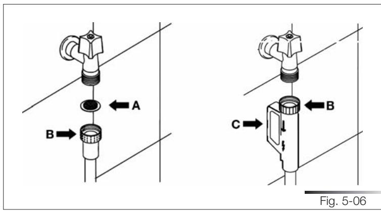
text_image
A B C Fig. 5-06Do not cut the inlet hose (see fig. 5-07).
If the hose is cut, the dishwasher will not work, water will leak and you may be injured.
If the hose is too long, wind it up tidily and place it behind the appliance.
The cable harness and electrical components must not come into contact with the hydraulic system and the water inlet and drain hoses.
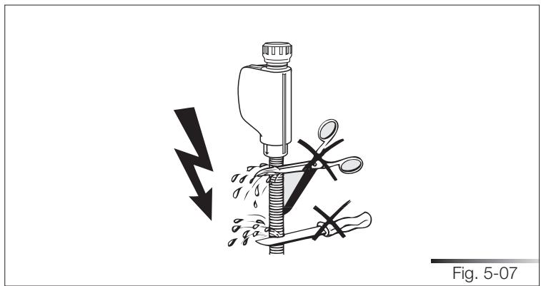
natural_image
Diagram of a mechanical device with forceps and a lightning bolt, showing no text or symbolsWhen connecting the dishwasher drain hose to the sink make sure that the hose is not bent (ref. A fig. 5-08) in order to prevent cracks or breakages that could damage it.
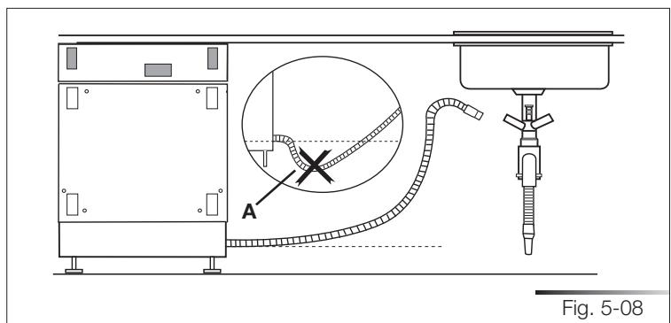
text_image
Fig. 5-085.2.1.2 Connecting the drain hose
Connecting to a drain
Insert the relative hose into a drain with a minimum diameter of 4 cm (1-37/64") (ref. A fig. 5-09); alternatively, place the hose on the sink (ref. B fig. 5-09) using the supplied hose support (see fig. 5-10), but taking care to avoid obstructions or excessive curving. Make sure the hose cannot fall out. For this purpose, the hose support is fitted with a hole (ref. A fig. 5-10) which can be used to fix it to the wall or the tap with a piece of string. The free end must lie at a height ranging from of 30 to 100 cm (from of 1-7/32" to 3-59/64") (see fig. 5-09) and must never be immersed in water. If horizontal extension hoses with a maximum length of 3m are used, position the drain hose at a maximum height of 85 cm (3-11/32") above the floor.
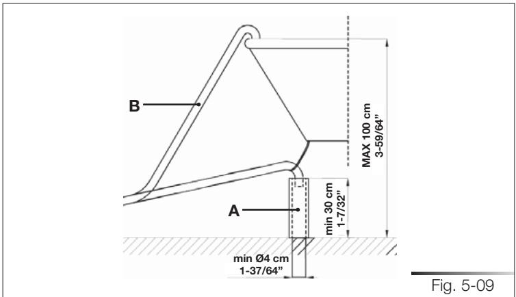
text_image
B MAX 100 cm 3-59/64" A min 30 cm 1-7/32" min Ø4 cm 1-37/64" Fig. 5-09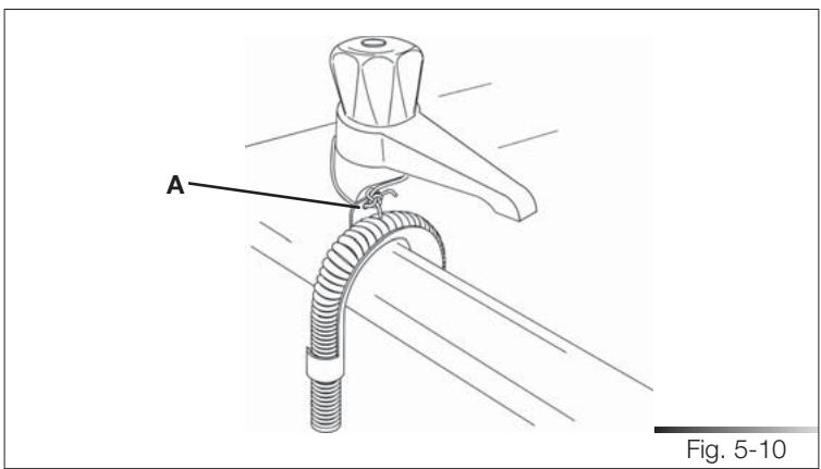
text_image
A Fig. 5-10Connecting to a "T" union of the drain circuit

MAKE THE CONNECTION UPLINE FROM THE SIPHON OF THE DRAIN LINE AND AT LEAST 400 mm (15-3/4") ABOVE THE FLOOR ON WHICH THE DISHWASHER WILL BE INSTALLED.
- Connect the dishwasher drain hose (ref. A fig. 5-11) to the "T" union (ref. B fig. 5-11) of the drain circuit using a 38 to 50mm (1-1/2 to 2") screw clamp* (ref. C fig. 5-11); if necessary, cut the end of the dishwasher drain hose (ref. D fig. 5-11) (do not cut the corrugated section).
* Available from any plumbing stockist
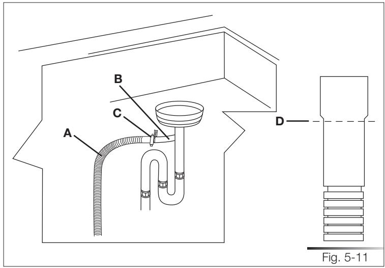
text_image
A B C D Fig. 5-11Connecting to a waste disposal unit with an air gap

MAKE THE CONNECTION UPLINE FROM THE SIPHON OF THE DRAIN LINE AND AT LEAST 400 mm (15-3/4") ABOVE THE FLOOR ON WHICH THE DISHWASHER WILL BE INSTALLED.
- Remove the cover of the waste disposal unit (ref. A fig. 5-12).
- Connect the dishwasher drain hose (ref. B fig. 5-12) to the air gap (ref. C fig. 5-12) using the wide spring clamp (ref. D fig. 5-12); if necessary, cut the end of the dishwasher drain hose (ref. E fig. 5-12) (do not cut the corrugated section). If the drain hose has been cut, use a 38 to 50 mm (1-1/2 to 2") screw clamp*.
- To connect the air gap (ref. C fig. 5-12) to the waste disposal unit inlet (ref. F fig. 5-12), use a rubber union* (ref. G fig. 5-12) with spring or screw clamps* (ref. H fig. 5-12).
* Available from any plumbing stockist
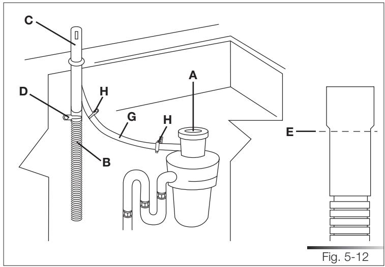
text_image
C D H G A B H E Fig. 5-12Connecting to the air gap (no waste disposal unit)

MAKE THE CONNECTION UPLINE FROM THE SIPHON OF THE DRAIN LINE AND AT LEAST 400 mm (15-3/4") ABOVE THE FLOOR ON WHICH THE DISHWASHER WILL BE INSTALLED.
- Connect the dishwasher drain hose (ref. A fig. 5-13) to the air gap (ref. B fig. 5-13) using the wide spring clamp (ref. C fig. 5-13); if necessary, cut the end of the dishwasher drain hose (ref. D fig. 5-13) (do not cut the corrugated section). If the drain hose has been cut, use a 38 to 50 mm (1-1/2 to 2") screw clamp*.
- To connect the air gap (ref. B fig. 5-13) to the "T" union (ref. E fig. 5-13) of the drain line, use a rubber union* (ref. F fig. 5-13) with spring or screw clamps* (ref. G fig. 5-13).
* Available from any plumbing stockist
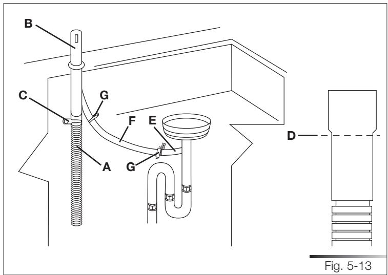
text_image
B C G F E A G D Fig. 5-13Connecting to a waste disposal unit (no air gap)

MAKE THE CONNECTION UPLINE FROM THE SIPHON OF THE DRAIN LINE AND AT LEAST 400 mm (15-3/4") ABOVE THE FLOOR ON WHICH THE DISHWASHER WILL BE INSTALLED.
- Remove the cover of the waste disposal unit (ref. A fig. 5-14).
- Connect the dishwasher drain hose (ref. B fig. 5-14) to the waste disposal unit inlet (ref. C fig. 5-14), using the wide spring clamp (ref. D fig. 5-14).
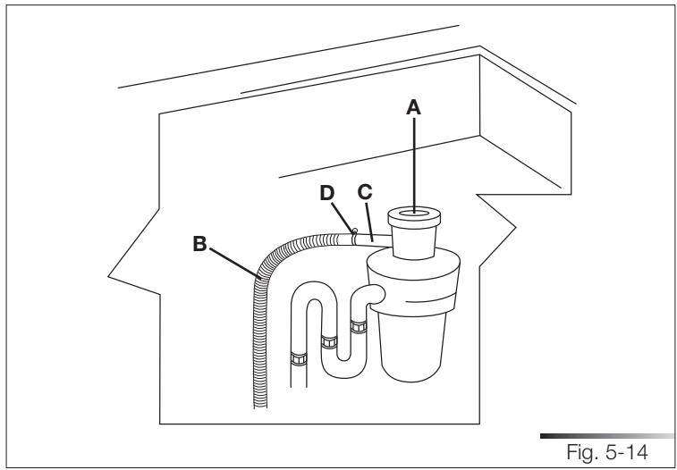
text_image
A D C B Fig. 5-145.2.2 Electrical connections and warnings

CHECK THAT THE VOLTAGE AND THE FREQUENCY OF THE MAINS MATCH THE RATINGS ON THE NAME PLATE OF THE APPLIANCE POSITIONED ON THE INNER EDGE OF THE DOOR.

IN THE EVENT OF DAMAGE TO THE SUPPLY CORD, HAVE IT REPLACED BY THE MANUFACTURER OR AN AUTHORIZED TECHNICAL SERVICE CENTRE.
THIS APPLIANCE MUST BE GROUNDED. IN CASE OF A MAL-FUNCTION OF FAULT, THE GROUND REDUCES THE RISK OF ELECTROCUTION BY PROVIDING THE ELECTRICAL CURRENT WITH AN ALTERNATIVE, LESS RESISTANT PATH.

THIS APPLIANCE MUST BE GROUNDED. IN CASE OF A MALFUNCTION OF FAULT, THE GROUND REDUCES THE RISK OF ELECTROCUTION BY PROVIDING THE ELECTRICAL CURRENT WITH AN ALTERNATIVE, LESS RESISTANT PATH. THIS APPLIANCE IS FITTED WITH A SUPPLY CORD CONTAINING A GROUND WIRE AND PLUG. FIT THE PLUG INTO A SUITABLE SOCKET, INSTALLED AND GROUNDED IN COMPLIANCE WITH THE LAWS IN FORCE IN THE COUNTRY OF INSTALLATION.

BEFORE MAKING ELECTRICAL CONNECTIONS, DISCONNECT THE MAINS POWER SUPPLY FROM THE WORK AREA.
Grounding instructions
This appliance is fitted with a cord with ground wire and plug. Fit the plug into a suitable socket, installed and grounded in compliance with the laws in force in the country of installation.

CHECK THAT THE MAINS SUPPLY IN THE PLACE OF INSTALLATION COMPLIES WITH THE REGULATIONS IN FORCE IN THE COUNTRY OF USE, AND THAT IT IS CORRECTLY GROUNDED.

AN INCORRECTLY CONNECTED GROUND WIRE MAY GENERATE THE RISK OF ELECTROCUTION. IF IN DOUBT AS TO THE CORRECT GROUNDING OF THE APPLIANCE, CALL IN A QUALIFIED ELECTRICIAN OR THE TECHNICAL ASSISTANCE SERVICE. DO NOT CHANGE THE PLUG ATTACHED TO THE APPLIANCE. IF THE
PLUG IS NOT SUITABLE FOR THE SOCKET, CALL IN A QUALIFIED ELECTRICIAN TO FIT A SUITABLE PLUG.
The plug at the end of the power cord and the corresponding socket must be of the same type and must conform to current regulations governing electrical appliances. The plug must be accessible after installation. Never remove the plug by pulling on the wire. If the power cord is damaged, have it replaced by the manufacturer or an authorized service centre.

DO NOT USE EXTENSION CORDS, ADAPTORS OR SHUNT CONNECTIONS IN ORDER TO AVOID THE POSSIBILITY OF OVERHEATING OR BURNING, WITH CONSEQUENT FIRE HAZARD.

IN THE EVENT OF DAMAGE TO THE SUPPLY CORD, HAVE IT REPLACED BY THE MANUFACTURER OR AN AUTHORIZED TECHNICAL SERVICE CENTRE IN ORDER TO AVOID ANY RISK.
5.3 Commissioning
5.3.1 Installation procedure (all models)
Clean the underneath of the worktop lying over the dishwasher door (see fig. 5-15) and apply the steam guard, as shown in fig. 5-16 (see fig. 5-16 if the adhesive guard is applied; see fig. 5-17 if the steel guard is applied). This guard protects the worktop from steam and condensation when the door of the dishwasher is opened at the end of the washing cycle.
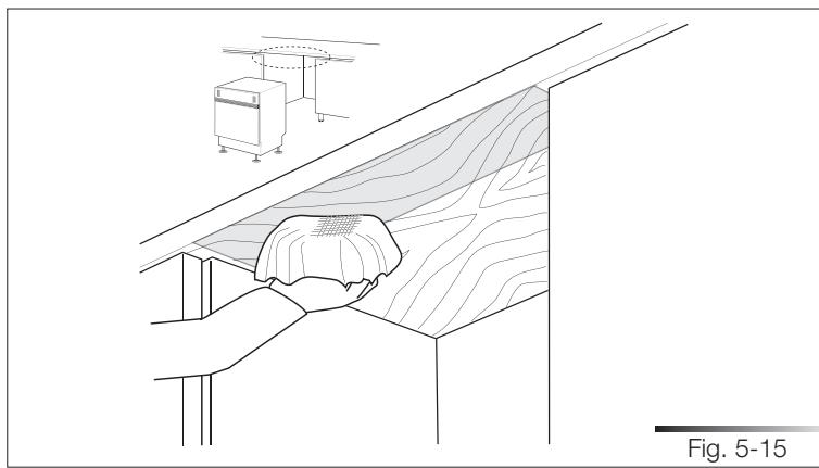
natural_image
Architectural or engineering diagram showing a person working on a sloped surface with a cabinet and equipment in the background (no text or symbols)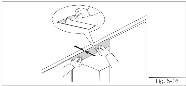
text_image
Fig. 5-16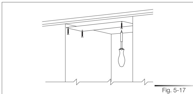
natural_image
Technical line drawing of a mechanical support structure with no visible text or symbolsPush the dishwasher into position, taking care not to twist or crush the power cord or hoses (see fig. 5-18).

TWO PEOPLE WEARING SAFETY GLOVES ARE NEEDED TO PUSH THE DISHWASHER INTO PLACE.
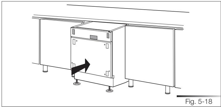
natural_image
Technical line drawing of a cabinet or enclosure with mounting feet and a directional arrow indicating movement (no text or symbols)5.3.2 Procedure for mounting the door panel (models sta\_4645/sta\_8743)
Mount the door panel.
Place the template on the inner surface of the panel, centering it along the upper side and matching up the reference locators (ref. A fig. 5-19); mark the position of the door hooks with a pencil (see fig. 5-19). Remove the template and use a drill with a suitable bit to make holes at the points marked on the panel.
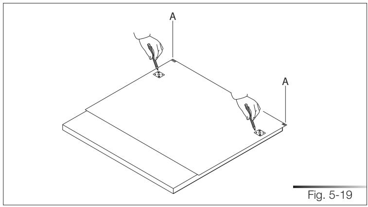
natural_image
Isometric line drawing of a flatboard with two hands holding probes, labeled 'A', and a scale bar indicating Fig. 5-19 (no text or symbols on the diagram itself)Use the screwdriver to secure the door hooks with the 8 supplied screws (see fig. 5-20) at the marked reference points.
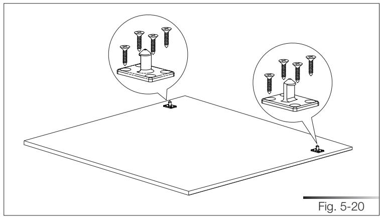
natural_image
Technical illustration of a screw installation with two views showing bolt holes and mounting base (no text or symbols)Drill holes for the panel handle using a drill with a suitable bit. Use the screw-driver to secure the door handle before hooking the panel to the dishwasher (see fig. 5-21).
N.B.: the screws are not supplied.
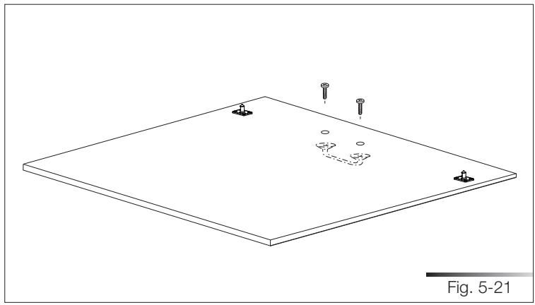
natural_image
Isometric line drawing of a flat plate with four small screws and a dashed-line feature, labeled Fig. 5-21 (no text or symbols on the diagram itself)Insert the door spacers contained in the accessory bag (see fig. 5-22).
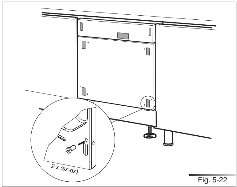
text_image
2 x (sx-dx) Fig. 5-22Attach the door panel: fit the hooks into their slots on the dishwasher and allow the panel to slide downwards and slip in to place (see fig. 5-23).
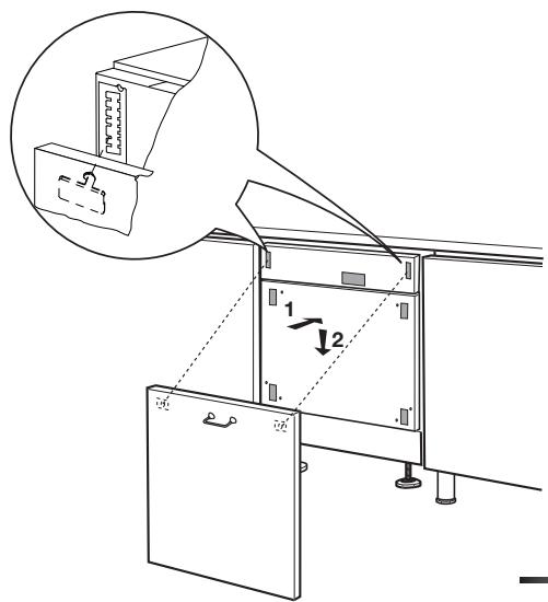
text_image
Technical diagram showing a mechanical assembly with labeled components and an inset magnified view of a device component.Fig. 5-23
Secure the door to the panel with the supplied screws. The panel must have a minimum thickness of 20 mm (25/32") (see fig. 5-24).

natural_image
Technical line drawing of a mechanical testing setup with a tool and rotating component (no text or symbols)Fig. 5-24
Make sure the dishwasher door, complete with panel, opens comfortably and that the base plate (ref. A fig. 5-25) does not prevent it from opening fully. If the base plate prevents the door from opening, mark out the section to remove (see fig. 5-25), take out the base plate and cut it along the marking using a compass saw (see fig. 5-26).
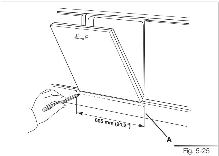
text_image
605 mm (24.2") A Fig. 5-25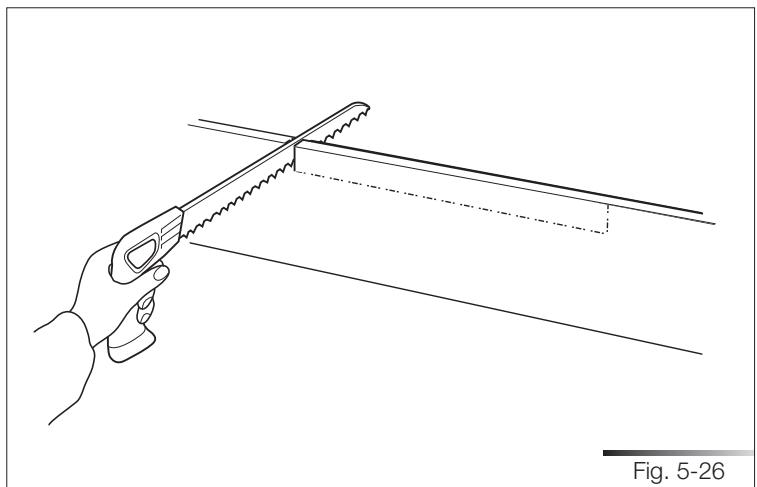
natural_image
Line drawing of a hand using a saw to cut a diagonal line, labeled as Fig. 5-26 (no text or symbols on the diagram itself)5.3.3 Procedure for mounting the door panel (models pla\_8743)
Mount the door panel.
Place the template on the inner surface of the panel, centering it along the upper side and matching up the reference locators (ref. A fig. 5-27); mark the position of the door hooks with a pencil (see fig. 5-27). Remove the template and use a drill with a suitable bit to make holes at the points marked on the panel.
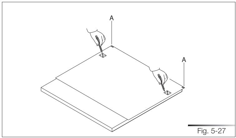
natural_image
Isometric line drawing of a flatboard with two hands holding pens, labeled 'A', and a scale bar indicating Fig. 5-27 (no text or symbols on the diagram itself)Use the screwdriver to secure the door hooks with the 8 supplied screws (see fig. 5-28) at the marked reference points.
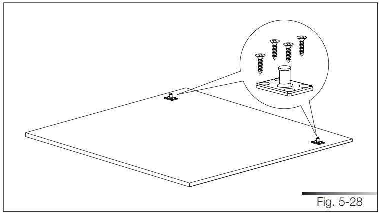
natural_image
Technical line drawing of a flat plate with screw holes and an inset showing a bolt assembly (no text or symbols)If a gap is created between the control panel and the door panel (ref. A fig. 5-29), use the supplied strips (ref. B fig. 5-29) to fill it. The number of strips depends on the size of the gap.
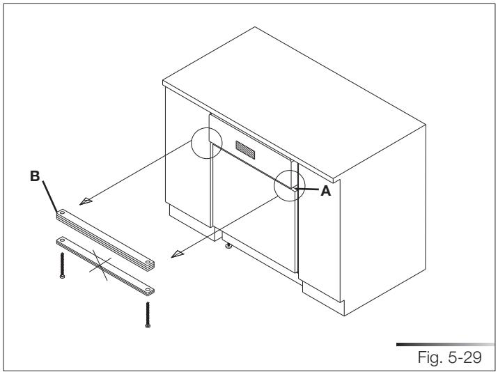
text_image
B A Fig. 5-29Position the strips between the control panel and the door panel of the dishwasher (ref. A fig 5-30) and fix them from under the control panel with the supplied screws (ref. B fig. 5-30) using a screwdriver. Adjust the strips until a suitable compromise is reached.
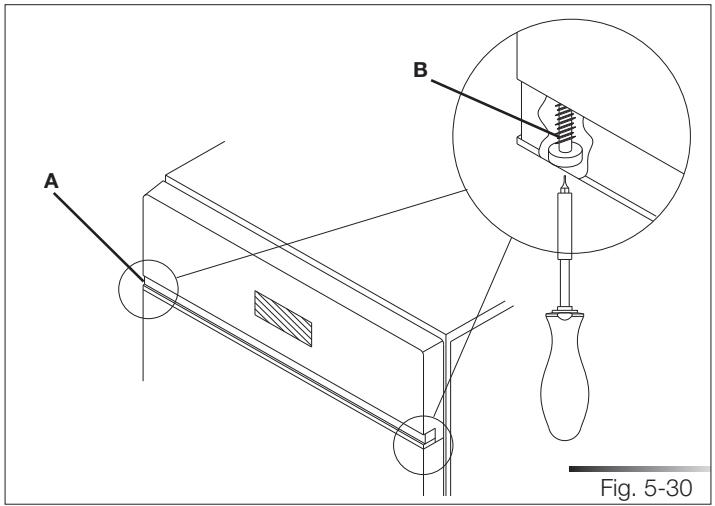
text_image
A B Fig. 5-30Attach the door panel: fit the hooks into their slots on the dishwasher and allow the panel to slide upwards and slip into place (see fig. 5-31).
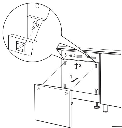
text_image
Technical diagram showing a device with labeled components and directional arrows, including a magnified inset of the component's view.Fig. 5-31
Secure the door to the panel with the supplied screws. The panel must have a minimum thickness of 20 mm (25/32") (see fig. 5-32).
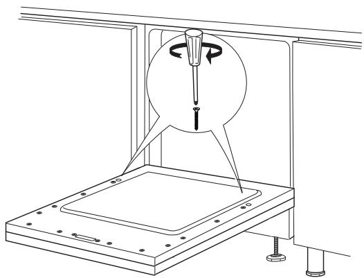
natural_image
Technical line drawing of a mechanical testing setup with a tool and base platform (no text or symbols)Fig. 5-32
Make sure the dishwasher door, complete with panel, opens comfortably and that the base plate (ref. A fig. 5-33) does not prevent it from opening fully. If the base plate prevents the door from opening, mark out the section to remove (see fig. 5-33), take out the base plate and cut it along the marking using a compass saw (see fig. 5-34).
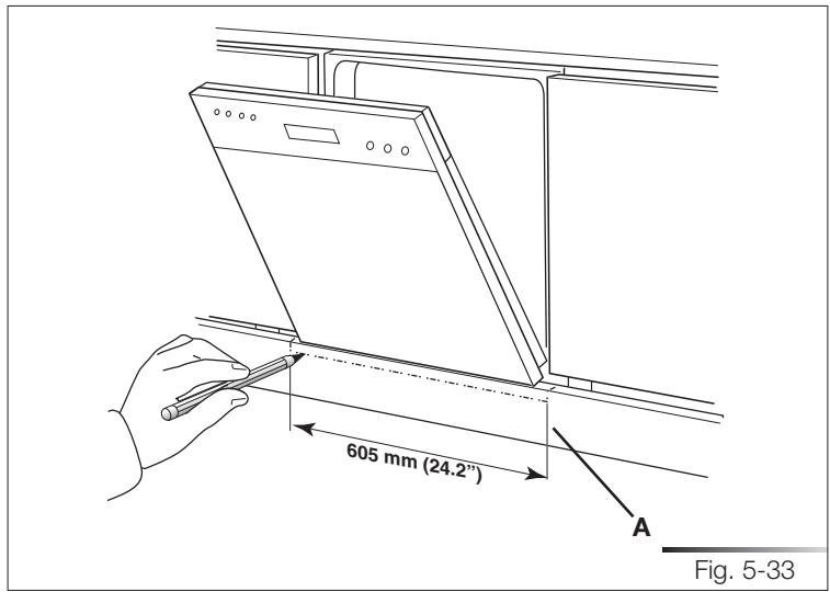
text_image
605 mm (24.2") A Fig. 5-33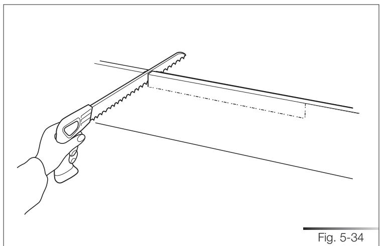
natural_image
Line drawing of a hand using a saw to cut a diagonal line, labeled as Fig. 5-34 (no text or symbols on the diagram itself)5.3.4 Completion of installation (all models)
Finish the cut with a file (see fig. 5-35) in order to remove any burrs and/or imperfections. Put back the base plate (see fig. 5-36) and try to open the dishwasher door fully; if the base plate still obstructs the door, repeat the above operations.
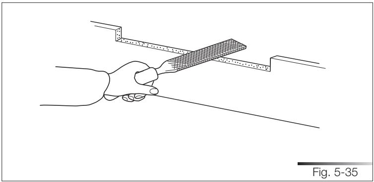
natural_image
Line drawing of a hand holding a ruler and a surface, with no text or symbols present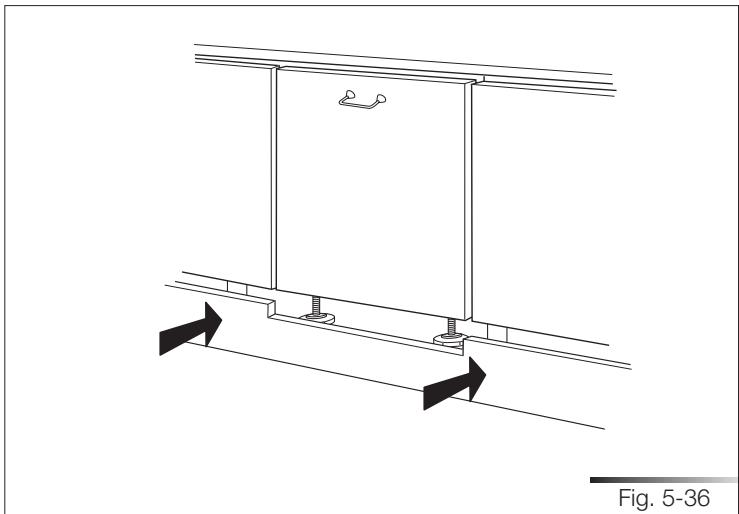
natural_image
Technical line drawing of a structural support frame with directional arrows indicating movement, labeled Fig. 5-36 (no text or symbols on the diagram itself)Before securing the dishwasher to the adjacent units, attach the gaskets to the sides.
Remove the adhesive band on the gasket (see fig. 5-37).
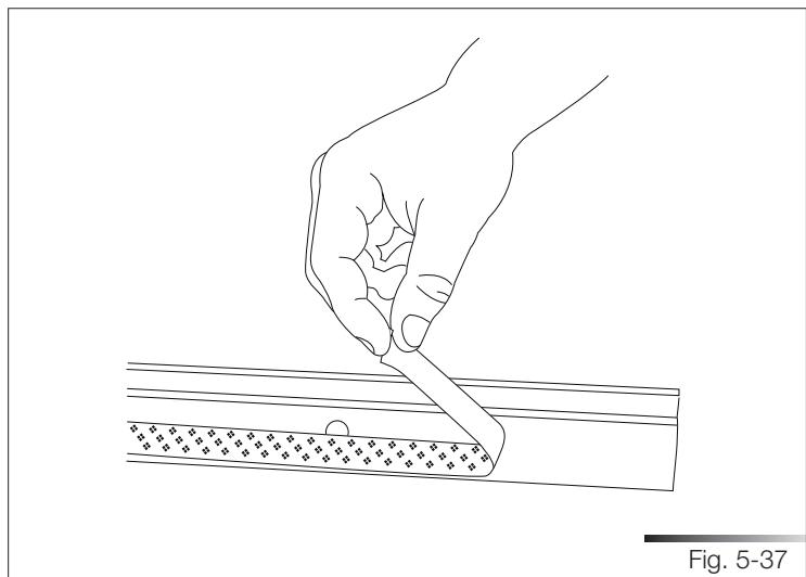
natural_image
Line drawing of a hand using a tool to cut or mark a rectangular object with grid patterns (no text or symbols)Fix the gasket to the dishwasher, inserting it in the seat on the sides towards the front (see fig. 5-38), and making sure that the long side of the gasket, the one with the hole for inserting the screw, is attached to the outside of the dishwasher; the hole in the long side must match the hole in the dishwasher (see ref. A fig. 5-39). Make sure the gasket adheres perfectly to the dishwasher.
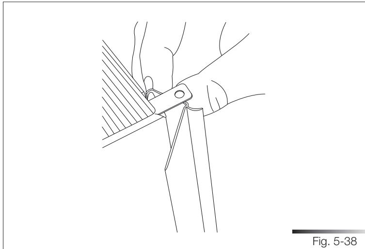
natural_image
Line drawing of hands using a tool to cut or spread materials, labeled as Fig. 5-38 (no text or symbols on the diagram itself)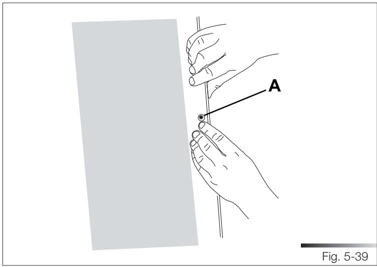
text_image
A Fig. 5-39Fig. 5-40 shows the state of the dishwasher after the above operations are performed.
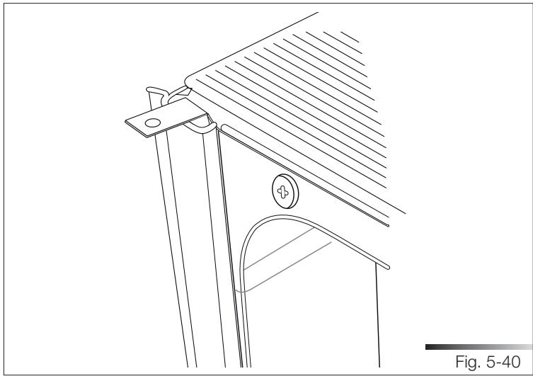
natural_image
Technical line drawing of a structural component with diagonal hatching and a circular feature, labeled as Fig. 5-40 (no text or symbols on the diagram itself)Tighten the supplied screws with a screwdriver; this operation definitively fixes the dishwasher to the adjacent units; cover the side holes using the supplied plugs (ref. A fig. 5-41).
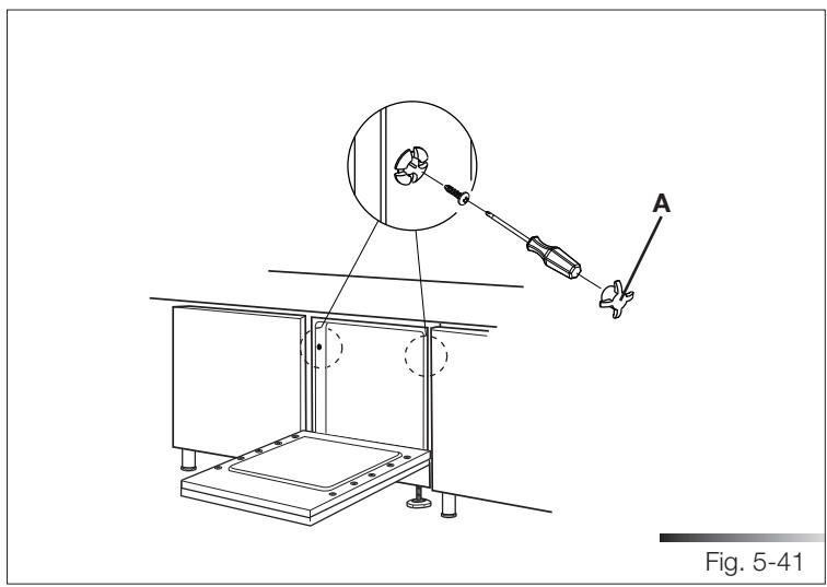
natural_image
Technical line drawing of a mechanical setup with a pulley system and labeled component A, no readable text or symbols present.5.4 Testing
After installation, test the dishwasher by starting a work cycle. Check for leaks and make sure the appliance does not malfunction.
598mm (23-35/64")
Align with the top edge of the door panel.
Align with the top edge of the door panel.