
H5X Element SST - Water dispenser Bunn - Free user manual and instructions
Find the device manual for free H5X Element SST Bunn in PDF.


| Type | Hot Water Dispenser |
| Brand | Bunn |
| Model | H5X Element SST |
| Category | Commercial Hot Water Dispenser |
| Power Supply | 100-120V AC or 200-240V AC, 2-wire + ground, single phase |
| Power Consumption | 4000W (at 240V) / 1800W (at 120V) |
| Tank Capacity | 5 gallons (approx.) |
| Temperature Control | Electronic, holds water at threshold of boiling; adjustable via programming on H5E models |
| Liquid Level Control | Automatic refill using probe and solenoid valve |
| Safety Overflow Switch | Yes, with float mechanism; interrupts power if overflow cup fills |
| Limit Thermostat | Yes, manual reset; prevents overheating |
| Steam Sensor (Thermistor) | Yes, on overflow tube; resistance 9KΩ at room temp to 2KΩ at 200°F |
| Dispense Valve | Solenoid-operated, behind control panel |
| Control Board | Electronic board with fault code indication via flashing power lamp |
| Fault Codes | Er1 (temp sensor short), Er2 (open), Er3 (refill fault), Er4 (heater fault), Er5 (boil thermistor short), Er6 (open) |
| Warranty | 2 years parts, 1 year labor; electronic boards 3 years |
| Maintenance | Regular deliming required; components accessible via rear panels |
| Water Pressure | Maximum 90 psi (620 kPa); recommended 50 psi (345 kPa) |
| Water Connection | Cold water line only |
| Service Access | Remove upper and lower rear panels; side panel on H10X |
Frequently Asked Questions - H5X Element SST Bunn
User questions about H5X Element SST Bunn
0 question about this device. Answer the ones you know or ask your own.
Ask a new question about this device
Download the instructions for your Water dispenser in PDF format for free! Find your manual H5X Element SST - Bunn and take your electronic device back in hand. On this page are published all the documents necessary for the use of your device. H5X Element SST by Bunn.
USER MANUAL H5X Element SST Bunn
natural_image
Illustration of various industrial appliances and devices, including fans, gauges, and oatmeal (no text or symbols visible)SERVICE MANUAL
BUNN-O-MATIC CORPORATION
To ensure you have the latest revision of the manual or to obtain the illustrated parts catalog, please visit the Bunn-O-Matic website, at www.bunn.com. This is absolutely FREE, and the quickest way to obtain the latest catalog and manual updates. Contact Bunn-O-Matic Corporation at 1-800-286-6070 to obtain a paper copy of the required Illustrated Parts Catalog mailed via U.S. Postal Service.

BUNN-O-MATIC COMMERCIAL PRODUCT WARRANTY
Bunn-O-Matic Corp. ("BUNN") warrants equipment manufactured by it as follows:
1) Airpots, thermal carafes, decanters, GPR servers, iced tea/coffee dispensers, MCR/MCP/MCA single cup brewers, thermal servers and ThermoFresh® servers (mechanical and digital) 1 year parts and 1 year labor.
2) All other equipment - 2 years parts and 1 year labor plus added warranties as specified below:
a) Electronic circuit and/or control boards - parts and labor for 3 years.
b) Compressors on refrigeration equipment - 5 years parts and 1 year labor.
c) Grinding burrs on coffee grinding equipment to grind coffee to meet original factory screen sieve analysis - parts and labor for 4 years or 40,000 pounds of coffee, whichever comes first.
These warranty periods run from the date of installation BUNN warrants that the equipment manufactured by it will be commercially free of defects in material and workmanship existing at the time of manufacture and appearing within the applicable warranty period. This warranty does not apply to any equipment, component or part that was not manufactured by BUNN or that, in BUNN's judgment, has been affected by misuse, neglect, alteration, improper installation or operation, improper maintenance or repair, non periodic cleaning and descaling, equipment failures related to poor water quality, damage or casualty. In addition, the warranty does not apply to replacement of items subject to normal use including but not limited to user replaceable parts such as seals and gaskets. This warranty is conditioned on the Buyer 1) giving BUNN prompt notice of any claim to be made under this warranty by telephone at (217) 529-6601 or by writing to Post Office Box 3227, Springfield, Illinois 62708-3227; 2) if requested by BUNN, shipping the defective equipment prepaid to an authorized BUNN service location; and 3) receiving prior authorization from BUNN that the defective equipment is under warranty.
THE FOREGOING WARRANTY IS EXCLUSIVE AND IS IN LIEU OF ANY OTHER WARRANTY, WRITTEN OR ORAL, EXPRESS OR IMPLIED, INCLUDING, BUT NOT LIMITED TO, ANY IMPLIED WARRANTY OF EITHER MERCHANTABILITY OR FITNESS FOR A PARTICULAR PURPOSE. The agents, dealers or employees of BUNN are not authorized to make modifications to this warranty or to make additional warranties that are binding on BUNN. Accordingly, statements by such individuals, whether oral or written, do not constitute warranties and should not be relied upon.
If BUNN determines in its sole discretion that the equipment does not conform to the warranty, BUNN, at its exclusive option while the equipment is under warranty, shall either 1) provide at no charge replacement parts and/or labor (during the applicable parts and labor warranty periods specified above) to repair the defective components, provided that this repair is done by a BUNN Authorized Service Representative; or 2) shall replace the equipment or refund the purchase price for the equipment.
THE BUYER'S REMEDY AGAINST BUNN FOR THE BREACH OF ANY OBLIGATION ARISING OUT OF THE SALE OF THIS EQUIPMENT, WHETHER DERIVED FROM WARRANTY OR OTHERWISE, SHALL BE LIMITED, AT BUNN'S SOLE OPTION AS SPECIFIED HEREIN, TO REPAIR, REPLACEMENT OR REFUND.
In no event shall BUNN be liable for any other damage or loss, including, but not limited to, lost profits, lost sales, loss of use of equipment, claims of Buyer's customers, cost of capital, cost of down time, cost of substitute equipment, facilities or services, or any other special, incidental or consequential damages.
392, A Partner You Can Count On, Air Infusion, AutoPOD, AXIOM, BrewLOGIC, BrewMETER, Brew Better Not Bitter, BrewWISE, BrewWIZARD, BUNN Espress, BUNN Family Gourmet, BUNN Gourmet, BUNN Pour-O-Matic, BUNN, BUNN with the stylized red line, BUNNlink, Bunn-OMatic, Bunn-O-Matic, BUNNserve, BUNNSERVE with the stylized wrench design, Cool Froth, DBC, Dr. Brew stylized Dr. design, Dual, Easy Pour, EasyClear, EasyGard, FlavorGard, Gourmet Ice, Gourmet Juice, High Intensity, iMIX, Infusion Series, Intellisteam, My Café, Phase Brew, PowerLogic, Quality Beverage Equipment Worldwide, Respect Earth, Respect Earth with the stylized leaf and coffee cherry design, Safety-Fresh, savemycoffee.com, Scale-Pro, Silver Series, Single, Smart Funnel, Smart Hopper, SmartWAVE, Soft Heat, SplashGard, The Mark of Quality in Beverage Equipment Worldwide, ThermoFresh, Titan, trifecta, TRIFECTA (sylized logo), Velocity Brew, Air Brew, Beverage Bar Creator, Beverage Profit Calculator, Brew better, not bitter., Build-A-Drink, BUNNSource, Coffee At Its Best, Cyclonic Heating System, Daypart, Digital Brewer Control, Element, Milk Texturing Fusion, Nothing Brews Like a BUNN, Picture Prompted Cleaning, Pouring Profits, Signature Series, Sure Tamp, Tea At Its Best, The Horizontal Red Line, Ultra are either trademarks or registered trademarks of Bunn-O-Matic Corporation. The commercial trifecta® brewer housing configuration is a trademark of Bunn-O-Matic Corporation.
WARNING - Inspection, testing, and repair of electrical equipment should be performed only by qualified service personnel. Disconnect the dispenser from the power source when servicing, except when electrical tests are required and the test procedure specifically states to connect the dispenser to the power source.
CONTENTS
TroubleShooting....4
Component Access 7
Electronic Controls....8-11
Limit Thermostat....12
Safety Overflow Switch 13
Solenoid Valve (Late Models)....14
Solenoid Valve (Early Models) 15
Tank Heater 16
Steam Sensor 17
Dispense Valve (H5-PC)....18
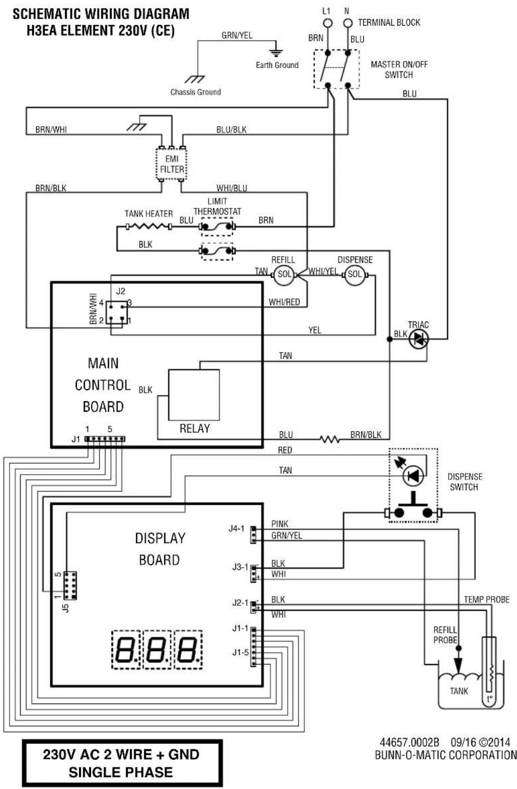
Dispense Valve (H3EA Element)....19
Dispense Switch (H3EA Element) 20
Mechanical Thermostat....21
Contactor 22
Liquid Level Board 23
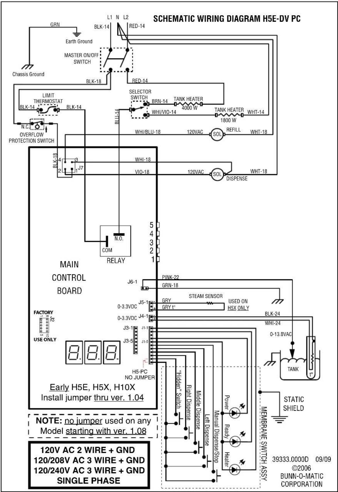
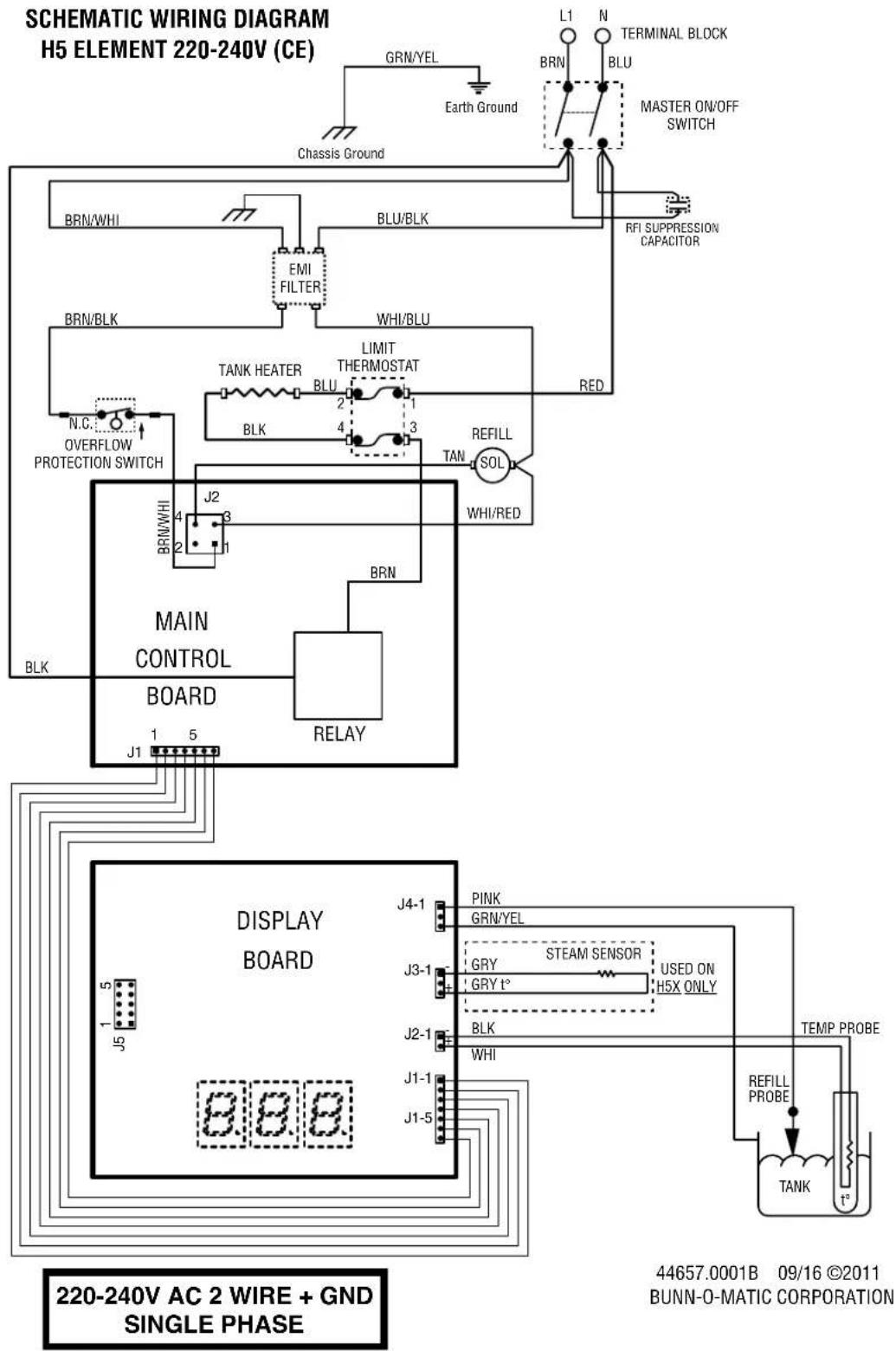
Schematic Wiring Diagrams....25
TROUBLESHOOTING
A troubleshooting guide is provided to suggest probable causes and remedies for the most likely problems encountered. If the problem remains after exhausting the troubleshooting steps, contact the Bunn-O-Matic Technical Service Department.
- Inspection, testing, and repair of electrical equipment should be performed only by qualified service personnel.
- All electronic components have 120 – 240 volt ac and low voltage dc potential on their terminals. Shorting of terminals or the application of external voltages may result in board failure.
- Intermittent operation of electronic circuit boards is unlikely. Board failure will normally be permanent. If an intermittent condition is encountered, the cause will likely be a switch contact or a loose connection at a terminal or crimp.
- Solenoid removal requires interrupting the water supply to the valve. Damage may result if solenoids are energized for more than ten minutes without a supply of water.
- The use of two wrenches is recommended whenever plumbing fittings are tightened or loosened. This will help to avoid twists and kinks in the tubing.
- Make certain that all plumbing connections are sealed and electrical connections tight and isolated.
- This dispenser is heated at all times. Keep away from combustibles.
WARNING
• Exercise extreme caution when servicing electrical equipment.
- Disconnect dispenser from the power source when servicing, except when electrical tests are specified.
- Follow recommended service procedures
- Replace all protective shields or safety notices
When a fault occurs (failure to the unit) the POWER lamp will flash to identify the problem (early models)
FAULT CODES
| Flashes | Description of Failure | ||
| Er1 | Temperature Sensor (short) | 1 | Temperature Sensor (short) |
| Er2 | Temperature Sensor (open) | 2 | Temperature Sensor (open) |
| Er3 | Refill Fault (continuous refill for 15 minutes) | 3 | Refill Fault (continuous refill for 15 minutes) |
| Er4 | Heater Fault (heater relay on for 120 minutes) | 4 | Heater Fault (heater relay on for 120 minutes) |
| Er5 | Boil Thermistor (short) H5X/H10X only) | 5 | Boil Thermistor (short) H5X/H10X only |
| Er6 | Boil Thermistor (open) H5X/H10X only) | 6 | Boil Thermistor (open) H5X/H10X only |
Problem
Equipment will not operate.
Probable Cause
- No power or incorrect voltage
Remedy
(A) Check the terminal block for the correct voltage. It should be:
a.) 100 to 120 volts ac across the black and white terminals for 100 to 120 volt models or,
b.) 200 to 240 volts ac across the red and black terminals for 200 to 240 volt models or,
c.) 230 volts ac across the red and black terminals for 230 volt models.
(B) Check circuit breakers or fuses.
42311 071310
TROUBLESHOOTING (cont.)
Problem Probable Cause Remedy
| Equipment will not operate (cont.) | 2. Safety overflow switch | Refer to Service – safety overflow switch for testing procedures. |
| Automatic refill will not operate after drawing hot water. | 1. No water | Check plumbing and shut-off valves. |
| 2. Water strainer/flow control | (A) Direction of flow arrow must be pointing towards dispenser. | |
| (B) Remove the strainer/flow control and check for obstructions. Clear or replace. | ||
| 3. Liquid level system | Refer to Service – electronic controls for testing procedures. | |
| 4. Solenoid valve | Refer to Service – solenoid valve for testing procedures. | |
| Water flows into the tank continuously (Dispenser disconnected from power source). | 1. Solenoid valve | Refer to Service – solenoid valve for testing procedures. |
| Water flows into the tank continuously (Dispenser connected to power source). | 1. Liquid level system | Refer to Service – electronic controls for testing procedures. |
| Water is cold. | 1. Safety overflow switch | Refer to Service – safety overflow switch for testing procedures. |
| 2. Limit thermostat | Refer to Service – limit thermostat for testing procedures. |
CAUTION – Do not eliminate or bypass limit thermostat. Use only B.O.M. replacement part #23717.0003.
- Tank heater Refer to Service – tank heater for testing procedures.
- Temperature control Refer to Service – electronic controls for testing procedures.
TROUBLESHOOTING (cont.)
Problem Probable Cause Remedy
| Water boils continuously. | 1. Temperature control | Refer to Service – electronic controls for testing procedures. |
| 2. Lime build-up | Inspect the tank assembly for excess lime deposits. Delime as required. |
CAUTION – Tanks and tank components should be delimed regularly depending on local water conditions. Excessive mineral build-up on stainless steel surfaces can initiate corrosive reactions resulting in serious leaks.
| Dispenser is making unusual noises. | 1. Plumbing lines | Plumbing lines should not be resting on the counter top. |
| 3. Water supply | (A) The dispenser must be connected to a cold water line. | |
| (B) Water pressure to the dispenser must not be higher than 90 psi (620 kPa). Install a regulator if necessary to lower the working pressure to approximately 50 psi (345 kPa). | ||
| Ready indicator will not light. | 1. Temperature control | Refer to Service – electronic controls for testing procedures. |
| 2. Ready Indicator LED | Replace the indicator LED. |
SERVICE
WARNING – Disconnect the dispenser from the power source before the removal of any panel or the replacement of any component. WARNING - Inspection, testing, and repair of electrical equipment should be performed only by qualified service personnel. Disconnect the dispenser from the power source when servicing, except when electrical tests are required and the test procedure specifically states to connect the dispenser to the power source.
Component Access - H3/H5E/DV-PC/X Component Access - H10X
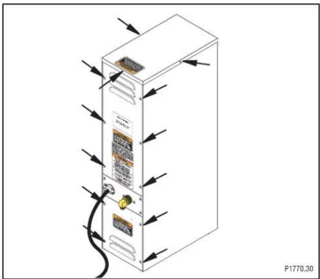
The check valve, electronic control assembly, safety overflow switch, solenoid valve, overflow tube temperature sensor and terminal block are located at the rear of the dispenser. Access is gained by removing the upper and lower rear panels. The upper is attached with six 8-32 slotted-head screws. The lower is attached with four 8-32 slotted-head screws. The middle panel must not be removed from the dispenser.
natural_image
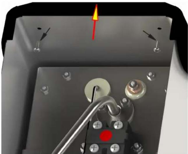
Close-up of a mechanical or electrical component with a red arrow indicating direction, no visible text or symbolsFaceplate Removal - H3/5 ELEMENT: After removing top cover, remove the two upper screws securing the faceplate. Carefully lift faceplate straight up until the lower screws clear the key holes.
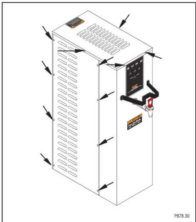
The check valve, electronic control assembly, overflow protection switch, solenoid valve, overflow tube temperature sensor, triac assembly (EARLY MODELS ONLY) and terminal block are located on the side of the dispenser. Access is gained by removing the side panel. The panel is attached with eight 8-32 slotted-head screws.
SERVICE
Electronic Controls
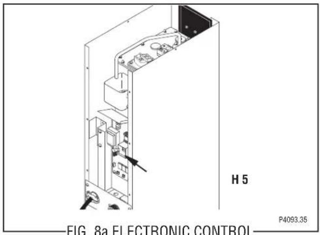
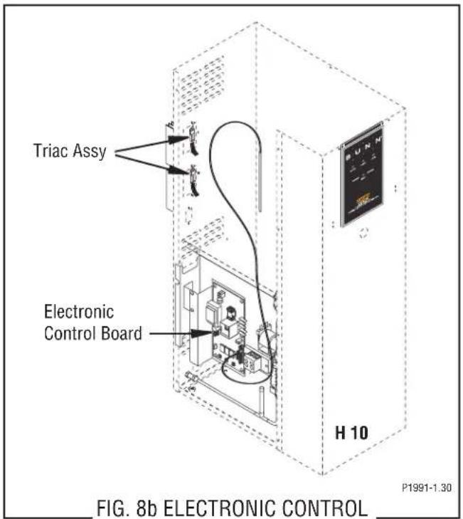
BOARD AND TRIAC
Location:
The electronic control board is located inside the rear of the dispenser (digital 5 gallon models). 3 & 5 gallon Elements control boards are located in the front shroud. Access will also be needed to the temperature sensor, overflow tube temperature sensor, and liquid level probe located on the tank lid.
General:
This system controls the liquid level and water temperature of the dispenser. These two functions act independently of each other and should be tested separately.
Liquid Level Control Flow Charts
H3/5/10 LIQUID LEVEL CONTROL
PROBLEM: Does Not Refill
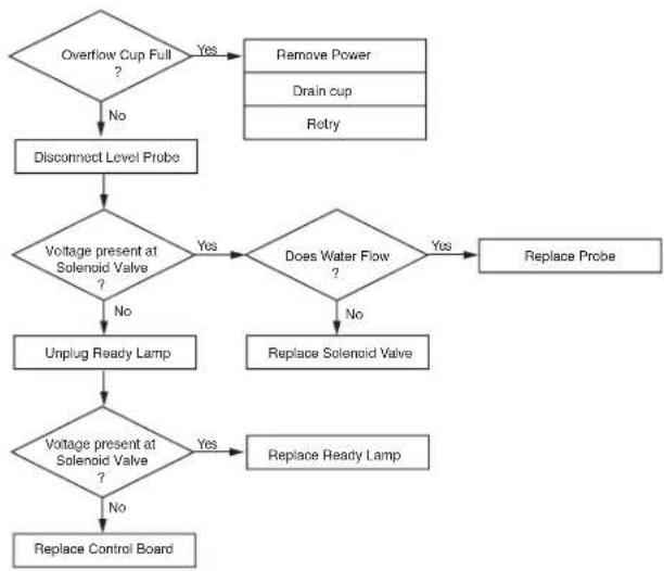
flowchart
graph TD
    A{Overflow Cup Full ?} -->|Yes| B["Remove Power"]
    A -->|No| C["Disconnect Level Probe"]
    C --> D{Voltage present at Solenoid Valve ?}
    D -->|Yes| E{Does Water Flow ?}
    D -->|No| F["Unplug Ready Lamp"]
    E -->|Yes| G["Replace Probe"]
    E -->|No| H["Replace Solenoid Valve"]
    F --> I{Voltage present at Solenoid Valve ?}
    I -->|Yes| J["Replace Ready Lamp"]
    I -->|No| K["Replace Control Board"]
H3/5/10 LIQUID LEVEL CONTROL
PROBLEM: Overflows
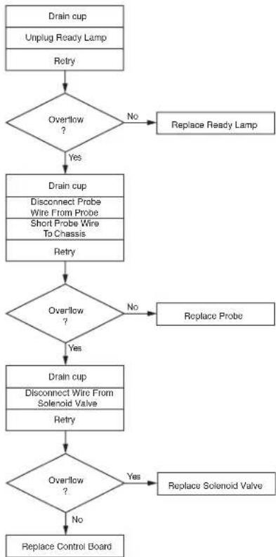
flowchart
graph TD
    A["Drain cup\nUnplug Ready Lamp\nRetry"] --> B{Overflow?}
    B -->|No| C["Replace Ready Lamp"]
    B -->|Yes| D["Drain cup\nDisconnect Probe\nWire From Probe\nShort Probe Wire\nTo Chassis\nRetry"]
    D --> E{Overflow?}
    E -->|No| F["Replace Probe"]
    E -->|Yes| G["Drain cup\nDisconnect Wire From\nSolenoid Valve\nRetry"]
    G --> H{Overflow?}
    H -->|Yes| I["Replace Solenoid Valve"]
    H -->|No| J["Replace Control Board"]
SERVICE (cont.)
Electronic Controls (cont.)
Liquid Level Control Test Procedure
- Disconnect the dispenser from the power source.
- Check the voltage across terminals 3 & 4 of the electronic control board with a voltmeter. Connect the dispenser to the power source. The indication must be:
a.) 100 to 120 volts ac for 100 to 120 volt models or
b.) 200 to 240 volts ac for 200 to 240 volt models or
c.) 230 volts ac for 230 volt models.
-
Disconnect the dispenser from the power source. If voltage was present as described, proceed to #4. If voltage was not present as described, refer to the Wiring Diagrams and check the dispenser wiring harness.
-
Remove the pink wire from terminal 5 of the electronic control assembly.
- Check the voltage across terminals 1 & 4 of the electronic control board with a voltmeter. Connect the dispenser to the power source. The indication must be:
a.) 100 to 120 volts ac for 100 to 120 volt models or
b.) 200 to 240 volts ac for 200 to 240 volt models or
c.) 230 volts ac for 230 volt models after a delay of approximately 5 seconds.
- Disconnect the dispenser from the power source.
If voltage was present as described, the liquid level control of the system is operating properly, proceed to #7. If voltage was not present as described, replace the electronic control board and the temperature sensor in the tank lid.
Temperature Control Flow Charts
H5/10X THERMOSTAT H3/5E THERMOSTAT
PROBLEM: Water Not Hot Enough
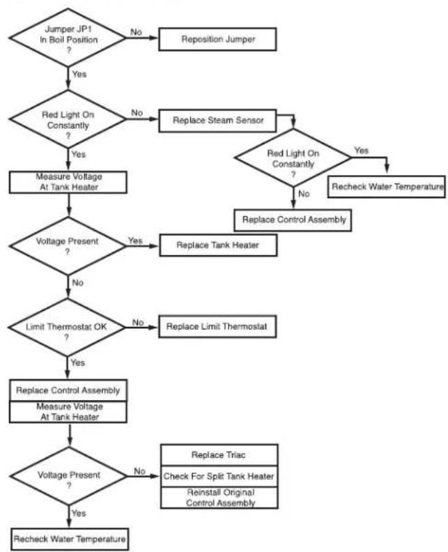
flowchart
graph TD
    A["Jumper JP1 In Boil Position ?"] -->|Yes| B{Red Light On Constantly ?}
    B -->|No| C["Replace Steam Sensor"]
    B -->|Yes| D["Measure Voltage At Tank Heater"]
    C --> D
    D --> E{Voltage Present ?}
    E -->|Yes| F["Replace Control Assembly"]
    E -->|No| G{Limit Thermostat OK ?}
    G -->|No| H["Replace Limit Thermostat"]
    G -->|Yes| I["Replace Control Assembly\nMeasure Voltage At Tank Heater"]
    I --> J{Voltage Present ?}
    J -->|No| K["Replace Triac\nCheck For Split Tank Heater\nReinstall Original Control Assembly"]
    J -->|Yes| L["Recheck Water Temperature"]
    C --> M{Red Light On Constantly ?}
    M -->|No| N["Replace Control Assembly"]
    M -->|Yes| O["Recheck Water Temperature"]
SERVICE (cont.)
PROBLEM: Water Not Hot Enough
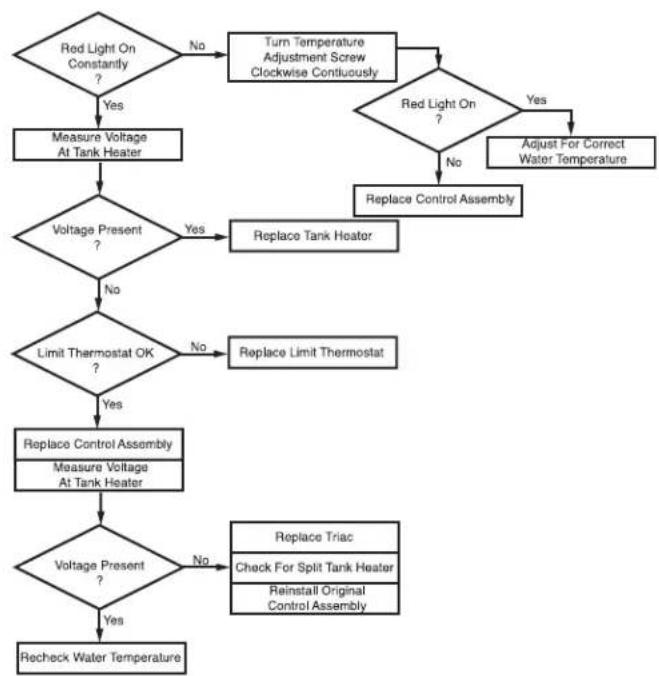
flowchart
graph TD
    A{Red Light On Constantly ?} -->|Yes| B["Measure Voltage At Tank Heater"]
    A -->|No| C["Turn Temperature Adjustment Screw Clockwise Continuously"]
    C --> D{Red Light On ?}
    D -->|Yes| E["Adjust For Correct Water Temperature"]
    D -->|No| F["Replace Control Assembly"]
    B --> G{Voltage Present ?}
    G -->|Yes| H["Replace Tank Heater"]
    G -->|No| I{Limit Thermostat OK ?}
    I -->|Yes| J["Replace Control Assembly"]
    I -->|No| K["Replace Limit Thermostat"]
    J --> L["Measure Voltage At Tank Heater"]
    L --> M{Voltage Present ?}
    M -->|Yes| N["Recheck Water Temperature"]
    M -->|No| O["Replace Triac"]
    O --> P["Check For Split Tank Heater"]
    O --> Q["Reinstall Original Control Assembly"]
Electronic Controls (cont.)
- Reconnect the pink wire to terminal 5 of the electronic control assembly.
- Loosen the compression fitting, remove the probe from the tank lid, and inspect it for mineral deposits. Replace it if necessary. Keep the exposed ends of the probe away from any metal surface of the dispenser.
- Check the voltage across terminals 1 & 4 of the electronic control assembly with a voltmeter. Connect the dispenser to the power source. The indication must be:
a.) 100 to 120 volts ac for 100 to 120 volt models or
b.) 200 to 240 volts ac for 200 to 240 volt models or
c.) 230 volts ac for 230 volt models after a delay of approximately 5 seconds.
- Touch the screw head end of the probe to the dispenser housing. The indication must be 0.
- Move the probe away from the dispenser housing. The indication must again be:
a.) 100 to 120 volts ac for 100 to 120 volt models or
b.) 200 to 240 volts ac for 200 to 240 volt models or
c.) 230 volts ac for 230 volt models after a delay of approximately 5 seconds.
- Disconnect the dispenser from the power source.
Temperature Control Flow Charts (cont.)
If voltage was present as described, reinstall the probe, the sensing function of the system is operating properly. H5/10X THERMOSTAT H3/5E THERMOSTAT
PROBLEM: Boils Excessively - Fills Cup
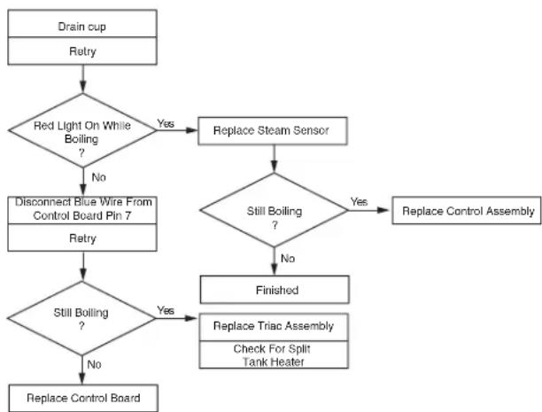
flowchart
graph TD
    A["Drain cup\nRetry"] --> B{Red Light On While Boiling?}
    B -->|Yes| C["Replace Steam Sensor"]
    B -->|No| D["Disconnect Blue Wire From Control Board Pin 7\nRetry"]
    D --> E{Still Boiling?}
    E -->|Yes| F["Replace Triac Assembly\nCheck For Split Tank Heater"]
    E -->|No| G["Replace Control Board"]
    C --> H{Still Boiling?}
    H -->|Yes| F
    H -->|No| I["Finished"]
    F --> J["Replace Control Assembly"]
If voltage was not present as described, check the pink probe wire and the green ground wire for continuity and/or replace the probe.
Temperature Control Test Procedure
- Disconnect the dispenser from the power source.
- Check the voltage across terminals 3 & 4 of the electronic control circuit board with a voltmeter. Connect the dispenser to the power source. The indication must be:
a.) 100 to 120 volts ac for 100 to 120 volt models or
b.) 200 to 240 volts ac for 200 to 240 volt models or
c.) 230 volts ac for 230 volt models.
-
Disconnect the dispenser from the power source.
-
Check the voltage across the tank heater terminals with a voltmeter. Connect the dispenser to the power source. The indication must be:
a.) 100 to 120 volts ac for 100 to 120 volt models or
b.) 200 to 240 volts ac for 200 to 240 volt models or
c.) 230 volts ac for 230 volt models.
- Disconnect the dispenser from the power source.
H5E THERMOSTAT
PROBLEM: Boils
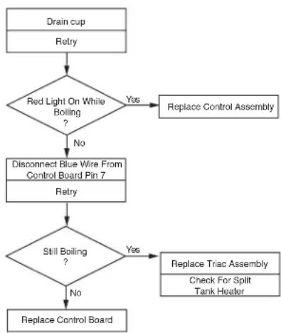
flowchart
graph TD
    A["Drain cup\nRetry"] --> B{Red Light On While Boiling?}
    B -->|Yes| C["Replace Control Assembly"]
    B -->|No| D["Disconnect Blue Wire From Control Board Pin 7\nRetry"]
    D --> E{Still Boiling?}
    E -->|Yes| F["Replace Triac Assembly\nCheck For Split Tank Heater"]
    E -->|No| G["Replace Control Board"]
SERVICE (cont.)
Electronic Controls (cont.)
If voltage was present as described, the temperature control of the system is operating properly.
If voltage was not present as described, contact Bunn-O-Matic to order an electronic control board and temperature sensor for evaluation and proceed to #9.
- Replace the electronic control board.
- Check the voltage across the tank heater terminals with a voltmeter. Connect the dispenser to the power source. The indication must be:
a.) 100 to 120 volts ac for 100 to 120 volt models or
b.) 200 to 240 volts ac for 200 to 240 volt models or
c.) 230 volts ac for 230 volt models
- Disconnect the dispenser from the power source.
If voltage was present as described, the temperature control of the system is operating properly. Return the new electronic control board or temperature sensor to Bunn-O-Matic for credit.
Electronic Controls Removal and Replacement
- Remove all wires from the electronic control board terminals.
- Remove the six 6-32 screws holding the electronic control board to the component bracket.
- Disconnect the temperature sensor, overflow tube temperature sensor, and indicator wires from the electronic control board.
- Attach the temperature sensor, overflow tube temperature sensor, and indicator wires to the electronic control assembly.
- Fasten the new electronic control board to its bracket.
- Refer to Fig 2 when reconnecting the wires.
- Review the initial set-up procedures on page 6.
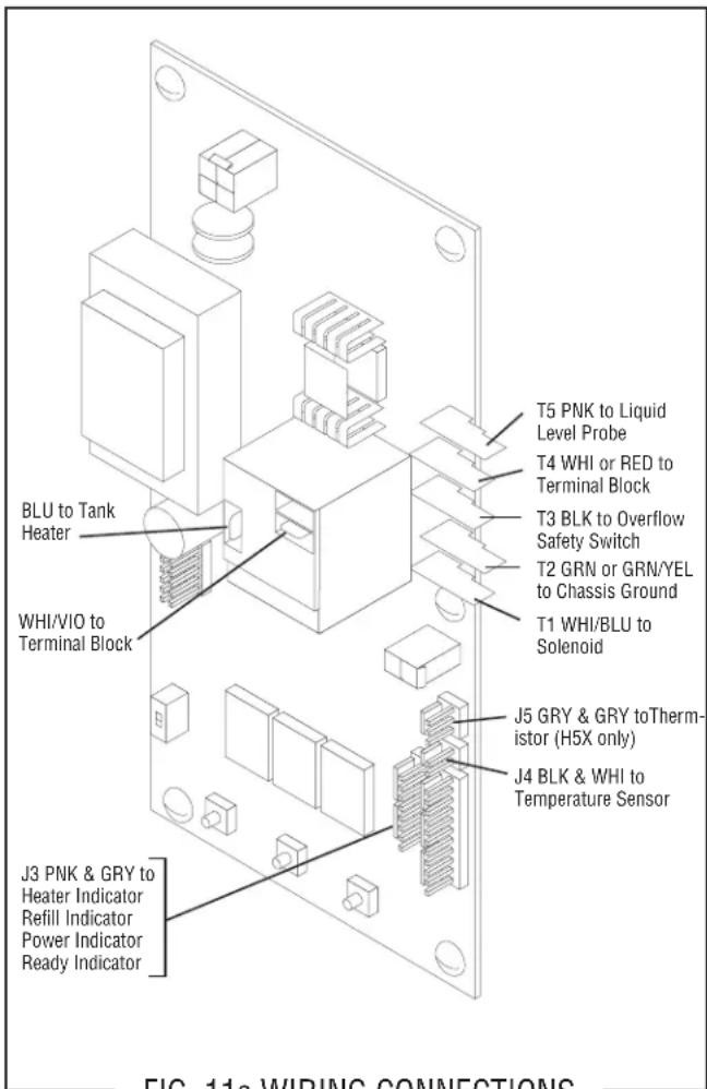
FIG. 11a WIRING CONNECTIONS
Adjustments
The H5X/H10X dispensers hold the water temperature at the threshold of boiling. It is not adjustable by the user.
The H5E dispenser is factory calibrated for the temperature specified on the data plate. If adjustment is required, use the following procedure:
- Fill the dispenser according to the steps in the Initial Set-up.
- Take the temperature of the stream of water immediately below the faucet as it flows from the dispenser with an accurate thermometer. Do not take the temperature of water collected in a container.
- If any adjustment is required, refer to LEVEL 1 PROGRAMMING in the Operating Manual.
SERVICE (cont.)
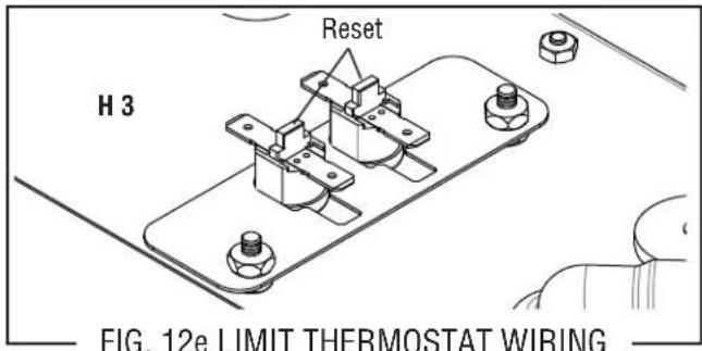
Limit Thermostat
Location:
The limit thermostat is located on the tank lid. To test the limit thermostat, access will also be needed to the terminal block located at the rear of the dispenser.
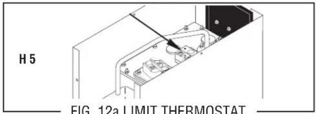
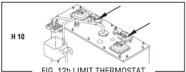
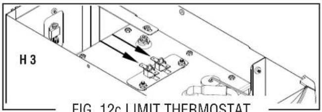
Test Procedure:
- Disconnect the dispenser from the power source.
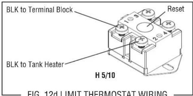
- There are two black wires on the limit thermostat terminals. One comes from the terminal block. The other goes directly to the tank heater terminal. Remove the black wire at the limit thermostat coming from the terminal block.
- Check the voltage across the black wire removed from the limit thermostat and the white wire or red wire of the terminal block with a voltmeter. Connect the dispenser to the power source. The indication must be:
a.) 100 to 120 volts ac for 100 to 120 volt models or
b.) 200 to 240 volts ac for 200 to 240 volt models or
c.) 230 volts ac for 230 volt models.
- Disconnect the dispenser from the power source.
If voltage was present as described, reconnect the black wire and proceed to #5.
If voltage was not present as described, refer to the Wiring Diagrams and check the dispenser wiring harness.
- Check for continuity across the terminals of the limit thermostat.
If continuity is not present as described, the circuit is broken. Press the reset button of the limit thermostat and recheck for continuity.
If continuity is not present as described, replace the limit thermostat.
Removal and Replacement:
- Remove both wires from the limit thermostat terminals.
- Remove the two #10-32 nuts attaching the limit thermostat to the top of the tank.
- Install the new limit thermostat and secure into place with two #10-32 nuts.
- Refer to schematic wiring diagrams when reconnecting the wires.
SERVICE (cont.)
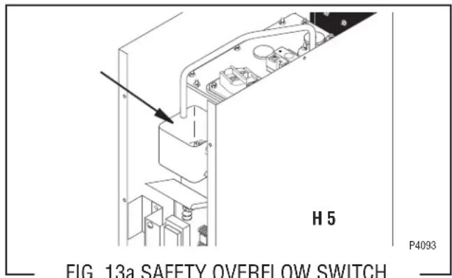
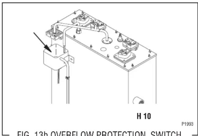
Safety Overflow Switch
Location:
The safety overflow switch is located inside the rear of the dispenser inside the copper overflow cup.
For testing or removal of the safety overflow switch, access may also be needed by removing the two screws attaching the electronic control assembly to its mounting bracket.
Test Procedure:
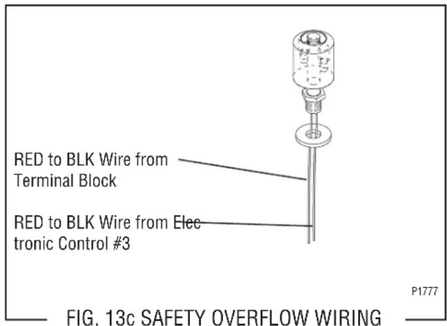
- Once voltage is verified at the power source, check for continuity across the safety overflow switch red wires only until the plastic float is raised and check that continuity returns when the plastic float is again lowered.
If continuity is present as described, reconnect each of the red wires to the black wires, the safety overflow switch is operating properly.
If continuity is not present as described, replace the safety overflow switch.
Removal and Replacement:
- Disconnect the black wires from the safety overflow switch.
- Remove the nut beneath the copper overflow cup.
- Remove the entire switch assembly from the cup.
- Place the new switch assembly into the cup, wires first. Make sure that a gasket is in place around the threaded switch stem.
NOTE - The magnets must be at the top of the float and there must be NO stainless steel washers installed for the safety overflow switch to operate properly.
- Install the nut beneath the copper overflow cup. Be sure not to overtighten.
- Reconnect the wires, FIG. 6.
SERVICE (cont.)
Solenoid Valve (Late Models)
Location:
The solenoid valve is located inside the rear of the dispenser on the right side near the bottom.
To test the solenoid valve, access will also be needed to the electronic control board.
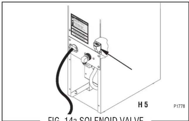
FIG. 14a SOLENOID VALVE
Test Procedure:
- Disconnect the dispenser from the power source and turn-off the water supply to the dispenser.
- Remove the pink wire from terminal 5 of the electronic control board.
-
Check the voltage across the solenoid valve coil terminals with a voltmeter. Connect the dispenser to the power source. The indication must be:
a.) 100 to 120 volts ac for 100 to 120 volt models or
b.) 200 to 240 volts ac for 200 to 240 volt models or
c.) 230 volts ac for 230 volt models after a delay of approximately 5 seconds. -
Disconnect the dispenser from the power source.
If voltage was present as described, proceed to #5. If voltage was not present as described, refer to the Wiring Diagrams and check the dispenser wiring harness.
- Remove both wires from the solenoid valve coil terminals.
- Check for continuity across the solenoid valve coil terminals.
If continuity is present as described, reconnect the wires and proceed to #7.
If continuity is not present as described, replace the solenoid valve coil.
- Check the solenoid valve for coil action. Connect the dispenser to the power source. Listen carefully in the vicinity of the solenoid valve for a "clicking"
sound after approximately 5 seconds, as the coil magnet attracts the plunger.
- Disconnect the dispenser from the power source.
- Reconnect the pink wire to terminal 5 of the electronic control board.
If the sound was heard as described and water will not pass through the solenoid valve, there may be a blockage in the water line before or after the solenoid valve or the solenoid valve may require inspection for wear and removal of waterborne particles.
If the sound was not heard as described, replace the solenoid valve.
Removal and Replacement:
- Remove all wires from the solenoid valve coil.
- Turn-off the water supply to the dispenser.
- Disconnect the water line from the solenoid valve.
- Remove the two 8-32 slotted-head screws holding the solenoid valve and mounting bracket to the back panel.
- Lift-out the solenoid valve.
- Securely install the new solenoid valve to the back panel.
- Securely fasten the water line to the solenoid valve.
- Reconnect the wires, FIG. 8.
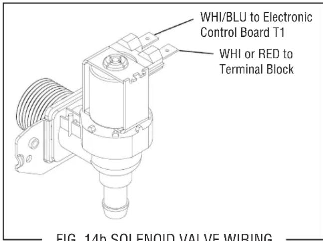
FIG. 14b SOLENOID VALVE WIRING
SERVICE (cont.)
Solenoid Valve (Early Models)
Location:
The solenoid valve is located behind the large access panel on the left side of the dispenser.
To test the solenoid valve, access will also be needed to the electronic control board.
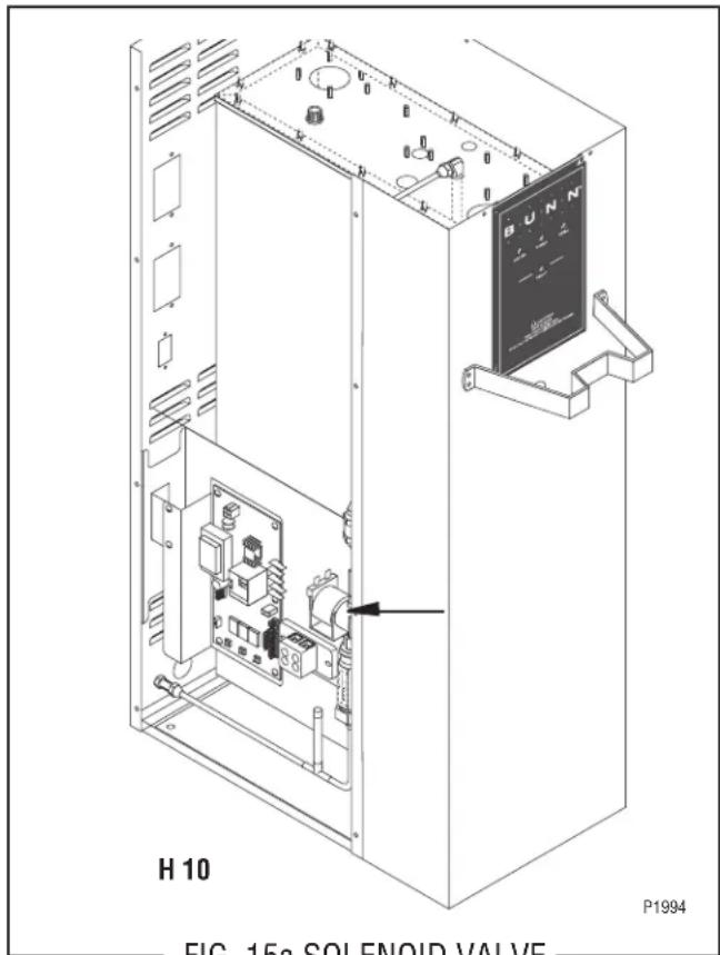
FIG. 15a SOLENOID VALVE
Test Procedure:
- Disconnect the dispenser from the power source and turn off the water supply to the dispenser.
- Remove the pink wire from terminal 5 of the electronic control board.
- Check the voltage across the solenoid valve coil terminals with a voltmeter. Connect the dispenser to the power source. The indication must be 200 to 240 volts ac for 200 to 240 volt models after a delay of approximately 5 seconds.
- Disconnect the dispenser from the power source.
If voltage was present as described, proceed to #5. If voltage was not present as described, refer to the Wiring Diagrams and check the dispenser wiring harness.
- Remove both wires from the solenoid valve coil terminals.
- Check for continuity across the solenoid valve coil terminals.
If continuity is present as described, reconnect the wires and proceed to #7.
If continuity is not present as described, replace the solenoid valve coil.
- Check the solenoid valve for coil action. Connect the dispenser to the power source. Listen carefully in the vicinity of the solenoid valve for a "clicking" sound after approximately 5 seconds, as the coil magnet attracts the plunger.
- Disconnect the dispenser from the power source.
- Reconnect the pink wire to terminal 5 of the electronic control board.
If the sound was heard as described and water will not pass through the solenoid valve, there may be a blockage in the water line before or after the solenoid valve or the solenoid valve may require inspection for wear and removal of waterborne particles.
If the sound was not heard as described, replace the solenoid valve.
Removal and Replacement:
- Remove all wires from the solenoid valve coil.
- Turn off the water supply to the dispenser.
- Disconnect the water lines to and from the solenoid valve.
- Remove the two 8-32 slotted-head screws holding the solenoid valve and mounting bracket to the component bracket.
- Lift out the solenoid valve.
- Remove the two 10-32 slotted-head screws holding the solenoid valve to its mounting bracket.
- Securely install the new solenoid valve to its mounting bracket. The direction of flow arrow must be pointing towards the tank lid.
- Attach the solenoid valve and mounting bracket to the component bracket.
- Securely fasten the water lines to and from the solenoid valve.
- Reconnect the wires, FIG. 8.
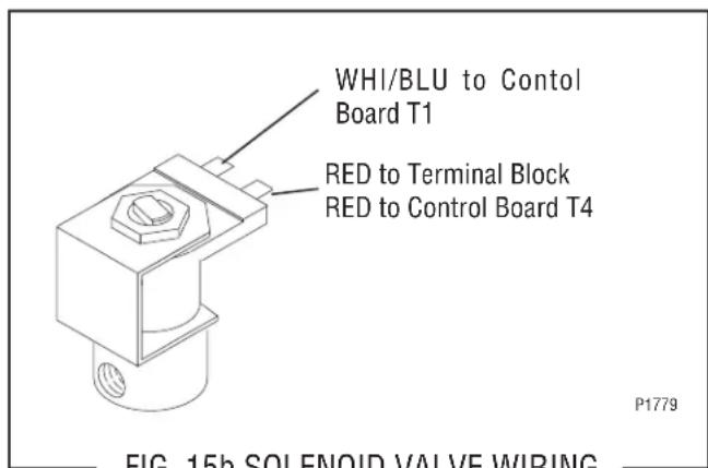
FIG. 15b SOLENOID VALVE WIRING
SERVICE (cont.)
Tank Heater
Location:
The tank heater is located in the tank lid.
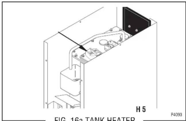
FIG. 16a TANK HEATER
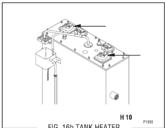
FIG. 16b TANK HEATER
Test Procedure:
- Disconnect the dispenser from the power source.
- Check the voltage across the terminals of the tank heater with a voltmeter. Connect the dispenser to the power source. The indication must be:
a.) 100 to 120 volts ac for 100 to 120 volt models or
b.) 200 to 240 volts ac for 200 to 240 volt models or
c.) 230 volts ac for 230 volt models.
- Disconnect the dispenser from the power source.
If voltage is present as described, proceed to #4.
If voltage is not present as described, replace the tank heater.
- Remove the tank heater from the tank lid and inspect it for cracks in the sheath.
If the sheath shows no sign of damage, proceed to #5. If the sheath is damaged, replace the tank heater. - Check for continuity across the tank heater terminals.
If continuity is present as described, reinstall the tank heater. The tank heater is operating properly.
If continuity is not present as described, replace the tank heater.
Removal and Replacement:
- Remove the wires to the tank heater.
- Remove the 8-32 nuts from the tank heater flange.
- Remove the tank heater.
- Inspect the tank heater gasket and replace if necessary.
- Securely install the new tank heater. Be certain of a watertight seal.
- Refer to schematic wiring diagrams when reconnecting the wires.
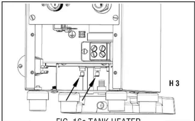
FIG. 16c TANK HEATER
| HEATER | COLD RESISTANCE | |||
| 1800W-120V | 7.44 | - 8.67 | Ω | Ω |
| 4000W-240V | 13.43 | - 15.51 | Ω | Ω |
| 4000W-208V | 10.09 | - 11.99 | Ω | Ω |
| 6000W-240V | 8.85 | - 10.23 | Ω | Ω |
| 6000W-208V | 6.67 | - 7.70 | Ω | Ω |
| 3000W-240V | 17.90 | - 20.90 | Ω | Ω |
| 1680W-120V | 7.90 | - 9.20 | Ω | Ω |
| TERMINAL TO SHEATH - INFINITE (OPEN) | ||||
SERVICE (cont.)
Steam Sensor (Thermistor)
Location:
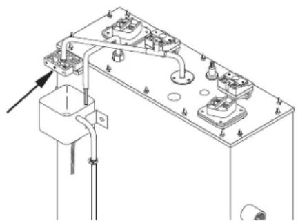
The thermistor is located on the end of the overflow tube above the overflow cup.
To test the thermistor, access will also be needed to the electronic control board.
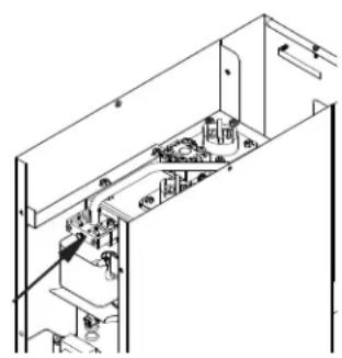
natural_image
Isometric line drawing of a room interior with furniture and fixtures (no text or symbols)H 5X
P1993
FIG. 17a LOCATION
natural_image
Technical line drawing of a mechanical assembly with mounting brackets and piping (no text or symbols)H 10X
P1993
FIG. 17b LOCATION
Test Procedure:
- Disconnect the dispenser from the power source.
- Disconnect the thermistor from J5 on control board.
- Check the resistance across thermistor with a ohmmeter. The resistance range is approximately 9KΩ@ room temperature to approximately 2K @ 200°F.
- Disconnect the dispenser from the power source.
If resistance was present as described, the thermistor is working.
If resistance was not present as described, replace the control board.
Removal and Replacement:
- Disconnect the dispenser from the power source.
- Disconnect the thermistor from J5 on control board.
- Loosen the set screw and the two screws securing the two half blocks together. Remove thermistor assembly from overflow tube.
- Install new thermistor on tube and slide down until it contacts the flared end. NOTE: It's critical that the thermistor be centered directly under the tube opening.
- Snug the set screw so the block assembly does not move around easily.
- Connect the thermistor to J5 on control board.
NOTE: DO NOT TEST OPERATION WITH PANELS REMOVED, AS AIR MOVEMENT CAN HINDER PROPER READINGS ON THERMISTOR.
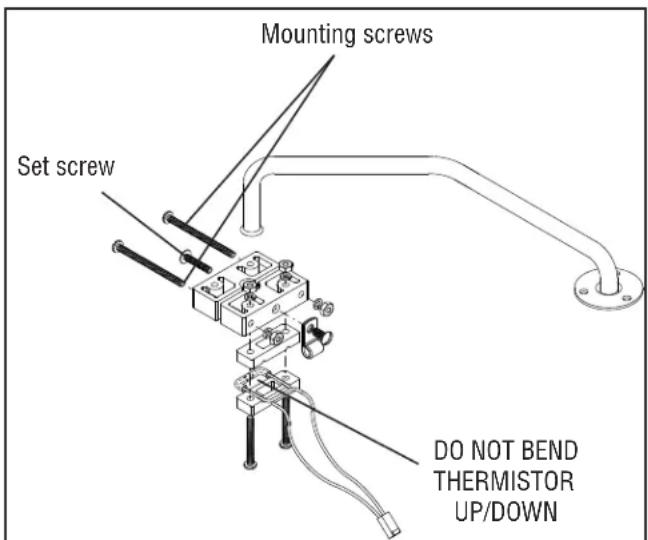
FIG. 17c STEAM SENSOR EXPLODED
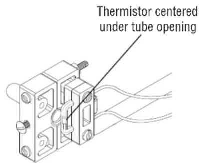
FIG. 17d THERMISTOR POSITION
SERVICE (cont.)
Dispense Valve (PC & H3 Element Only)
Location:
The Dispense Valve is located behind control panel.
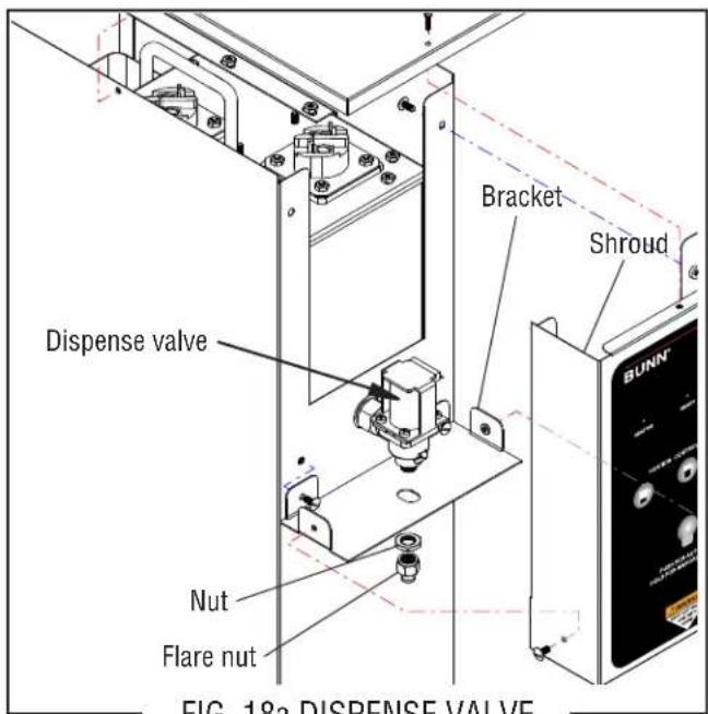
FIG. 18a DISPENSE VALVE
Test Procedures:
- Check the valve for coil action. Turn on the valve with the dispense button. Listen carefully in the vicinity of the dispense valve for a click as the coil pulls the plunger in.
If no sound is heard as described, proceed to #2. If the sound is heard as described, there may be a blockage in the valve. Disconnect the dispenser from the power source. Remove the valve and inspect for blockage, and de-lime all related areas.
- Connect voltmeter leads to the coil terminals. Turn on the valve with the dispense button. NOTE: Due to the internally rectified coil, the indication will be 120VAC all the time. Set the meter to DC volts. The indication should be 170VDC when activated. If the polarity of meter leads are reversed, reading will indicate -170VDC. (Double these readings for 240 volt coils)
If voltage is present as described, but no coil action is observed, valve is defective. Replace valve and test again to verify repair.
If voltage is not present as described, refer to Wiring Diagrams and check the dispenser wiring harness. Also check the control board for proper operation.
Removal and Replacement:
- Disconnect the dispenser from the power source and allow to cool.
- Drain enough water from the tank so the water level is below the outlet.
- Remove the nut and flare nut from the valve.
- Remove the top cover, shroud, and bracket.
- Disconnect wires from the valve.
- Using a back up wrench to hold fitting in place, Remove the valve.
- Wrap threads of fitting with Teflon tape and install new valve.
- Install bracket, nut, flare nut, wires and covers.
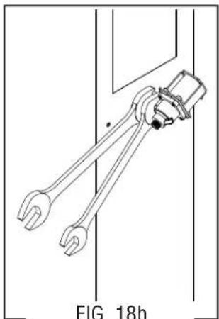
natural_image
Technical line drawing of a mechanical clamp or tool assembly (no text or symbols)VALVE REMOVAL
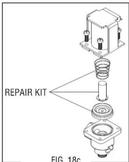
VALVE REPAIR KIT
SERVICE (cont.)
Dispense Valve (PC & H3 Element Only)
Location:
The Dispense Valve is located behind control panel.
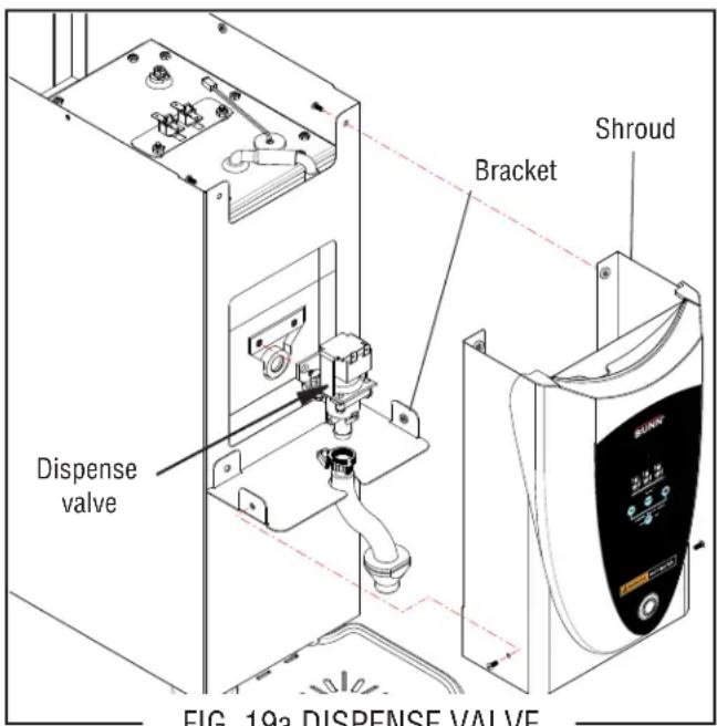
FIG. 19a DISPENSE VALVE
Test Procedures:
- Check the valve for coil action. Turn on the valve with the dispense button. Listen carefully in the vicinity of the dispense valve for a click as the coil pulls the plunger in.
If no sound is heard as described, proceed to #2.
If the sound is heard as described, there may be a blockage in the valve. Disconnect the dispenser from the power source. Remove the valve and inspect for blockage, and de-lime all related areas.
- Connect voltmeter leads to the coil terminals. Turn on the valve with the dispense button. Set the meter to AC volts. The indication should be line voltage when activated.
If voltage is present as described, but no coil action is observed, valve is defective. Replace valve and test again to verify repair.
If voltage is not present as described, refer to Wiring Diagrams and check the dispenser wiring harness. Also check the control board for proper operation.
Removal and Replacement:
- Disconnect the dispenser from the power source and allow to cool.
- Drain enough water from the tank so the water level is below the outlet.
- Remove the top cover (3 screws) and front shroud (4 screws).
- Loosen snap clamp and remove silicon dispense nozzle.
- Remove the two screws securing the valve.
- Disconnect wires from the valve.
- Pull the valve straight out of its grommet.
- Install new valve into grommet.
- Install two screws to secure valve.
- Connect wires.
- Reinstall covers.

natural_image
Technical line drawing of a mechanical assembly with mounting bracket and housing (no text or symbols)VALVE REMOVAL
SERVICE (cont.)
Dispense Switch (H3E Element Only)
Location:
The dispense switch is located in the control panel.
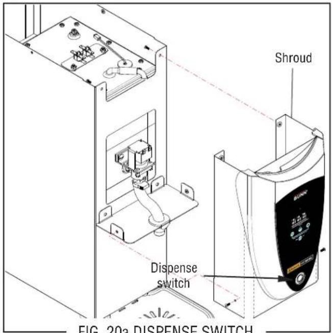
FIG. 20a DISPENSE SWITCH
Removal and Replacement:
- Disconnect the dispenser from the power source.
- Remove the top cover (3 screws) and front shroud assembly (4 screws).
- Remove the top 2 screws and loosen 2 lower screws securing control panel to shroud.
- Disconnect switch wires from the CBA.
- Remove the large nut securing the switch.
- Installation in the reverse order.
Test Procedures:
See disassembly procedure above.
- Disconnect the switch harness from CBA.
- Connect ohmmeter leads to the white and black terminials. There should be continuity when switch is pushed in.
- Connect ohmmeter red lead to the red wire (+) and black lead to tan wire (-). Select the various resistance/continuity or diode scales to see if the LED glows from the meter's battery power source.
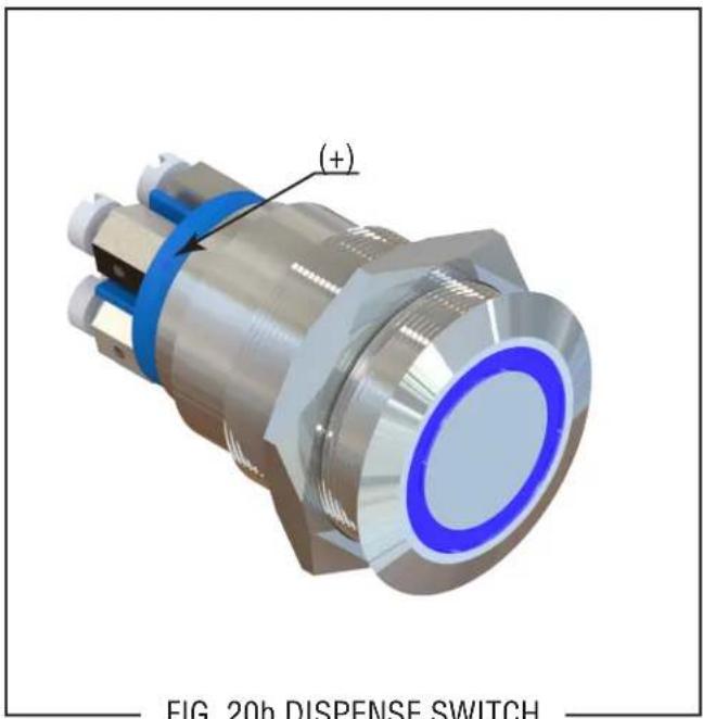
FIG. 20b DISPENSE SWITCH
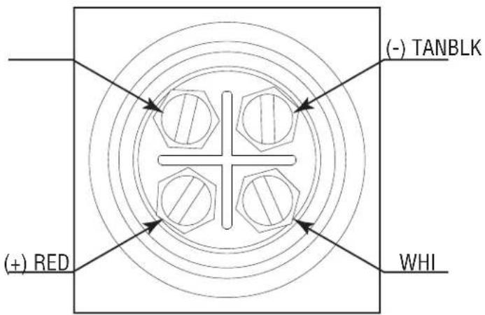
FIG. 20c SWITCH TERMINALS
SERVICE (cont.)
Thermostat (H5M, HW2 & OHW Only)
Location: The mechanical thermostat is located inside the upper rear panel. To test the thermostat, access will also be needed to the terminal block located inside the bottom access panel.
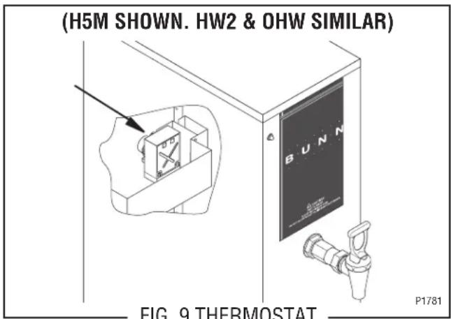
Test Procedure:
- Disconnect the dispenser from the power source.
- Check the voltage across the black wire on the thermostat and the white or red wire at the terminal block with a voltmeter. Connect the dispenser to the power source. The indication must be:
a.) 100 to 120 volts ac for 100 to 120 volt models,
b.) 200 to 240 volts ac for 200 to 240 volt models,
c.) 230 volts ac for 230 volt models. - Disconnect the dispenser from the power source.
If voltage is present as described, proceed to #4. If voltage is not present as described, refer to the Wiring Schematics and check the dispenser wiring harness.
-
Check the voltage across the blue/black wire on the thermostat and the white or red wire at the terminal block with a voltmeter when the thermostat is turned "ON" (fully clockwise). Connect the dispenser to the power source. The indication must be as described in step 2. Voltage must not be indicated when the thermostat is turned "OFF" (fully counterclockwise).
-
Disconnect the dispenser from the power source.
If voltage is present as described, the thermostat is operating properly.
If voltage is not present as described, replace the thermostat.
Removal and Replacement:
- Remove both wires from the thermostat terminals.
- Remove the top lid from the dispenser to gain access to the thermostat bulb.
- Remove the thermostat bulb by firmly pulling up on the capillary tube at the tank. This will disengage the grommet from the tank.
- Remove the two #6-32 screws holding the thermostat to the mounting bracket.
- Fasten the new thermostat to the mounting bracket.
NOTE: Make sure that the capillary tube is away from any electrical termination and is not kinked.
- Slide the grommet to the red mark on the capillary tube.
- Insert the bulb through the hole in the tank and press the grommet firmly and evenly so that the groove in the grommet fits into the tank.
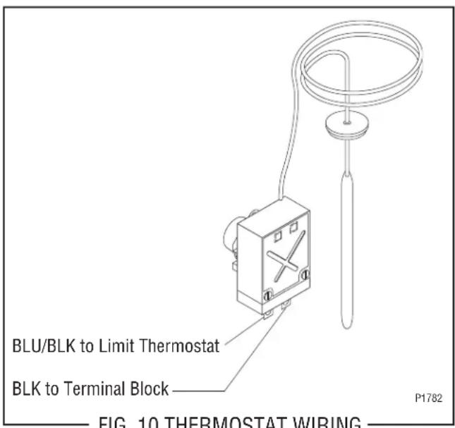
- Refer to FIG. 10 when reconnecting the wires.
- Readjust the thermostat dial as required.
SERVICE (cont.)
Contactor (H5M Only)
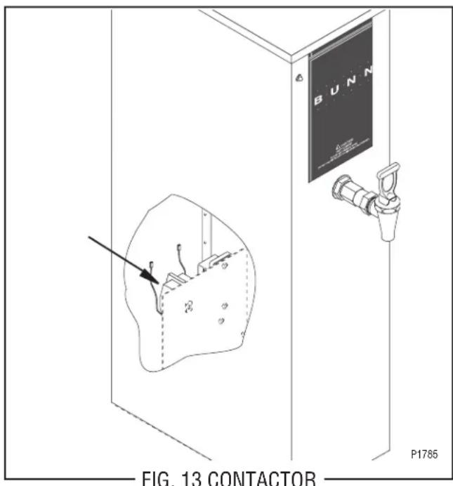
Location:
The contactor is located on the component bracket inside the lower rear panel.
Test Procedures:
- Disconnect the dispenser from the power source.
- Disconnect the black wire from the contactor coil to the limit thermostat and black wire from the red wire on the main harness on two wire 240V models.
- Check the voltage across the red wire and black wire with a voltmeter. The indication must be:
a.) 240 volts ac for 240 volt models,
b.) 230 volts ac for 230 volt models. - Disconnect the dispenser from the power source.
If voltage is present as described, proceed to #5.
If voltage is not present as described refer to the Wiring Diagrams and check the wiring harness.
- Check for continuity between the left and right terminals on the contactor coil.
If continuity is present as described, reconnect the wires and proceed to #6
If continuity is not present as described, replace the contactor.
- Check the voltage across the upper left terminal and the upper right terminal on the contactor with a voltmeter. Connect the dispenser to the power source. The indication must be:
a.) 240 volts ac for 240 volt models,
b.) 230 volts ac for 230 volt models.
- Disconnect the dispenser from the power source.
If voltage is present as described, proceed to #8.
If voltage is not present as described, refer to the wiring diagrams and check the wiring harness.
- Check for continuity across the terminals on the left side of the contactor by manually closing the contacts. Continuity must not present when the contact is released.
- Check for continuity across the terminals on the right side of the contactor by manually closing the contacts. Continuity must not be present when the contact is released.
If continuity is present as described, the contactor is operating properly.
If continuity is not present as described, replace the contactor.
SERVICE (cont.)
Liquid Level Board (H5M & HW2 Only)
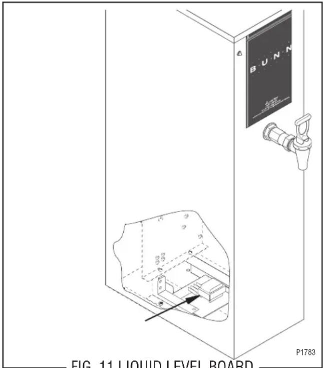
FIG. 11 LIQUID LEVEL BOARD
Location:
The liquid level board is located inside the lower panel.
Test Procedure:
- Disconnect the dispenser from the power source.
- Remove the blue wire from terminal 1 and the pink wire from terminal 4 of the circuit board.
- Check the voltage across terminals 2 and 3 with a voltmeter. Connect the dispenser to the power source. Turn the thermostat knob to the "ON" position (fully clockwise). The indication must be:
a.) 100 to 120 volts ac for 100 to 120 volt models,
b.) 200 to 240 volts ac for 200 to 240 volt models,
c.) 230 volts ac for 230 volt models.
- Disconnect the dispenser from the power source.
If voltage is present as described, proceed to #5.
If voltage is not present as described, refer to the wiring diagrams and check the wiring harness.
- Reconnect the blue wire to terminal 1.
- Carefully connect a piece of insulated jumper wire to terminal 4. Keep the other end of this wire away
from any metal surface of the dispenser.
- Check the voltage across terminals 1 & 3 with a voltmeter. Connect the dispenser to the power source. Turn the thermostat knob to the "ON" position (fully clockwise). The indication must be:
a.) 100 to 120 volts ac for 100 to 120 volt models,
b.) 200 to 240 volts ac for 200 to 240 volt models,
c.) 230 volts ac for 230 volt models, after a delay of approximately 5 seconds.
- Touch the free end of jumper wire to the dispenser housing. The indication must be 0.
- Move the jumper wire away from the dispenser housing. The indication must again be:
a.) 100 to 120 volts ac for 100 to 120 volt models,
b.) 200 to 240 volts ac for 200 to 240 volt models,
c.) 230 volts ac for 230 volt models, after a delay of approximately 5 seconds.
- Disconnect the dispenser from the power source and remove the jumper wire from terminal 4.
If voltage is present as described, the level control board is operating properly, proceed to #11.
If voltage is not present as described, replace the level control board.
- Reconnect the pink wire to terminal 4.
- Gently pull the probe out of the tank and inspect for corrosion. Replace it if necessary.
- Place the probe so that neither end is in contact with any metal surface of the dispenser.
- Check the voltage across terminals 1 & 3 with a voltmeter. Connect the dispenser to the power source. Turn the thermostat knob to the "ON" position (fully clockwise). The indication must be:
a.) 100 to 120 volts ac for 100 to 120 volt models,
b.) 200 to 240 volts ac for 200 to 240 volt models,
c.) 230 volts ac for 230 volt models, after a delay of approximately 5 seconds.
SERVICE (cont.)
Liquid Level Board (cont.) (H5M & HW2 Only)
- Move the probe's flat end to the dispenser housing. The indication must be 0.
- Move the probe's flat end away from the dispenser housing. The indication should again be:
a.) 100 to 120 volts ac for 100 to 120 volt models,
b.) 200 to 240 volts ac for 200 to 240 volt models,
c.) 230 volts ac for 230 volt models. - Disconnect the dispenser from the power source.
If voltage is present as described, reinstall the probe, the level control board and level probe are operating properly.
If voltage is not present as described, check the pink probe wire.
Removal and Replacement:
-
Remove all wires from the level control board.
-
Remove two #8-32 screws holding level control board and mounting bracket to the component bracket.
- Install the new level control board and mounting bracket to the component bracket.
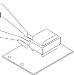
- Refer to FIG. 12 when reconnecting the wires.
BLU to Solenoid (T-1)
BLK to Overflow Safety Switch (T-2)
WHI to Terminal Block (T-3)
PNK to Level Probe (T-4)
natural_image
Pure technical line drawing of a mechanical assembly with no text or symbolsP1784
FIG. 12 LIQUID LEVEL BOARD WIRING
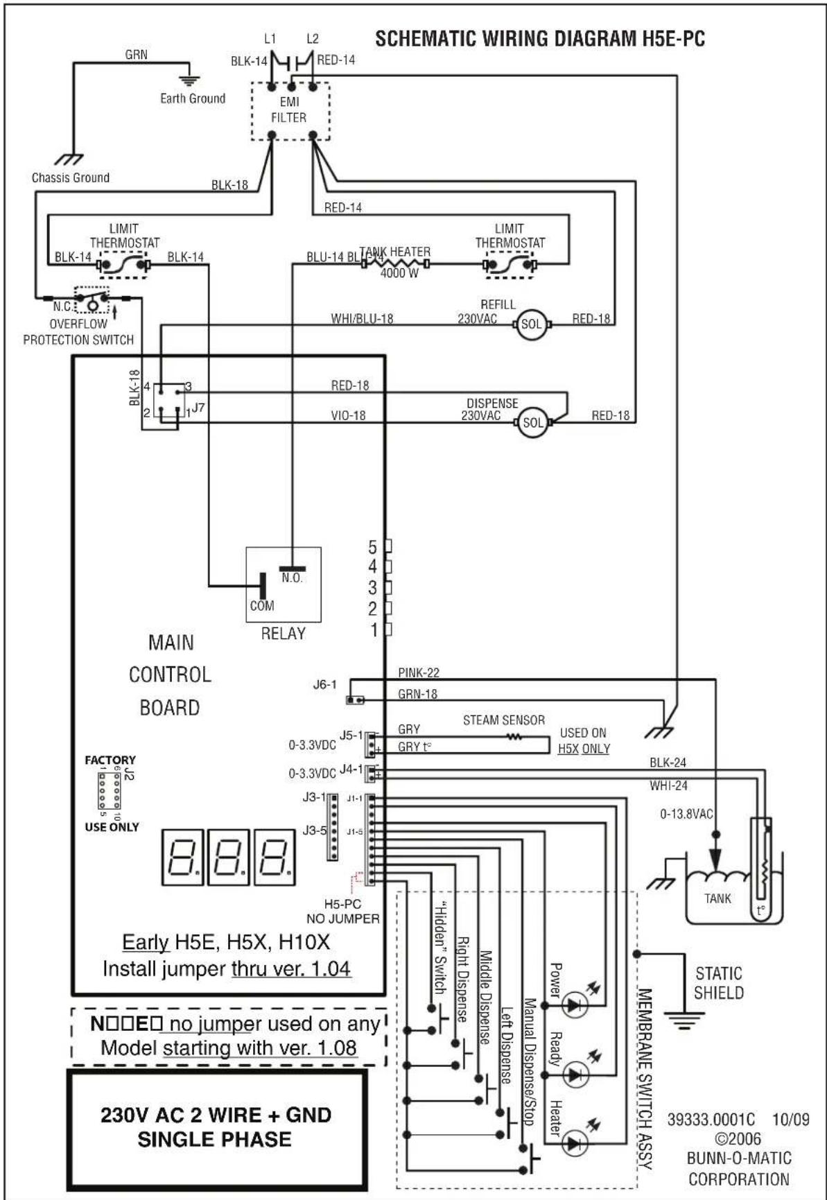
flowchart
graph TD
    A["MAIN CONTROL BOARD"] --> B["CHASSIS GROUND"]
    B --> C["GRN"]
    B --> D["Earth Ground"]
    B --> E["L1"]
    B --> F["L2"]
    B --> G["RED-14"]
    B --> H["EMI FILTER"]
    B --> I["BLK-18"]
    I --> J["RED-14"]
    J --> K["BLK-14"]
    K --> L["LIMIT THERMOSTAT BLK-14"]
    L --> M["N.C. OVERFLOW PROTECTION SWITCH"]
    M --> N["J7"]
    N --> O["BLK-18"]
    O --> P["RED-18"]
    P --> Q["VIO-18"]
    Q --> R["DISPENSE 230VAC SOL"]
    R --> S["RED-18"]
    S --> T["WHI/BLU-18"]
    T --> U["REFILL 230VAC SOL"]
    U --> V["SOL"]
    V --> W["RED-18"]
    W --> X["BRIDGE"]
    X --> Y["COM RELAY"]
    Y --> Z["N.O."]
    Z --> AA["BLK-18"]
    AA --> AB["RED-14"]
    AB --> AC["BLU-14 BLTANK HEATER 4000 W"]
    AC --> AD["LIMIT THERMOSTAT"]
    AD --> AE["WHI/BLU-18"]
    AE --> AF["SOL"]
    AF --> AG["RED-18"]
    AG --> AH["SOL"]
    AH --> AI["SOL"]
    AI --> AJ["SOL"]
    AJ --> AK["SOL"]
    AK --> AL["SOL"]
    AL --> AM["SOL"]
    AM --> AN["SOL"]
    AN --> AO["SOL"]
    AO --> AP["SOL"]
    AP --> AQ["SOL"]
    AQ --> AR["SOL"]
    AR --> AS["SOL"]
    AS --> AT["SOL"]
    AT --> AU["SOL"]
    AU --> AV["SOL"]
    AV --> AW["SOL"]
    AW --> AX["SOL"]
    AX --> AY["SOL"]
    AY --> AZ["SOL"]
    AZ --> BA["SOL"]
    BA --> BB["SOL"]
    BB --> BC["SOL"]
    BC --> BD["SOL"]
    BD --> BE["SOL"]
    BE --> BF["SOL"]
    BF --> BG["SOL"]
    BG --> BH["SOL"]
    BH --> BI["SOL"]
    BI --> BJ["SOL"]
    BJ --> BK["SOL"]
    BK --> BL["SOL"]
    BL --> BM["SOL"]
    BM --> BN["SOL"]
    BN --> BO["SOL"]
    BO --> BP["SOL"]
    BP --> BQ["SOL"]
    BQ --> BR["SOL"]
    BR --> BS["SOL"]
    BS --> BT["SOL"]
    BT --> BU["SOL"]
    BU --> BV["SOL"]
    BV --> BW["SOL"]
    BW --> BX["SOL"]
    BX --> BY["SOL"]
    BY --> BZ["SOL"]
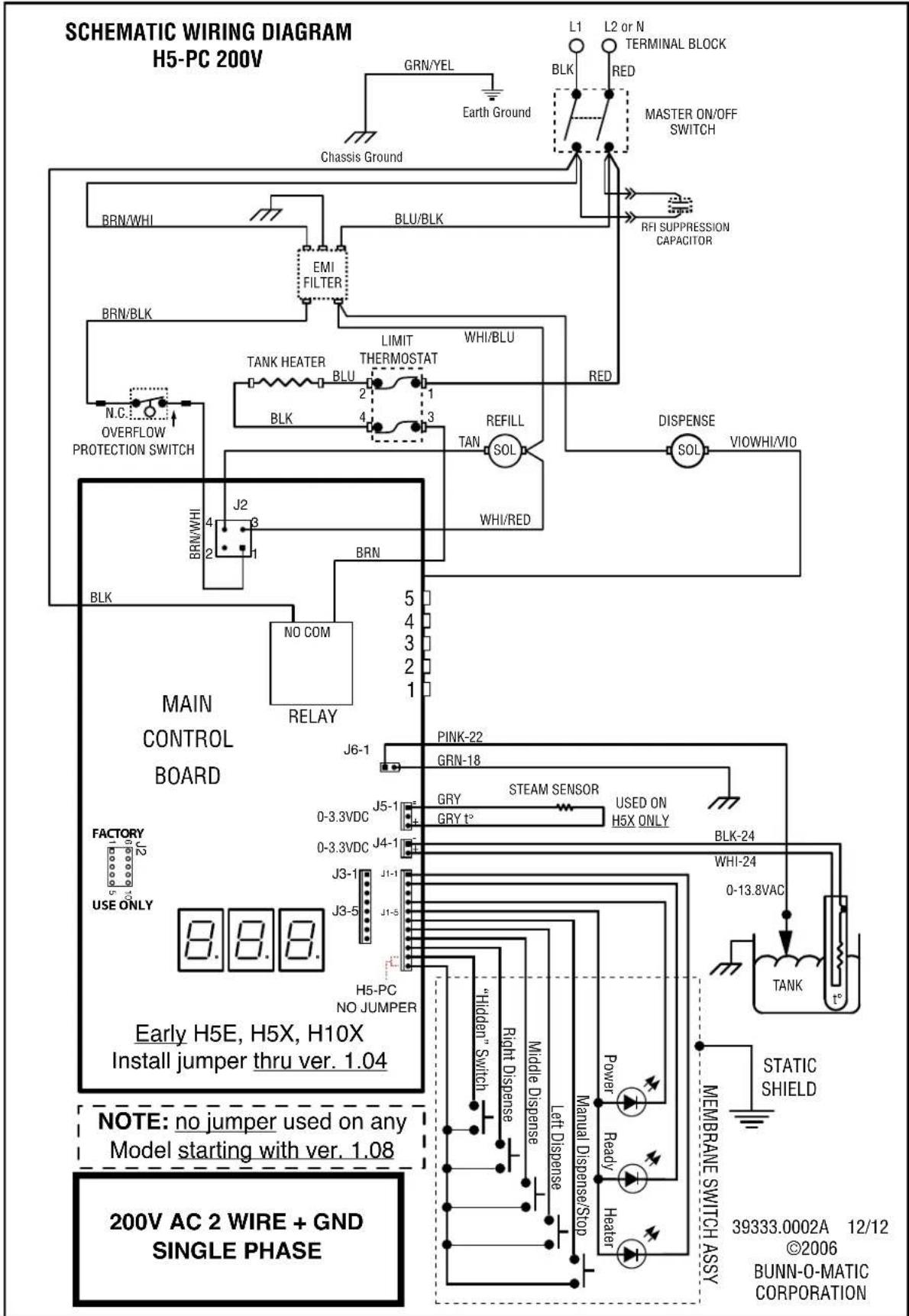
flowchart
graph TD
    A["SCHEMATIC WIRING DIAGRAM H5-PC 200V"] --> B["MAIN CONTROL BOARD"]
    B --> C["Factory USE ONLY"]
    C --> D["Early H5E, H5X, H10X Install jumper thru ver. 1.04"]
    D --> E["NOTE: no jumper used on any Model starting with ver. 1.08"]
    E --> F["200V AC 2 WIRE + GND SINGLE PHASE"]

    subgraph Control Board
        G["BRN/WHI"] --> H["BLU/BLK"]
        I["EMI FILTER"] --> J["BLT"]
        K["TANK HEATER BLU"] --> L["REFILL SOL"]
        M["N.C. OVERFLOW PROTECTION SWITCH"] --> N["BLK"]
        O["J2"] --> P["NO COM RELAY"]
        Q["BRN"] --> R["BLK"]
        S["PINK-22 GRN-18"] --> T["J6-1"]
        U["GRY GRY t°"] --> V["J5-1"]
        W["STEAM SENSOR USED ON H5X ONLY"] --> X["J4-1"]
        Y["Manual Dispense/Stop"] --> Z["H5-PC NO JUMPER"]
        AA["THEDEN Switch"] --> AB["Right Dispense"]
        AC["Middle Dispense"] --> AD["Left Dispense"]
        AE["Power Ready Heater"] --> AF["HEATER"]
        AG["STATIC SHIELD"] --> AH["TANK"]
    end

    subgraph Control Panel
        AI["L1 L2 or N TERMINAL BLOCK"] --> AJ["Master ON/OFF SWITCH"]
        AK["RFI SUPPRESSION CAPACITOR"] --> AL["DISPENSE SOL"]
        AM["BLK"] --> AN["Ground"]
        AO["BLK"] --> AP["Ground"]
        AQ["BLK"] --> AR["Ground"]
        AS["RED"] --> AT["Red"]
        AU["WHI/BLU"] --> AV["Limit Thermostat"]
        AW["WHI/RED"] --> AX["WHI/RED"]
    end
SCHEMATIC WIRING DIAGRAM H10X
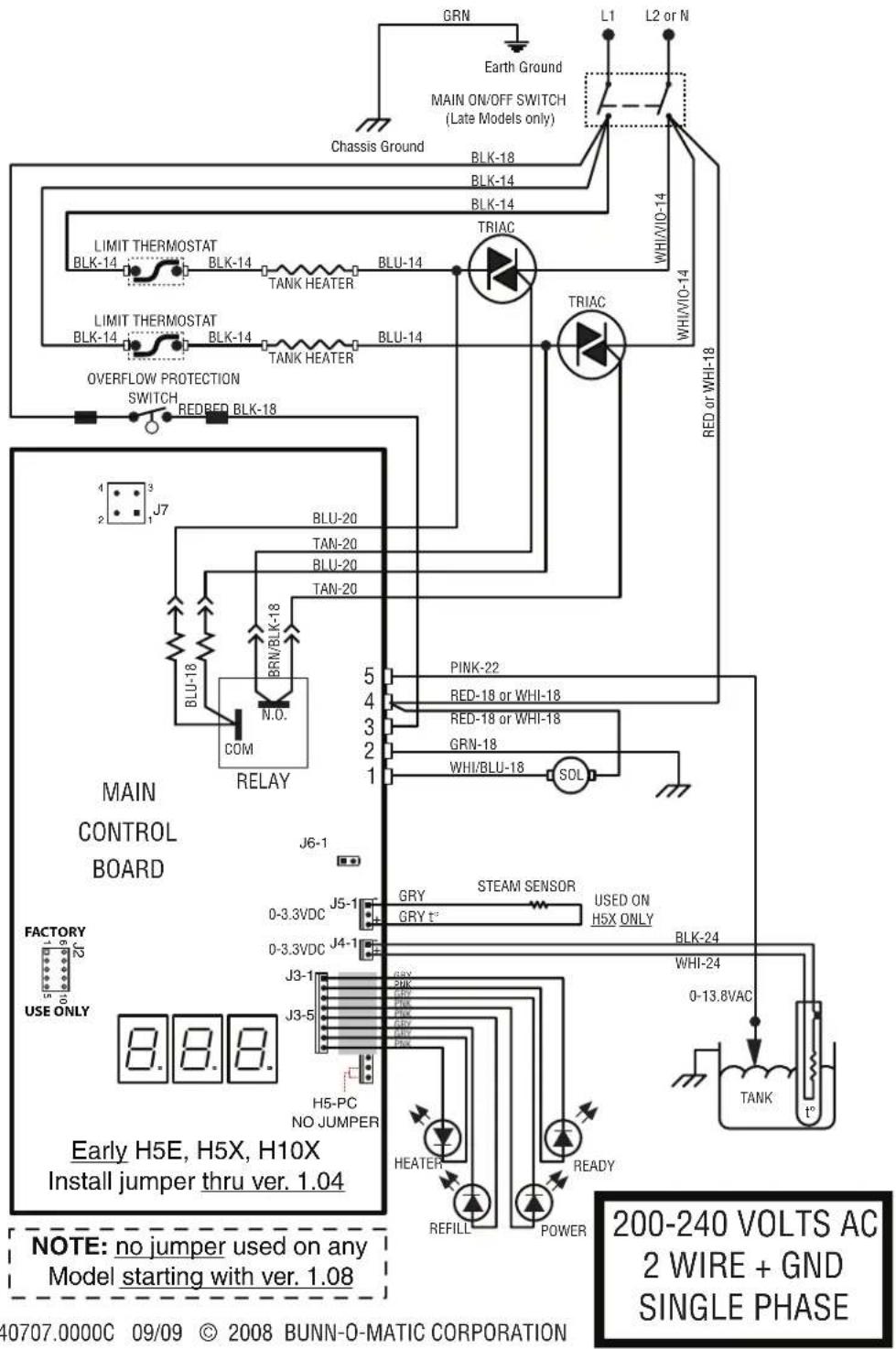
SCHEMATIC WIRING DIAGRAM H5E/H5X
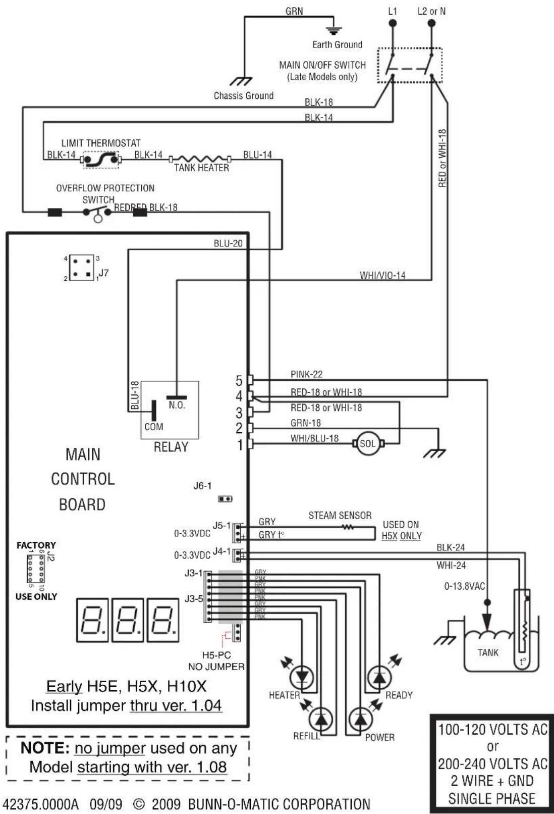
SCHEMATIC WIRING DIAGRAM H5XA, H5EA (CE)
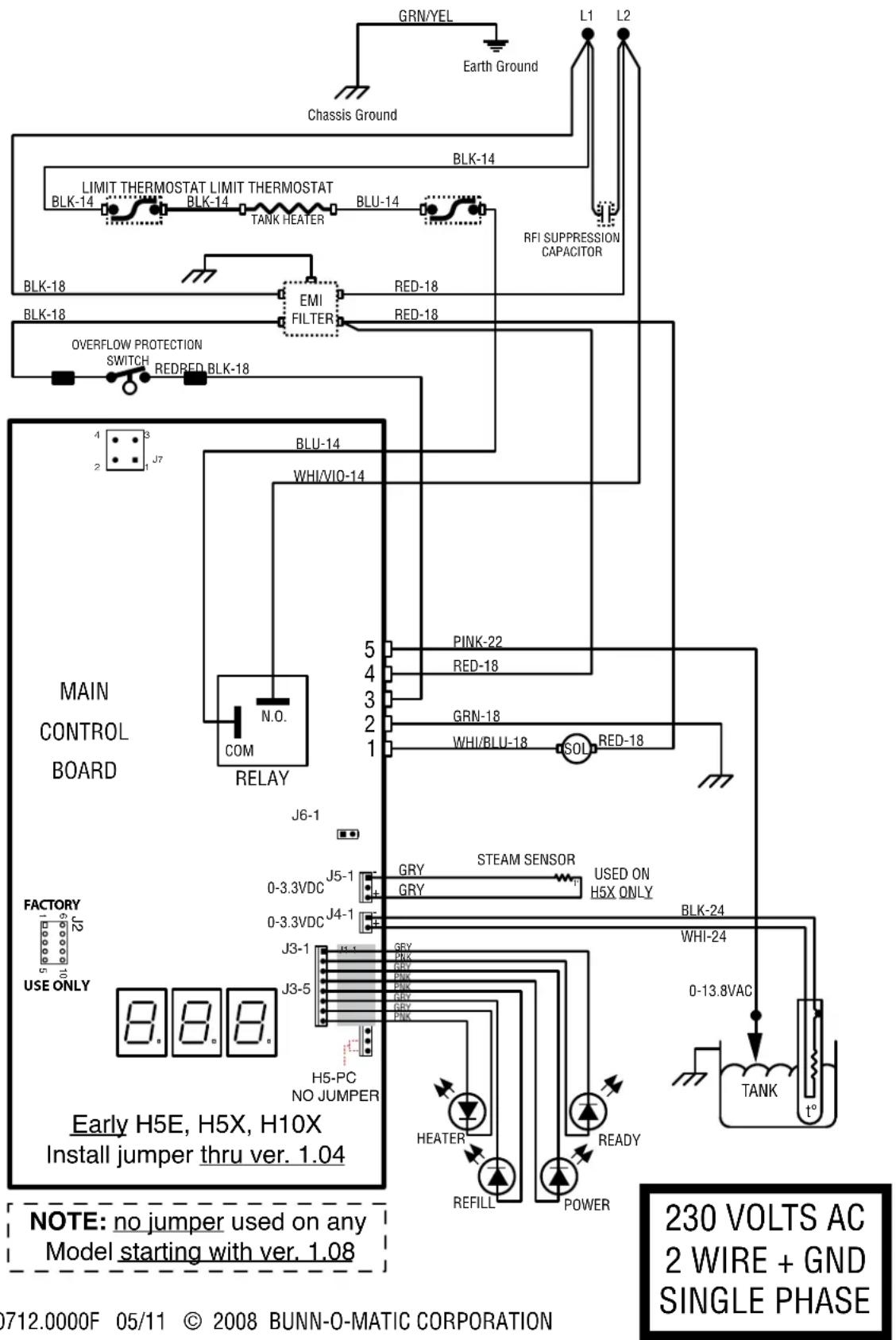
40712.0000F 05/11 © 2008 BUNN-O-MATIC CORPORATION
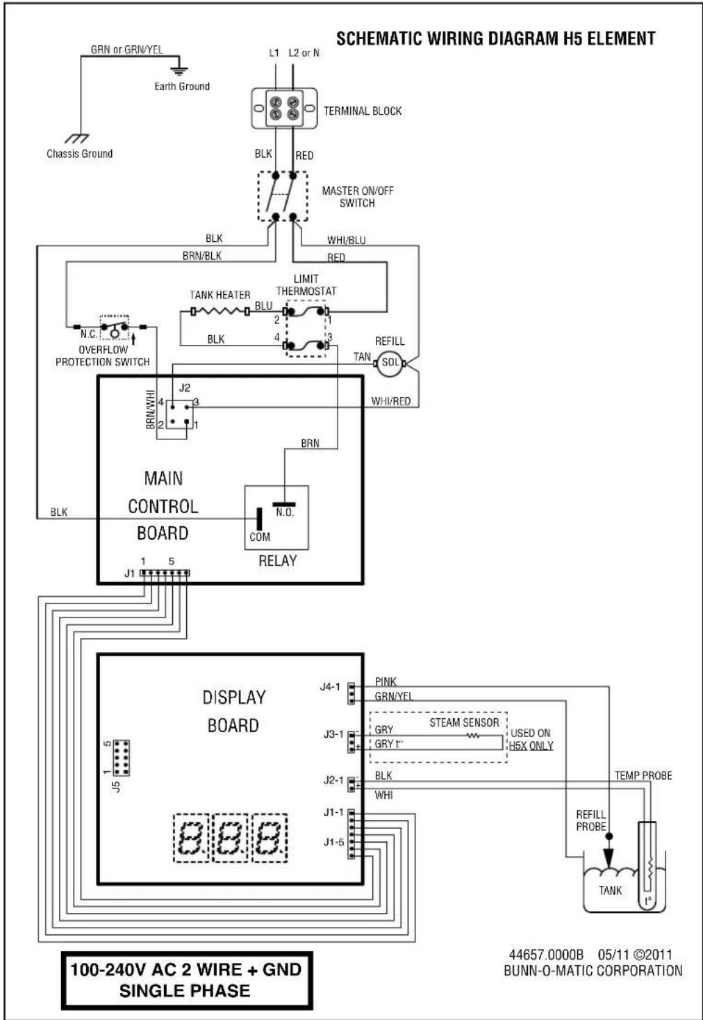
flowchart
graph TD
    A["CHassis Ground"] --> B["GRN or GRN/YEL"]
    B --> C["Earth Ground"]
    C --> D["L1 L2 or N"]
    D --> E["TERMINAL BLOCK"]
    E --> F["BLK RED"]
    F --> G["MASTER ON/OFF SWITCH"]
    G --> H["BRN/BLK RED"]
    H --> I["TANK HEATER BLU"]
    I --> J["LIMIT THERMOSTAT"]
    J --> K["BLK 2 1"]
    K --> L["REFILL SOL"]
    L --> M["TAN 3"]
    M --> N["WHI/RED"]
    N --> O["MAIN CONTROL BOARD"]
    O --> P["N.O. COM"]
    P --> Q["RELAY"]
    Q --> R["J1 5"]
    R --> S["DISPLAY BOARD"]
    S --> T["J4-1 PINK GRN/YEL"]
    S --> U["J3-1 GRY STEAM SENSOR GRY t" USED ON H5X ONLY"]
    S --> V["J2-1 BLK WHI"]
    S --> W["J1-1 J1-1"]
    S --> X["J1-5 J1-5"]
    T --> Y["TANK TEMP PROBE"]
    U --> Y
    V --> Y
    W --> Y
    X --> Y
    style A fill:#f9f,stroke:#333
    style Y fill:#ccf,stroke:#333
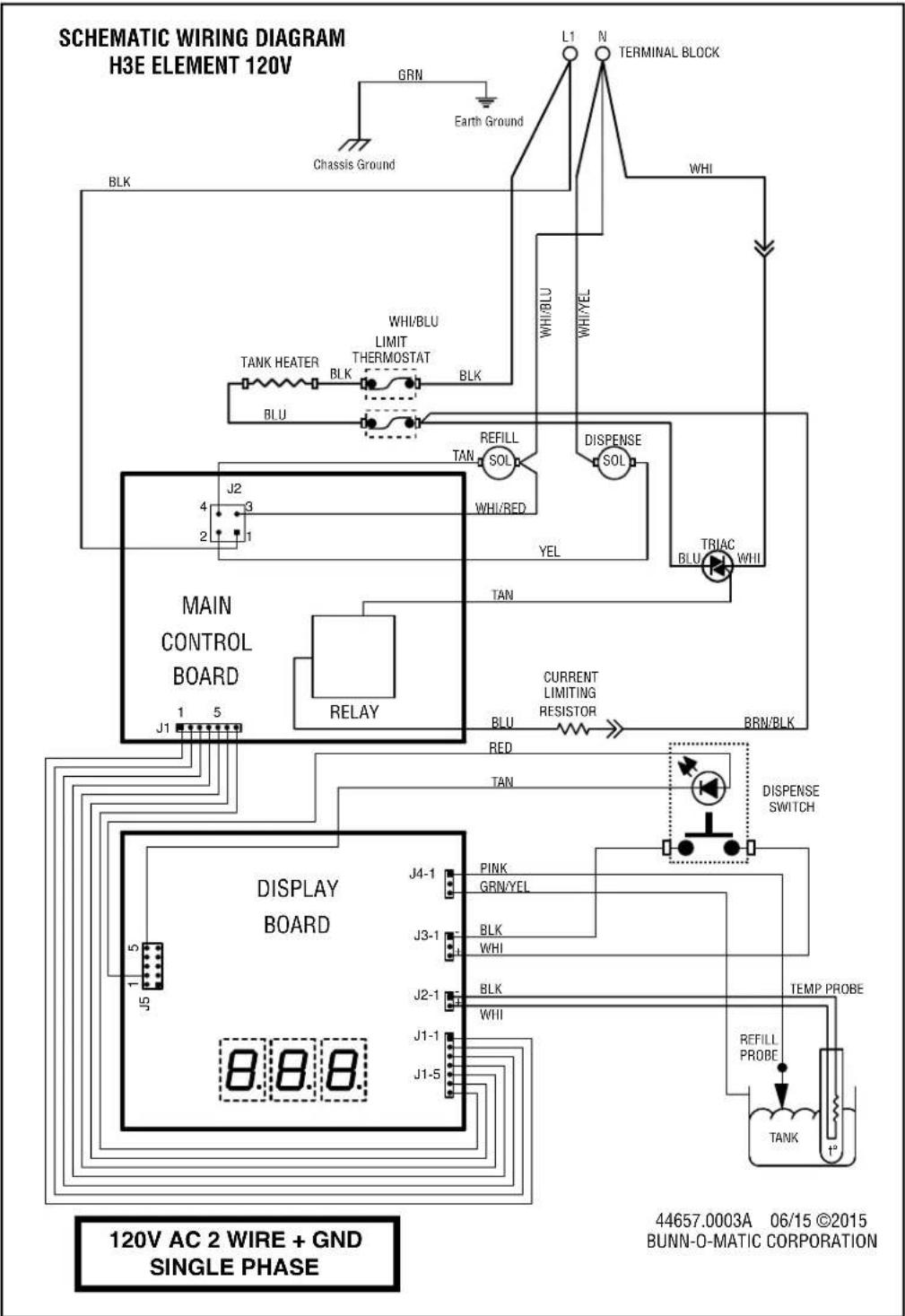
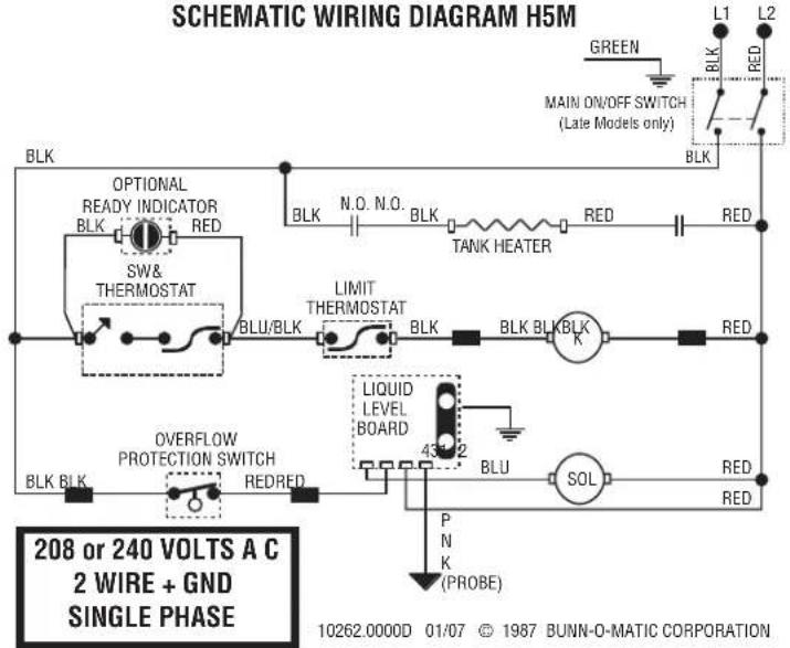
SCHEMATIC WIRING DIAGRAM H5M
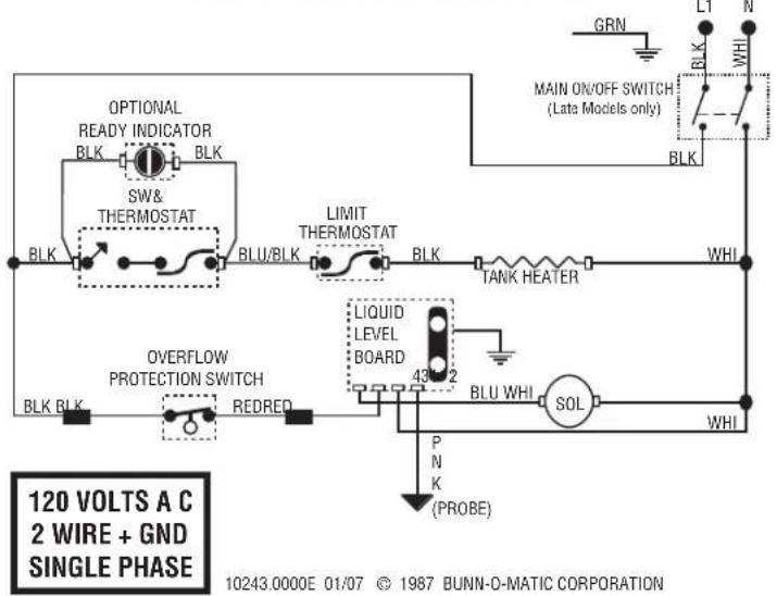
SCHEMATIC WIRING DIAGRAM H5M
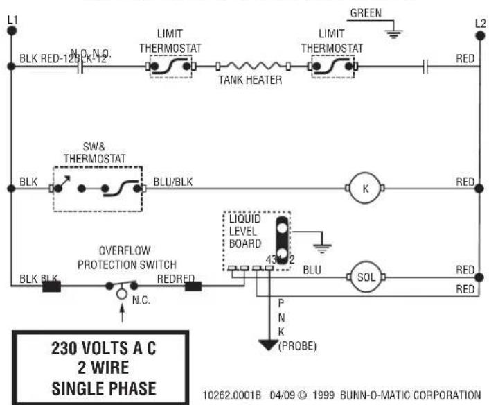
SCHEMATIC WIRING DIAGRAM H5MA, 230V CE
SCHEMATIC WIRING DIAGRAM HW2
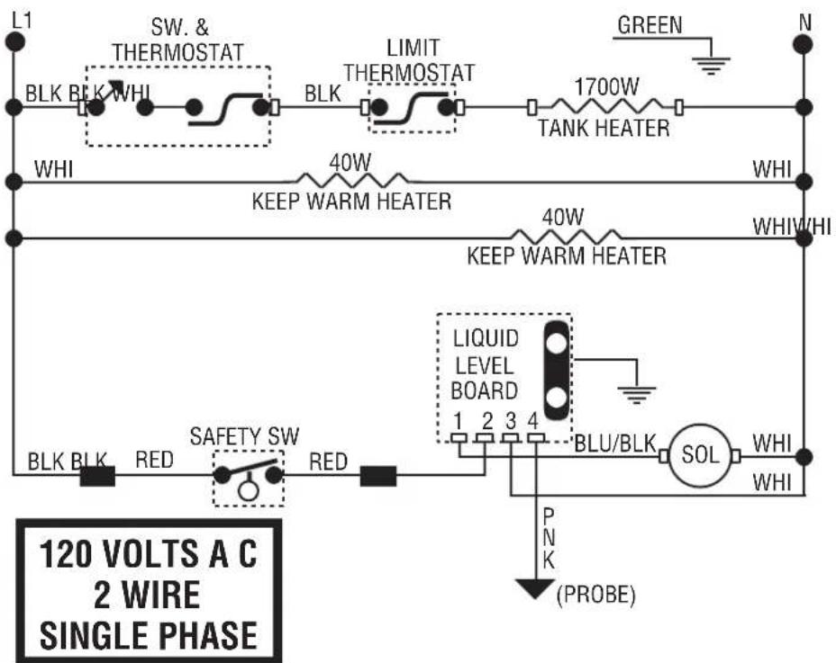
10261.0000E 5/98 © 1987 BUNN-O-MATIC CORPORATION
SCHEMATIC WIRING DIAGRAM HW2A
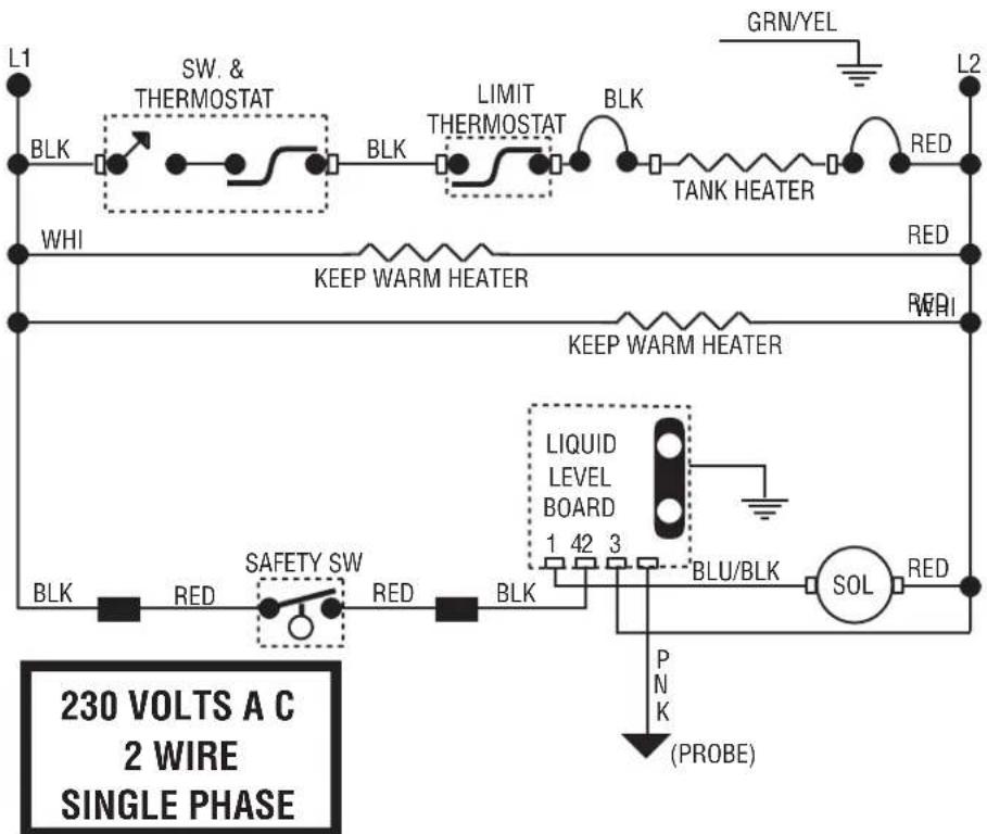
10261.0001G 05/09 © 1998 BUNN-O-MATIC CORPORATION
SCHEMATIC WIRING DIAGRAM OHW
120 VOLTS A C
2 WIRE
SINGLE PHASE
60 HZ
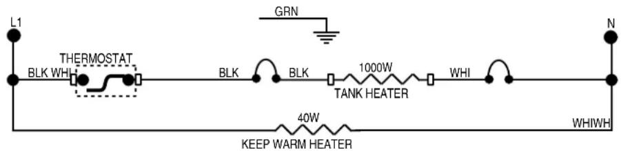
10269.0000B 6/98 © 1988 BUNN-O-MATIC CORPORATION
SCHEMATIC WIRING DIAGRAM OHWA
230 VOLTS A C
2 WIRE
SINGLE PHASE
50 HZ
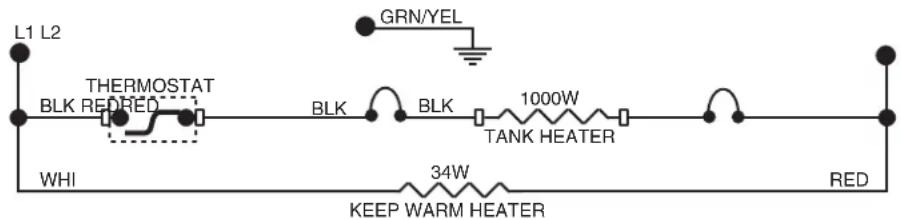
10269.0001C 04/09 © 1998 BUNN-O-MATIC CORPORATION
- SERVICE MANUAL
- BUNN-O-MATIC CORPORATION
- BUNN-O-MATIC COMMERCIAL PRODUCT WARRANTY
- CONTENTS
- TROUBLESHOOTING
- WARNING
- Problem
- Probable Cause
- Remedy
- TROUBLESHOOTING (cont.)
- SERVICE
- BOARD AND TRIAC
- Location:
- General:
- Liquid Level Control Flow Charts
- SERVICE (cont.)
- Electronic Controls (cont.)
- Liquid Level Control Test Procedure
- Temperature Control Flow Charts
- H5/10X THERMOSTAT H3/5E THERMOSTAT
- Temperature Control Flow Charts (cont.)
- Temperature Control Test Procedure
- Electronic Controls Removal and Replacement
- Adjustments
- Limit Thermostat
- Test Procedure:
- Removal and Replacement:
- Solenoid Valve (Late Models)
- Solenoid Valve (Early Models)
- Tank Heater
- Steam Sensor (Thermistor)
- Dispense Valve (PC & H3 Element Only)
- Test Procedures:
- Dispense Switch (H3E Element Only)
- Thermostat (H5M, HW2 & OHW Only)
- Contactor (H5M Only)
- Liquid Level Board (cont.) (H5M & HW2 Only)
Brand : Bunn
Model : H5X Element SST
Category : Water dispenser