
H3X Element - Water dispenser Bunn - Free user manual and instructions
Find the device manual for free H3X Element Bunn in PDF.


| Product Type | Hot Water Dispenser |
| Model | H3X Element |
| Brand | Bunn |
| Water Capacity | 3 gallons (11.4 L) |
| Dimensions (Approx.) | 12.25 x 8.5 x 18.5 in (311 x 216 x 470 mm) |
| Net Weight (Approx.) | 18 lbs (8.2 kg) |
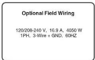
| Power Supply | 120/208-240V AC, 16.9A, 4050W, 1PH, 3-Wire + GND, 60Hz (optional field wiring) |
| Power Cord | 120V AC models: 2-wire + GND; 120/208-240V models: 3-wire + GND |
| Water Supply | Cold water, 20-90 psi (0.138-0.620 mPa), 1/4" flare inlet (CE/UK: 3/4" BSP on H3EA) |
| Temperature Range | Set: 60°F to 211°F (15°C to 99°C); Ready: 2°F to 20°F below set temp |
| Factory Temperature | 200°F (93.3°C) for standard altitude |
| Heater Type | Internal tank with thermostat |
| Display | Digital with temperature readout and model indication |
| Controls | Hidden programming button, + and - buttons, SET/LOCK switch |
| Programmable Features | Set temperature, ready temperature, energy saver mode (auto/manual), dispense lockout |
| Energy Saver Mode | Drops tank temp to 140°F (60°C) or heater off, with adjustable delay (4-24 hours) |
| Dispensing | Continuous flow (push and hold) or optional portion control (P7 setting) |
| Materials | Stainless steel tank and exterior |
| Installation | Countertop or wall-mountable (bracket kits available) |
| Cleaning | Damp cloth with mild detergent; do not immerse or use pressure washer |
| Warranty | 2 years parts and 1 year labor (electronics: 3 years parts/labor); excludes misuse, poor water quality |
| Safety | Heated when connected; hot water warning; overheat protection |
| Standards | CE and North American requirements; IP20 (indoor use) |
Frequently Asked Questions - H3X Element Bunn
User questions about H3X Element Bunn
0 question about this device. Answer the ones you know or ask your own.
Ask a new question about this device
Download the instructions for your Water dispenser in PDF format for free! Find your manual H3X Element - Bunn and take your electronic device back in hand. On this page are published all the documents necessary for the use of your device. H3X Element by Bunn.
USER MANUAL H3X Element Bunn
BUNN-O-MATIC CORPORATION
To ensure you have the latest revision of the manual or to obtain the illustrated parts catalog, please visit the Bunn-O-Matic website, at www.bunn.com. This is absolutely FREE, and the quickest way to obtain the latest catalog and manual updates. Contact Bunn-O-Matic Corporation at 1-800-286-6070 to obtain a paper copy of the required Illustrated Parts Catalog mailed via U.S. Postal Service.
BUNN-O-MATIC COMMERCIAL PRODUCT WARRANTY
Bunn-O-Matic Corp. ("BUNN") warrants equipment manufactured by it as follows:
1) Airpots, thermal carafes, decanters, GPR servers, iced tea/coffee dispensers, MCR/MCP/MCA single cup brewers, thermal servers and ThermoFresh® servers (mechanical and digital) 1 year parts and 1 year labor.
2) All other equipment - 2 years parts and 1 year labor plus added warranties as specified below:
a) Electronic circuit and/or control boards - parts and labor for 3 years.
b) Compressors on refrigeration equipment - 5 years parts and 1 year labor.
c) Grinding burrs on coffee grinding equipment to grind coffee to meet original factory screen sieve analysis - parts and labor for 4 years or 40,000 pounds of coffee, whichever comes first.
These warranty periods run from the date of installation BUNN warrants that the equipment manufactured by it will be commercially free of defects in material and workmanship existing at the time of manufacture and appearing within the applicable warranty period. This warranty does not apply to any equipment, component or part that was not manufactured by BUNN or that, in BUNN's judgment, has been affected by misuse, neglect, alteration, improper installation or operation, improper maintenance or repair, non periodic cleaning and descaling, equipment failures related to poor water quality, damage or casualty. In addition, the warranty does not apply to replacement of items subject to normal use including but not limited to user replaceable parts such as seals and gaskets. This warranty is conditioned on the Buyer 1) giving BUNN prompt notice of any claim to be made under this warranty by telephone at (217) 529-6601 or by writing to Post Office Box 3227, Springfield, Illinois 62708-3227; 2) if requested by BUNN, shipping the defective equipment prepaid to an authorized BUNN service location; and 3) receiving prior authorization from BUNN that the defective equipment is under warranty.
THE FOREGOING WARRANTY IS EXCLUSIVE AND IS IN LIEU OF ANY OTHER WARRANTY, WRITTEN OR ORAL, EXPRESS OR IMPLIED, INCLUDING, BUT NOT LIMITED TO, ANY IMPLIED WARRANTY OF EITHER MERCHANTABILITY OR FITNESS FOR A PARTICULAR PURPOSE. The agents, dealers or employees of BUNN are not authorized to make modifications to this warranty or to make additional warranties that are binding on BUNN. Accordingly, statements by such individuals, whether oral or written, do not constitute warranties and should not be relied upon.
If BUNN determines in its sole discretion that the equipment does not conform to the warranty, BUNN, at its exclusive option while the equipment is under warranty, shall either 1) provide at no charge replacement parts and/or labor (during the applicable parts and labor warranty periods specified above) to repair the defective components, provided that this repair is done by a BUNN Authorized Service Representative; or 2) shall replace the equipment or refund the purchase price for the equipment.
THE BUYER'S REMEDY AGAINST BUNN FOR THE BREACH OF ANY OBLIGATION ARISING OUT OF THE SALE OF THIS EQUIPMENT, WHETHER DERIVED FROM WARRANTY OR OTHERWISE, SHALL BE LIMITED, AT BUNN'S SOLE OPTION AS SPECIFIED HEREIN, TO REPAIR, REPLACEMENT OR REFUND.
In no event shall BUNN be liable for any other damage or loss, including, but not limited to, lost profits, lost sales, loss of use of equipment, claims of Buyer's customers, cost of capital, cost of down time, cost of substitute equipment, facilities or services, or any other special, incidental or consequential damages.
392, A Partner You Can Count On, Air Infusion, AutoPOD, AXIOM, BrewLOGIC, BrewMETER, Brew Better Not Bitter, BrewWISE, BrewWIZARD, BUNN Espress, BUNN Family Gourmet, BUNN Gourmet, BUNN Pour-O-Matic, BUNN, BUNN with the stylized red line, BUNNlink, Bunn-OMatic, Bunn-O-Matic, BUNNserve, BUNNSERVE with the stylized wrench design, Cool Froth, DBC, Dr. Brew stylized Dr. design, Dual, Easy Pour, EasyClear, EasyGard, FlavorGard, Gourmet Ice, Gourmet Juice, High Intensity, iMIX, Infusion Series, Intellisteam, My Café, Phase Brew, PowerLogic, Quality Beverage Equipment Worldwide, Respect Earth, Respect Earth with the stylized leaf and coffee cherry design, Safety-Fresh, savemycoffee.com, Scale-Pro, Silver Series, Single, Smart Funnel, Smart Hopper, SmartWAVE, Soft Heat, SplashGard, The Mark of Quality in Beverage Equipment Worldwide, ThermoFresh, Titan, trifecta, TRIFECTA (sylized logo), Velocity Brew, Air Brew, Beverage Bar Creator, Beverage Profit Calculator, Brew better, not bitter., Build-A-Drink, BUNNSource, Coffee At Its Best, Cyclonic Heating System, Daypart, Digital Brewer Control, Element, Milk Texturing Fusion, Nothing Brews Like a BUNN, Picture Prompted Cleaning, Pouring Profits, Signature Series, Sure Tamp, Tea At Its Best, The Horizontal Red Line, Ultra are either trademarks or registered trademarks of Bunn-O-Matic Corporation. The commercial trifecta® brewer housing configuration is a trademark of Bunn-O-Matic Corporation.
CONTENTS
WARRANTY 2
INTRODUCTION....3
CE & NORTH AMERICA REQUIREMENTS 4
USER NOTICES 5
ELECTRICAL REQUIREMENTS....6
PLUMBING REQUIREMENTS....7
INITIAL SET-UP (H5E, H5X, H5-PC, H3/5 ELEMENT, H10X) 7
INITIAL SET-UP H5M, HW2, OHW 8
OPERATING CONTROLS (H5-PC ONLY)....9
ADJUST DISPENSE VOLUME (H5-PC ONLY) 9
PROGRAMMING (H5E, H5X, H5-PC, H10X) 10
PROGRAMMING (H5 ELEMENT) 12
PROGRAMMING (H3E ELEMENT) 15
DRAINING THE DISPENSER 20
CLEANING....20
WALL MOUNT & SUPPORT 20
INTRODUCTION
This equipment heats and dispenses water on demand for beverages and cooking purposes. It has a panel above the faucet that indicates the status of the dispenser. This equipment is for indoor use, either wall-mounted (H5E/X/PC) or on a sturdy counter or shelf.
| Brew water temperature is factory set at 200° F (93.3° C) Areas of high altitude will require lowering this temperature to prevent boiling. This chart should be used as a guide when readjusting the brew water temperature. | ||
| Altitude(Feet) | Boiling point of water° F °C | Recommended water temperature° F °C |
| -1000 213.8 101.0 200 93.3 | ||
| -500 212.9 100.5 200 93.3 | ||
| 0 212.0 100.0 200 93.3 | ||
| 500 211.1 99.5 200 93.3 | ||
| 1000 210.2 99.0 200 93.3 | ||
| 1500 209.3 98.5 200 93.3 | ||
| 2000 208.4 98.0 200 93.3 | ||
| 2500 207.4 97.4 200 93.3 | ||
| 3000 206.5 96.9 199 92.8 | ||
| 3500 205.6 96.4 198 92.2 | ||
| 4000 204.7 95.9 197 91.7 | ||
| 4500 203.8 95.4 196 91.1 | ||
| 5000 202.9 94.9 195 90.6 | ||
| 5500 201.9 94.4 195 90.6 | ||
| 6000 201.0 93.9 194 90.0 | ||
| 6500 200.1 93.4 193 89.4 | ||
| 7000 199.2 92.9 192 88.9 | ||
| 7500 198.3 92.4 191 88.3 | ||
| 8000 197.4 91.9 190 87.8 | ||
| 8500 196.5 91.4 189 87.2 | ||
| 9000 195.5 90.8 188 86.7 | ||
| 9500 194.6 90.3 187 86.1 | ||
| 10000 193.7 89.8 186 85.6 | ||
CE REQUIREMENTS
- This appliance must be installed in locations where it can be overseen by trained personnel.
- For proper operation, this appliance must be installed where the temperature is between 5^ to 35^ .
- Appliance shall not be tilted more than 10^ for safe operation.
- An electrician must provide electrical service as specified in conformance with all local and national codes.
- This appliance must not be cleaned by water jet.
- This appliance can be used by persons aged from 18 years and above if they have been given supervision or instruction concerning use of the appliance in a safe way and if they understand the hazards involved.
- Keep the appliance and its cord out of reach of children aged less than 18 years.
- Appliances can be used by persons 18 years and above with reduced physical, sensory or mental capabilities or lack of experience and knowledge if they have been given supervision or instruction concerning use of the appliance in a safe way and understand the hazards involved.
- Children under the age of 18 years should be supervised to ensure they do not play with the appliance.
- If the power cord is ever damaged, it must be replaced by the manufacturer or authorized service personnel with a special cord available from the manufacturer or its authorized service personnel in order to avoid a hazard.
- Machine must not be immersed for cleaning.
- Cleaning and user maintenance shall not be made by children unless they are older than 18 years and supervised.
- This appliance is intended to be used in household and similar applications such as:
– staff kitchen areas in shops, offices and other working environments;
– by clients in hotels, motels and other residential type environments;
– bed and breakfast type environments.
- This appliance not intended to be used in applications such as:
- farm houses;
- Access to the service areas permitted by Authorized Service personnel only.
- The A-Weighted sound pressure level is below 70 dBA.
NORTH AMERICAN REQUIREMENTS
- This appliance must be installed in locations where it can be overseen by trained personnel.
- For proper operation, this appliance must be installed where the temperature is between 41^ to 95^ (5°C to 35^ ).
- Appliance shall not be tilted more than 10^ for safe operation.
- An electrician must provide electrical service as specified in conformance with all local and national codes.
- This appliance must not be cleaned by pressure washer.
- This appliance can be used by persons aged from 18 years and above if they have been given supervision or instruction concerning use of the appliance in a safe way and if they understand the hazards involved.
- Keep the appliance and its cord out of reach of children aged less than 18 years.
- Appliances can be used by persons 18 years and above with reduced physical, sensory or mental capabilities or lack of experience and knowledge if they have been given supervision or instruction concerning use of the appliance in a safe way and understand the hazards involved.
- Children under the age of 18 years should be supervised to ensure they do not play with the appliance.
- If the power cord is ever damaged, it must be replaced by the manufacturer or authorized service personnel with a special cord available from the manufacturer or its authorized service personnel in order to avoid a hazard.
- Machine must not be immersed for cleaning.
- Cleaning and user maintenance shall not be made by children unless they are older than 18 years and supervised.
- This appliance is intended for commercial use in applications such as:
– staff kitchen areas in shops, offices and other working environments;
– by clients in hotel and motel lobbies and other similar types of environments;
- Access to the service areas permitted by Authorized Service personnel only.
USER NOTICES
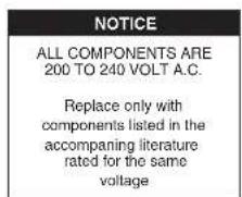
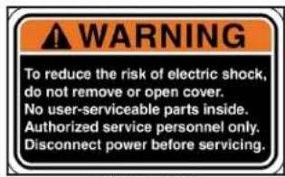
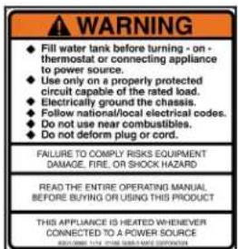
The notices on this dispenser should be kept in good condition. Replace unreadable or damaged labels.
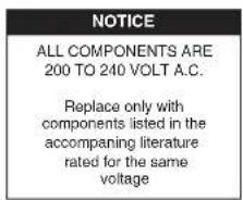
12537.0000
00657.0000
POUR IN WATER ONLY
00833.0000
As directed in the International Plumbing Code of the International Code Council and the Food Code Manual of the Food and Drug Administration (FDA), this equipment must be installed with adequate backflow prevention to comply with federal, state and local codes. For models installed outside the U.S.A., you must comply with the applicable Plumbing/Sanitation Code for your area.
00656.0001
12537.0000
29710.0017
37881.0000
29710.0018
00831.0000

00831.0000
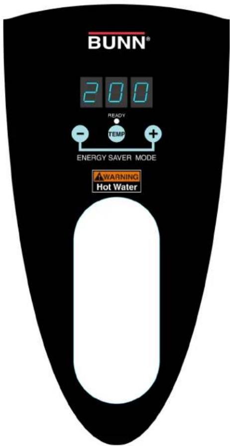
44025.0000 H5 Element (shown)
44025.0002 H3 Element P & H
44025.0004 H3 Element P/C

12593.0000

37881.0002
ELECTRICAL REQUIREMENTS
WARNING - The dispenser must be disconnected from the power source until specified in Initial Set-Up.
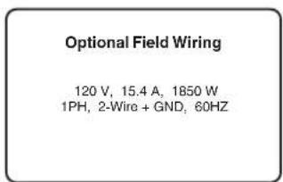
Refer to Data Plate on the Brewer, and local/national electrical codes to determine circuit requirements.
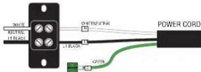
120 volt ac models
Note: This electrical service consists of 2 current carrying conductors (L1 and Neutral) and a separate conductor for earth ground.
Note: This electrical service consists of 2 current carrying conductors (L1 and Neutral) and a separate conductor for earth ground.
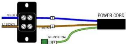
Note: This electrical service consists of 2 current carrying conductors (L1 and L2) and a separate conductor for earth ground.
Electrical Hook-Up
CAUTION – Improper electrical installation will damage electronic components.
- An electrician must provide electrical service as specified.
- Using a voltmeter, check the voltage and color coding of each conductor at the electrical source.
- Turn off master switch (if equipped).
- Remove the upper and lower rear panels.
- Install the proper electrical wiring to the terminal block.
- Connect the dispenser to the power source and verify the voltage at the terminal block before proceeding. Reinstall both rear panels.
- If plumbing is to be hooked-up later be sure the dispenser is disconnected from the power source. If Plumbing has been hooked-up, the dispenser is ready for Initial Set-Up.
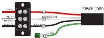
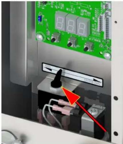
120/208 & 120/240V ac single phase models
Note: This electrical service consists of 3 current carrying conductors (Neutral, L1 and L2) and a separate conductor for earth ground.
DUAL VOLT TOGGLE SWITCH
PLUMBING REQUIREMENTS - ALL EXCEPT OHW
This dispenser must be connected to a COLD WATER system with operating pressure between 20 and 90 psi (0.138 and 0.620 mPa) from a 12'' or larger supply line. A shut-off valve should be installed in the line before the dispenser. Install a regulator in the line when pressure is greater than 90 psi (0.620 mPa) to reduce it to 50 psi (0.345 mPa). The water inlet fitting is 14'' flare (CE/UK inlet 3/4" BSP on H3EA Element only).
NOTE - Bunn-O-Matic recommends 14 " tubing for installations of less than 25 feet and 38 " for more than 25 feet from the 12 " water supply line. At least 18 inches of an FDA approved flexible beverage tubing, such as reinforced braided polyethylene or silicone, before the dispenser will facilitate movement to clean the countertop. Bunn-O-Matic does not recommend the use of a saddle valve to install the dispenser. The size and shape of the hole made in the supply line by this type of device may restrict water flow.
As directed in the International Plumbing Code of the International Code Council and the Food Code Manual of the Food and Drug Administration (FDA), this equipment must be installed with adequate backflow prevention to comply with federal, state and local codes. For models installed outside the U.S.A., you must comply with the applicable Plumbing /Sanitation Code for your area.
Plumbing Hook-Up
-
Remove the shipping cap from the fitting on the rear of the dispenser, and attach the flare elbow fitting (supplied separately with the dispenser) to the fitting (CE/UK inlet 3/4" BSP on H3EA Element only).
-
Flush the water line and securely attach it to the flare fitting.
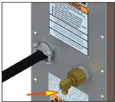
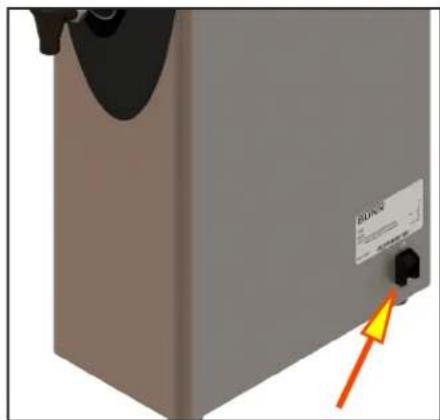
Plumbing Hook-Up Master ON/OFF switch
INITIAL SET-UP - H5E, H5X, H5-PC, H10X, H3/5 Element
CAUTION - The dispenser must be disconnected from the power source throughout the initial set-up, except when specified in the instructions.
- Connect dispenser to the power source and turn on water supply.
- Place Master ON/OFF switch in the ON position (if equipped). NOTE: (Digital models with display) When power is applied to the dispenser, the display will show the software version for 5 seconds, and then it will show the temperature.
- Water will automatically flow into the tank to the proper level and shut-off. When filled, the water heater will turn on automatically.
- The tank will heat to the (set) temperature.
- Refer to Programming to set the Tank Temperature and the Ready Temperature.
NOTE: On H3 Element only, a small amount of expansion water on back of drip tray is normal during initial and/or back to back heating cycles.
INITIAL SET-UP - H5M
CAUTION - The dispenser must be disconnected from the power source throughout the initial set-up, except when specified in the instructions.
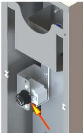
- Remove the upper rear panel and rotate the control thermostat knob fully counterclockwise to the "OFF" position and replace the panel.
- Connect the dispenser to the power source and turn-on the water supply.
- Water will automatically flow into the tank to the proper level and shut-off. This will take approximately 10 minutes.
- Disconnect the dispenser from the power source, remove the upper rear panel and place the control thermostat knob fully clockwise to the "ON" position, and replace the panel.
- Connect the dispenser to the power source and wait approximately twenty minutes for the water in the tank to heat.
- On models with ready indicator, the indicator will light up when the proper water temperature is achieved.
INITIAL SET-UP - HW2
CAUTION - The dispenser must be disconnected from the power source throughout the initial set-up, except when specified in the instructions.
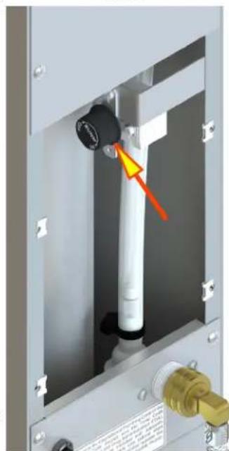
- Remove the center rear panel and rotate the control thermostat knob fully counterclockwise to the "OFF" position and replace the panel.
- Plug-in the dispenser.
- Water will automatically flow into the tank to the proper level and shut-off.
- Unplug the dispenser, remove the center rear panel and rotate the control thermostat knob fully clockwise to the "ON" position, and replace the panel.
- Plug-in the dispenser and wait approximately twenty minutes for the water in the tank to heat. The dispenser is ready for use.
INITIAL SET-UP - OHW
CAUTION - The dispenser must be unplugged throughout the initial set-up, except when specified in the instructions.
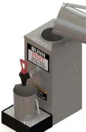
- Place an empty vessel under the faucet, lift the pour-in lid, and pour a full pitcher (64 oz) of tap water into the top of the dispenser. Hold open the faucet handle to allow air to escape from the tank while it is filling.
- Pour another full pitcher into the top. Close the faucet when water starts flowing from the faucet.
- Fill the top basin with additional water until it is approximately one inch from the top lid.
- Plug-in the dispenser and wait approximately 15 minutes for the water to heat to the proper temperature.
- The dispenser is now ready for use. (refer to the section on normal use.)
NORMAL USE
CAUTION - Water dispensed from this faucet is extremely hot . (Above 200° F.)
- Hold open the faucet whenever a cup of hot water is desired.
- Pour another full pitcher into the top whenever water is no longer available at the faucet. No wait is needed, the faucet is ready to dispense another cup of hot water.
NOTE - Due to the tank capacity and heater size, this product should be used only for dispensing a few cups of hot water at a time. (Larger capacity Bunn-O-Matic hot water dispensers are available.)
natural_image
3D mechanical assembly diagram showing a sliding contact mechanism with a highlighted component (no text or symbols)H5M
natural_image
Mechanical assembly diagram showing a cylindrical component with a red arrow pointing to a pin, mounted on a metal frame (no text or symbols visible)HW2
natural_image
3D rendering of a BUNN HOT water system with a cup and lid, no visible text or symbols on the device itself.OHW
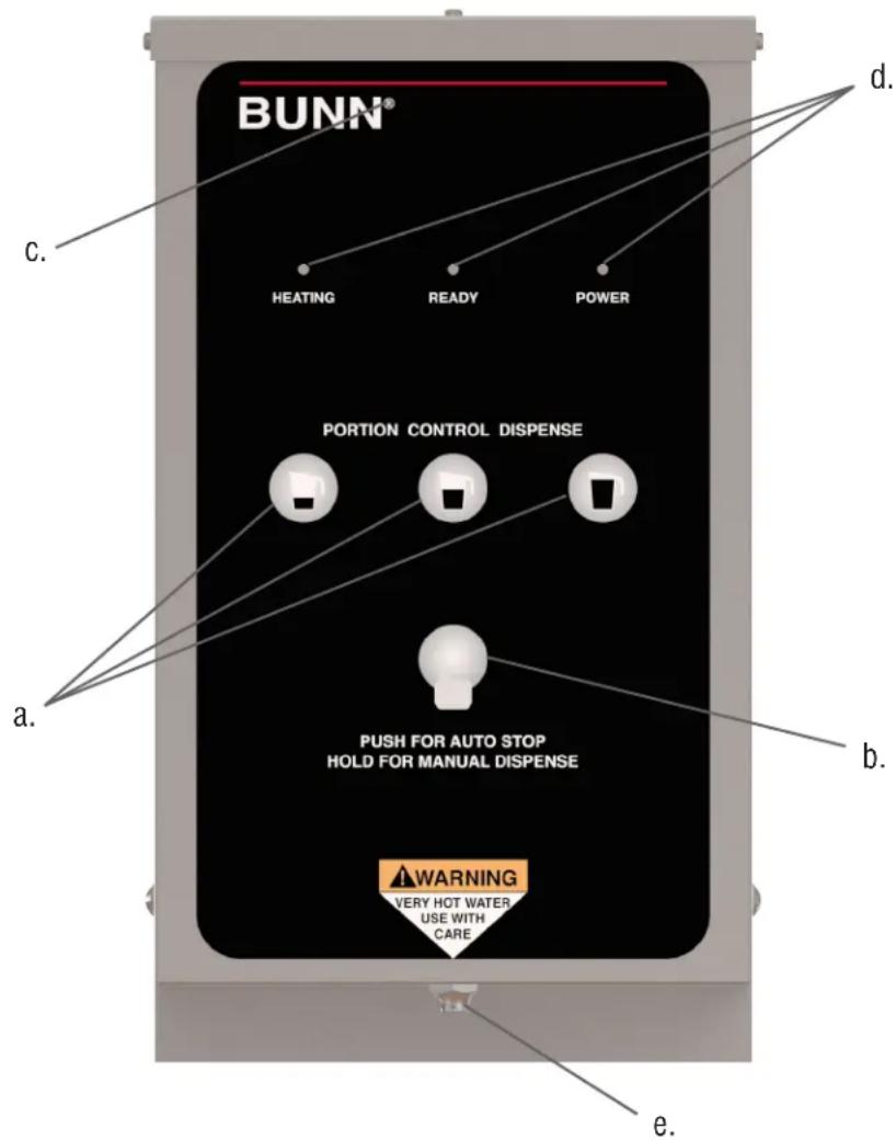
Press and release the button corresponding to the Small, Medium, or Large volume, to select the desired amount of water to be dispensed. Pressing a different button after a cycle has been initiated does not change the volume in progress.
(b) AUTO STOP/MANUAL DISPENSE BUTTON
Press and release button to stop a dispense cycle. Press and hold button to dispense manually.
(c) HIDDEN PROGRAMMING BUTTON
(d) LED INDICATORS
(e) DISPENSE NOZZLE
ADJUSTING DISPENSE VOLUMES
NOTE: The dispenser should be at operating temperature before setting dispense volumes.
- Press and hold the hidden programming button (c) located under the ® next to the BUNN logo on the front of the dispenser until the 3 LED's begin flashing from the left to the right. Release the button.
- Place an empty graduated container under the dispense nozzle (e).
- Press and release the batch size to be set (a). The LED's will stop flashing, and the LED over the button just pressed will come on steady. Water will begin to dispense into the container.
- When the desired amount of water is dispensed, press and release the same button (a). The water will stop dispensing and the batch size is now set.
- The LED's will begin flashing from left to right again. Repeat steps 2 thru 4 to set up the other batch sizes.
- To exit the programming set up at any time, press and release the hidden button once (c). The dispenser is now ready for use.
PROGRAMMING - H5-E, H5-PC, H5X, H10X
When power is applied to the dispenser, the display located on the bottom of the main circuit board will show the software version for 5 seconds, and then it will show the model number (see chart below) it will then go to (-). While the tank is filling, the display will read (FIL). When the tank is full the display will show the model number and then go to (-).
MODEL DISPLAYS (P1)
(H5H) 5 Gallon High Voltage Unit (200-240V)
(H5L) 5 Gallon Low Voltage Unit (100-120V)
(HPC) 5 Gallon Portion Control Unit (all)
(H10) 10X (all)
Switch must be in "SET" position for access into programming modes.
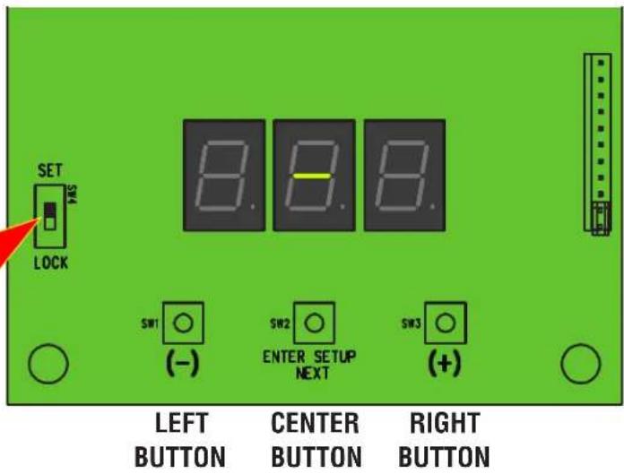
LEVEL 1 PROGRAMMING
- Before programming any settings into the Control Board, confirm the correct model number is entered.
- Do this by pressing and holding down on the center button until P1 appears on the display. Release the center button. The display will now show the model number (ex: H5H). Now scroll with the (+/-) buttons through the models listed above until the display matches the model you are working with.
- Press and release the center button once more. The display will show P2. Display will now show the tank temperature (ex: 200). Press the (+) button to increase the temperature set point, or the (-) button to decrease the set point.
NOTE: If the unit is a H5X or H10X, set the Tank Temperature to 212°F.
- After the Tank Temperature is entered, press and release the center button once more. The display will read P3, then show the ready temperature set point. Factory default is 195^ F for most dispensers, and 85^ F for some.
- Press the (+) button to increase the set point, or the (-) button to decrease the set point.
- To exit Level 1 Program press and release the center button once more. The display will show Software version, then model number, then (-).
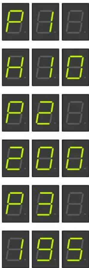
Continued
PROGRAMMING - H5-E, H5-PC, H5X, H10X Continued
LEVEL 2 PROGRAMMING
H1 - DISPENSE TEMPERATURE LOCKOUT - PORTION CONTROL ONLY (WILL NOT DISPLAY ON OTHER MODELS)
- To enter Level 2 Programming, press and hold the center button until H1 appears on the display (approximately 6 seconds) then release button. The display will either read noL (LOCKOUT DISABLED) or Loc (LOCKOUT ENABLED). When (ENABLED), unit will not dispense if the Tank Temperature is below the (READY) temperature setting.
- Use the (+) or (-) buttons to alternate between Loc and noL.
- Press and release the center button once more to advance to H2.
Or to exit Level 2, press and release the center button 3 times. Display will show, software version, then model number, then (-).
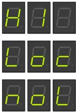
H2 - F° OR C° SELECTION
NOTE: Skip step 1 if going from H1 to H2.
- To enter Level 2 Programming, press and hold the center button until H2 appears on the display (approximately 6 seconds). Release the center button, The display will show either FAH (Degrees in Fahrenheit) or CEn (Degrees in Centigrade).
- Press and release the (+) or (-) buttons to alternate between FAH and CEn.
- After setting FAH or CEn, to exit Level 2 Programming, press and release the center button twice. Display will show, software version, then model number, then (-).
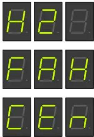
H3 - RESTORING FACTORY DEFAULTS
- To restore Factory Defaults (This clears all settings that were previously entered), press and release the center button until H2 appears on the display (approximately 6 seconds). Release the Center Button, then press and release the Center Button once more. The display will read H3, then show (- - - ).
- Press and hold both (+) and (-) buttons to initiate the resetting of the factory default settings. The display (---) will flash on and off during this time (about 5 to 7 seconds).
- When the factory default numbers are loaded in, the display will stop flashing, then read don (DONE). You can now release the two buttons.
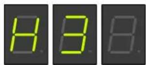
NOTE: If you release the two buttons at any time before the display reads don, the Factory Default numbers will not be entered. The old numbers will remain in the memory.
- To exit Level 2 Programming press and release the center button once more. The display will show the Software version, then model number, then (-).
PROGRAMMING - H5-ELEMENT
Adjusting temperature:
The switch must be in the "SET" position in order to access the program modes.
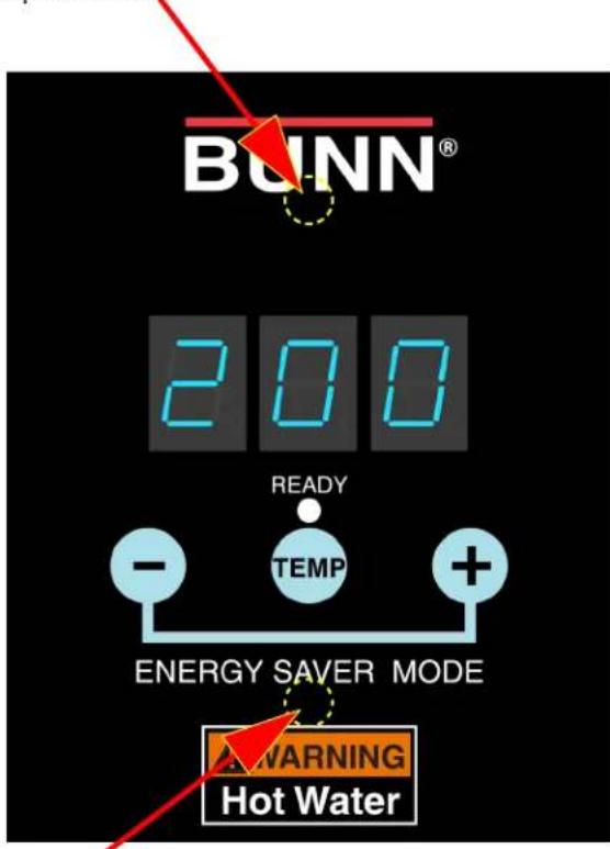
- Press and hold "TEMP" button until display flashes.
- While display is flashing, press and release the (+) to increase or (-) to decrease temperature.
NOTE: (Starting with software version 0.07)
If unit is "E" model, temp will stop at 211°F (99°C). If unit is "X" model, temp display will jump from 211°F (96°C) to 212°F (100°C).
Refer to chart on page 3 and adjust temperature requirements according to altitude.
Program lockout switch:
The switch must be in the "SET" position in order to access the program modes.
- Disconnect the dispenser from the power source.
- Remove the 4-40 screws and the top cover.
- Use a small screwdriver to move switch to set position.
- Install top cover, connect dispenser to power source.
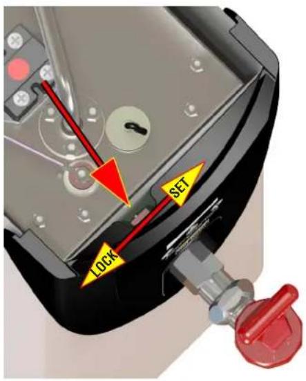
Manual Energy Saver Mode:
The energy save mode will allow the tank temperature to drop down to 140^ F ( 60^ C).
- Simultaneously press and release the (+) and (-) to "manually" activate energy save mode.
- The display will alternately flash between 140 and the current temperature to indicate it is in the energy save mode.
- Repeat procedure to exit energy save mode.
Step forward
Step backward
Programming the dispenser:
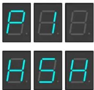
- Press and hold upper hidden button (bottom center of "BUNN" logo) until "P1" is displayed.
Continued
PROGRAMMING - H5-ELEMENT Continued
- The display will now show the model number.
(H5H) 5 Gallon High Voltage Unit (200-240V)
(H5L) _ 5 Gallon Low Voltage Unit (100-120V)
Now scroll with the (+/-) buttons through the models listed above until the display matches the model you are working with.
- Press and release the upper hidden button once more. The display will show P2.
Display will now show the "SET" temperature (ex: 200). Press the (+) button to increase the temperature set point, or the (-) button to decrease the set point.
Range: 60°F (15°C) to 211°F (99°C) NOTE: Temp will go to 212°F (100°C) on H5X.
- After the Tank Temperature is entered, press and release the upper hidden button once more. The display will read P3, then show the ready temperature set point.
Range: 2° to 20° below the "SET" temperature.
-
Press the (+) button to increase, or the (-) button to decrease the set point.
-
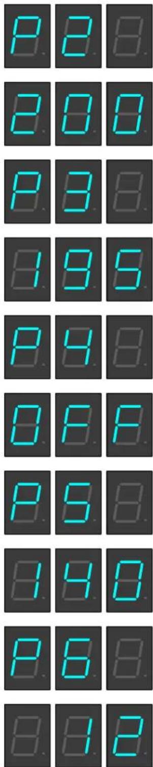
Press and release the upper hidden button once more. The display will read P4.
This screen will allow you to turn the "Auto" energy save mode ON/OFF.
NOTE: Turning off this function will disable "P5" and "P6".
- Press and release the upper hidden button once more. The display will read P5.
This will toggle the energy save mode from 140°F (60°C) or tank heater "OFF".
- Press and release the upper hidden button once more. The display will read P6.
This is the time delay from the last refill to the activation of energy save mode.
Range: 4 hours to 24 hours.
PROGRAMMING - H5-ELEMENT Continued
LEVEL 2 PROGRAMMING
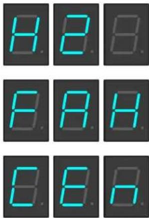
H2 - F° OR C° SELECTION
- To enter Level 2 Programming, press and hold the upper hidden button until H2 appears on the display. Release the upper hidden button. The display will show either FAH (Degrees in Fahrenheit) or CEn (Degrees in Centigrade).
- Press and release the (+) or (-) buttons to alternate between FAH and CEn.
- After setting FAH or CEn, to exit Level 2 Programming, press and release the upper hidden button twice. Display will show, software version, then main screen.
H3 - RESTORING FACTORY DEFAULTS
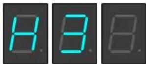
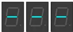
- To restore Factory Defaults (This clears all settings that were previously entered), press and release the upper hidden button until H2 appears on the display (approximately 6 seconds). Release the upper hidden Button, then press and release the upper hidden Button once more. The display will read H3, then show (- - - ).
- Press and hold both (+) and (-) buttons to initiate the resetting of the factory default settings. The display (---) will flash on and off during this time.
- When the factory default numbers are loaded in, the display will stop flashing, then read don (DONE). You can now release the two buttons.
natural_image
Three identical grayscale images showing a single blue horizontal line on a dark background, no text or symbols present.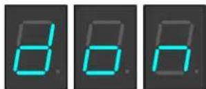
NOTE: If you release the two buttons at any time before the display reads don, the Factory Default numbers will not be entered. The old numbers will remain in the memory.
PROGRAMMING - H3E ELEMENT
Program lockout switch:
The switch must be in the "SET" position in order to access the program modes.
-
Disconnect the dispenser from the power source.
-
Remove the 4-40 screws and the top cover.
-
Looking from back to front, use a small screwdriver (or similar item) through slot in front housing to move switch to set position.
-
Install top cover, connect dispenser to power source.
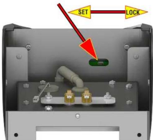
Programming button
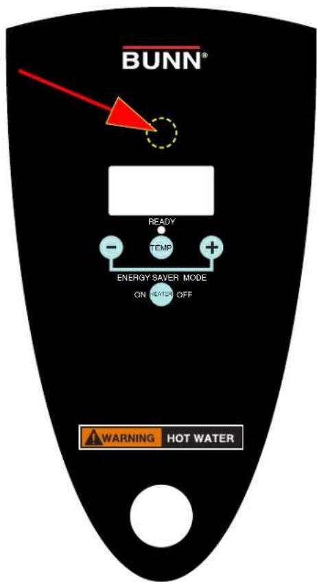
PROGRAMMING - H3E ELEMENT Continued
For software versions prior to 5.11
- Press and release the hidden button. The display will show P1. Display will now show the "SET" temperature. Press the (+) button to increase the temperature set point, or the (-) button to decrease the set point.
Range: 15°C (60°F) to 96°C (205°F). Default: 93°C.
- After the Tank Temperature is entered, press and release the hidden button once more. The display will read P2, then show the ready temperature set point.
Range: 2°C to 10°C below the "SET" temperature. Default: 90°C.
-
Press the (+) button to increase, or the (-) button to decrease the set point.
-
Press and release the hidden button once more. The display will read P3. This screen will allow you to turn the "Auto" energy save mode ON/OFF. Default: OFF.
NOTE: Turning off this function will disable "P4" and "P5".
-
Press and release the hidden button once more. The display will read P4. This will toggle the energy save mode from 60°C (140°F) or tank heater "OFF".
-
Press and release the upper hidden button once more. The display will read P5. This is the time delay from the last refill to the activation of energy save mode. Range: 4 hours to 24 hours.

PROGRAMMING - H3E ELEMENT Continued
LEVEL 2 PROGRAMMING
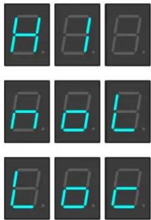
H1 - DISPENSE LOCKOUT
- To enter Level 2 Programming, press and hold the hidden button until H1 appears on the display. Release the hidden button. The display will show "noL" (no lockout) or Loc (dispense lockout).
- Press and release the (+) or (-) buttons to alternate between noL and Loc.
H2 - C° OR F° SELECTION
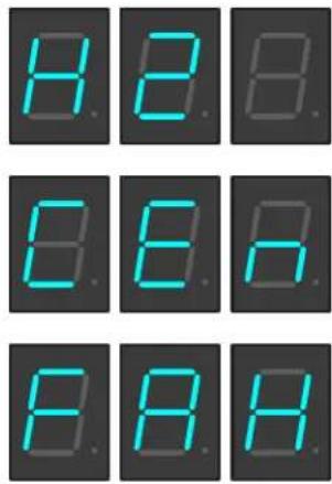
- To enter Level 2 Programming, press and hold the hidden button until H1 appears on the display. Press and release the hidden button. The display will show CEn (Degrees in Centigrade) or FAH (Degrees in Fahrenheit)
- Press and release the (+) or (-) buttons to alternate between FAH and CEn.
H3 - RESTORING FACTORY DEFAULTS
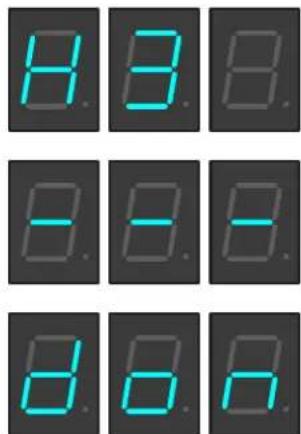
- To restore Factory Defaults (This clears all settings that were previously entered), press and release the hidden button until H1 appears on the display. Press and release the hidden button, then press and release the hidden button once more. The display will read H3, then show (- - -).
- Press and hold both (+) and (-) buttons to initiate the resetting of the factory default settings. The display (---) will flash on and off during this time.
- When the factory default numbers are loaded in, the display will stop flashing, then read don (DONE). You can now release the two buttons.
NOTE: If you release the two buttons at any time before the display reads don, the Factory Default numbers will not be entered. The old numbers will remain in the memory.
PROGRAMMING - H3E/X ELEMENT Continued
For software versions 5.11 and above
P1: Model selection. H5H, H5L, H3 toggle through model numbers with +/-

P2: Press and release the hidden button. The display will show P2. Display will now show the "SET" temperature. Press the (+) button to increase the temperature set point, or the (-) button to decrease the set point.
Range: 15°C (60°F) to 96°C (205°F). Default: 93°C (200°F)
P3: After the Tank Temperature is entered, press and release the hidden button once more. The display will read P3, then show the ready temperature set point.
Range: 2°C (2°F) to 10°C (20°F) below the "SET" temperature. Default: 5°F. Press the (+) button to increase, or the (-) button to decrease the set point.
P4: Press and release the hidden button once more. The display will read P4. This screen will allow you to turn the "Auto" energy save mode ON/OFF. Default: OFF.
NOTE: Turning off this function will disable "P5" - "P6".
P5: Press and release the hidden button once more. The display will read P5. This will toggle the energy save mode from 60°C (140°F) or tank heater "OFF".
PROGRAMMING - H3E ELEMENT Continued
P6: Press and release the upper hidden button once more. The display will read P6. This is the time delay from the last refill to the activation of energy save mode. Range: 4 hours to 24 hours.
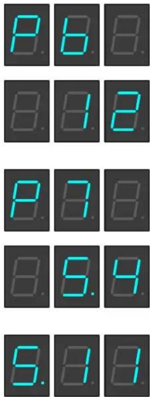
P7: Press and release the upper hidden button once more. The display will read P7. This sets the dispense time for "Portion Control". Default is "0" (Push & Hold).
During exit of program mode, software version will be displayed.
NOTE: Refer to page 17 for H1 - H3 modes.
DRAINING THE DISPENSER
- OHW
CAUTION - The dispenser must be disconnected from the power source throughout these steps.
- Disconnect the dispenser from the power source and allow dispenser to cool.
- Tilt dispenser forward over sink.
- Open faucet.
- Continue tilting dispenser forward over sink until water stops flowing.
NOTE - The dispenser must be full using the INITIAL SET-UP steps before reconnecting to the power source.
- ALL 2, 3 & 5 GALLON MODELS
- Disconnect the dispenser from the power source and allow dispenser to cool.
- Remove upper rear access cover(s).
- Close the white shutoff clamp on the long hose between tank and inlet solenoid.
- Disconnect the hose clamp and hose from inlet solenoid or check valve.
- Place the end of the drain hose in a container that has a minimum capacity of 2.0 gallons (7.5 L) HW2, 5Gal/18.9L for H5E,M,X, & Element.
- Release the white clamp to drain water from the tank.
- When tank is empty, replace the hose onto solenoid (or flow control) and tighten the black clamp.
- Replace the access cover.
NOTE: Do not tighten white clamp!
- 10 GALLON MODELS
- Disconnect the dispenser from the power source and allow dispenser to cool.
- Remove left side access cover.
- Close the white shutoff clamp on the long hose that is teed between tank and inlet solenoid.
- Disconnect the hose clamp and plug from loose end of long hose.
- Place the end of the drain hose in a container that has a minimum capacity of 10Gal/37.8L.
- Release the white clamp to drain water from the tank.
- When tank is empty, replace the clamp and plug and tighten the black clamp.
- Replace the access cover.
Alternate method:
- ALL 2, 5 & 10 GALLON MODELS
CAUTION - The dispenser must be disconnected from the power source throughout these steps.
- Disconnect the dispenser from the power source.
- Shut-off and disconnect the incoming water supply and allow dispenser to cool.
- Remove the 4-40 screws and the top cover.
- Gently remove one of the grommets from the tank lid.
- Insert a tube to the bottom of the tank and syphon ALL of the water out.
CLEANING
The use of a damp cloth rinsed in any mild, non-abrasive, liquid detergent is recommended for cleaning all surfaces on Bunn-O-Matic equipment.
WALL MOUNTED INSTALLATION - 5 GALLON MODELS ONLY
If the dispenser is wall mounted, the bottom of the dispenser should be at the same height as a counter or table top. Use B.O.M. part #12542.0000 for side mounted Wall Bracket Kit or # 13125.0001 for front mounted Wall Bracket Kit.
SUPPORT FOR LARGE RECEPTACLES
CAUTION: If the dispenser is to be used with larger receptacles such as pitchers or pots, those receptacles must be adequately supported during dispensing of hot water to avoid spillage of very hot water. This support may be provided by a table or counter top, or use B.O.M. part #12599.0000 Shelf Kit.
- BUNN-O-MATIC COMMERCIAL PRODUCT WARRANTY
- CONTENTS
- INTRODUCTION
- CE REQUIREMENTS
- NORTH AMERICAN REQUIREMENTS
- USER NOTICES
- POUR IN WATER ONLY
- ELECTRICAL REQUIREMENTS
- Refer to Data Plate on the Brewer, and local/national electrical codes to determine circuit requirements.
- Electrical Hook-Up
- PLUMBING REQUIREMENTS - ALL EXCEPT OHW
- Plumbing Hook-Up
- INITIAL SET-UP - H5E, H5X, H5-PC, H10X, H3/5 Element
- INITIAL SET-UP - H5M
- INITIAL SET-UP - HW2
- INITIAL SET-UP - OHW
- NORMAL USE
- AUTO STOP/MANUAL DISPENSE BUTTON
- HIDDEN PROGRAMMING BUTTON
- LED INDICATORS
- DISPENSE NOZZLE
- ADJUSTING DISPENSE VOLUMES
- PROGRAMMING - H5-E, H5-PC, H5X, H10X
- MODEL DISPLAYS (P1)
- LEVEL 1 PROGRAMMING
- NOTE: If the unit is a H5X or H10X, set the Tank Temperature to 212°F.
- Continued
- PROGRAMMING - H5-E, H5-PC, H5X, H10X Continued
- LEVEL 2 PROGRAMMING
- H1 - DISPENSE TEMPERATURE LOCKOUT - PORTION CONTROL ONLY (WILL NOT DISPLAY ON OTHER MODELS)
- H2 - F° OR C° SELECTION
- H3 - RESTORING FACTORY DEFAULTS
- PROGRAMMING - H5-ELEMENT
- Adjusting temperature:
- Program lockout switch:
- Manual Energy Saver Mode:
- Programming the dispenser:
- PROGRAMMING - H5-ELEMENT Continued
- PROGRAMMING - H3E ELEMENT
- PROGRAMMING - H3E ELEMENT Continued
- For software versions prior to 5.11
- H1 - DISPENSE LOCKOUT
- H2 - C° OR F° SELECTION
- PROGRAMMING - H3E/X ELEMENT Continued
- For software versions 5.11 and above
- DRAINING THE DISPENSER
- - OHW
- - ALL 2, 3 & 5 GALLON MODELS
- NOTE: Do not tighten white clamp!
- - 10 GALLON MODELS
- Alternate method:
- - ALL 2, 5 & 10 GALLON MODELS
- CLEANING
- WALL MOUNTED INSTALLATION - 5 GALLON MODELS ONLY
- SUPPORT FOR LARGE RECEPTACLES
Brand : Bunn
Model : H3X Element
Category : Water dispenser