
ULTRA-2A R452 - Water dispenser Bunn - Free user manual and instructions
Find the device manual for free ULTRA-2A R452 Bunn in PDF.


| Product Type | Water Dispenser |
| Brand | Bunn |
| Model | ULTRA-2A R452 |
| Dimensions (H x W x D) | 30 x 16 x 20 inches |
| Weight | 40 lbs |
| Power Supply | 115 V, 60 Hz, 10 A |
| Water Connection | Direct plumbed (1/4" line) |
| Dispensing Options | Hot and Cold Water |
| Hot Water Temperature | Approximately 200°F (93°C) |
| Cold Water Temperature | Approximately 50°F (10°C) |
| Capacity | 3 gallons hot, 6 gallons cold (reservoir) |
| Flow Rate | 1.5 gallons per minute (cold); 0.5 gpm (hot) |
| Safety Features | UL Listed, automatic shutoff, anti-scald protection |
| Installation | Countertop or wall-mount (bracket included) |
| Maintenance | Descale every 6 months; replace internal filter annually |
| Cleaning | Exterior wipe with damp cloth; internal flush with vinegar solution |
| Spare Parts Availability | Available from Bunn authorized dealers |
| Warranty | 1 year parts and labor |
| Certifications | NSF/ANSI 372 (lead-free), UL 399 |
| Material | Stainless steel exterior, BPA-free plastic interior |
Frequently Asked Questions - ULTRA-2A R452 Bunn
User questions about ULTRA-2A R452 Bunn
0 question about this device. Answer the ones you know or ask your own.
Ask a new question about this device
Download the instructions for your Water dispenser in PDF format for free! Find your manual ULTRA-2A R452 - Bunn and take your electronic device back in hand. On this page are published all the documents necessary for the use of your device. ULTRA-2A R452 by Bunn.
USER MANUAL ULTRA-2A R452 Bunn
natural_image
Two modern water filtration machines with white and black branding, no visible text or symbols on the devices themselves.INSTALLATION & OPERATING GUIDE
For Technical Service, contact Bunn-O-Matic Corporation at 1-800-286-6070.
Bunn-O-Matic Corporation
Post Office Box 3227, Springfield, Illinois 62708-3227
Phone (217) 529-6601 | Fax (217) 529-6644
BUNN-O-MATIC COMMERCIAL PRODUCT WARRANTY
Bunn-O-Matic Corp. ("BUNN") warrants equipment manufactured by it as follows:
1) Airpots, thermal carafes, decanters, GPR servers, iced tea/coffee dispensers, MCR/MCP/MCA single cup brewers, thermal servers and ThermoFresh® servers (mechanical and digital) 1 year parts and 1 year labor.
2) All other equipment - 2 years parts and 1 year labor plus added warranties as specified below:
a) Electronic circuit and/or control boards - parts and labor for 3 years.
b) Compressors on refrigeration equipment - 5 years parts and 1 year labor.
c) Grinding burrs on coffee grinding equipment for 4 years or 40,000 pounds of coffee, whichever comes first.
These warranty periods run from the date of installation BUNN warrants that the equipment manufactured by it will be commercially free of defects in material and workmanship existing at the time of manufacture and appearing within the applicable warranty period. This warranty does not apply to any equipment, component or part that was not manufactured by BUNN or that, in BUNN's judgment, has been affected by misuse, neglect, alteration, improper installation or operation, improper maintenance or repair, non periodic cleaning and descaling, equipment failures related to poor water quality, damage or casualty. In addition, the warranty does not apply to replacement of items subject to normal use including but not limited to user replaceable parts such as seals and gaskets. This warranty is conditioned on the Buyer 1) giving BUNN prompt notice of any claim to be made under this warranty by telephone at (217) 529-6601 or by writing to Post Office Box 3227, Springfield, Illinois 62708-3227; 2) if requested by BUNN, shipping the defective equipment prepaid to an authorized BUNN service location; and 3) receiving prior authorization from BUNN that the defective equipment is under warranty.
THE FOREGOING WARRANTY IS EXCLUSIVE AND IS IN LIEU OF ANY OTHER WARRANTY, WRITTEN OR ORAL, EXPRESS OR IMPLIED, INCLUDING, BUT NOT LIMITED TO, ANY IMPLIED WARRANTY OF EITHER MERCHANTABILITY OR FITNESS FOR A PARTICULAR PURPOSE. The agents, dealers or employees of BUNN are not authorized to make modifications to this warranty or to make additional warranties that are binding on BUNN. Accordingly, statements by such individuals, whether oral or written, do not constitute warranties and should not be relied upon.
If BUNN determines in its sole discretion that the equipment does not conform to the warranty, BUNN, at its exclusive option while the equipment is under warranty, shall either 1) provide at no charge replacement parts and/or labor (during the applicable parts and labor warranty periods specified above) to repair the defective components, provided that this repair is done by a BUNN Authorized Service Representative; or 2) shall replace the equipment or refund the purchase price for the equipment.
THE BUYER'S REMEDY AGAINST BUNN FOR THE BREACH OF ANY OBLIGATION ARISING OUT OF THE SALE OF THIS EQUIPMENT, WHETHER DERIVED FROM WARRANTY OR OTHERWISE, SHALL BE LIMITED, AT BUNN'S SOLE OPTION AS SPECIFIED HEREIN, TO REPAIR, REPLACEMENT OR REFUND.
In no event shall BUNN be liable for any other damage or loss, including, but not limited to, lost profits, lost sales, loss of use of equipment, claims of Buyer's customers, cost of capital, cost of down time, cost of substitute equipment, facilities or services, or any other special, incidental or consequential damages.
392, A Partner You Can Count On, Air Infusion, AutoPOD, AXIOM, BrewLOGIC, BrewMETER, Brew Better Not Bitter, BrewWISE, BrewWIZARD, BUNN Espress, BUNN Family Gourmet, BUNN Gourmet, BUNN Pour-O-Matic, BUNN, BUNN with the stylized red line, BUNNlink, Bunn-OMatic, Bunn-O-Matic, BUNNserve, BUNNSERVE with the stylized wrench design, Cool Froth, DBC, Dr. Brew stylized Dr. design, Dual, Easy Pour, EasyClear, EasyGard, FlavorGard, Gourmet Ice, Gourmet Juice, High Intensity, iMIX, Infusion Series, Intellisteam, My Café, Phase Brew, PowerLogic, Quality Beverage Equipment Worldwide, Respect Earth, Respect Earth with the stylized leaf and coffee cherry design, Safety-Fresh, savemycoffee.com, Scale-Pro, Silver Series, Single, Smart Funnel, Smart Hopper, SmartWAVE, Soft Heat, SplashGard, The Mark of Quality in Beverage Equipment Worldwide, ThermoFresh, Titan, trifecta, TRIFECTA (sylized logo), Velocity Brew, Air Brew, Beverage Bar Creator, Beverage Profit Calculator, Brew better, not bitter., Build-A-Drink, BUNNSource, Coffee At Its Best, Cyclonic Heating System, Daypart, Digital Brewer Control, Element, Milk Texturing Fusion, Nothing Brews Like a BUNN, Picture Prompted Cleaning, Pouring Profits, Signature Series, Sure Tamp, Tea At Its Best, The Horizontal Red Line, Ultra are either trademarks or registered trademarks of Bunn-O-Matic Corporation. The commercial trifecta® brewer housing configuration is a trademark of Bunn-O-Matic Corporation.
INTRODUCTION
This equipment dispenses granita-type and cold liquid drinks on demand from separate hoppers. Operating controls are accessible only through password protection.
CONTENTS
Warranty 2
Introduction.... 3
Site Preparation.... 3
North American and CE Requirements 4
User Notices 5
Electrical Requirements.... 5
Initial Setup 6 - 7
Handle Installation Instructions.... 8
Internal Brixing System Adjustment Instructions 8 - 9
Operating Controls.... 10
Using the Dispenser for Granita-Type Products.... 11
Using the Dispenser for Cold Liquid Products 11
Programming 12 - 15
Other Recommendations For Your Dispenser.... 16
Preventive Maintenance 17
Recommended Daily Cleaning 18
Assembly Following Cleaning.... 19
Autofill Installation Instructions 20
CF Autofill Installation Instructions.... 21
Autofill Cleaning Instructions 22 - 23
SITE PREPARATION
The dispenser is very heavy. Place it on a sturdy counter or shelf capable of supporting at least 180 lbs. It is for indoor use only.
The dispenser must have at least six inches of space behind it. This space is needed for airflow, air filter removal, and cleaning. A clearance of at approximately six inches is recommended between the dispenser sides and the wall or another appliance. The dispenser performs better if not placed near any heating appliance. Leave some space so the dispenser can be moved for cleaning.
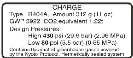
This equipment contains fluorinated greenhouse gases covered by the Kyoto Protocol. Hermetically sealed system. Type R404a, 312 g (11 oz), GWP 3922, CO2 equivalent 1.22t.
This equipment contains fluorinated greenhouse gases covered by the Kyoto Protocol. Hermetically sealed system. Type R452a, 312 g (11 oz), GWP 2140, CO2 equivalent 0.67t.
NORTH AMERICAN REQUIREMENTS
- This appliance must be installed in locations where it can be overseen by trained personnel.
- For proper operation, this appliance must be installed where the temperature is between 41°F to 90°F (5°C to 32°C).
- For proper operation, this appliance must be installed where humidity is 50%.
- Appliance shall not be tilted more than 10^ for safe operation.
- An electrician must provide electrical service as specified in conformance with all local and national codes.
- This appliance must not be cleaned by pressure washer.
- This appliance can be used by persons if they have been given supervision or instruction concerning use of the appliance in a safe way and if they understand the hazards involved.
- Keep the appliance and its cord out of reach of children.
- Appliances can be used by persons with reduced physical, sensory or mental capabilities or lack of experience and knowledge if they have been given supervision or instruction concerning use of the appliance in a safe way and understand the hazards involved.
- If the power cord is ever damaged, it must be replaced by the manufacturer or authorized
- ser vice personnel with a special cord available from the manufacturer or its authorized service personnel in order to avoid a hazard.
- Machine must not be immersed for cleaning.
- This appliance is intended for commercial use in applications such as:
- staff kitchen areas in shops, offices and other working environments
- by clients in hotel and motel lobbies and other similar types of environments
- Access to the service areas permitted by Authorized Service personnel only.
CE REQUIREMENTS
- This appliance must be installed in locations where it can be overseen by trained personnel.
- For proper operation, this appliance must be installed where the temperature is between 5°C to 32°C.
- For proper operation, this appliance must be installed where humidity is 50%.
- Appliance shall not be tilted more than 10^ for safe operation.
- An electrician must provide electrical service as specified in conformance with all local and national codes.
- This appliance must not be cleaned by water jet.
- This appliance is not intended for use by persons (including children) with reduced physical, sensory or mental capabilities, or lack of experience and knowledge, unless they have been given instructions concerning use of this appliance by a person responsible for its safety.
- Children should be supervised to ensure they do not play with the appliance.
- If the power cord is ever damaged, it must be replaced by the manufacturer or authorized service personnel with a special cord available from the manufacturer or its authorized service personnel in order to avoid a hazard.
- Machine must not be immersed for cleaning.
• Machine rated IX P1.
USER NOTICES
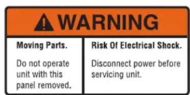
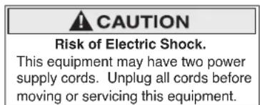
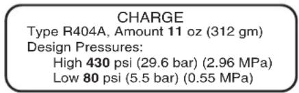
Carefully read and follow all notices on the equipment and in this manual. They were written for your protection. All notices are to be kept in good condition. Replace any unreadable or damaged labels.
27442.0000

00986.0000
29373.0002 (ULTRA-2)
29947.0000
INTENDED FOR USE AT A ROOM TEMPERATURE OF 27C (80F)
29979.0000
29373.0001 (ULTRA-2 PAF)
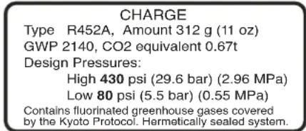
29373.0003 (ULTRA-2A)
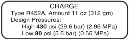
29373.0004 (ULTRA-2)
ELECTRICAL REQUIREMENTS
CAUTION – Improper electrical installation will damage components. An electrician must provide electrical service as specified below.
Model ULTRA-2: This dispenser has an attached cordset and requires a 2-wire, grounded, individual branch circuit rated 120 volts ac, 15 amp, single phase, 60 Hz. The mating connector must be a NEMA 5-15R. (Refer to the dataplate for exact electrical requirements.)
Model ULTRA-2A: This dispenser has an attached cordset and requires a 2-wire, grounded, individual branch circuit rated 220-240 volts ac, 10 amp, single phase, 50/60 Hz. (Refer to the dataplate for exact electrical requirements.)
Model ULTRA-2B: This dispenser has an attached cordset and requires a 2-wire, grounded, individual branch circuit rated 100 volts ac, 10 amp, single phase, 50 Hz. (Refer to the dataplate for exact electrical requirements.)
NOTE: Bunn-O-Matic does not recommend the use of any extension cord with these dispensers.
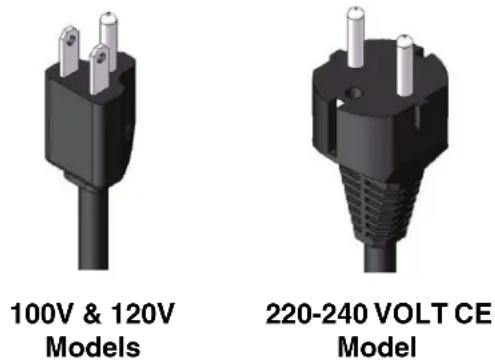
120 & 220-240 Volt AC Models
NOTE: This electrical service consists of 2 current carrying conductors (L1 and Neutral) and a separate conductor for chassis ground.
INITIAL SETUP
CAUTION – The dispenser is very heavy! Use care when lifting or moving it. Use at least two people to lift or move the dispenser.
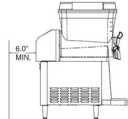
- Set the dispenser on a sturdy counter top. The dispenser requires a minimum of 6.0" air clearance at the rear of the dispenser. For optimum performance, do not let warm air from surrounding machines blow on the ULTRA dispenser.
NOTE: The dispenser should be level or slightly lower in front for proper operation.
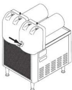
- Remove all shipping material, including the compressor support eyebolt, the cooling drum supports, the "Do Not Lift Here" signs from the cooling drums, and the "Rinse Before Using" signs from the hopper(s). For models without PAF (Powder Auto-Fill), proceed to step #9.
natural_image
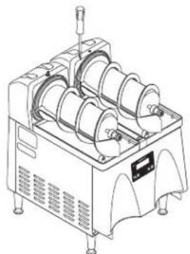
Line drawing of a mechanical device with rollers and a handle (no text or symbols)- Remove the rear plastic plug from the trim strip between the auger motor covers.
natural_image
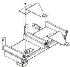
Technical line drawing of a mechanical device with multiple coiled components and mounting feet (no text or symbols)- Remove the rear most plastic plug from the trim strip between cooling drums and remove screw.
natural_image
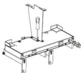
Technical line drawing of a mechanical assembly with mounting brackets and a vertical axis (no text or symbols)- Remove the RCA plug access cover.
natural_image
Technical line drawing of a mechanical assembly with mounting brackets and a vertical support (no text or symbols)- Install the platform mounting bracket using the screws provided in kit.
natural_image
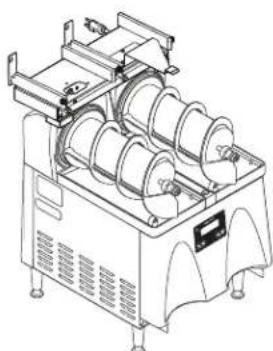
Technical line drawing of a mechanical device with multiple rollers and mounting brackets (no text or symbols)- Place the platform assembly on top of the auger motor covers and install screws.
natural_image
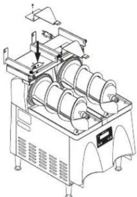
Technical line drawing of a mechanical device with multiple rollers and mounting brackets (no text or symbols)- Plug RCA cord into ULTRA base unit. Replace access cover and screws. Proceed with steps 9 thru 13.
INITIAL SETUP (continued)
natural_image
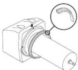
Technical line drawing of a mechanical component with a magnified inset showing a curved groove (no text or symbols)- Install each hopper seal over the flange at the rear of the cooling drums as shown.
natural_image
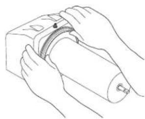
Line drawing of hands holding a cylindrical device with a curved handle (no text or symbols)- Press the seals firmly into place.
natural_image
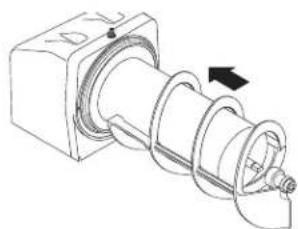
Technical line drawing of a mechanical component with a spiral shaft and housing (no text or symbols)- Align the auger shaft with the flat fin of the auger. Push the augers as far as they will go and rotate them so the flat fin is facing up.
natural_image
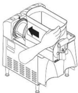
Line drawing of a mechanical device with hands operating it, no text or symbols present- Thoroughly rinse the hoppers and install them over the augers and cooling drums.
natural_image
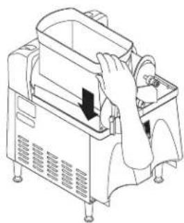
Line drawing of a hand operating a mechanical device with a handle and control panel (no text or symbols)- Slide the hopper(s) into place and push down until the hopper lock plunger snaps into place. For models without PAF, proceed to step 15.
natural_image
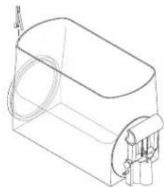
Line drawing of a rectangular device with a curved top and side connectors (no text or symbols)- For models with PAF, install level probes into slots at top rear of PAF hoppers.

natural_image
Technical line drawing of a dual-tiered industrial machine with control panel and mounting base (no text or symbols)- Install PAF unit onto platform and plug power cord into rear of platform. Plug platform power cord into proper outlet. (Refer to PAF manual for water connections)(Proceed to step 18)
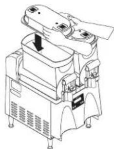
natural_image
Technical line drawing of a mechanical device with no visible text or symbols- Set the lid(s) on the hopper(s). Lift slightly and slide back or front for filling.
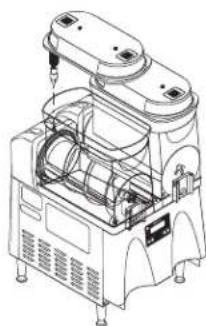
natural_image
Technical line drawing of a mechanical device with internal components and mounting feet (no text or symbols)- Plug in the hopper lid lamp cord(s).
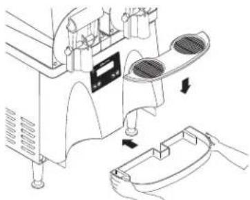
natural_image
Technical line drawing of a mechanical device with labeled components and directional arrows indicating motion (no text or symbols present)- Assemble the drip tray.
HANDLE INSTALLATION INSTRUCTIONS
- Start the right side of the handle over the pivot pin. 2. While slightly twisting the handle, spread the left side over the pivot pin to snap into place.
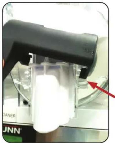
natural_image
Close-up of a black and white industrial machine component with a red arrow pointing to a white cylindrical part (no visible text or symbols)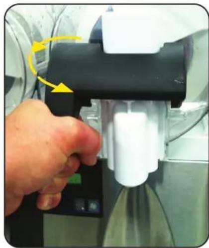
natural_image
Close-up of a hand operating a mechanical device with a yellow arrow indicating rotation (no text or symbols visible)- To remove the handle, twist in the same direction to free the handle from the left pivot pin, then slide off of the right pin.
INTERNAL BRIXING SYSTEM BRIX ADJUSTMENT INSTRUCTIONS
natural_image
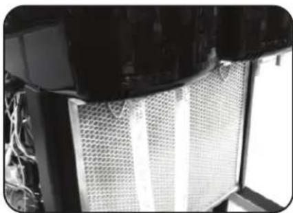
Close-up of a metallic mesh structure with visible internal components, no text or symbols present.- Connect syrup supply lines from BIB system. Connect water lines from source. NOTE: Connection points for these are marked on the rear of the motor cover.
natural_image
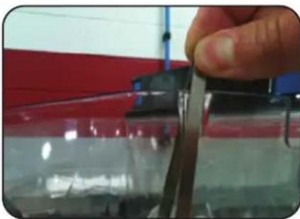
Close-up of a hand holding a small metallic object against a red and black background (no visible text or symbols)- Install hoppers onto machine and slide probes onto hoppers into slots provided.
natural_image
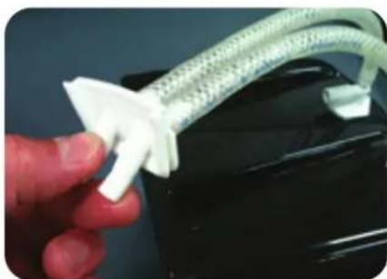
Close-up of a hand holding a white plastic hose with a white connector, against a dark background (no text or symbols visible)- Route the tubes from the motor cover together and connect to hopper fitting.
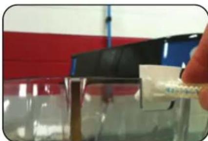
natural_image
Close-up of a hand holding a small white object over a glass container, with a red and blue background (no visible text or symbols)- Slide hopper fitting into place in the slot on the hopper.
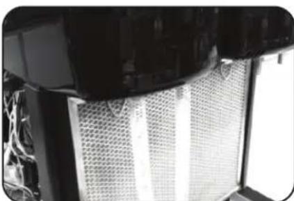
natural_image
Close-up of a mechanical component with mesh pattern and attached circuitry (no visible text or symbols)- Install customer supplied pump system. Turn on pump system and water supply. Check all tubing connections for leaks.
*Water supply line should be 30-80 psi (206.8-551.6 kPa)
*Syrup (Product) line should be 40-80 psi (275.8-551.6 kPa)
NOTE: Flush supply syrup lines with sanitizing solution prior to hooking up to input ports on ULTRA unit.
continued >
INTERNAL BRIXING SYSTEM BRIX ADJUSTMENT INSTRUCTIONS (continued)
- Apply power to machine and turn on by pressing the power button.
- Enter the display menu by pressing the "Gourmet" button for about 5 seconds. Press and release "Gourmet" button to step through the menu to the "Test Refill" screen. Press and release the "Ice" button to select YES.
- The Activate Valve screen will allow you to test the pumping and refill circuit. Press and hold the ULTRA button to activate the left refill system. Confirm that the left side is filling when the ULTRA button is pressed. Release the ULTRA button to stop the filling process. Repeat this process for the right side by pressing the ICE button to test. Check for leaks at the hoses while pumping system is running.
- Run each side until water and product are flowing freely.
- Take a sample from each side (directly from the tubes going into the hopper) to check for proper brix ratio.
- Make adjustments to the brix/ratio by turning the screw/valve adjuster on the water side at the top of the motor cover. Turning the screw clockwise will decrease the water flow. Counter-clockwise will increase the water flow. The flow rate on the syrup side is not adjustable.
- Once the testing is complete, exit the programming menu.
- The auto fill feature can be turned on by pressing the auger button for each side until the display reads "AUGER REFILL ON".
NOTE: Some models also include a “Delay Refill” option. This feature is used to dose in small amounts of new product while delaying between doses. This can help the already frozen product from becoming deluted and not ready to serve. These delay and fill times are to be determined and set based on each application as desired by the end user.
NOTE: Refill system includes a "Maximum Fill Time" in the software. If the time to fill the hopper exceeds this limit, the hopper lights will flash and a "Refill Fault" will be displayed on the screen. If this accurs, check the product supply to ensure the BIB is not empty. (Change BIB if empty). Then press the "ULTRA" button for 3 seconds to clear the fault and restart the refill system.
OPERATING CONTROLS
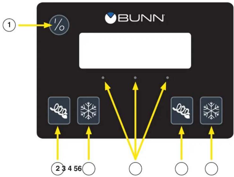
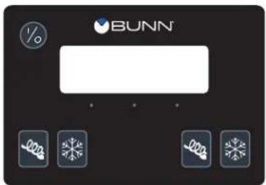
There are five of these switches that will be used for the operation of the dispenser.
flowchart
graph TD
    A["1"] --> B["%"]
    B --> C["BUNN"]
    C --> D["2 3 4 56"]
    C --> E["○"]
    C --> F["○"]
    C --> G["○"]
    C --> H["○"]

- Switch (upper left corner of the control pad)
This switch is the ON/OFF toggle switch which powers up the dispenser and the LCD display. When ON the Date and Time toggle back and forth continuously except during programming.

- (bottom left corner)
This is used to turn the left side auger motor to AUGER ON, AUGER OFF or AUGER REFILL ON. (Refill only applicable when installed)

- (bottom left corner)
This is used to turn the left side ice control to OFF, ICE or CHILL.

- (bottom right corner)
This is used to turn the right side auger motor AUGER ON, AUGER OFF or AUGER REFILL ON. (Refill only applicable when installed)

- (bottom right corner)
This is used to turn the right side ice control to OFF, ICE or CHILL.
- Hidden buttons used for Programming.
USING THE DISPENSER FOR GRANITA-TYPE PRODUCTS
- Lift the lid slightly for the selected hopper and slide back to gain access to the hopper.
- Place the pre-mixed liquid product in the selected hopper.
- Press and release the ON/OFF switch to power on the dispenser.
- Press and release the ON/OFF switch to power on the dispenser.


- Press and release the appropriate (left or right side) ON/OFF switch to start the Auger Motor and to turn on AutoFill when applicable. (See *NOTE)

- Press and release the (OFF/ICE/CHILL) switch and select ICE to begin the cooling process for the selected hopper.
- Wait for the liquid to freeze to the desired consistency.
HINT: BUNN recommends that the product in the dispenser be thawed each day, usually overnight. The ice granules get too large and a consistent product is difficult to maintain if left frozen for an extended period of time. Set the NIGHT mode for a few hours each night and return it to the DAY mode when the product has thawed sufficiently. You'll know it is in the NIGHT mode because the display will indicate NIGHT MODE, and the hopper light(s) will turn off.
USING THE DISPENSER FOR COLD LIQUID PRODUCTS
- Lift the lid slightly for the selected hopper and slide back to gain access to the hopper.
- Place the pre-mixed liquid product in the selected hopper.

- Press and release the ON/OFF switch to power on the dispenser.

- Press and release the appropriate (left or right side) ON/OFF switch to start the Auger Motor and to turn on AutoFill when applicable. (See *NOTE)

- Press and release the (left or right side) OFF/ICE/CHILL switch and select CHILL to begin the cooling process for the selected hopper.
- Wait for the liquid to cool.
*NOTE: Refill system includes a "Maximum Fill Time" in the software. If the time to fill the hopper exceeds this limit, the hopper lights will flash and a "Refill Fault" will be displayed on the screen. If this accurs, check the product supply to ensure the BIB is not empty. (Change BIB if empty). Then press the "ULTRA" button for 3 seconds to clear the fault and restart the refill system.
PROGRAMMING
Using the menu-driven display on the front of the dispenser, the operator has the ability to alter or modify various parameters such as beverage consistency and set day/night “ON/OFF” times. The operator is also prompted to check a variety of periodic service functions or even a step-by-step cleaning routine. There is also the opportunity to return all changes back to factory default settings.
Access to most controls can be password protected to allow only qualified personnel to make changes.
flowchart
graph TD
    A["1"] --> B["%"]
    C["2"] --> D["•"]
    E["3"] --> F["•"]
    G["4"] --> H["•"]
    I["BUNN"] --> J["•"]
    K["•"] --> L["•"]
    M["•"] --> N["•"]
Programming Switches
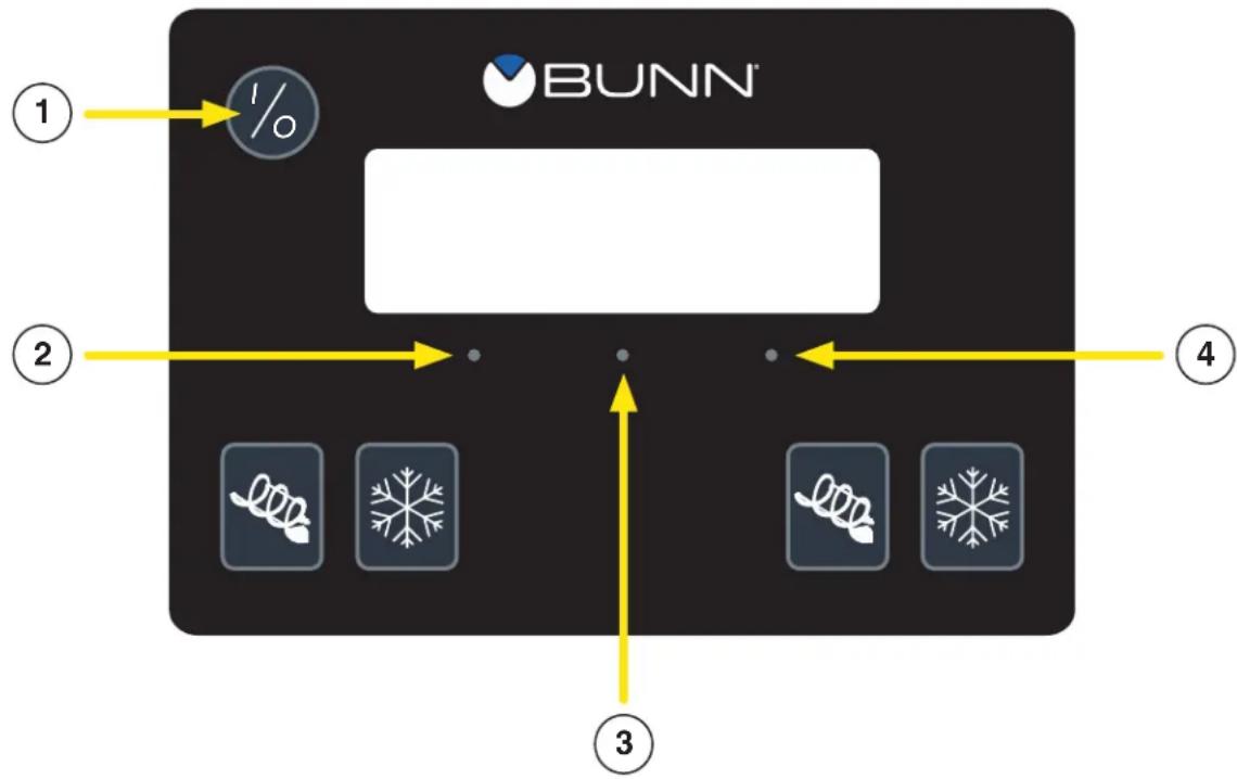
To access the programming mode, and to scroll through the different function screens, hidden programming switches are used. There are three of these switches that will be used for the setup of the dispenser.
- I/O SWITCH (upper left corner of the control pad)
This switch is the ON/OFF toggle switch which powers up the dispenser and the LCD display. This switch is also used as back up switch in menu mode.
- "LEFT DOT" / ULTRA (left under display)
When prompted by a selection from the menu to answer yes or no, the "Left dot" switch is used to answer "NO" or (-) minus.
- "CENTER DOT" / GOURMET (center under display)
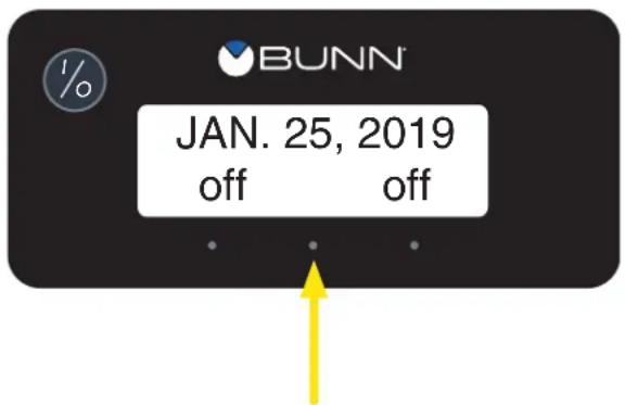
Press and hold this switch 5 seconds to access the Menu Function Index. This switch is also used as "NEXT" to scroll through the functions.
- "RIGHT DOT" / ICE (right under display)
When prompted by a selection from the menu to answer yes or no, the “Right dot” switch is used to answer “YES” or (+) plus.
PROGRAMMING (continued)
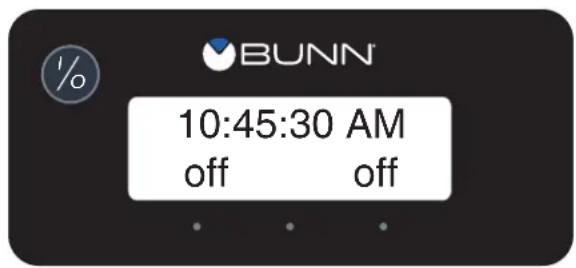
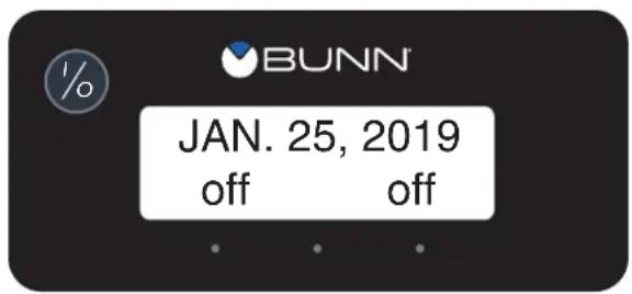
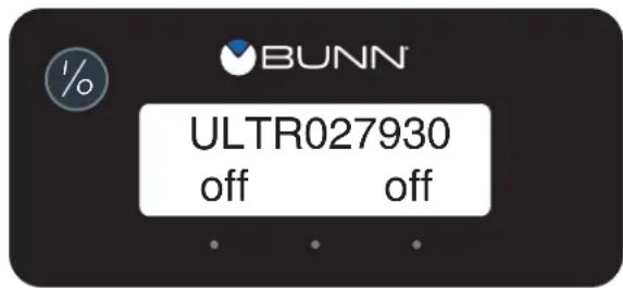
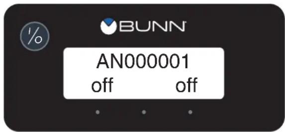
During normal operations, the Date, the Time, and the Serial Number toggle back and forth continuously. The following function screens are in the order they appear from the menu display. Each screen will have instructions and procedures to program the various functions of the dispenser.
Home Screen
Displays the TIME, DATE, SERIAL NUMBER and ASSET NUMBER which toggle back and forth continuously.
Menu Function Index
Press and hold for five seconds the GOURMET hidden switch to enter into the Menu Function Index. The screens on the following page are in order that they appear from the menu display.
- Pressing NO ("ULTRA") or NEXT (GOURMET") will advance to the next function.
- Press ON/OFF ("I/O") will back up to the previous screen. A one minute time out will return to the HOME SCREEN.
continued >
PROGRAMMING (continued)
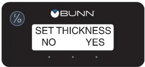
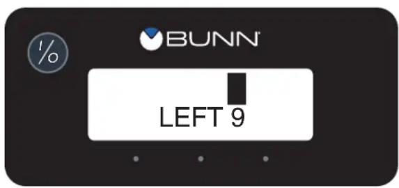
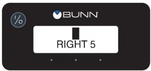
Set Consistency
This function allows the operator to adjust the ice consistency, or torque of each auger when answered YES ("ICE"). Two screens will appear for left and right. The operator can scroll through a range of a minimum of 1 (ULTRA) to a maximum of 16 (ICE). Factory default is 10.
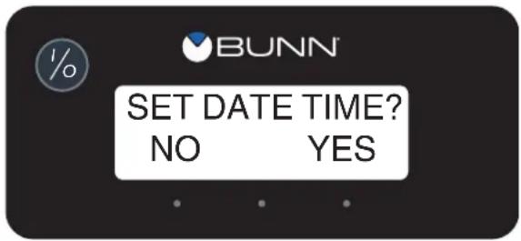
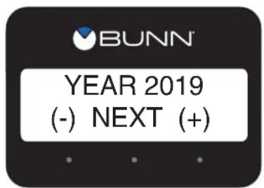
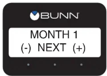
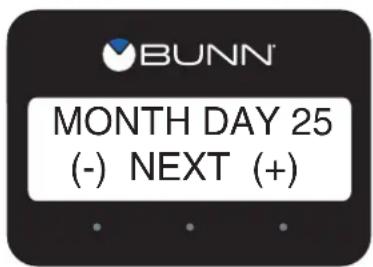
Set Time and Date
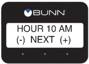
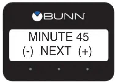
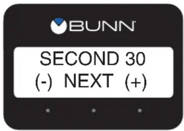
Selecting YES (ICE) allows the operator to set the DATE (YY MM DD) and TIME (HR MIN SEC) for display on the HOME SCREEN.
PROGRAMMING (continued)
Set Night Time/Set Day Time
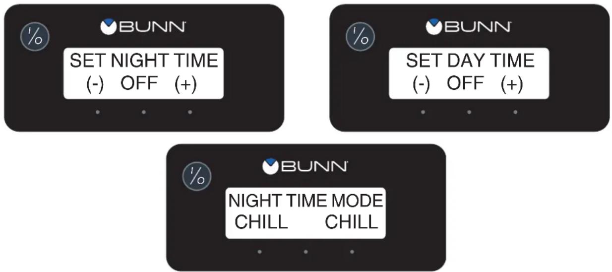
The setting of the Day/Night mode allows the dispenser to “power down” during off hours. The bottom corners displaying “ICE” will change to “CHILL” during the night mode. During the night mode, the product will be kept chilled to below 35^ F. “ICE” reading will return after night mode elapses. With “OFF” representing 12:00 AM, the operator can scroll to the times desired for the night time mode to begin and end.
Install Date
The following three screens will scroll after advancing past the function “Restore Defaults”. The Install Date and Time is recorded when the dispenser is powered on for the first 100 hours. The Install Date and Time cannot be reset and is stored in permanent memory.
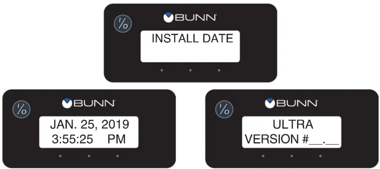
NOTE: Several other menu functions are included in this dispenser. Please refer the PROGRAMMING MANUAL available on the BUNN website at www.bunn.com.
OTHER RECOMMENDATIONS FOR YOUR DISPENSER
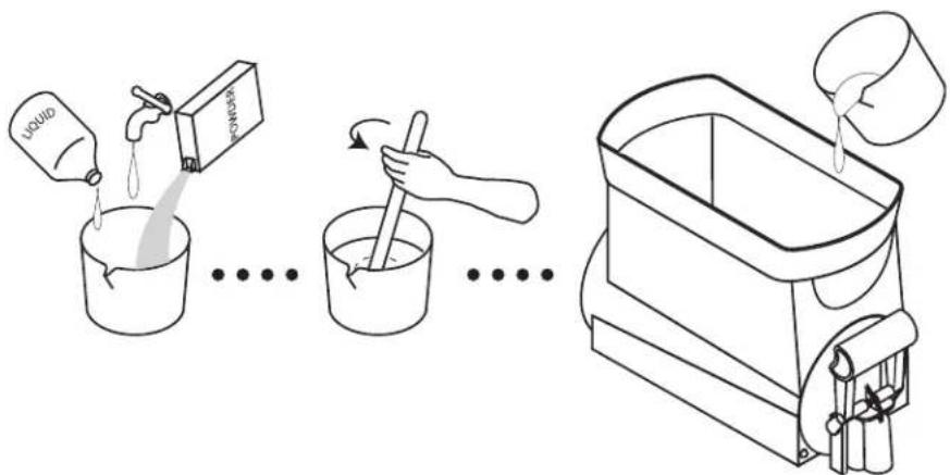
- Whether liquid concentrate or granulated powder, all product must be thoroughly mixed BEFORE adding it to the hoppers.
- For best results with granita-type products, use only products with an apparent brix of 12 or higher. Some products may work with an apparent brix as low as 9. Your experimentation with other products will be the best guide in this area. Using products with a brix lower than 12 may cause physical damage to the equipment drive system.
- Keep the pre-mixed liquid product refrigerated. This reduces cooling/freezing time in the dispenser.
- Keep the hoppers topped-off during peak serving periods. Add pre-mixed liquid product as it is dispensed. This reduces the cooling/freezing time and assures you of always having product ready to dispense.
- Keep the product level in the hoppers higher than the auger. If the auger is exposed, air will become entrapped in the mixture resulting in a clouded foamy consistency. This condition could also cause physical damage to the equipment drive system.
- You may find it beneficial to turn down the ice controls to keep the ice granules from growing too large. Refer to Programming on page 12 for Setting the Consistency.
- Some products freeze at a lower temperature than others. You may notice frost or ice on the hoppers. This is normal and should not be a concern.
- Humidity in the air may cause sweating on the outside surfaces of the hoppers. This is to be expected and should not be a concern. The drip trays beneath the hoppers will capture this and cause it to flow to the lower drip tray for disposal.
- Some noises are to be expected during normal operation of the dispenser. By becoming familiar with the noises made during normal operation, you will be better able to listen for problems.
- Any signage attached to the equipment must not be made with PVC, also known as Vinyl or Polyvinyl Chloride.
PREVENTIVE MAINTENANCE
Bunn-O-Matic ^® Corporation recommends that preventive maintenance be performed at regular intervals. Maintenance should be performed by a qualified service technician.
For Technical Service, contact Bunn-O-Matic ^® Corporation at 1-800-286-6070.
NOTE: Replacement parts or service caused by failure to perform required maintenance is not covered by warranty.
NOTE: Equipment failure caused by product related issues are not covered by warranty.
| CYCLE (Months) | ITEM |
| 6 Replace hopper drum seal | |
| 6 Replace faucet seal | |
| 6 Inspect auger shaft for abnormal wear | |
| 6 Replace the auger shaft bushing | |
| 6 Replace the cooling drum seal | |
| 6 Lubricate the motor shaft and motor shaft groove | |
| Monthly Clean condenser air filter | |
| 6 or less needed Clean condenser coil | |
| 6 or as needed Inspect and clean the condenser fan | |
| 6 Inspect, clean, or replace the hopper tray drain tubes | |
RECOMMENDED CLEANING
Frequency of cleaning should be as directed by the product manufacturer.
- Turn cooling to OFF selection. Empty all product from the hopper(s). Turn auger to OFF selection. Disconnect the hopper lid lamp cord(s) and remove the lids. On models with autofill, disconnect fill hoses and level probe from hopper.
natural_image
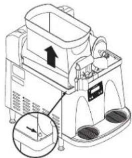
Technical line drawing of a mechanical device with an arrow indicating direction, showing internal components and a close-up inset (no text or symbols)- Depress the hopper lock plunger. Lift the hopper up slightly.
natural_image
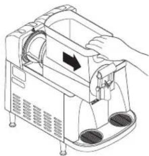
Line drawing of a hand operating a kitchen appliance with a handle and control panel (no text or symbols)- Pull forward to remove.
natural_image
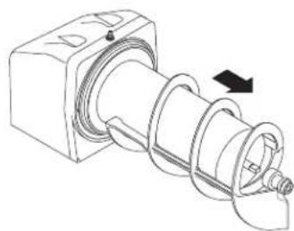
Technical line drawing of a mechanical component with a spiral and threaded shaft (no text or symbols)- Pull the auger from the cooling drum.
natural_image
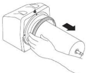
Line drawing of a hand holding a cylindrical device with a scroll wheel, showing motion direction (no text or symbols)- Remove the cooling drum seal from the rear of the drum.
natural_image
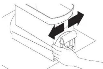
Line drawing of a hand pressing down on a mechanical component with arrows indicating motion (no text or symbols)- CAUTION: The faucet valve is under spring tension. Spread one side of the handle first, then the other and disconnect from the hopper.
natural_image
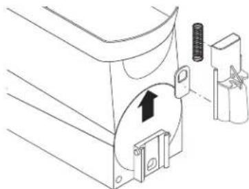
Technical line drawing of a mechanical component with a directional arrow and mounting bracket (no text or symbols)- Carefully slide the faucet valve up to remove the spring and faucet seal. Extra care should be taken when handling the seal to prevent damage. Do not fold the seal as this will cause damage to the Teflon® sealing surface.
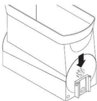
natural_image
Technical line drawing of a mechanical component with a circular dial and arrow indicating direction (no text or symbols)- Remove the auger nose bushing from inside the hopper.
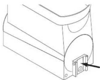
natural_image
Technical line drawing of a mechanical component with a bracket and mounting hole (no text or symbols)-
Care must be taken to ensure this surface does not get scratched during cleaning. Deep scratches could cause leakage around the seal.
-
Place all parts in a clean sink with mild hot water (120°F) and sanitizer solution. Allow all parts to soak for at least 5 minutes. Carefully wash all components with a clean wash cloth in the hot water and sanitizer solution. Use a clean, soft bristle brush as needed for the smaller components and tight areas. Do not immerse hopper lids. Use a commercial sanitizer that has 100 ppm of available chlorine with a concentration level of at least 3% available chlorine (KAY-5 Sanitizer). Follow the sanitizer's mixing instructions to ensure 100 ppm of available chlorine.
-
Wash the drums, hopper drip trays, top covers, and outer enclosure using a clean wash cloth that has been dampened in the hot water and sanitizer solution. Pay particular attention to the shaft area and make sure it is thoroughly cleaned and sanitized.
-
Thoroughly rinse all surfaces with a clean wash cloth that has been dampened with hot water. Wipe dry with a clean dry wash cloth before reassembling the dispenser.
NOTE: Although most parts are dishwasher safe, they may be affected by the chemicals in some commercial sanitizing agents. Do not place the hopper nor hopper lids in a dishwasher. Rinse thoroughly before assembly.
ASSEMBLY FOLLOWING CLEANING
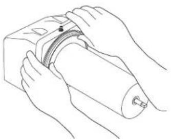
natural_image
Line drawing of hands performing a medical procedure on a cylindrical device (no text or symbols present)- Install the seal(s) over the flange at the rear of the cooling drum(s) and press the seal(s) firmly into place as shown. Apply a small amount of lubricant on seal.
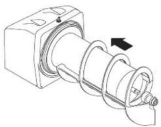
natural_image
Technical line drawing of a mechanical assembly with a spiral component and mounting bracket (no text or symbols)- Align the auger shaft(s) with the auger(s). Push the auger(s) as far as they will go and rotate so the flat face of the auger shaft is aligned with the flat face of the auger nose.
natural_image
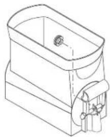
Line drawing of a rectangular container with a side arm and handle (no text or symbols)- Install auger nose bushing into inside front of hopper.
natural_image
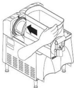
Line drawing of a person operating a device with a circular component and directional arrow (no text or symbols)- Thoroughly rinse the hopper(s) and install over the auger(s) and cooling drum(s).
natural_image
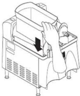
Line drawing of a hand operating a mechanical device with a handle and control panel (no text or symbols)- Slide into place and push down until the hopper lock plunger(s) snap into place. On models with autofill, reconnect fill hoses and level probe to hopper.
natural_image
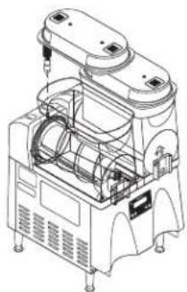
Technical line drawing of a mechanical device with internal components and mounting feet (no text or symbols)- Set the lids on the hopper(s) and plug in the hopper lid lamp cord(s).
natural_image
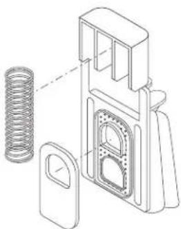
Technical line drawing of a mechanical device with spring and housing (no text or symbols)- Position the faucet seal and return spring in the faucet valve.
natural_image
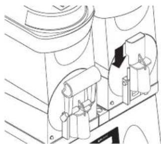
Technical line drawing of a mechanical assembly with rollers and housing (no text or symbols)- Slide the faucet valve assembly into place on the hopper.
natural_image
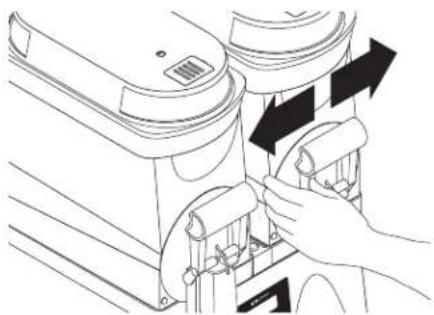
Line drawing of a hand adjusting a mechanical component with arrows indicating motion (no text or symbols)- Press down on the valve to compress the spring. Position the faucet handle over the faucet valve one side at a time and snap into place on the hopper.
natural_image
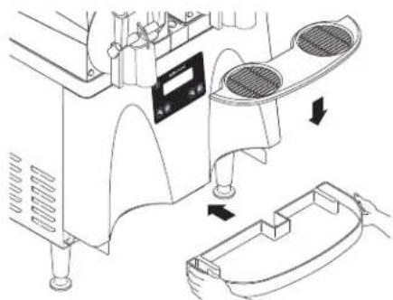
Technical line drawing of a mechanical device with cooling fans and heat exchangers (no text or symbols)- Assemble the drip tray.
- Turn ON augers and cooling function to desired settings.
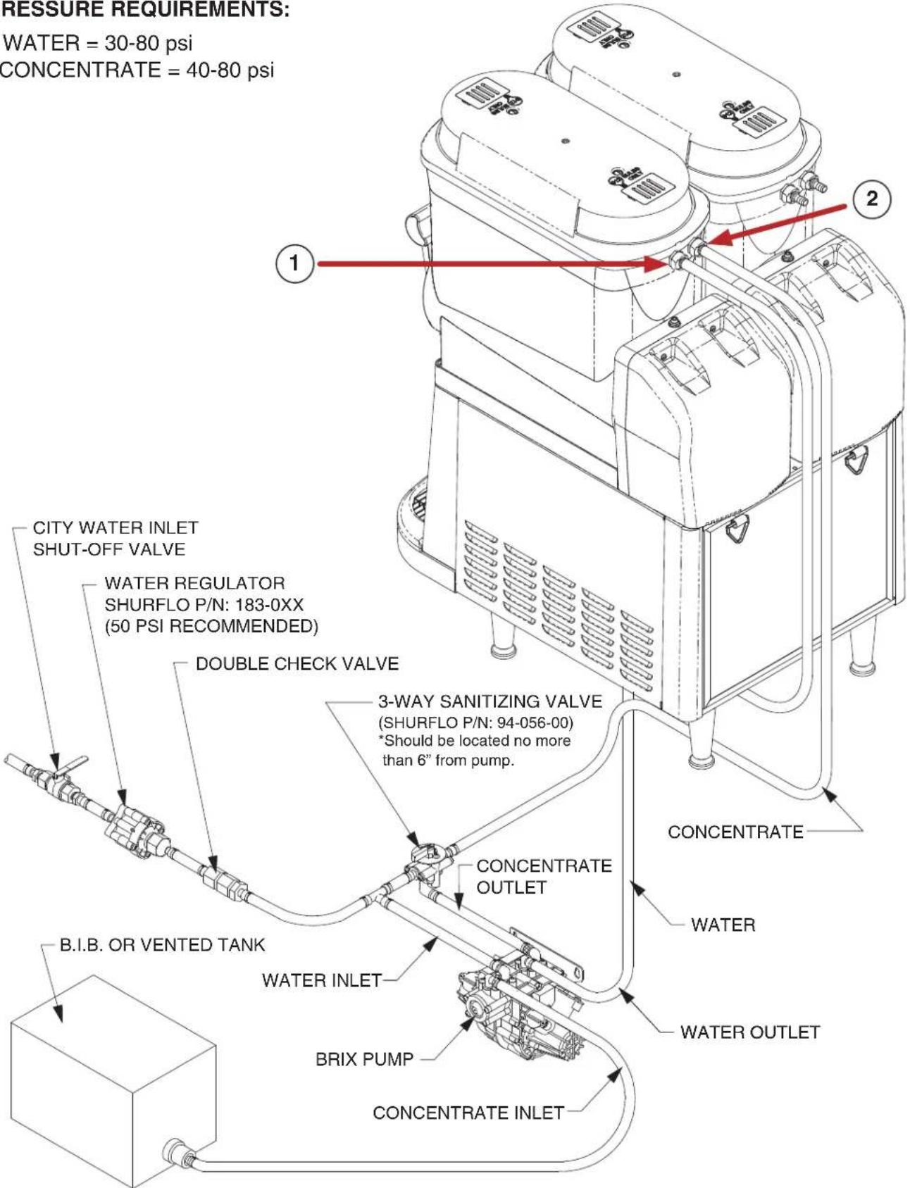
AUTOFILL INSTALLATION INSTRUCTIONS
- Connect the water line to the water fitting in the ULTRA hopper.
- Connect the concentrate line from the syrup pump to the product fitting in the ULTRA hopper.
PRESSURE REQUIREMENTS:
WATER = 30-80 psi CONCENTRATE = 40-80 psi
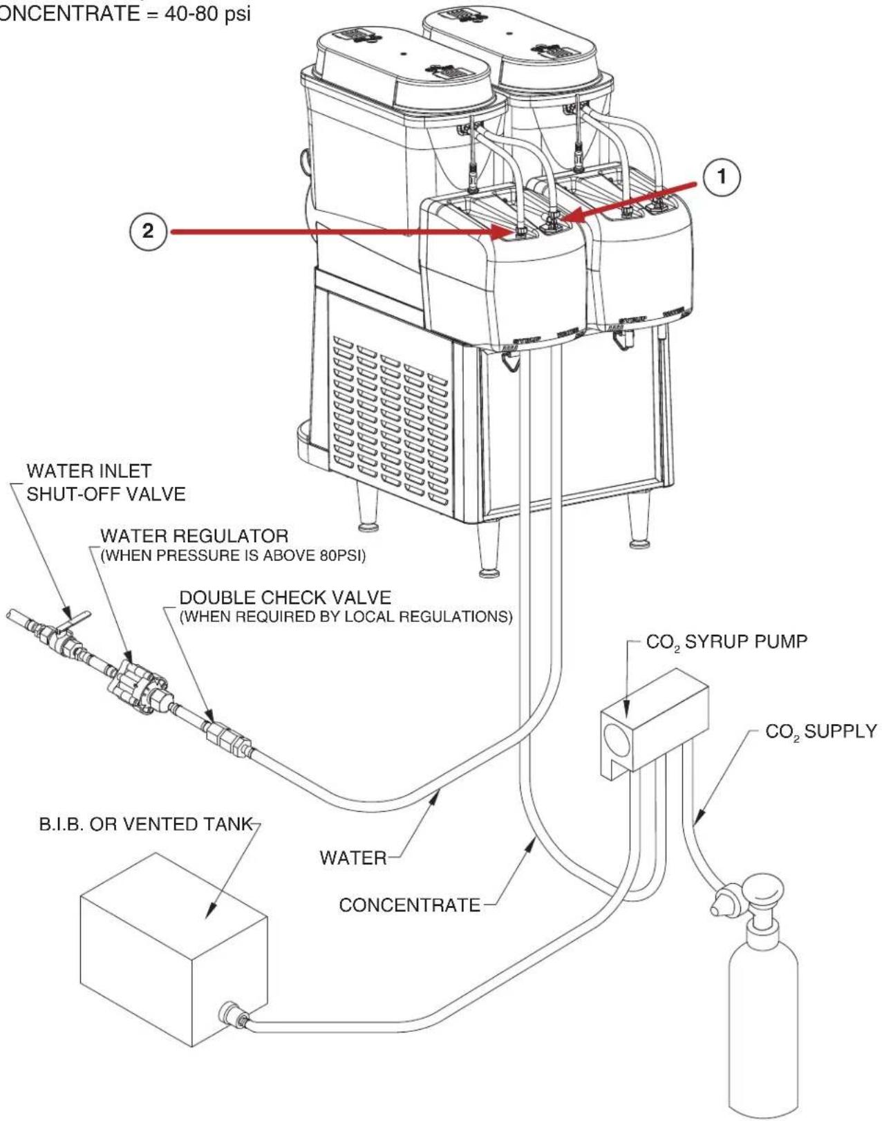
CF AUTOFILL INSTALLATION INSTRUCTIONS
- Connect the water line to the water fitting in the ULTRA motor cover.
- Connect the concentrate line from the syrup pump to the product fitting in the ULTRA motor cover.
PRESSURE REQUIREMENTS:
WATER = 30-80 psi
CONCENTRATE = 40-80 psi
AUTO-FILL CLEANING INSTRUCTIONS
(WITH BRIXING PUMP INSTALLED)
Materials required
- Non-sudsing liquid detergent (such as common household automatic dishwasher liquid detergent).
- Household bleach (Sodium chloride solution: 5.25%) or equivalent.
- Clean five (5) gallon bucket.
- Measuring Cup
- An adaptor is needed to hold the Q.C.D. (Quick Connect/Disconnect) fitting on the concentrate suction line open. A connector from an empty bag will work.
Sanitizing Procedure
- Fill bucket with 4 gallons of warm water (120-180 deg. F).
- Measure 4 ounces (1/2 cup) of the liquid detergent and add to the water.
- Measure 2 ounces (1/4 cup) of bleach and add to the water, then stir, mixing evenly.
- Ensure that the refill for the Ultra hopper is turned off.
- Empty all product from the Ultra hopper
- Disconnect the concentrate line from the B-I-B and install adaptor on the quick disconnect so the line is open to the sanitizing solution. Place concentrate inlet line into the bucket so that the Q.C.D. will stay at the bottom.
- Press the auger button to turn on the "Auger Refill On" feature.
- Allow system to run until the hopper is about 1/4 full then turn off refill.
- Switch three way sanitize valve to the Sanitize position.
- Turn refill system back on and let run until the hopper is almost full then turn off refill.
- Allow sanitizer to sit in system for 10 minutes.
- Drain sanitizer from hopper and remove the Q.C.D. from the sanitizer bucket.
- Empty remaining sanitizer and refill bucket with about 2 gallons of warm (120-180 deg. F) rinse water.
- Turn sanitize valve back to dispense position.
- Place Q.C.D. into rinse water and turn on refill system.
- Run until hopper is about 1/4 full.
- Turn off refill system and drain hoppers.
- Refer to the RECOMMENDED CLEANING instructions and follow these steps to clean the hopper, lid and other dispense parts.
AUTO-FILL SANITIZING INSTRUCTIONS
(WITH INTERNAL BRIXING SYSTEM INSTALLED)
- Fill bucket with 4 gallons of 120 Degree F water and sanitizing solution to equal 100 ppm of available chlorine.
NOTE: Some installations may require more sanitizer solution to fill the supply lines completely.
-
Select "auger on" and set the cooling mode to "off" for each hopper being sanitized.
-
Empty product from each hopper being sanitized.
-
Pour one gallon of warm water into each hopper to rinse the remaining product, and then drain hopper(s).
-
Disconnect concentrate line from the B-I-B and set so the sanitizer can flow freely through it. Place the connector in the bottom of the sanitizer solution bucket.
-
Select "auger refill on" for each hopper being sanitized. Allow hoppers to fill until system reaches the fill probe. If a refill fault occurs, press the Ultra button to clear and continue filling. Repeat this process until the product line runs clear.
NOTE: You may need to drain the hopper again and allow filling until the product line runs clear, indicating sanitizer has completely filled the lines. If the delay refill system is activated, you may also need to turn the auger off, then back to “auger refill on” to fill the hopper without the delay.
-
Once full, allow sanitizer to sit in the hopper(s) for 10 minutes.
-
Select "auger off" for each hopper being sanitized. Drain the sanitizer from the hopper(s).
-
Remove the B-I-B connector(s) from the sanitizer bucket and reconnect to the product B-I-B(s).
-
Refer to the RECOMMENDED CLEANING instructions of this manual and follow the steps to remove, clean and sanitize the hopper(s), lid(s) and other dispense parts.
-
Select “auger refill on” for each hopper being sanitized and allow to run until product starts flowing into the hopper(s).
-
Select "auger off" for each hopper being sanitized, then drain hopper(s).
-
The dispenser is now ready to be turned on and filled for use.
- INSTALLATION & OPERATING GUIDE
- BUNN-O-MATIC COMMERCIAL PRODUCT WARRANTY
- INTRODUCTION
- CONTENTS
- SITE PREPARATION
- NORTH AMERICAN REQUIREMENTS
- CE REQUIREMENTS
- USER NOTICES
- ELECTRICAL REQUIREMENTS
- & 220-240 Volt AC Models
- INITIAL SETUP
- INITIAL SETUP (continued)
- HANDLE INSTALLATION INSTRUCTIONS
- INTERNAL BRIXING SYSTEM BRIX ADJUSTMENT INSTRUCTIONS
- INTERNAL BRIXING SYSTEM BRIX ADJUSTMENT INSTRUCTIONS (continued)
- OPERATING CONTROLS
- USING THE DISPENSER FOR GRANITA-TYPE PRODUCTS
- USING THE DISPENSER FOR COLD LIQUID PRODUCTS
- PROGRAMMING
- Programming Switches
- PROGRAMMING (continued)
- Home Screen
- Menu Function Index
- Set Consistency
- Set Time and Date
- Set Night Time/Set Day Time
- Install Date
- PREVENTIVE MAINTENANCE
- RECOMMENDED CLEANING
- Frequency of cleaning should be as directed by the product manufacturer.
- ASSEMBLY FOLLOWING CLEANING
- AUTOFILL INSTALLATION INSTRUCTIONS
- CF AUTOFILL INSTALLATION INSTRUCTIONS
- PRESSURE REQUIREMENTS:
- AUTO-FILL CLEANING INSTRUCTIONS
- (WITH BRIXING PUMP INSTALLED)
- Materials required
- Sanitizing Procedure
- AUTO-FILL SANITIZING INSTRUCTIONS
- (WITH INTERNAL BRIXING SYSTEM INSTALLED)
Brand : Bunn
Model : ULTRA-2A R452
Category : Water dispenser