
SD8 - Blender SAMSON - Free user manual and instructions
Find the device manual for free SD8 SAMSON in PDF.


| Product Type | Stereo Mixer Amplifier |
| Brand | Samson |
| Model | SD8 |
| Dimensions (W x D x H) | 482 x 280 x 178 mm (19 x 11 x 7 in) |
| Weight | 34.8 lb (15.8 kg) |
| Power Requirements | 115 V AC 60 Hz (UL/CSA), 230/240 V AC 50/60 Hz (BSI/Central Europe), 100 V AC 50/60 Hz (Japan) |
| Power Consumption | 982 W |
| Amplifier Power | 250 W per channel into 4 ohms (less than 1% THD) |
| Number of Input Channels | 8 (each with mic XLR and line 1/4" TRS) |
| Additional Input | CD/Tape via RCA phono jacks |
| Graphic Equalizer | 10-band, ±12 dB boost/cut (32 Hz to 16 kHz) |
| Channel EQ | 3-band: High (10 kHz) ±15 dB, Mid (800 Hz) ±12 dB, Low (80 Hz) ±15 dB |
| Built-in DSP | Zoom Digital Signal Processor with 16 presets and 16 variations each (256 effects) |
| Phantom Power | 48V, switchable for all mic inputs |
| Aux Sends | 2: Send 1 (pre-fade, pre-EQ) and Send 2 (post-fade, post-EQ) |
| Aux Returns | 2 (Return 1 hard left, Return 2 hard right) |
| Monitor Output | 1/4" unbalanced, independent monitor mix |
| Headphone Output | 1/4" stereo, 20 mW into 8 ohms |
| Speaker Outputs | 4x 1/4" jacks (2 left, 2 right), minimum 4 ohms |
| Protection Relay | Mutes outputs during power on/off to prevent thumps |
| Rack Mounting | 19" standard, 4 rack spaces, rack ears supplied |
| Frequency Response | 20 Hz - 50 kHz (±3 dB) |
| Total Harmonic Distortion | <0.1% (typical 0.02%) |
| Signal-to-Noise Ratio | >105 dB (amp section, A-weighted) |
Frequently Asked Questions - SD8 SAMSON
User questions about SD8 SAMSON
0 question about this device. Answer the ones you know or ask your own.
Ask a new question about this device
Download the instructions for your Blender in PDF format for free! Find your manual SD8 - SAMSON and take your electronic device back in hand. On this page are published all the documents necessary for the use of your device. SD8 by SAMSON.
USER MANUAL SD8 SAMSON
Produced by On The Right Wavelength for Samson Technologies Corp.
Copyright 1997, Samson Technologies Corp.
Printed March 1997
Samson Technologies Corp.
575 Underhill Blvd.
P.O. Box 9031
Syosset, NY 11791-9031
Phone: 1-800-3-SAMSON (1-800-372-6766)
Fax: 516-364-3888
Introduction 1
SD8 Features 2
Guided Tour 4
Overview 4
Channel 5
Main Section 7
Rear Panel 9
Connecting The SD8 - General Suggestions 11
Setting Up and Using the SD8 12
Setting the Correct Gain Structure 13
Suggested Performance Application 15
Grounding Techniques 16
Using Equalization 17
Using The Aux Sends and Returns and Monitor Output 19
Using the Internal Digital Signal Processor (DSP) 20
Table of SD8 Effects 21
Specifications 22
Introduction
Congratulations—you've made an excellent choice in your purchase of the Samson SD8 Stereo Mixer Amplifier! In this manual, we'll take you on a guided tour through all the features of this powerful and flexible device, and we'll tell you how to get the most out of the SD8. Although designed for easy operation, we suggest you take some time out first to go through these pages so you can fully understand how we've implemented a number of unique features.
The SD8 combines a flexible multi-channel stereo mixer with a clean, powerful 250 watt per channel amplifier, 10-band graphic equalizer, and a Zoom digital multi-effects processor—all in a single compact chassis that mounts easily in any standard 19" rack. Simply plug in your microphones and line-level instruments (such as keyboards, tape decks, CD players, etc.), connect the SD8 to any standard loudspeakers, and you've got a complete PA system suitable for use in small clubs or similar environments, or in permanent installations such as churches or conference rooms.
In these pages, we'll begin with an overview of the main SD8 features, followed by a guided tour of the front and rear panels. Then we'll describe the various input and output connections (including wiring diagrams) and tell you in detail how to set up your SD8 and how best to use the unit in live performance. Finally, we'll cover a number of specific topics (such as grounding techniques, using equalization and auxiliary sends and returns, and details about the onboard multi-effects processor) and then wrap things up with full specifications. You'll also find a warranty card enclosed—please don't forget to fill it out and mail it so that you can receive online technical support and so we can send you updated information about this and other Samson products in the future.
SPECIAL NOTE: Should your unit ever require servicing, a Return Authorization number (RA) is necessary. Without this number, the unit will not be accepted. Please call Samson at 1-800-372-6766 for a Return Authorization number prior to shipping your unit. Please retain the original packing materials and, if possible, return the unit in its original carton and packing materials.
The Samson SD8 utilizes state-of-the-art technology in integrated mixer/amplifier design. Here are some of its main features:
- Convenient carrying handle and supplied standard 19" rack ears (the SD8 takes just four rack spaces) allows easy integration into any setup.
- Eight independent channels, with both mic and line inputs for each channel. This allows you to blend together a variety of source signals, including dynamic or condenser microphones, keyboards, CD/tape players, etc. Standard XLR mic connectors (for microphone inputs) and electronically balanced 1/4" jacks (for line-level inputs) are provided for each channel; in addition, there is a dedicated stereo CD/Tape input that provides dual phono (RCA) jacks.
- Full stereo control, with continuously adjustable Pan controls for each channel that enable you to place each input signal independently in the left-right plane.
- Power to spare—a full 250 watts per channel into four ohms. Any standard speaker cabinets (four, eight, or sixteen ohms) can be connected to the four rear-panel 1/4" speaker output jacks.
- A built-in Zoom Digital Signal Processor allows you to add a wide variety of professional-quality effects without having to use an expensive external signal processor. A front-panel DSP Mix Level control allows you to precisely define the amount of effects to be blended into the signal.
- Independent three-band equalization for each channel, enabling you to shape the sound of your input signal sources. In addition, a ten-band graphic master equalizer allows you to "tune" the output of the SD8 to the particular room environment you are in. This can be particularly useful for eliminating ringing or feedback problems.
- Continuously adjustable wide-range input Trim and Level controls for each channel allow you to precisely set the correct input and output gain structure.
- Peak LEDs for each channel show you at a glance when an input signal is on the verge of overloading. Other front-panel LEDs show the current status of the amplifier's protection relay circuitry and whether or not phantom power is being applied to attached microphones.
- Two Aux sends per channel (one pre-fade and the other post-fade) allow you to route multiple signals to the internal DSP, to a dedicated Monitor output, or to external signal processors. The Monitor output enables you to set up an onstage monitor mix that is independent of the main house mix. A separate Monitor level control is provided on the front panel.
- Two Aux returns—with a dedicated front-panel Aux return level control—give you the ability to blend in the return signal from external signal processors or other line-level devices without having to utilize input channels.
- A phantom power switch enables you to use the SD8 with high-quality condenser microphones or active DI boxes. When turned on, 48 volts of phantom power is provided to the mic connectors of all input channels.
SD8 Features
- Protection relay circuitry prevents “thumps” when powering on or off. This means that you can use the SD8 with a single power strip into which other audio devices are connected, without danger of damage to connected speakers.
- A rear-panel amplifier input allows you to bring external signals from other mixers or audio devices into the SD8 power amplifier.
- A rear-panel preamplifier output allows you to connect the SD8 to external power amplifiers when higher power ratings are required and/or when additional amplifier feeds are necessary.
- A built-in headphone amplifier, complete with a front-panel 1/4" stereo connector and dedicated level control, allows you to monitor your main mix.
- A convenient front-panel meter that allows you to see at a glance the continuous output signal level.
We'll elaborate on many of these terms and features later in this manual. Now it's time to take a guided tour of the SD8.
Guided Tour - Overview
The following illustration shows an overview of the front panel of the SD8:

Channels
Main Section
Guided Tour - Channel
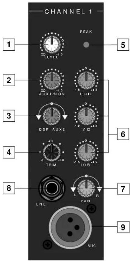
1: Level (white) - This knob determines the final signal level being sent by a channel to the main speaker outputs. In practice, this will be used to adjust the levels of the various signals being blended together by the SD8. The "0" position indicates unity gain (no level attenuation or boost). Turning the Level control clockwise from the "0" position (towards the "10" position) causes the signal to be boosted by as much as 10 dB. Turning it counterclockwise from "0" (towards the "∞" position) causes the signal to be attenuated (when fully counterclockwise, the signal is attenuated infinitely—in other words, there is no sound). For best signal-to-noise ratio, all channel level controls should be kept at or near the 0 level.
2: Aux 1 / Monitor (violet) - This knob allows you to send signal from one or more channels to the SD8's monophonic Monitor output or to an external device connected to the Aux Send 1 output jack on the rear panel. This send is pre-fade; that is, the level of the signal is determined solely by the channel's input Trim (see #4 below), and is unaffected by its EQ settings and the position of its Level control. At the "0" position, the signal is routed with unity gain (that is, no boost or attenuation). As each Aux 1 / Monitor knob is turned clockwise from the "0" position (towards the "10" position), the signal is boosted by as much as 10 dB; as it is turned counterclockwise from the 0 position (towards the "∞" position), the signal is attenuated. When turned fully counterclockwise, the signal is attenuated infinitely—in other words, no signal is routed. For more information, see the "Using Aux Sends and Returns" section on page 19 of this manual.
3: DSP / Aux 2 (violet) - This knob allows you to send signal from one or more channels to the SD8's internal Zoom Digital Signal Processor (DSP) or to an external device connected to the Aux Send 2 output jack on the rear panel. This effects send is post-fade; that is, the level of the signal is determined by the channel's input Trim (see #4 below), its EQ settings (see #6 below), and the position of its Level control. At the 12 o'clock position, there is no signal routed. As the DSP / Aux 2 knob is turned clockwise (towards "Aux 2"), signal is routed increasingly to Aux Send 2. As the DSP / Aux 2 knob is turned counterclockwise (towards "DSP"), signal is routed increasingly to the internal Zoom Digital Signal Processor. For more information, see the "Using Aux Sends and Returns" section on page 19 of this manual and the "Using the Internal DSP" section on page 20 of this manual.
4: Trim (black) - This knob allows you to set the input gain of the connected mic or line signal over an exceptionally wide range. Continuously adjustable from -6 dB to -50 dB, the input gain is raised when the Trim knob is turned clockwise and attenuated when it is turned counterclockwise. For information on how to use this, see the "Setting The Correct Gain Structure" on page 13 in this manual.
5: Peak LED (red) - This warning light indicates an overload situation. It lights whenever a channel's signal is 5 dB short of clipping. To stop it from lighting (and to eliminate the accompanying sonic distortion), turn down the channel's input Trim knob (see #4 above) or reduce the amount of equalization boost (see #6 on the next page).
6: Equalizer (blue) - These knobs determine the amount of boost or attenuation in each of three frequency areas. The high and low frequency knobs provide 15 dB of cut or boost at 10 kHz and 80 Hz, respectively, with shelving-type control. The mid frequency knob provides 12 dB of cut or boost at 800 Hz, with a bell (peaking) curve. A center detent in each knob (at the 12 o'clock position) indicates no boost or attenuation (that is, flat response). As each knob is turned clockwise from the center detent position, the frequency area is boosted; as it is turned counterclockwise from the center detent position, the frequency area is attenuated. For more information, see the "Using Equalization" section on page 17 of this manual.
7: Pan (green) - This knob allows you to place the input signal anywhere in the left-right stereo spectrum, while keeping the overall signal level constant. When the knob is placed at its center (detented) position, the signal is sent equally to both left and right outputs. When moved left of center, less signal is sent to the right output and more signal is sent to the left output, making the sound appear left of center; when moved right of center, less signal is sent to the left output and more signal is sent to the right output, making the sound appear right of center. To route a signal hard left or right, place the pan knob either fully counterclockwise or fully clockwise.
8: Line input connector - Connect line-level sources (such as synthesizers, drum machines, CD players, tape decks, or effects processors) to any of the SD8's eight channels using this electronically balanced 1/4" jack (balanced or unbalanced signals can be accepted here). WARNING: Do not connect a channel's line input if you already have something connected to its microphone input; each channel is designed to accept only one source or the other.
9: Mic input connector - Connect a microphone to any of the SD8's eight channels using this standard XLR jack. This jack is intended to accept signal from low-level, low-impedance mics but can also be used to accept signal from other sources (such as direct injection boxes) if the input Trim control is turned down (see #4 on the previous page). WARNING: Do not turn the SD8's Phantom power on if signal sources other than condenser microphones (or active direct injection boxes requiring 48 volts of power) are connected to any of these inputs (for more information, see #3 on page 9). Also, do not connect a channel's microphone input if you already have something connected to its line input; each channel is designed to accept only one source or the other.
Guided Tour - Main Section
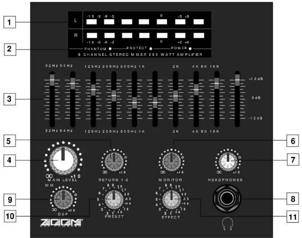
1: Meter - This seven-segment bar meter shows the continuous output level of the SD8. For optimum signal-to-noise ratio, try to adjust all Levels (channel and main) so that program material is usually at or around 0 VU, with occasional but not steady excursions to the +3 segment. See the "Setting Up and Using the SD8" section on page 12 in this manual for more information.
2: Status LEDs - These show the status of various conditions within the SD8. The leftmost LED (labeled "Phantom") lights steadily red when Phantom power is being supplied to all mic inputs (see #3 on page 9 in this manual). The center LED (labeled "Protect") lights yellow for approximately five seconds whenever the SD8 is powered on and lights steadily whenever there is a potentially dangerous overheating situation. It indicates the activity of the built-in protection relay circuitry during which time 0 volts DC are provided to all connected speakers, thus preventing any "thump." The rightmost LED (labeled "Power") lights steadily green whenever the SD8 is powered on and fades slowly when the unit is powered off.
3: Ten-Band Graphic Master EQ - These sliders allow you to add 12 dB of boost or attenuation to ten different frequency areas, affecting the main output signal of the SD8. When a slider is at its center detented ("0 dB") position, the selected frequency area is unaffected (it is said to be flat). When a slider is moved up (above the "0 db" position, towards the "+12 dB" position), the selected frequency area is boosted, and when it is moved down (below the "0 dB" position, towards the "-12 dB" position), the selected frequency area is attenuated. For more information, see the "Using Equalization" section on page 17 in this manual.
Guided Tour - Main Section
4: Main Level (white) - This knob determines the final signal level sent to the speaker output jacks on the rear panel. You can think of this as being the "master fader"—and we made this knob extra big so you won't miss it even under low-light performance conditions. At its fully counterclockwise ("∞") position, the signal is infinitely attenuated—that is, there is no sound. At its 2 o'clock position, the SD8 mixer section is at unity gain and is providing no attenuation or boost to the output signal. At its fully clockwise ("0") position, the maximum amount of gain is being added by the SD8 mixer section to the output signal. For more information, see the "Setting The Correct Gain Structure" section on page 13 in this manual.
5: Return 1-2 Level (violet) - This knob determines the input level of signal arriving via Aux returns 1 and 2 (see #4 on page 9), with Aux return 1 automatically panned hard left and Aux return 2 automatically panned hard right. This signal is at unity gain (no boost or attenuation) when the knob set to the "0" position. Turning the knob clockwise from the "0" position (towards the "10" position) causes the return signal to be boosted by as much as 10 dB. Turning it counterclockwise from "0" (towards the "∞" position) causes the return signal to be attenuated (when fully counterclockwise, the signal is attenuated infinitely—in other words, there is no return signal). For information on how to properly set this, see the "Setting Up and Using the SD8" section on page 12 and "Using the Aux Sends and Returns" section on page 19 in this manual.
6: Monitor Level (violet) - This knob determines the overall level of the signal being output from the rear panel Monitor jack. This signal is at unity gain (no boost or attenuation) when the knob set to the "0" position. Turning the knob clockwise from the "0" position (towards the "10" position) causes the Monitor signal to be boosted by as much as 10 dB. Turning it counterclockwise from "0" (towards the "∞" position) causes the Monitor signal to be attenuated (when fully counterclockwise, the signal is attenuated infinitely—in other words, there is no Monitor signal sent). For more information, see the "Using the Aux Sends and Returns" section on page 19 in this manual.
7: Headphone Level (white) - This knob sets the level of the signal sent to the headphone jack (see #8 below). WARNING: To avoid possible damage to connected headphones (or, worse yet, to your ears!), always turn this all the way off (to the fully counterclockwise “∞” position) before plugging in a pair of headphones—then raise the level slowly while listening. Changing the Headphone Level has no effect on any other output levels.
8: Headphone jack - Connect any standard stereo headphones to this jack (via a standard 1/4" TRS plug) for private monitoring of the final output signal. NOTE: The SD8 main speaker outputs are not muted when headphones are inserted into the Headphone jack—to monitor your main mix in privacy, set the Main Level control to its fully counterclockwise ("∞") position. The built-in SD8 headphone amplifier delivers 20 mW into 8 ohms.
9: DSP Mix Level - Determines the level of "wet" signal returning from the onboard Zoom Digital Signal Processor. Wet signal is returning at unity gain (that is, with no boost or attenuation) when the knob set to the "0" position. Turning the knob clockwise from the "0" position (towards the "10" position) causes the wet signal to be boosted by as much as 10 dB. Turning it counterclockwise from "0" (towards the "∞" position) causes the wet signal to be attenuated (when fully counterclockwise, the wet signal is attenuated infinitely—in other words, there is no return from the DSP—you'll hear the signal completely "dry"). For more information, see the "Using the Internal Digital Signal Processor" section on page 20 of this manual.
10: Preset (1 - 16) - Allows you to select any of 16 preset effect types for the onboard Zoom DSP. For more information, see the "Using the Internal Digital Signal Processor" section on page 20 of this manual.
11: Effect (1 - 16) - Allows you to select any of 16 variations on the preset effect type selected for the onboard Zoom DSP (see #10 above). For more information, see the "Using the Onboard Digital Signal Processor" section on page 20 of this manual.
Guided Tour - Rear Panel

1: Power switch - As you may have guessed, this is what you use to turn the SD8 on and off. The built-in protection relay circuitry (which mutes the outputs for approximately five seconds after powering on) prevents power-on "thumping," which can potentially damage connected speakers.
- AC input - Connect the supplied standard 3-pin "IEC" plug here.
3: Phantom switch - When this switch is pressed in, the SD8 delivers 48 volts of phantom power to pins 2 and 3 of all XLR microphone connectors in all eight channels. WARNING: Only use this switch with the SD8 powered down. Before turning phantom power on, be sure to disconnect all non-microphone signal sources (such as passive direct injection boxes) from the XLR mic jacks. Although phantom power will have no adverse effect on connected dynamic microphones, it should be used only when one or more condenser microphones are connected to the SD8. Refer to the owners manual of your microphone or active direct injection (DI) box to determine whether or not it requires 48 volts phantom power—Samson cannot assume responsibility if you damage a mic or DI box by incorrectly applying phantom power from the SD8. If you're not completely certain that one or more connected mics or active DI boxes require 48 volts phantom power, leave this switch off (its out position).
4: Aux Returns 1 - 2 - These unbalanced inputs allow you to route signal from external devices such as effects processors to the Aux Return knob on the front panel of the SD8 (see #5 on page 8). Because the SD8 is a stereo system, the signal arriving at Aux return 1 is automatically panned hard left and the signal arriving at Aux return 2 is automatically panned hard right. See the "Using the Aux Sends and Returns" section on page 19 in this manual for more information.
Guided Tour - Rear Panel
5: Aux Sends 1 - 2 - These unbalanced outputs allow you to route signal from each of the two discrete Effects Sends to external devices such as effects processors. Aux Send 1 is pre-fade and pre-EQ, while Aux Send 2 is post-fade and post-EQ. See the "Using the Aux Sends and Returns" section on page 19 in this manual for more information.
6: Pre Out (L, R) - These two unbalanced outputs provide a stereo line-level output from the SD8 mixer section; they are normally used to connect the unit to self-powered speakers or to an external power amplifier and speakers where additional power is required or where additional amplifier feeds are necessary. The Pre outputs are not affected by the ten-band graphic master equalizer but are affected by the SD8's Main Level control.
7: Amp In (L, R) - These two unbalanced inputs allow you to connect any external stereo line-level signal directly to the SD8 power amplifier. When connection is made to either of these jacks, the internal connection between the SD8 mixer and SD8 power amplifier is broken, and all channel inputs are muted. The Amp inputs are not affected by either the ten-band graphic master equalizer or the SD8's Main Level control. The Amp In jacks can optionally also be used as insert patch points as follows:
- Ring - A preamp output which is affected by both the ten-band graphic master equalizer and the SD8's Main Level control.
- Tip - An amp input which is not affected by either the ten-band graphic master equalizer or the SD8's Main Level control.
For more information about the use of the Amp In jacks as insert patch points, contact Samson Technical Support (1-800-372-6766) between 9 AM and 5 PM EST.
8: Monitor Out - This unbalanced output provides a monophonic line-level output, affected by the front panel Monitor level control (see #6 on page 8) but unaffected by the Main Level control (see #4 on page 8). It is normally used to connect the unit to an external monitor mixer/amplifier/speaker system so that the performers can receive an onstage monitor mix independent of the house mix. See the "Using the Aux Sends and Returns" section on page 19 of this manual for more information.
9: Speaker Outputs - These are the SD8's main outputs; use these four unbalanced jacks (two of which carry the left signal and two of which carry the right) to connect the SD8 to loudspeakers rated at 4 ohms or greater (that is, 4, 8, or 16 ohms). The lower the ohm rating, the greater the power output. We recommend the use of 4 ohm speakers for long-term usage. The SD8 delivers 250 watts of power per channel into 4 ohms at less than 1% THD (Total Harmonic Distortion). In order to ensure correct phase correlation, the tip of the SD8 speaker jack should be connected to the "+" (hot) input of your loudspeaker, and the sleeve of the SD8 speaker jack should be connected to the "-" (ground) input of your loudspeaker.
10: CD/Tape In - Use these dual RCA input jacks to connect the output from a CD or tape player to the SD8. When connected, the stereo signal appears at Channels 7 and 8, at unity gain (the Trim control for those channels will have no effect), mixed in with any mic or line signal connected to those channels. From there, the signals can be panned as required, equalized if necessary, and routed to either Aux send (for routing to connected external processors), to the internal DSP, and/or to the Monitor output.
11: Heat sink - Make sure this anodized aluminum heat sink is unobstructed when the SD8 is powered on. In particular, we recommend that you keep the rear of the rack open in order to release heat. If your rack does not have a removable rear, space should be left open on the front of the rack cabinet, especially immediately above the SD8—remember, heat rises!
12: Carrying handle - Use this convenient carrying handle whenever transporting the SD8. Alternatively, the SD8 can be mounted in any standard 19" rack (taking just four spaces) by removing this handle and installing the supplied rack ears.
Connecting The SD8 - General Suggestions
The actual connections you'll make to and from the SD8 will vary according to the environment you use it in and the particular equipment you have. However, here are a few basic rules concerning connections that will apply in pretty much all situations:
- In general, it's best to make all connections with the SD8 turned off—this particularly applies to speaker connections. If you must make connections with the power on, make sure that the Main Level control is completely down (turn the knob fully counterclockwise). Before powering down, turn the Main Level control completely down.
- When using line inputs, try to use balanced connectors and cabling wherever possible. These kind of connections do a better job of rejecting extraneous noise and hum and generally provide a cleaner signal. If your equipment doesn't provide balanced outputs, however, not to worry: All SD8 channel line inputs will accept either balanced or unbalanced connectors. The diagram below shows how balanced 1/4" TRS (Tip/Ring/Sleeve) connectors should be wired:

Unbalanced cables use standard 1/4" phone connectors, wired as follows:

- Make one connection at a time and then monitor the incoming signal. If you hear a distinct hum or buzz, you may have a grounding problem with that particular device. See the “Grounding Techniques” section on page 16 in this manual for information on how to avoid grounding problems.
- NEVER connect a microphone and line level input to the same channel simultaneously—use one or the other. You can have some channels connected to microphones and others to line level signals (for example, you might want to plug mics into channels 1 - 4 and line level signals into the remaining channels)—just don't have both kinds of inputs connected to the same channel. The diagram below shows how your mic connectors should be wired:

Setting Up and Using the SD8
Setting up your SD8 is a simple procedure which takes only a few minutes:
- Remove all packing materials (save them in case of need for future service) and decide where the SD8 is to be physically placed—if desired, remove the carrying handle and install the supplied rack ears so that it can be mounted in any standard 19" rack (it requires four rack spaces). Be careful when handling the SD8—the rear heat sink fins and side rack panels have sharp edges. Make sure that the rear heat sink fins are unobstructed and that there is good ventilation around the entire unit. If the SD8 is mounted in a rack that contains multiple amplifiers, we recommend that you avoid potential overheating problems by using spacer panels to ensure that the amps are not directly on top of one another—remember, heat rises!
- Before even plugging the SD8 into an AC socket, begin by making its speaker connections. It is never a good idea to power up any amplifier that is not connected to loudspeakers. Any loudspeakers with a minimum impedance load of 4 ohms (that is, 4 ohms or greater) can be used, but we recommend the use of 4 ohm speakers for long-term usage. In order to ensure correct phase correlation, be sure that the connection from the tip of the SD8 speaker jack goes to the "+" (hot) input of your loudspeaker, and that the sleeve of the SD8 speaker jack is connected to the "-" (ground) input of your loudspeaker.
- Next, make the signal input connections to the mic or line inputs of the various channels. WARNING: Do not connect a channel's line input if you already have something connected to its microphone input, or vice versa; each channel is designed to accept only one source or the other.
- Turn all channel Trim and Level controls as well as the Main Level control fully counterclockwise, to their “∞” setting. Set the rear-panel Phantom switch to its “off” (out) position unless you are absolutely certain that all connected microphones require 48 volt phantom power; if so, set the Phantom switch to its “on” (in) position.
- Plug the unit into any grounded AC socket using the supplied IEC cord. Because of the special relay protection circuitry built into the SD8, you can even plug it into the same power strip that other audio devices are connected to. You can then turn on all devices at once with the single power strip on-off switch, with no danger of damaging connected speakers by generating "thumps."
- Press the rear panel Power switch in order to turn on the unit. The Protection LED will go on for approximately five seconds, and then switch off (you'll hear a click when it does).

flowchart
graph TD
    A["Speaker 1"] --> B["Central Device"]
    C["Speaker 2"] --> B
    D["Speaker 3"] --> B
    B --> E["Speaker 4"]
    style A fill:#f9f,stroke:#333
    style C fill:#f9f,stroke:#333
    style D fill:#f9f,stroke:#333
    style B fill:#ccf,stroke:#333
Setting the Correct Gain Structure
You're now ready to establish the correct gain structure—the key to getting the best performance from the SD8, or from any mixer, for that matter. This is a simple procedure that ensures optimum input and output levels so that no unnecessary noise (caused by too low a signal) or overload distortion (caused by too high a signal) is created. Here's a step-by-step description of how to do so:
a. With all connections made (as described above) but with the power off, start by setting all channel Level controls fully counterclockwise (to their “∞” position), and then set the Main Level knob to its “0” position.
b. Set all channel input Trim knobs to their fully counterclockwise (-6) position.
c. Set all channel equalizer knobs to their center detent "0" positions and set the ten-band graphic master equalizer completely flat (all sliders at their center detent "0" positions).
d. Set all channel Aux 1 / Monitor send knobs and the main section Aux return Level knob to their fully counterclockwise ("∞") position. Set all channel DSP / Aux 2 knobs to their center detented 12 o'clock position and set the main section DSP Mix Level knob to its fully counterclockwise ("∞") position.
e. Turn on all devices connected to channel line inputs and Aux returns and set their level controls to unity gain or, if there is no unity gain indicated on their output control, to maximum. If you've got outboard effects processors connected to the Aux returns, make sure they are sending completely "wet" (processed) signal, with no "dry" (unprocessed) signal mixed in.
f. If condenser microphones are connected to the SD8, turn on the Phantom switch.* Finally, turn on the SD8's main power.
g. Play an instrument connected to one of the SD8's line inputs** and, while doing so, raise the corresponding channel Level control to the "0" position. You should see the segment meter begin to move—adjust the input Trim control for that channel so that the "0" segment lights frequently and the "+3" segment lights only occasionally. The Peak LED for that channel should not flash at even the highest level input signals. If the incoming signal seems too hot even with the input channel Trim all the way at its minimum (-6) setting, you may need to lower the output level of the instrument, though this will rarely occur. Conversely, if the signal is too low even with the input channel trim all the way up, something's definitely wrong: in all likelihood, the connecting audio cable is faulty.
h. Once you've set the optimum level in step (g) above, continue playing the instrument and slowly raise the main Level knob until you reach the desired listening level.
i. Repeat step (g) above for each instrument connected to the SD8 channel line inputs.
* CAUTION: Before turning phantom power on, be sure to verify that all connected mic(s) and/or active DI boxes require 48 volts. Also, disconnect all other signal sources (such as passive DI boxes) from the XLR mic jacks.
** If you're using an instrument such as electric guitar or bass, connect it to the SD8 with a direct injection box to ensure correct impedance.
Setting the Correct Gain Structure
j. The procedure for setting optimum microphone levels is virtually identical; sing or speak into the mic at the level you expect to use in performance while slowly raising the Level control for that channel to its "0" position. Then adjust the input Trim control for that channel while watching the segment meter and Peak LED. You should expect that microphone inputs will require rather more in the way of input Trim boost than line inputs.
k. The general idea behind using the internal DSP is to drive it as hot as possible (short of overloading it) and to then use the DSP Mix Level control to carefully set the amount of processed signal you want to hear. Begin by selecting Preset 1, Effect 1 (this is a general Hall reverb) for the DSP—the DSP Mix Level control should still be at its fully counterclockwise “∞” position, as specified in step (d) above. Using a channel that has already had its gain structure adjusted in step (g) or (j) above, turn the DSP / Aux 2 knob for that channel to its fully counterclockwise “DSP” position. Play the instrument (or sing into the microphone) connected to that channel while slowly turning the DSP Mix Level knob clockwise until you hear the desired amount of processed signal added to the dry signal. If you hear any distortion, lower the amount of signal being sent to the DSP by turning that channel’s DSP / Aux 2 knob clockwise (towards its center detented “off” position. For more information, see the “Using the Internal Digital Signal Processor” section on page 20 in this manual.
I. If you have any outboard signal processors connected to the Aux send jacks on the rear panel, follow this step. Because outboard effects processors can sometimes be quite noisy, it's particularly important to maximize the amount of signal being sent to them via the SD8 Aux sends. As with the internal DSP, the idea is to drive these devices as hot as possible (short of overloading them) and then to use the Aux return Level to carefully adjust the amount of processed signal being blended with the dry signal. To set optimum Aux send levels, use a channel that has already had its gain structure adjusted in step (g) or (j) above. Turn the Aux send 1 / Monitor knob for that channel to its "0" (unity gain) position and then play the instrument (or sing into the microphone) connected to that channel. Adjust the input levels of connected outboard effects processors so that their meter shows incoming signal normally in the 0 vu range (with just occasional higher excursions). Then it's time to optimize the Aux return Level. While continuing to play your instrument (or continuing to sing into the microphone), slowly raise the Aux return Level control until you hear the desired amount of processed signal added to the dry signal. Repeat for any external device connected to the Aux 2 send jack. For more information, see the "Using the Aux Sends and Returns" section on page 19 in this manual.
m. The gain structure is now correctly set—you've optimized the level of all signals coming into and out of the SD8, and the end result will be minimum noise and distortion and maximum clean sound. You'll now find that the majority of your mixes can be accomplished with most channel Level controls at or near their 0 (unity gain) position and that the channel peak LEDs rarely if ever light (remember, if they do light, it means that something is distorting!). If you need to make adjustments to the overall level, use the main Level control.
If you encounter difficulty with any aspect of setting up or using your SD8, you can call Samson Technical Support (1-800-372-6766) between 9 AM and 5 PM EST.
Suggested Performance Application
The following illustration shows the basic interconnections between an SD8 and external equipment when used in a typical live performance application:

flowchart
graph TD
    A["Speaker 1"] -->|MIC 1| B["Audio System"]
    C["Speaker 2"] -->|MIC 2| B
    D["MIDI TONE GENERATOR"] -->|LINE 3| E["CD OR DAT"]
    F["MIDI KEYBOARD"] -->|LINE 4| E
    G["SIGNAL PROCESSOR"] --> H["Audio System"]
    I["SAVSON SDB STEREO"] --> J["L"]
    I --> K["R"]
    L["Speaker 3"] --> M["Audio System"]
    N["Speaker 4"] --> O["Audio System"]
The main connections here involve connecting the SD8 speaker outputs to PA speakers and the Monitor output to the input of an external amplifier driving onstage monitors. Various microphones and line level signals are connected to channel mic and line inputs and a CD or tape player is connected to the CD/Tape input. An external signal processor is connected to Aux Send 2, with the resulting processed signal returned to Aux Returns 1 and 2.
Grounding Techniques
Hum and buzz are the biggest enemies you face when interconnecting a large number of different pieces of equipment to a central audio mixer. This is because each piece of equipment may operate at a marginally different voltage (this difference is called potential) and, when two devices at slightly different potential are physically connected with audio cabling, the end result can be nasty, extraneous noise (mind you, connecting two devices at very different potential can result in a major electrical shock!).
However, there are several steps you can take to avoid grounding problems. First, assuming you have an isolated electrical circuit that can handle the electrical demands of your mixer and all connected audio equipment (these needs will usually be modest), you should always plug your mixer and all connected equipment into the same circuit. If possible, nothing else but this equipment should be connected to that circuit. If you can't do this, at least avoid plugging your mixer and audio equipment into the same circuit that is already powering things like heavy machinery, air conditioners, heaters, refrigerators, washing machines, neon signs or fluorescent light fixtures. One particular culprit that will almost certainly create problems is the standard light dimmer (the kind that uses silicon controlled rectifiers). Where low-level lighting is desired, use incandescent fixtures with autotransformer-type dimmers (sometimes called Variacs) instead—these cost considerably more than the standard dimmer you'll find at your local hardware store, but are well worth the extra expense.
Three-prong plugs (such as the one used by the SD8) should always be used as is; don't use adapters to lift the ground (unless you're using a "star ground network"—see below). If you hear hum or buzz from a device that uses a two-prong plug (or an external two-prong AC/DC adapter), you can try reversing the plug in the socket. If that doesn't work, you may need to physically ground that device's chassis by connecting a wire (called a strap) from it to a grounded piece of metal. Some pieces of equipment have a screw-type ground post to which the strap can be connected; if not, you can attach some kind of metallic binding post to the case itself. If you are using rack-mounted audio devices and are experiencing hum or buzz, there's a simple test to determine the source of the problem: while keeping all devices powered on and connected with audio cabling, physically remove each device, one by one, from the rack. If the hum disappears when a particular device is removed, you'll know that that device is probably the culprit.
We also recommend that you use balanced audio cabling and connectors wherever possible. The SD8 provides electronically balanced connectors for all mic and line channel inputs. The wiring diagram in the “Connecting The SD8” section on page 11 of this manual shows how XLR and 1/4" TRS (Tip/Ring/Sleeve) connectors should be wired for use with these inputs.
In addition, you can minimize possible interference by planning your audio, electrical, and computer cable runs so that they are as far apart from one another as possible and so they don't run parallel to one another. If they have to cross, try to ensure that they do so at a 90^ angle (that is, perpendicular to one another). In particular, try to keep audio cabling away from external AC/DC adapters
If you're using the SD8 or in a fixed location such as a recording studio, you may want to invest the time and money into creating a star ground network. This is by far the best technique for avoiding grounding problems. It involves using a formidable ground source such as a cold water pipe or a copper spike driven into the earth. A thick grounding cable is connected to that source and is then brought to a central distribution point; from there, individual cables are connected to each piece of equipment. This setup also requires that you lift the ground plug of all three-prong AC connectors, so there is the possibility of danger if it is done incorrectly. We strongly recommend that you contract with a qualified professional to carry out this or any kind of electrical work.
Another, less common problem you may encounter is that of oscillation (a ringing tone), which, apart from being annoying, is potentially dangerous to your speakers. This is generally caused either by poor outside wiring or by returning a signal out of phase (most commonly from an outboard signal processor). If audible oscillation occurs, try isolating each input signal by turning down all other inputs. If one signal alone is causing the problem, you should be able to eliminate the oscillation by reversing that signal's phase (many signal processors have a switch that allows you to do this).
Using Equalization

One of the most exciting aspects to using a mixer such as the SD8 is having the ability to shape a sound, using a process called equalization. But there are few areas of audio engineering more misunderstood than equalization, and, just as good EQ can really help a sound, bad EQ can really hurt it, so read on...
Every naturally occurring sound consists of a broad range of pitches, or frequencies, combined together in a unique way. This blend is what gives every sound its distinctive tonal color. The EQ section in a mixer allows you to alter a sound by boosting or attenuating specific frequency areas. The SD8 provides a ten-band graphic master equalizer (more about this shortly) as well as independent three-band equalization for each channel, with center frequency areas of, from high to low: 10 kHz, 800 Hz, and 80 Hz. Each channel EQ knob is labeled with the maximum amount of cut or boost provided ( ± 15 db in the case of the high and low frequencies and ± 12 db in the case of the mid frequency).
We provided these particular frequency areas because they have maximum impact on musical signals—that's why they are sometimes known as “sweet spots.” When an EQ knob is in its center detented position (“0”), it is having no effect. When it is moved right of center, the particular frequency area is being boosted; when it is moved left of center, the frequency area is being attenuated. The high and low EQ controls employ what is known as a shelving curve (where frequencies either above or below the specified area are affected) while the mid frequency control employs what is known as a bell curve (where frequencies both above and below the specified area are affected).

Ten-band graphic master equalizer
The ten-band graphic master equalizer affects the overall output signal of the SD8. Its main function is to allow you to "tune" the device to the particular room environment you are in. Perhaps its most important job is to enable you to eliminate ringing or feedback problems caused when a microphone is too close to a loudspeaker. To accomplish this, start with all ten bands flat (that is, all ten sliders at their detented "0" center position). Then, one by one, raise each slider until you hear the feedback or ringing markedly increase. This allows you to identify the problematic frequency area (it will most commonly be one or more of the high mid-range or high frequency areas). When you've located the problem area(s), it's simply a matter of lowering that slider or sliders below the 0 point until the ringing or feedback disappears. Don't lower the frequency area any further than you need to, or the quality of the overall sound may suffer. If you don't specifically need to utilize the SD8's ten-band graphic master equalizer in a particular environment, leave it completely flat (all sliders at their center detented "0" position).
Using Equalization
In most instances, the best way to approach equalization is to think in terms of which frequency areas you need to attenuate, as opposed to which ones you need to boost. (Boosting a frequency area also has the effect of boosting the overall signal; too much EQ boost can actually cause overload—with the accompanying Peak LED warning!) Be aware of the phenomenon of masking, where loud sounds in one frequency range obscure softer sounds in the same range; by cutting EQ “notches” in a loud signal, you can actually make room for a softer one to shine through. And try not to think of EQ as a miracle worker—no amount of equalization can put a singer in tune or remove the distortion from an overloaded input signal! The key is to get the signal right in the first place, by using correct gain structure and mic placement.
Although the specific EQ you will apply to a channel signal is very much a matter of personal taste, here are a few general suggestions: Boosting the low frequency of instruments such as bass drums or bass guitar will add warmth and make the sound "fatter"; conversely, you may want to attenuate the low frequency component of instruments such as cymbals, high-hats, and shakers so as to "thin" them out. The mid-range control is particularly effective for vocals—attenuating it can give a vocal performance more of an "FM-radio" feel and boosting it can help a vocal cut through dense instrumentation. Be careful not to boost high frequencies too much or you risk adding hiss to the signal, though just a touch can help add "shimmer" to an acoustic guitar, ride cymbal, or high-hat.
Using The Aux Sends and Returns and Monitor Output

Aux Send 1 / Monitor knob

DSP / Aux Send 2 knob

Aux Send jacks

Aux Return jacks

Aux Return knob

Monitor output jack
Monitor Level knob
The two Aux sends provided by the SD8 allow you to combine the signal from multiple channels and send the resulting mix to the rear panel Monitor output jack, to the internal Zoom Digital Signal Processor (DSP), or to external devices such as effects processors.
The Aux 1 / Monitor send knob works as follows: when it is at the "0" position, the signal is routed with unity gain (that is, no boost or attenuation). As it is turned clockwise from the "0" position, the signal is boosted; as it is turned counterclockwise from the "0" position, it is attenuated. Aux send 1 is pre-fade; that is, the level of the signal is determined solely by the input trim and is unaffected by the EQ settings or the position of the channel level control.
The DSP/Aux 2 send knob works differently: At the 12 o'clock position, there is no signal routed. As it is turned clockwise (towards "Aux 2"), signal is routed increasingly to Aux Send 2. As it is turned counterclockwise (towards "DSP"), signal is routed increasingly to the internal Zoom Digital Signal Processor. In contrast to Aux send 1, this Aux send is post-fade; that is, the level of the signal is determined by the input trim, the EQ settings, and the position of the channel level control (raising or lowering the level of the channel will affect the send level as well). It is particularly important to keep this distinction in mind when you connect external signal processors to the SD8 via either or both of the two Aux Send jacks on the rear panel.
In addition, the SD8 provides two Aux returns, controlled by a single knob in the Main section. These returns allow you to bring in signal from outboard devices, either as a stereo pair or dual monophonically (many popular effects processors provide a single mono input but a stereo output). Because the SD8 is a stereo device, Aux return 1 is automatically panned hard left and Aux return 2 is automatically panned hard right. This signal is at unity gain (no boost or attenuation) when the Aux return knob set to the "0" position. Turning the knob clockwise from the "0" position (towards the "10" position) causes the Aux return signal to be boosted by as much as 10 dB. Turning it counterclockwise from "0" (towards the "∞" position) causes the return signal to be attenuated (when fully counterclockwise, the signal is attenuated infinitely—in other words, there is no return signal).
Using the Monitor Output
In live performance, it is usually desirable to have onstage monitor speakers that allow the performer to clearly hear the music being played. Often, however, the performer requires a different mix than that being sent to the house speakers. The SD8 Monitor output accommodates this need. A separate output jack on the rear panel allows an independent Monitor mix (sometimes called a submix) to be routed to an external amplifier/speaker system. The blend of sounds sent to the Monitor mix is controlled by the Aux 1 / Monitor send knob for each channel, with the master Monitor mix volume controlled by the main section Monitor Level knob. Because this aux send is pre-fade, the Monitor mix is completely independent of the Main Level control setting, the 10-band graphic master EQ setting, the individual channel levels, and the individual channel EQ settings.
Using the Internal Digital Signal Processor (DSP)
There's probably no better way to enhance audio than with the judicious use of effects such as reverb and echo. The SD8 has its own built-in Digital Signal Processor (DSP) chip which provides some of the best effects around. These are some of the same effects, in fact, that you'll find in the highly acclaimed Zoom Studio 1202 signal processor.
As discussed in the “Using The Aux Sends and Returns” section on page 19 in this manual, each SD8 channel has its own discrete DSP/ Aux 2 send knob. This allows effects to be applied only to certain signals and not just to the overall mix (applying effects to the overall mix could make for a muddy sound). As each channel’s DSP/ Aux 2 send knob is turned counterclockwise (towards “DSP”), signal from that channel is routed increasingly to the internal DSP.

To return signal from the internal DSP, use the DSP Mix Level knob in the SD8 main section (as described on page 8 of this manual). When set to the fully counterclockwise ("∞") position, no signal is returned from the DSP, so you'll hear only "dry" signal. Turning the knob clockwise will cause more and more DSP ("wet") signal to be added to the overall mix. When set to the fully clockwise (+10") position, the wet signal is boosted by 10 dB. Wet signal is returning at unity gain (that is, with no boost or attenuation) when the knob set to the "0" position. For best signal-to-noise ratio, you should use the DSP/Aux 2 send knobs to drive the DSP as hot as possible (short of overloading it) and then use the DSP Mix Level knob to carefully set the amount of processed signal you want to hear.
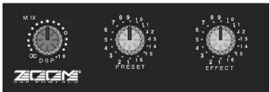
The SD8 provides 16 preset effect types (selected with the main section Preset knob), and 16 variations for each preset (selected with the main section Effect knob), making for a grand total of 256 different reverbs, delays and echoes—all available at the touch of a knob. For each Preset, Effect 1 provides a “standard” setting—that is, a variation that is deemed as being most characteristic of that Preset type. To quickly audition all the SD8 Presets, simply leave the Effect knob at “1” and rotate the Preset knob through its 16 different positions. For unusual custom effects, change the Effect setting.
The chart on the following page lists each Preset as well as describing the sonic variation caused by the different Effect settings
Table of SD8 Effects
| Preset # | Description Effect settings | |
| 1 | Hall reverb - simulates a medium-sized concert hall Larger effect values increase the reverb time, from 1.0 second (Effect 2) to 3.8 seconds (Effect 16). | Alter the reverb time. Effect 1 (standard) is 2.2 seconds. |
| 2 | Room reverb - simulates an acoustically dead space Larger effect values increase the reverb time, from such as a rehearsal studio 0.5 seconds (Effect 2) to 3.3 seconds (Effect 16). | Alter the reverb time. Effect 1 (standard) is 0.7 seconds. |
| 3 | Plate reverb - simulates the effect of a bass-rich plate Larger effect values increase the reverb time, from 3.0 seconds (Effect 2) to 9.0 seconds (Effect 16). | Alter the reverb time. Effect 1 (standard) is 4.2 seconds. |
| 4 | Vocal reverb - a reverb specially designed to Larger Effect values increase the reverb time, from enhance vocals 1.7 seconds (Effect 2) to 4.5 seconds (Effect 16). | Alter the reverb time. Effect 1 (standard) is 4.5 seconds. |
| 5 | Ambience - a reverb specially designed to Larger Effect values increase the reverb time, from add brightness and depth | Alter the reverb time. Effect 1 (standard) is 1.2 seconds. |
| 0.6 seconds (Effect 2) to 3.4 seconds (Effect 16). | ||
| 6 | Orchestral - a reverb with a very wide spread and distinct body | Alter the reverb time. Effect 1 (standard) is 1.5 seconds. Larger Effect values increase the reverb time, from 0.5 seconds (Effect 2) to 3.3 seconds (Effect 16). |
| 7 | Session - simulates a small, acoustically live room | Alter the reverb time. Effect 1 (standard) is 1.0 seconds. Larger Effect values increase the reverb time, from 0.6 seconds (Effect 2) to 3.4 seconds (Effect 16). |
| 8 | Studio - simulates a large studio with a high ceiling | Alter the reverb time. Effect 1 (standard) is 0.9 seconds. Larger Effect values increase the reverb time, from 0.5 seconds (Effect 2) to 3.3 seconds (Effect 16) |
| 9 | Percussion - a reverb specially designed to Larger Effect values increase the reverb time, from enhance percussion | Alter the reverb time. Effect 1 (standard) is 1.8 seconds. |
| 0.6 seconds (Effect 2) to 3.4 seconds (Effect 16). | ||
| 10 | Drums - a reverb specially designed to add body to snare drums | Alter the reverb time. Effect 1 (standard) is 1.7 seconds. Larger Effect values increase the reverb time, from 0.5 seconds (Effect 2) to 3.3 seconds (Effect 16). |
| 11 | Solo - a reverb with a pronounced predelay, well Larger Effect values increase the reverb time, from suited for reed instruments | Alter the reverb time. Effect 1 (standard) is 3.5 seconds. |
| 2.3 seconds (Effect 2) to more than 25 seconds (Effect 16). | ||
| 12 | Gate - an intense, short gated reverb | Alter the gate time. Effect 1 (standard) is 448 milliseconds. Larger Effect values increase the gate time, from 88 milliseconds (Effect 2) to 1.152 seconds (Effect 16). |
| 13 | Power - a short gated reverb good for creating a heavy power sound | Alter the gate time. Effect 1 (standard) is 312 milliseconds. Larger Effect values increase the gate time, from 88 milliseconds (Effect 2) to 1.152 seconds (Effect 16). |
| 14 | Reverse - simulates the effect of a tape recording played backwards | Alter the gate time. Effect 1 (standard) is 858 milliseconds. Larger Effect values increase the gate time, from 88 milliseconds (Effect 2) to 1.152 seconds (Effect 16). |
| 15 | Delay - a long stereo delay (up to 740 ms), with varied amounts of cross-feedback between the left and right channels | Effect 1 (standard) uses delay times of 185 ms (left) and 173 ms (right). Effects 2 through 8 have different feedback amounts and increased delay times from 0.4 to 180 msec. Effects 9 through 16 have different feedback amounts and increased delay times from 11 to 370 msec. |
| 16 | Echo - a fully discrete two-channel echo with varied amounts of feedback | Effect 1 (standard) uses delay times of 173 ms (left) and 185 ms (right). Effects 2 through 8 have different feedback amounts and increased delay times from 0.4 to 180 msec. Effects 9 through 16 have different feedback amounts and increased delay times from 11 to 370 msec. |
Mixer / Pre Amp Section:
Normal Limit
Frequency Response (± 3 dB)
Mic to Pre Out DC \~ 65 kHz 20 Hz - 50 kHz
Line to Pre Out DC \~ 58 kHz 20 Hz - 50 kHz
Aux Return to Pre Out DC \~ 70 kHz 20 Hz - 50 kHz
Total Harmonic Distortion
(20 Hz to 20 kHz, with 30 kHz LPF, trim center)
Mic to Pre Out (Trim Max) 0.060% 0.10% Max
Line to Pre Out (Trim Min) 0.015% 0.03% Max
Aux Return to Pre Out 0.008% 0.03% Max
Signal To Noise Ratio (with 30 kHz LPF)
Mic @ -50dBu input, Trim Max 70 dB 65 dB Min
Mic @ -6 dBu input, Trim Min 90 dB 85 dB Min
Maximum Voltage Gain (dB @ 1 kHz)
Mic to Pre Out (Trim Min/Max) 20 / 64 dB
Line to Pre Out (Trim Min/Max) 0 / 44 dB
Aux Return to Pre Out 10 dB
Tape In to Pre Out 14 dB
Mic to Aux Send 1 (Trim Min/Max) 20 / 64 dB
Mic to Aux Send 2 (Trim Min/Max) 30 / 74 dB
Mic to Monitor Out (Trim Min/Max) 30 / 74 dB
Residual Noise at Pre Out (with 30 kHz LPF, EQ center, Trim Min)
Main Mix -102 dBu
Main Mix with all channel Level Min- 83 dBu -78 dBu
Main Mix with all channel Level Max -71 dBu -65 dBu
Crosstalk (@ 1 kHz with EQ center)
Channel vs. channel 83 dB 80 dB Min
Input vs. output 84 dB 80 dB Min
Tone Control
High (10 kHz) ±12 dB ±15 dB Max
Mid (800 Hz) ±12 dB
Low (80 Hz) ±12 dB ±15 dB Max
Graphic Equalizer
(32, 64, 125, 250, 500 Hz, 1, 2, 4, 8, 16 kHz) ±12 dB
Effect Presets
Hall, Room, Plate, Vocal,
Ambience, Orchestral,
Session, Studio, Percussion,
Drums, Solo, Gate, Power,
Reverse, Delay, Echo
(16 Effect variations per Preset)
Peak LED
5 dB before clipping
Headphone
20 mW (8 ohms)
Specifications
Power Amp Section:
Normal Limit
Rated Output Power (per channel)
(1% THD @ 1 kHz stereo, 4 ohm) 275 watt 250 watt Min
Maximum Voltage Gain
Amp In to Speaker Out (@ 1 kHz) 27.5 dB 28 dB ±
Total Harmonic Distortion (20 Hz to 20 kHz with 30 kHz LPF)
0.02% 0.1% Max
Frequency Response ( ±3 dB) DC \~ 130 kHz 20 \~ 50 kHz
Signal To Noise Ratio (with 30 kHz LPF) 112 dB 105 dB Min
Residual Noise ((with 30 kHz LPF) -84 dBu -80 dBu Max
Idle Current across Emitter Resistor) 6 mA 15 mA Max
DC Offset Voltage +5 mV ±30 mV Max
General:
Dimensions (W x D x H) 482 x 280 x 178 mm
19 x 11 x 7 in
Weight 34.8 lb · 15.8 kg
Power Requirements
115 V ac 60 Hz for UL and CSA Version
230/240 V ac 50/60 Hz for BSI and Central Europe Version
100 V ac 50/60 Hz for Japan Version
Power Consumption
982 w
- Introduction
- SD8 Features
- Guided Tour - Overview
- Guided Tour - Channel
- Guided Tour - Main Section
- Guided Tour - Rear Panel
- Connecting The SD8 - General Suggestions
- Setting Up and Using the SD8
- Setting the Correct Gain Structure
- Suggested Performance Application
- Grounding Techniques
- Using Equalization
- Using The Aux Sends and Returns and Monitor Output
- Using the Monitor Output
- Using the Internal Digital Signal Processor (DSP)
- Specifications
- Power Amp Section:
- Normal Limit
- General:
Brand : SAMSON
Model : SD8
Category : Blender