
SW347-DV7 - Intercom SWANN - Free user manual and instructions
Find the device manual for free SW347-DV7 SWANN in PDF.


| Product Type | Video Intercom |
| Brand | Swann |
| Model | SW347-DV7 (DB-815) |
| Indoor Display | 7" LCD, Resolution 1440 x 234 pixels |
| Camera Sensor | 1/4" CMOS, 380 TV lines |
| Viewing Angle | 67 degrees |
| Night Vision | Up to 4m (13ft) with IR LEDs |
| Day/Night Mode | Color (day) / B&W (night) |
| Power Supply | DC 12V via included adapter |
| Operating Temperature | 5°F to 122°F (-15°C to 50°C) |
| Indoor Unit Dimensions | 9.4 x 6.3 x 0.7 in (240 x 160 x 17 mm) |
| Indoor Unit Weight | 17 oz (500 g) |
| Outdoor Unit Dimensions | 5.1 x 2.0 x 1.9 in (130 x 50 x 47 mm) |
| Outdoor Unit Weight | 7 oz (200 g) |
| Cable Length | 50 ft (15 m) |
| Control Buttons | Monitor On/Off, Answer/Disconnect, Door Lock, Gate Open, Melody, Volume, Chroma, Brightness |
| Audio | Two-way communication with built-in microphone and speaker |
| Package Contents | Indoor LCD unit, outdoor unit, mounting brackets, power adapter, 50ft cable, hardware, manual |
| Warranty | 1 year limited warranty |
| Cleaning & Maintenance | Clean with soft cloth; no liquids or solvents |
| Safety Precautions | Keep away from heat, humidity, direct sunlight; avoid shock; professional installation recommended for wiring |
| Spare Parts & Repairability | Contact Swann technical support for service; do not attempt unauthorized repairs |
Frequently Asked Questions - SW347-DV7 SWANN
User questions about SW347-DV7 SWANN
0 question about this device. Answer the ones you know or ask your own.
Ask a new question about this device
Download the instructions for your Intercom in PDF format for free! Find your manual SW347-DV7 - SWANN and take your electronic device back in hand. On this page are published all the documents necessary for the use of your device. SW347-DV7 by SWANN.
USER MANUAL SW347-DV7 SWANN
High Resolution Intercom with 7" LCD screen
DB-815 ^TM
natural_image
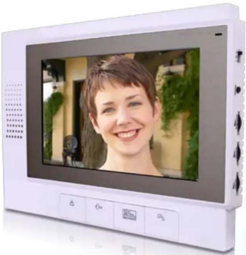
White portable electronic device displaying a smiling woman's face on its screen, with control buttons at the bottom (no visible text or symbols)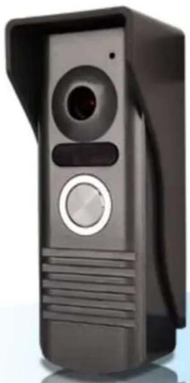
natural_image
Black rectangular electronic device with a circular lens and control panel (no visible text or symbols)Operating Instructions
Before You Begin
FCC Verification:
NOTE: This equipment has been tested and found to comply with the limits for Class B digital device, pursuant to part 15 of the FCC Rules. These limits are designed to provide reasonable protection against harmful interference in a residential installation. This equipment generates, uses and can radiate radio frequency energy and, if not installed and used in accordance with the instructions, may cause harmful interference to radio or television reception, which can be determined by turning the equipment off and on, the user is encouraged to try to correct the interference by one or more of the following measures:
- Reorient or relocate the receiving antenna
- Increase the separation between the equipment and the receiver
- Connect the equipment into an outlet on a circuit different from that to which the receiver is connected
· Consult the dealer or an experienced radio/TV technician for help
IMPORTANT NOTE: Prohibition against eavesdropping
Except for the operations of law enforcement officers conducted under lawful authority, no person shall use, either directly or indirectly, a device operated pursuant to the provisions of this Part for the purpose of overhearing or recording the private conversations of others unless such use is authorized by all of the parties engaging in the conversation.
WARNING: Modifications not approved by the party responsible for compliance could void user's authority to operate the equipment.
IMPORTANT SAFETY INSTRUCTIONS:
· Make sure product is fixed correctly and stable if fastened in place
· Do not operate if wires and terminals are exposed
Table of Contents
Before You Begin 2
Package Contents 3
Overview 4
Layout 5
Installation Guide 6
Connect Wiring 7
Completing Installation 8
Operating the Intercom 9
Troubleshooting 10
Technical Specifications 11
Technical Support / Warranty Information Rear Cover
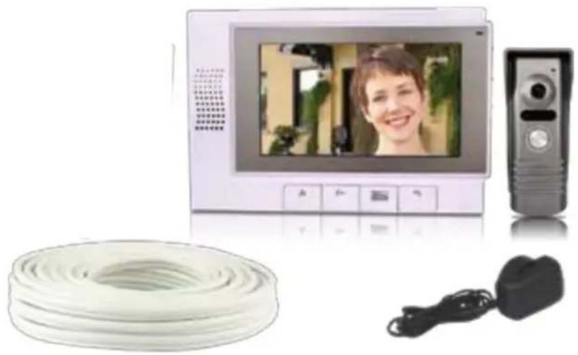
Package Contents
- Indoor LCD Unit
Outdoor Intercom Unit
Indoor LCD Bracket
Outdoor Intercom Bracket
Power Adaptor
50ft (15m) Cable
Mounting Hardware
Operating Instructions
natural_image
Exterior view of a modern office wall-mounted digital camera with a smiling woman on screen, alongside a coiled cable and a portable phone (no visible text or symbols)Overview
Congratulations on your purchase of Swann's high-resolution intercom, the DB-815 which combines a 7" high quality LCD screen with vivid color with a sleek, damage resistant, rust-proof aluminum outdoor intercom unit with a discreet built-in color camera. At night, the camera utilizes its built-in infrared LEDs to provide limited night-vision, so you can see who's there in the dark!
Additionally, the DB-815 can be used to control both an electronic door lock and an electrically operated outdoor gate, giving you the combined benefit of security and convenience.
Like any device which requires permanent installation into your home, installing the DB-815 can be a somewhat complex task which requires an intermediate knowledge of electrical wiring. We strongly suggest that anyone not familiar with electrical wiring not attempt to install the DB-815 themselves – hire a professional.
General Guidelines: Read Before Attempting Installation
Keep the LCD Indoor Unit away from high temperatures, such as near an oven 1. or in direct sunlight, and high humidity, such as bathrooms and greenhouses, as both can easily damage the delicate LCD Unit.
Do not install the LCD Indoor Unit close to a television – the signals the TV and 2. the Intercom use to function can interfere with one another.
Clean the LCD Unit using a soft cloth – there are many specialized LCD cleaning 3. cloths available. Do not use liquids or solvents of any kind.
Do not subject either the indoor or outdoor units to sudden shocks, such as 4. being struck or dropped.
Exercise caution when placing the outdoor unit that the camera will not be 5. exposed to direct sunlight – this will make images very hard to distinguish, and eventually damage the Unit. Remember that the position of the sun varies throughout the day and year.
Most importantly: If you are not experienced with electrical wiring, do not attempt to install the cable through your walls/ceiling yourself - hire a professional!
Layout
Indoor LCD Unit
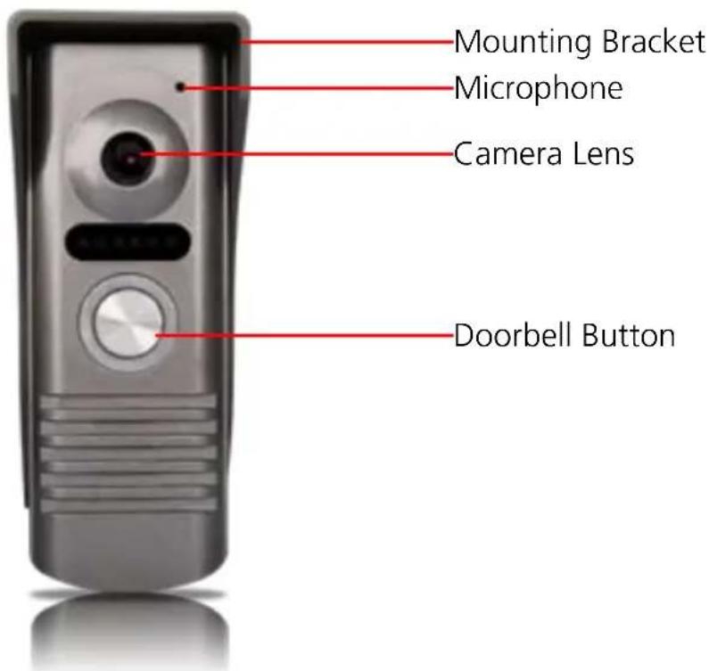
Outdoor Unit
Installation Guide
Installing the DB-815 can be a tricky process, particularly running the cable from the outdoor Unit the indoor LCD Unit. Running cables through walls and/or the ceiling involves drilling holes and then feeding the cable into them. During this procedure, there is always the risk of accidentally making contact with live electrical wiring - the results of which are often lethal.
Thus: if you're not intimately familiar with the electrical wiring in your home, please, hire a professional to install the cable! A small installation fee is certainly preferable to injury or death. However, if you feel confident and able to proceed, or are not installing the cable into the walls/ceiling, the installation procedure is as follows.
Installing the cables:
Run the cable from the location you want the outdoor Unit to the location you • want the indoor unit.
There is no ‘right’ way to do this - one solution (as mentioned above) is to run • the cable through the walls/ceiling. Alternately, you can use a series of cable clips and run the cable on the outside of the walls and through the door frame (if there’s space for it) but this solution is obviously less aesthetically pleasing.
The U-shaped terminals attach to the indoor unit, the bare wires to the outdoor • unit.
Attaching the mounting brackets:
Once the cable is where you want it (leaving enough excess that the wiring can be attached easily), the next step is to attach the mounting brackets to the wall.
Using two screws, mount the outdoor bracket so that the wiring comes • through the lower of the two large openings.
If you're mounting the outdoor bracket onto brickwork, concrete or similar, remember to use proper masonry screws and/or plugs.
Mount the indoor bracket with two screws, so that the wiring protrudes • through the large center hole.
Again, be sure to use screws suitable for the surface. If your walls are plaster • sheeting, make sure the screws enter the framework behind for stability.
flowchart
graph TD
    A["Outdoor unit"] --> B["Indoor unit"]
    B --> C["Lock"]
    B --> D["Outside access"]
    B --> E["Control panel with X1-X5 symbols"]
    style B fill:#f9f,stroke:#333
    style C fill:#ccf,stroke:#333
    style D fill:#cfc,stroke:#333
    style E fill:#fcc,stroke:#333
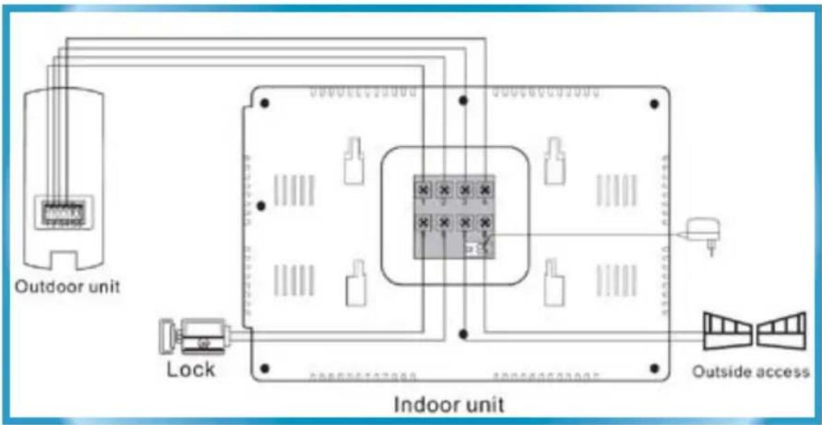
To attach the wiring correctly:
- Attach wires to terminals 1-4 on the rear of the indoor Unit by sliding the U-shaped connection under the screw terminals.
- Screw into place, being careful not to overtighten.
- Attach a control for an electric lock/door-strike to terminals 5 & 6 and controls for an electric gate to terminals 7 & 8 (if applicable).
Attach the bare wire ends into the connections to connections 1-4 on the • outdoor Unit using a small screwdriver or a pen (or similar) to push in the small button atop each wire terminal, and insert the wire.
Release the button and the wire will be clamped firmly in place.
Remember: The small U-shaped connection attaches to the indoor unit, whilst the plain wire end attaches to the outdoor unit.
Suggested wiring solution:
| No. Color Function | ||
| 1 Green Audio | ||
| 2 Black Ground | ||
| 3 Blue Video | ||
| 4 | Brown Power |
Suggested solution only. All four wires in the cable are identical in every respect except their color. Thus, provided terminal 1 on the indoor Unit is connected to 1 on the outdoor Unit, and so forth, the color of the wire used is not particularly important.
Completing Installation
All that's left to do is attach power to the system, and to mount the indoor and outdoor units on the brackets which have already been placed.
To attach power:
Attach the plug on the end of the supplied 12V power supply to the plug on • the rear of the indoor unit.
Plug the power supply into a wall socket. If necessary, turn the wall socket • on.
The system should now have power.
It is not necessary to separately connect power supply to the outdoor unit, as • power is supplied from the connection to the indoor unit.
Attaching the Units to the brackets:
Indoor:
The indoor Unit is simply placed over the mounting bracket so that the top • clasps fit in the holes in the rear of the unit.
Push down to lock the unit in position.
Outdoor:
The outdoor unit should insert into the outdoor unit, clipping into position • when pressed back and up.
To secure it firmly and to prevent tampering, the outdoor unit can be screwed • into position.
To do so, remove the round soft rubber plug on the bottom of the outdoor • unit.
When the unit is in the correct position (ie. inserted fully into the bracket) • insert the supplied smaller screw into this hole and tighten.
Re-apply the rubber plug to prevent unwanted moisture/water entering the • unit.
Using more than one indoor unit:
You can connect a second indoor unit to the Intercom system. You'll need to purchase the second unit in addition to the current kit.
The second unit is wired in parallel with the first: that is, terminal 1 from the outdoor Unit should be wired to terminal 1 on the first monitor which, in turn, is wired to terminal 1 of the second unit. Repeat for connections 2 \~ 4.
Operating the Intercom
Operating the Video Intercom is quite straightforward - doubly so for a visitor - they need only worry about pressing the one button on the outdoor unit!
Here's a rundown of all the buttons on the interior unit and what they do.

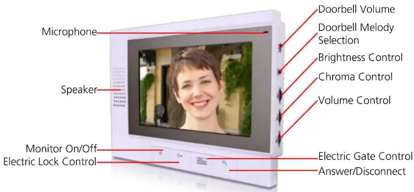
Monitor On/Off: Turns the monitor On or Off. Press once to turn on, and again to turn off. The monitor will turn off automatically if left for approximately 10 seconds without activity. Can be used whether or not the bell has been rung.

Answer/Disconnect: When the doorbell is rung, this button will activate the intercom. Press it again to disconnect. It will automatically disconnect after a short time of inactivity.

Open/Unlock Door: To release an electric door-strike (optional - available separately). Press and hold to keep the door strike open. The door-strike must be connected to the indoor unit as described on page 7.
Open Gate: To open an electric gate (optional). Press once to open the gate - it will close automatically after a set time. The gate control must be connected to the indoor unit as described on page 7.
Melody: Press to cycle through the different tones available for the doorbell. There is no need to confirm - the tone presented when the melody button was pressed most recently is the tone that will be heard when the doorbell is pressed.
Doorbell Volume: How loud the doorbell tone will be. There are three settings, Low, Medium and High.
Volume, Chroma and Brightness Controls:
The volume control determines the loudness of the in-built speaker of the interior unit.
The chroma control determines how much color is in the image - more chroma gives a vibrantly colored image, however too much color can detract from the image quality.
The brightness control determines how light the image appears. At either extreme, the image will seem mostly black or mostly white. Somewhere towards the middle typically achieves the best results.
Troubleshooting
Problem: I hear crackling/hissing or the audio/video is faint or distorted.
Solution: There are two possibilities regarding the cause of this problem.
Firstly, it could indicate that there could be a break or loose connection in the cable connecting the outdoor and indoor units. This is easily checked by removing the outdoor Unit from its bracket, moving it to the indoor Unit and connecting them via a much shorter cable that you know is in good working order.
The second possibility is that something is interfering with the signal. Mains • power cables (the one's between 110V and 240V depending on your location) can generate surprisingly powerful electromagnetic fields. Running your cables to close to these lines can seriously degrade the signal quality.
Problem: The audio/video keeps cutting in and out.
Solution: Don't hold down the video/audio buttons whilst talking. Press the one you want once - the screen/speakers will stay active for some time. Holding the button down can cause them to switch on and off in rapid succession.
Problem: The screen displays only white!
Solution: Try adjusting the brightness control. If this doesn't help, chances are that there is a very bright light source in the cameras field of view, and this is 'washing out' the image. Examples of light sources that can do this include the sun (during the day) or bright street lights (at night). Additionally, if the camera is located in a very shaded area looking into a brightly lit area in the distance (such as being located under an awning, looking at the side of a white house in full sun behind) this extreme contrast can confuse the camera's automatic exposure. Try aiming the camera towards more even lighting.
Problem: The screen displays only black!
Solution: Try adjusting the brightness control. If this doesn't work, check to be sure that there is nothing blocking the lens of the camera - if no light can enter the camera, then there is going to be no image! If the camera is free from obstruction, then the video cable (connection number three, using the blue cable if you've followed our suggested wiring solution) may have been damaged. Finally, remember that the camera has only limited night vision capabilities - if there's nothing within approximately 15ft of the lens (about 4m), then the camera won't see anything in the dark.
DB-815
7" Video Intercom
Video
Image Sensor 1/4" CMOS
Video Quality 380 TV Lines
Viewing Angle 67 degrees
Day/Night Mode Color during day / switches to B&W at night
Night Vision Distance 4m
Display Resolution 1440 x 234
Display Size & Type 7" LCD
General
Operating Power DC12V
Operating Temperature 5^ F \~ 122^ F - 15^ C \~ 50^ C
Dimensions Monitor 9.4" x 6.3" x 0.7"
240mm x 160mm x 17mm
Dimensions Camera 5.1" x 2.0" x 1.9"
130mm x 50mm x 47mm
Weight Monitor 17oz / 500g
Weight Camera 7oz / 200g
Cable Length 50ft / 15m
Helpdesk / Technical Support Details
Swann Technical Support
All Countries E-mail: tech@swannsecurity.com
Telephone Helpdesk
USA toll free
1-800-627-2799
(Su, 2pm-10pm US PT)
(M-Th, 6am-10pm US PT)
(F 6am-2pm US PT)
USA Exchange & Repairs
I-800-627-2799 (Option I)
(M-F, 9am-5pm US PT)
AUSTRALIA toll free
1300 138 324
(M 9am-5pm AUS ET)
(Tu-F I am-5pm AUS ET)
(Sa I am-9am AUS ET)
NEW ZEALAND toll free
0800 479 266
INTERNATIONAL
+61384124610
See http://www.worldtimeserver.com for information on time zones and the current time in Melbourne, Australia compared to your local time.
Warranty Information
Swann Communications USA Inc.
12636 Clark Street
Santa Fe Springs CA 90670
USA
Swann Communications PTY. LTD.
Building 4, 650 Church Street,
Richmond, Victoria 3121
Australia
Swann Communications warrants this product against defects in workmanship and material for a period of one (1) year from it's original purchase date. You must present your receipt as proof of date of purchase for warranty validation. Any Unit which proves defective during the stated period will be repaired without charge for parts or labour or replaced at the sole discretion of Swann. The end user is responsible for all freight charges incurred to send the product to Swann's repair centres. The end user is responsible for all shipping costs incurred when shipping from and to any country other than the country of origin.
The warranty does not cover any incidental, accidental or consequential damages arising from the use of or the inability to use this product. Any costs associated with the fitting or removal of this product by a tradesman or other person or any other costs associated with its use are the responsibility of the end user. This warranty applies to the original purchaser of the product only and is not transferable to any third party. Unauthorized end user or third party modifications to any component or evidence of misuse or abuse of the device will render all warranties void.
By law some countries do not allow limitations on certain exclusions in this warranty. Where applicable by local laws, regulations and legal rights will take precedence.
- High Resolution Intercom with 7" LCD screen
- Operating Instructions
- Before You Begin
- FCC Verification:
- IMPORTANT NOTE: Prohibition against eavesdropping
- IMPORTANT SAFETY INSTRUCTIONS:
- Table of Contents
- Package Contents
- Overview
- General Guidelines: Read Before Attempting Installation
- Layout
- Indoor LCD Unit
- Outdoor Unit
- Installation Guide
- Installing the cables:
- Attaching the mounting brackets:
- To attach the wiring correctly:
- Completing Installation
- To attach power:
- Attaching the Units to the brackets:
- Indoor:
- Outdoor:
- Using more than one indoor unit:
- Operating the Intercom
- Volume, Chroma and Brightness Controls:
- Troubleshooting
- DB-815
- Video
- General
- Helpdesk / Technical Support Details
- Swann Technical Support
- Warranty Information
Brand : SWANN
Model : SW347-DV7
Category : Intercom