
Clarion - Projection screen Draper - Free user manual and instructions
Find the device manual for free Clarion Draper in PDF.


User questions about Clarion Draper
0 question about this device. Answer the ones you know or ask your own.
Ask a new question about this device
Download the instructions for your Projection screen in PDF format for free! Find your manual Clarion - Draper and take your electronic device back in hand. On this page are published all the documents necessary for the use of your device. Clarion by Draper.
USER MANUAL Clarion Draper
Assembly/Mounting Instructions
Clarion Permanently Tensioned Projection Screen by Draper
Caution
① Read instructions through completely before proceeding.
② Follow instructions carefully. Installation con trary to instructions invalidates warranty.
③ When lifting assembled screen, do not lift at only one corner; lift at both corners. Lifting by one corner could result in damage to the screen frame, especially on large screens.
④ Screen should be accessible for complete removal should fabric become damaged or should other ser vice be required.
⑤ Screen should be installed level (using a carpenter's level).
⑥ Nothing should be fastened to screen frame or viewing surface.
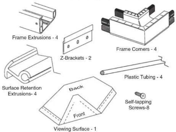
⑦ Make sure you have received all parts (see parts list below and exploded diagram on page 2).
⑧ Screwdriver required for screen assembly; drill and screwdriver needed for attachment to wall.
⑨ The ideal temperature range for assembling folding screens to prevent damaging the surface is 68^-78^ F ( 20^-26^ C). Assembling below recommended temperatures may damage surface and void warranty.
NOTE: Screen has been thoroughly inspected and tested at factory and found to be operating properly prior to shipment.
Clarion—Hardware and Parts List
Frame Preparation
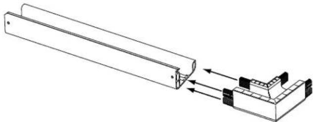
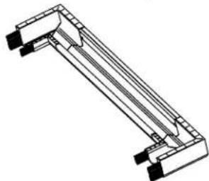
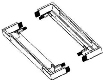
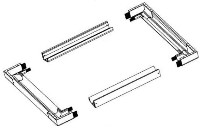
① Clean area and place frame assembly pieces face down. Snap plastic corner pieces into ends of aluminum frame extrusions as indicated in Figures 1 through 4.
natural_image
Technical line drawing of a mechanical assembly with two components and directional arrows indicating movement (no text or symbols)Figure 1
Patented by Draper, Inc., U.S. Patent Nos. 6,785,047; 7,113,332; and 7,369,310.
DRAPER®
411 S. Pearl St., Spiceland, IN 47385 USA ■ 765-987-7999
www.draperinc.com ■ fax 765-987-7142
Copyright © 2011 Draper Inc. Form Clarion_Inst11 Printed in U.S.A.
natural_image
Technical line drawing of a mechanical component with no visible text or symbolsFigure 2
natural_image
Technical line drawing of two mechanical components with mounting brackets (no text or symbols)Figure 3
natural_image
Technical line drawing of four mechanical bracket assemblies (no text or symbols)Figure 4
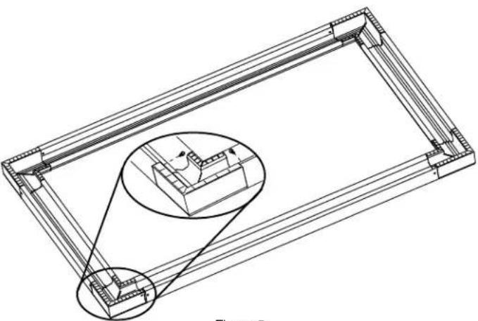
② Check to verify that all four (4) plastic corners are seated securely in aluminum frame extrusion lengths (see Fig. 5). Lock in place using eight (8) self-tapping screws.
Caution: Do not over-tighten fasteners—over-tightening could caUse damage to the frame corners.
natural_image
Technical line drawing of a rectangular frame with internal structural components and an inset magnified detail (no text or symbols)Figure 5
(Continued on Page 2)
If you encounter any difficulties installing or ser vic ing your Clarion screen, call your dealer or Draper, Inc., Spiceland, Indiana, (765) 987-7999; or fax (765) 987-7142.
Clarion by Draper
Surface Preparation
① Move frame assembly out of the way, unroll viewing surface and place on smooth/clean surface. (Orient viewing surface so that folded side of hem is visible.)
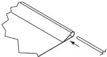
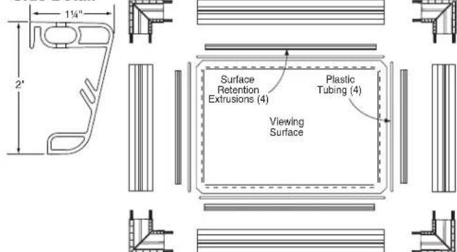
② Insert plastic tubing inside pocket formed by hem on all 4 edges of viewing surface (see Fig. 6).
natural_image
Pure technical line drawing of a mechanical part or bracket without any text, numbers, or symbolsFigure 6
③ Carefully slide surface retention extrusion (rounded edge visible) along hem and onto surface on all four edges of fabric (see Fig. 7).
Caution: Do not allow fabric to snag on the ends of the extrusions. If the screen fabric is not parallel with the surface retention extrusion, then it may slit and tear during installation.
Please Note: To make this step easier, pinch the end of the pocket closed before sliding it into the surface retention extrusion.
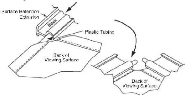
Figure 7
④ Surface retention extrusion should extend beyond edge of viewing surface equally at both ends.
⑤ Verify that all surface retention extrusions are installed with rounded edge visible and are centered on surface material.
Surface to Frame Assembly
① Return frame onto clean surface, face down, and drape completed surface assembly over completed frame profile with rounded edge of surface retention extrusion visible.
② Insert any side of surface to notch #1 on corresponding side of frame extrusion (see Fig. 8).
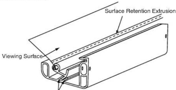
Fabric Attachment Extrusions Figure 8
③ Insert opposite side of surface to notch #1 of frame extrusion.
④ Repeat steps 2-3 with remaining edges of surface.
⑤ Ensure surface retention extrusions are centered lengthwise in tension slots on all 4 edges of surface.
⑥ If additional tension is desired or required over time, adjust surface one edge at a time to tension notch #2.
Please Note: It is not necessary to adjust more than one edge at a time to increase surface tension.
Corner Reinforcement
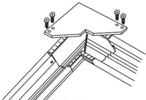
① If screen is being fl own (suspended) or is over 120" (viewing area) height or width, install Corner reinforcement Gussets to all four corners (see Fig. 9).
natural_image
Technical line drawing of a structural joint or bracket assembly (no text or symbols)Figure 9
Mounting Screen to Wall
① Determine height at which screen is to be mounted.
Please Note: Top edge of screen frame will be located 12 " above mounting bracket hole centerline when mounted to wall.
② Mark hole centerline so that both Z-brackets can be mounted parallel and at equal height.
③ Install Z-brackets so that the outermost edges are safely within the overall length of the aluminum frame extrusion to allow for minor horizontal screen adjustments (hardware for mounting Z-brackets to wall is not supplied).
④ Position screen slightly above Z-brackets on wall (see Fig. 10).
Please Note: When lifting screen, do not lift at only one corner; lift at both corners. Lifting by one corner could result in damage to the screen frame, especially on large screens.
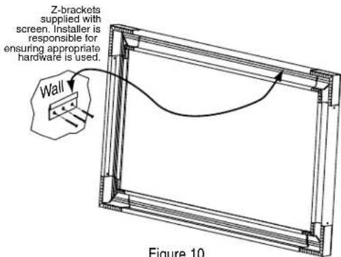
Figure 10
⑤ Lower screen until it engages over Z-brackets. Center screen horizontally on brackets as necessary.
Please Note: Make sure screen is installed level.
*Viewing surface is approximately 14 " from wall.
Clarion Frame— Clarion (Exploded Rear View)
Side Detail*
Please Note: To avoid damage to the frame corners, be sure to support a minimum of two (2) corners when lifting or transporting screen.
Brand : Draper
Model : Clarion
Category : Projection screen