
XLS320 - Loudspeaker MCINTOSH - Free user manual and instructions
Find the device manual for free XLS320 MCINTOSH in PDF.


| Product Type | Two-way bookshelf loudspeaker with Bessel Function Array |
| Brand | McIntosh |
| Model | XLS320 |
| Driver Complement | One 6.5" LD/HP woofer/midrange, five 1" dome tweeters |
| Impedance | 8 ohms nominal |
| Frequency Response (Typical Room) | 50Hz - 34kHz at -6dB |
| Frequency Response (Anechoic) | 80Hz - 34kHz ±2dB |
| Sensitivity | 85dB (2.8V/1m) |
| Crossover Frequency | 1.5kHz |
| Power Handling (Maximum) | 250 Watts |
| Dimensions (H x W x D) | 15-5/16" (38.9cm) x 10-5/8" (27.0cm) x 5-1/4" (13.3cm) |
| Weight (net each) | 24 lbs (10.9kg) |
| Weight (shipping each) | 27 lbs (12.2kg) |
| Enclosure Finish | Textured black powder coated exterior; front, top, bottom in textured black thermal vacuum formed surface |
| Grille Finish | Black knit fabric with Champagne Gold wood trim strips |
| Optional Wood Trims | Natural Cherry, Red Cherry, Black Ash |
| Connectors | Gold-plated binding posts (bi-wire capable) |
| Protection | Automatic resetting solid-state overload protection |
| Mounting Options | On-wall (flush or angled) via supplied brackets; optional in-wall kit |
| Special Features | LD/HP motor structure, Bessel Function tweeter array, mirror image phasing, shielded magnetic field |
| Cleaning | Dry cloth only; do not use liquids |
| Safety | High SPL warning; avoid exposure to rain/moisture; no user-serviceable parts |
Frequently Asked Questions - XLS320 MCINTOSH
User questions about XLS320 MCINTOSH
0 question about this device. Answer the ones you know or ask your own.
Ask a new question about this device
Download the instructions for your Loudspeaker in PDF format for free! Find your manual XLS320 - MCINTOSH and take your electronic device back in hand. On this page are published all the documents necessary for the use of your device. XLS320 by MCINTOSH.
USER MANUAL XLS320 MCINTOSH
Loudspeaker Systems

natural_image
Four black Bilibili speakers displayed on stands, no text or symbols visibleXLS360•XLS340•XLS320•XCS350
Owner's Manual
WARNING - TO REDUCE RISK OF FIRE OR ELECTRICAL SHOCK, DO NOT EXPOSE THIS EQUIPMENT TO RAIN OR MOISTURE.
NO USER-SERVICEABLE PARTS INSIDE. REFER SERVICING TO QUALIFIED PERSONNEL.
To prevent the risk of electric shock, do not remove cover or back. No user serviceable parts inside.
IMPORTANT SAFETY INSTRUCTIONS!
PLEASE READ THEM BEFORE OPERATING THIS EQUIPMENT.
- Read these instructions.
- Keep these instructions.
- Heed all warnings.
- Follow all instructions.
- Do not use this apparatus near water.
- Clean only with a dry cloth.
- Install in accordance with the manufacturer's instructions.
- This apparatus is capable of producing high sound pressure levels. Continued exposure to high sound pressure levels can cause permanent hearing impairment or loss. User caution is advised and ear protection is recommended when playing at high volumes.
- Do not install near any heat sources such as radiators, heat registers, stoves, or other apparatus (including amplifiers) that produce heat.
- Only use attachments/accessories specified by the manufacturer.
- Use only with the cart, stand, tripod, bracket, or
table specified by the manufacturer, or sold with the apparatus. When a cart is used, use caution when moving the cart/apparatus combination to avoid injury from tip-over.

- Refer all servicing to qualified service personnel. Servicing is required when the apparatus has been damaged in any way, liquid has been spilled or objects have fallen into the apparatus, the apparatus has been exposed to rain or moisture, does not operate normally, or has been dropped.
- Do not expose this equipment to dripping or splashing and ensure that no objects filled with liquids, such as vases, are placed on the equipment.
Thank You
Your decision to own a McIntosh Loudspeaker System ranks you at the very top among discriminating music listeners. You now have “The Best.” The McIntosh dedication to “Quality,” is assurance that you will receive many years of musical enjoyment from this unit.
Please take a short time to read the information in this manual. We want you to be as familiar as possible with all the features and functions of your new McIntosh.
Please Take A Moment
The serial number, purchase date and McIntosh Dealer name are important to you for possible insurance claim or future service. The spaces below have been provided for you to record that information:
Serial Number: ____
Purchase Date: ____
Dealer Name:
Technical Assistance
If at any time you have questions about your McIntosh product, contact your McIntosh Dealer who is familiar with your McIntosh equipment and any other brands that may be part of your system. If you or your Dealer wish additional help concerning a suspected problem, you can receive technical assistance for all McIntosh products at:
McIntosh Laboratory, Inc.
2 Chambers Street
Binghamton, New York 13903
Phone: 607-723-1545
Fax: 607-772-3308
Customer Service
If it is determined that your McIntosh product is in need of repair, you can return it to your Dealer. You can also return it to the McIntosh Laboratory Service Department. For assistance on factory repair return procedure, contact the McIntosh Service Department at:
McIntosh Laboratory, Inc.
2 Chambers Street
Binghamton, New York 13903
Phone: 607-723-3515
Fax: 607-723-1917
Copyright 2005, 2006 © by McIntosh Laboratory, Inc.
Table of Contents
Safety Instructions 2
Thank You and Please Take a Moment .... 3
Technical Assistance and Customer Service .... 3
Table of Contents 3
Important Information 4
Introduction 4
Performance Features 5
Dimensions:
XLS320 6
XLS340 7
XLS360 8
XCS350 9
Installation:
Installation Overview 10
Unpacking the XLS320 10
Unpacking the XLS340 10
Unpacking the XLS360 11
Unpacking the XCS350 12
Wall Mounting the XLS320....13
Wall Mounting the XLS340.... 14
Wall Mounting the XCS350 16
Locating the Loudspeaker 18
Tweeter Array Optimization XLS320 19
Tweeter Array Optimization XLS340, XLS360 and XCS350 20
Connections:
Connecting the XLS320 21
Connecting the XLS340, XLS360 and XCS350 (with one amplifier) 22
Connecting the XLS340, XLS360 and XCS350 (with two amplifiers) 23
Specifications:
XLS320 24
XLS340 24
XLS360 25
XCS350 25
Packing Instructions:
XLS320 26
XLS340 26
XLS360 27
XCS350 27
Caution: The XLS360 Loudspeaker weight is 107 pounds (48.5kg) net. It requires two or more persons to handle safely.
- Loudspeaker Cables of adequate size are important to ensure that there will be no significant power loss or heating. Cable size is specified in Gauge numbers or AWG (American Wire Gauge). The smaller the Gauge number, the larger the wire size:
If the Loudspeaker Cables are 25 feet (7.62m) or less, use at least 16 Gauge (AWG) wire size or larger.
If the Loudspeaker Cables are 50 feet (15.24m) or less, use at least 14 Gauge (AWG) wire size or larger.
If the Loudspeaker Cables are 100 feet (30.48m) or less, use at least 12 Gauge (AWG) wire size or larger.
The Loudspeaker Connection Terminals can accept up to 12 Gauge (AWG) wire.
-
For additional connection information, refer to the owner's manual(s) for any component(s) connected to the XLS320, XLS340, XLS360 or XCS350 Loudspeaker.
-
The XLS and XCS Loudspeaker Systems have built-in automatic resetting solid-state devices in the crossover networks for protection. The protection allows a certain amount of overdrive, however extended periods of overdrive will trigger protection. If an obvious lack of high, mid or low frequencies is noticed, the Protection Device may have activated. These devices will automatically reset when the volume level is reduced significantly and kept low until the output of the affected Loudspeaker Element returns to normal.
-
When the XLS340, XLS360 or XCS350 Loudspeaker Systems are driven by more than one amplifier, the output levels of the different amplifiers connected to the Loudspeaker System must be adjusted to achieve a proper balance between the low, midrange/high frequencies reproduced. This adjustment is best achieved through the use of audio test equipment operated by a qualified installer.
Introduction Important Information
The McIntosh XLS320, XLS340, XLS360 and XCS350 Loudspeaker Systems are designed for Home Theater and Music Reproduction. Many of today's Loudspeakers are designed only for Home Theater applications, not so with these Loudspeaker Systems. They are also designed for the accurate reproduction of music.
Motion picture sound effects, explosions, screams, and vehicle crashes require a wide dynamic range and high sound levels. These sounds are such that a speaker system having moderate distortion would reproduce them with little audible difference. This is not true with the reproduction of music. Music is by nature and definition harmonious. To reproduce it accurately, all forms of distortion, both harmonic and intermodulation, must be kept to a minimum. This has been the result of the design of the new McIntosh XLS320, XLS340, XLS360 and XCS350 Loudspeaker Systems. Each loudspeaker element and crossover component has been carefully designed for low distortion, durability and efficiency. The McIntosh XLS320, XLS340, XLS360 and XCS350 Loudspeaker System will reproduce music accurately and function as an excellent Home Theater Loudspeaker.
The XLS320 is a two-way system with a 6-1/2 inch LD/HP ^1 woofer/midrange driver and five 1 inch dome tweeters in a Bessel Function Array. The XLS340 is a three-way system consisting of two 8 inch LD/HP woofers, one 6-1/2 inch LD/HP midrange driver and five 1 inch dome tweeters in a Bessel Function Array. The XLS360 is also a three-way system with two 10 inch LD/HP woofers, one 6-1/2 inch LD/HP midrange driver and five 1 inch dome tweeters in a Bessel Function Array. The XCS350 Center Channel Loudspeaker utilizes two 8 inch LD/HP woofers, one 6-1/2 inch LD/HP midrange driver and five 1 inch dome tweeters in a Bessel Function Array.
The XLS320, XLS340, XLS360 and XCS350 Loudspeaker performance is designed to complement the capabilities of McIntosh's legendary line of Preamplifiers/Control Centers, Signal Sources Devices and Power Amplifiers, without imparting distortion or coloration.
Performance Features
• Patented LD/HP Technology
The McIntosh Low Frequency and Midrange Loudspeaker Elements feature the patented LD/HP motor structure. This design, when compared to conventional Loudspeaker Elements, reduces distortion significantly. It also increases power handling and efficiency.
- Five Tweeter Bessel Function Array
The XLS320, XLS340, XLS360 and XCS350 utilizes five tweeters connected to produce a Bessel Function Array. The individual tweeter amplitudes and phase relationships are adjusted so the array acts as a high frequency point source. One advantage of such an arrangement is a very smooth and even acoustic polar response. This allows the listener to move off axis without suffering a change in high frequency output. The use of multiple tweeters, combined with a mechanical heat sink, also provides greatly increased power handling at high frequencies.
- Mirror Image Phasing High Frequency Array
The five tweeter Bessel Function Array utilizes a unique circuit design permitting the optimization of high frequency dispersion for Mirror Imaging. This allows for Loudspeaker placement in a room as the Left Channel, Center Channel or Right Channel for use in a multi-channel system.
• Shielded Magnetic Field
The XLS320, XLS340, XLS360 and XCS350 may be used in Home Theater Installations near a television receiver or monitor without causing the television image to degrade. McIntosh has designed special shielding around the magnetic structure of the XLS320, XLS340, XLS360 and XCS350 Loudspeaker Elements to prevent interference.
• Special Crossover Network
The Crossover Networks used in the XLS320, XLS340, XLS360 and XCS350 Loudspeaker Systems are designed to ensure an even frequency response over the entire audible range. The Network utilizes First, Second and Third Order design for optimal response.
• High Power Handling
The Loudspeaker Elements and crossover components of the XLS320, XLS340, XLS360 and XCS350 are all chosen for use with powerful amplifiers up to 600 watts.
• High Efficiency
The Loudspeaker Elements used in the XLS320, XLS340, XLS360 and XCS350 Loudspeaker Systems have also been designed for high efficiency. As a result any McIntosh Power Amplifier, even our smallest, will provide satisfying room filling sound.
• Automatic Overload Protection
The XLS320, XLS340, XLS360 and XCS350 have built-in Loudspeaker Element Protection in the form of automatic resetting solid-state devices as a part of the crossover network.
• Gold Plated Input Connectors
The XLS320, XLS340, XLS360 and XCS350 input connectors are gold plated for superior corrosion resistance and high electrical conductivity.
• Rigid Column Structure
The enclosures are an important part of the XLS320, XLS340, XLS360 and XCS350 Loudspeaker Systems. The Systems utilize a dampened rigid enclosure made from extruded aluminum and houses the Loudspeaker Drivers and Crossover. The XLS340 and XLS360 Columns, due to their height, have additional front to back internal bracing to form a dampened rigid Column Structure. The Column's small footprint allows for a variety of different placements in a room.
Dimensions
The following dimensions can assist in determining the best location for the XLS320 or XLS340 Loudspeaker System. There is additional information on page 18 pertaining to installing the Loudspeaker.
Front View of XLS320 with Grille Removed

Rear View of XLS320

Side View of XLS320

Front View of
XLS340 with
Grille Removed

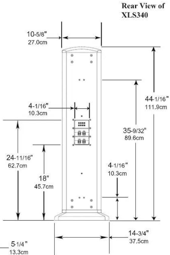
Note: The XLS340 is supplied with optional adjustable feet, four Tiptoes and four Glides. If they are used with the XLS340 please allow for the added height.

Dimensions, con't
The following dimensions can assist in determining the best location for the XLS360 or XCS350 Loudspeaker System. There is additional information on page 18 pertaining to installing the Loudspeaker.
Front View of
XLS360 with
Grille Removed


Note: The XLS360 is supplied with optional adjustable feet, four Tiptoes and four Glides. If they are used with the XLS360 please allow for the added height.

Note: The XCS350 is supplied with an adjustable Stabilizer Bar. Please allow for various height/angle.
Front View of XCS350 with Grille Removed
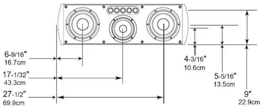
Rear View of XCS350 with the stabilizer bar removed
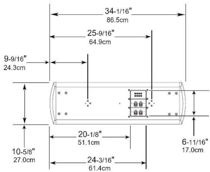
Top View of XCS350

Installation
Installation Overview
The instructions that follow are for the unpacking, assembly and setup of the XLS320, XLS340, XLS360 and XCS350 Loudspeaker Systems as supplied. For several models, an optional In Wall Mounting Kit is available. If the Loudspeaker is to be Mounted On or In Wall, refer to "Locating the Loudspeaker System" on page 18, "Tweeter Array Optimization" on page 19 and "How to Connect" starting on page 20, before beginning the Mounting Process. For additional information on the different types of installation, refer to figure 1.
Caution: The XLS360 Loudspeaker weight is 107 pounds (48.5kg) net and requires two or more persons to safely handle during unpacking, assembly and placement.
It is recommended that the Professionals at your McIntosh Dealer, who are skilled in all aspects of installation and operation, install the Loudspeaker System and any associated audio/video equipment.
Unpacking the XLS320 Loudspeaker
- Remove the entire assembly (Loudspeaker System, Loudspeaker Grille and foam end caps) by lifting up on the bottom of the assembly (Loudspeaker rear) and place it along side the shipping carton on a flat surface.
- Release the Loudspeaker Grille from the foam end caps and remove it from the protective plastic shipping film and set it aside.
- In a similar manner, lift out the Loudspeaker System.
- Close the top flaps of the shipping carton and place the two foam end caps on top of the carton.
- Carefully remove the protective plastic shipping film from the Loudspeaker System so as not to mar the finish or damage the Loudspeaker System Drivers.
Notes: 1. The XLS320 Loudspeaker is supplied with an On Wall Mounting Bracket and Hardware. If the XLS320 is to be mounted on the wall at this time, proceed to "How to Mount the XLS320 Loudspeaker On the Wall" on page 13.
-
When the optional In Wall Mounting Kit is chosen, refer to the supplied installation guide.
-
Place the Loudspeaker System, with the front facing up, on foam end caps located on top of the shipping
carton. Refer to figure 2.
- Orient the Loud- speaker and the Grille with the rounded ends pointing

Figure 2
in the same direction.
- Align the Grille fasteners to the Loudspeaker Grommets (two on each side). Carefully push down to secure the Grille to the Loudspeaker.
- Proceed to "Locating the Loudspeaker System" on page 18.
Unpacking the XLS340 Loudspeaker
- Remove the entire assembly (Loudspeaker System, Loudspeaker Grille and foam end caps) by lifting up on the bottom of the assembly (Loudspeaker rear) and place it along side the shipping carton on a flat surface.
- Release the Loudspeaker Grille from the foam end caps and remove it from the protective plastic shipping film and set it aside.
- In a similar manner, lift out the Loudspeaker System.
- Close the top flaps of the shipping carton and place the two foam end caps on top of the carton.
- Carefully remove the protective plastic shipping film from the Loudspeaker System so as not to mar the finish or damage the Loudspeaker System Drivers.
Notes: 1. When the XLS340 is to be used with the supplied Floor Standing Base and Hardware, proceed to step 6.
2. The XLS340 Loudspeaker is also supplied with On Wall Mounting Brackets and Hardware. If the XLS340 is to be mounted on the wall at this time, proceed to "How to Mount the XLS340 Loudspeakers On the Wall" on page 14.
3. When the optional In Wall Mounting Kit is chosen, refer to the supplied installation guide.
| Installation Methods | ||||
| Loudspeaker Model | Floor Base | Stabilizer Bar | On Wall Mounting Kit | In Wall Mounting Kit |
| XLS320 ---- ---- | Supplied Optional | |||
| XLS340 Supplied ---- Supplied Optional | ||||
| XLS360 Supplied ---- ---- | ---- | |||
| XCS350 ---- | Supplied | Supplied Optional | ||
Figure 1
- Place the Loudspeaker System, with the front facing up, on foam end caps located on top of the shipping carton, with the bottom of the XLS340 overhanging the end of the shipping carton. Refer to figure 3.

Figure 3
-
Using the supplied Allen Wrench, remove four screws from the XLS340 Bottom. Refer to figure 4.
-
Unpack the Floor Standing Base from the other shipping carton.
-
Orient the Floor Standing Base with the widest end of the base facing up and the totally flat side of XLS340. Refer to
-
Attach the Floor Standing Base to the XLS340 using the four supplied machine bolts and washers.
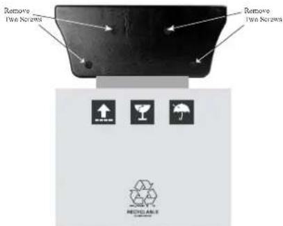
Figure 4

Figure 5
-
Orient the Loudspeaker and the Grille with the rounded ends pointing in the same direction.
-
Align the Grille fasteners to the Loudspeaker Grommets (three on each side). Carefully push down to secure the Grille to the Loudspeaker.
Note: There are four Tiptoes and Glides supplied with the
XLS340. To prevent crushing carpet use the Tiptoe spikes; to protect non-carpeted flooring use the chrome Glides. Both the Glides and Tiptoes have a threaded shaft and locking nut that screw into the tapped holes in the bottom of the Floor Standing Base. The feet can be in- adjusted to compensate for uneven
Tiptoes
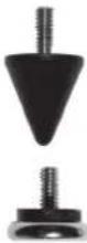
- Proceed to "Locating the Loudspeaker System" on page 18.
Unpacking the XLS360 Loudspeaker
-
Remove the entire assembly (Loudspeaker System, Loudspeaker Grille and foam center/end caps) by lifting up on the bottom of the assembly (Loudspeaker rear) and place it along side the shipping carton on a flat surface.
-
Release the Loudspeaker Grille from the foam center/end caps and remove it from the protective plastic shipping film and set it aside.
-
In a similar manner, lift out the Loudspeaker System.
-
Replace the shipping carton top onto the shipping carton bottom. Place one foam end cap and one foam center cap on top of the carton. Refer to figure 6 on the next page.
-
Carefully remove the protective plastic shipping film from the Loudspeaker System so as not to mar the finish or damage the Loudspeaker System Drivers.
Note: The XLS360 is a sealed Acoustic System. If it is to be used without the supplied Floor Standing Base attached to the bottom, the four unused holes on the bottom of the loudspeaker need to be plugged up with suitable material to prevent air leaks. Proceed to step 10 if the Floor Standing Base is not used.
-
Place the Loudspeaker System, with the front facing up, on foam end caps located on top of the shipping carton, with the bottom of the XLS360 overhanging the end of the shipping carton. Refer to figure 6 on the next page.
-
Unpack the Floor Standing Base from the other shipping carton.
Installation, con't

Figure 6
- Orient the Floor Standing Base with the widest end of the base facing up and the totally flat side of the base pointing away from the XLS360. Refer to figure 7.

Figure 7
- Attach the Floor Standing Base to the XLS360 using the four supplied machine bolts and washers.
- Orient the Loudspeaker and the Grille with the rounded ends pointing in the same direction.
- Align the Grille fasteners to the Loudspeaker Grommets (four on each side). Carefully push down to secure the Grille to the Loudspeaker.
Note: There are four Tiptoes and Glides supplied with the
XLS360. To prevent crushing carpet use the Tiptoe spikes; to protect non-carpeted flooring use the chrome Glides. Both the Glides and Tiptoes have a threaded shaft and locking nut that screw into the tapped holes in the bottom of the Floor Standing Base. The feet can be

independently adjusted to compensate for uneven flooring.
- Proceed to "Locating the Loudspeaker System" on page 18.
Unpacking the XCS350 Loudspeaker
- Remove the entire assembly (Loudspeaker System, Loudspeaker Grille and foam end caps) by lifting up on the bottom of the assembly (Loudspeaker rear) and place it along side the shipping carton on a flat surface.
- Release the Loudspeaker Grille from the foam end caps and remove it from the protective plastic shipping film and set it aside.
- In a similar manner, lift out the Loudspeaker System.
- Close the top flaps of the shipping carton and place the two foam end caps on top of the carton.
- Carefully remove the protective plastic shipping film from the Loudspeaker System so as not to mar the
finish or damage the Loudspeaker System Drivers.
Notes: 1. When the XCS350 is to be used with the supplied Stabilizer Bar and Hardware, proceed to step 6.
2. The XCS350 Loudspeaker is also supplied with On Wall Mounting Brackets and Hardware. If the XCS350 is to be mounted on the wall at this time, proceed to "How to Mount the XCS350 Loudspeakers On the Wall" on page 16.
3. When the optional In Wall Mounting Kit is chosen, refer to the supplied installation guide.
- Place the Loudspeaker System, with the front facing down, on foam end caps located on top of the shipping carton. Refer to figure 8.
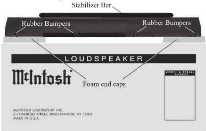
Figure 8
-
Attach the four rubber bumpers to the bottom long edge of the XCS350 Loudspeaker System. Refer to figure 8.
-
Loosen, but do not remove, the three screws securing the Stabilizer Bar to the back of the XCS350. Refer to figure 9.
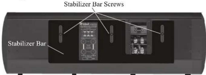
Figure 9
- Reposition the Stabilizer Bar even with the previously applied rubber bumpers on the side edge of the XCS350 enclosure. Refer to figure 10.

Figure 10
-
Tighten the three screws securing the Stabilizer Bar to keep it in place, but not enough to prevent changing the angle of the XCS350 in the following steps.
-
The vertical angle of the XCS350 may be changed ±5.5 degrees from perpendicular, allowing the sound to be directed upwards or downwards to accommodate the seating arrangement in the room. Refer to figure 11.
This can be accomplished by temporarily loosening the three screws and moving the Stabilizer Bar up or down. When the desired angle is achieved, tighten the three screws.

natural_image
Three identical black flag-like shapes on white background, no text or symbols presentFigure 11
- Rotate the XCS350 Loudspeaker over with the front facing up, being careful not to damage the Loudspeaker Drivers. Refer to figure 12.


Figure 12
-
Locate the Loudspeaker Grille and align the Grille fasteners to the Loudspeaker Grommets (four on each side). Carefully push down to secure the Grille to the Loudspeaker.
-
Proceed to "Locating the Loudspeaker System" on page 18.
How to Mount the XLS320 Loudspeaker On the Wall
The supplied On Wall Mounting Brackets allow for two different mounting positions of the XLS320 Loudspeaker relative to the wall. The first position is flush mount, with the Loudspeaker close to and parallel with the wall. The second position is angle mount, which places the Loudspeaker further away from the wall and allows for horizontal rotation of ± 30 Degrees. Refer to figure 13.

Figure 13
- Using the supplied Allen Wrench, remove two screws from the rear of the XLS320 Loudspeaker System located below the recessed connection plate. Refer to figure 14 on the next page.
Installation, con't
- Attach either the flush mount or angle mount bracket to the rear of the Loudspeaker using the two screws (just removed in the previous step), being sure to orient the bracket as illustrated in figures 15 and 16.
- Determine the Loudspeaker Mounting Location on the wall, making sure the Mounting Bracket will be anchored to a stud located inside the wall.
Note: Use
extreme caution to avoid any existing electricawiring, plumbing located in the wall.

natural_image
Close-up of a black door handle with a metallic lever, no visible text or symbolsFigure 15
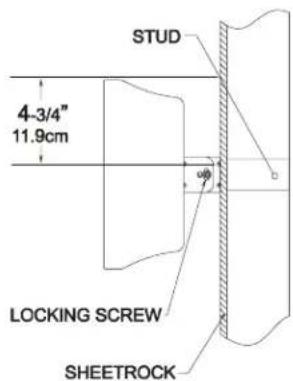
- Refer to figures 17 and 18 to install the appropriate Wall Bracket on the wall (orient the bracket as illustrated) using the supplied Mounting Screws. If the Flush Mount Bracket is used,

Figure 14

natural_image
Close-up of a metal door handle with a lever mechanism (no text or symbols visible)Figure 16
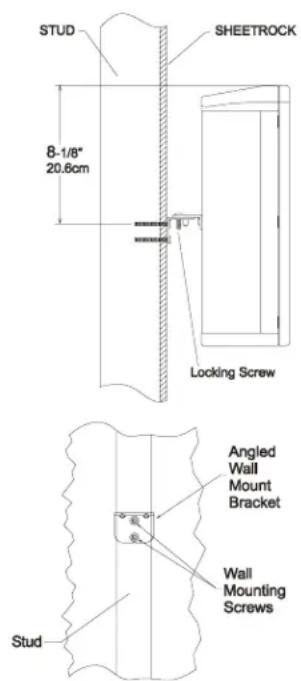
Figure 17

Figure 18
attach the two cone shaped rubber bumpers to the rear of the Loudspeaker, near the bottom.
Note: If the wall covering material and/or thickness is different from the illustration, the two supplied Mounting Screws need to be replaced with screws of the appropriate type and length.
- Orient the Loudspeaker with the rounded end at the Top, carefully line up the Loudspeaker Bracket with the Wall Bracket and lower the Loudspeaker. If the angle mount is used, install the Locking Screw to secure the Loudspeaker at the desired angle.
- Align the Grille fasteners to the Loudspeaker Grommets (two on each side). Carefully push down to secure the Grille to the Loudspeaker.
How to Mount the XLS340 Loudspeaker On the Wall
The supplied On Wall Mounting Brackets allow for two different mounting positions of the XLS340 Loudspeaker relative to the wall. The first position is flush mount, with the Loudspeaker close to and parallel with the wall. The second position is angle mount, which places the Loudspeaker further away from the wall and allows for horizontal rotation of ± 30 Degrees. Refer to figure 19.
- Using the supplied Allen Wrench, remove four screws
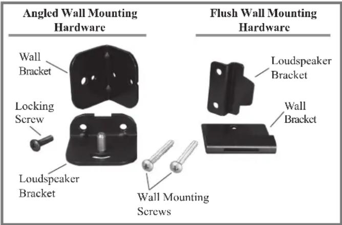
Figure 19
from the rear of the XLS340 Loudspeaker System. Refer to figure 20.
- Attach either the flush mount or angle mount brackets to the rear of the Loudspeaker using the four screws (just removed in the previous step), being sure to orient the bracket as illustrated in figures 21 and 22.
- Determine the Loudspeaker Mounting Location on the wall, making sure the Mounting Brackets will be anchored to a stud located inside the wall.
Note: Use extreme caution to avoid any existing electrical wiring, plumbing, etc., located inside the wall.
- Refer to figures 23 and 24 to install the appropriate Wall Brackets on the wall (orient the bracket as illustrated) using the supplied Mounting Screws. If the Flush Mount Brackets are used, optionally attach the two cone shaped rubber bumpers to the rear of the Loudspeaker, near the bottom.
Note: If the wall covering material and/or thickness is different from the illustration, the two supplied Mounting Screws need to be replaced with screws of the appropriate type and length.
-
Orient the Loudspeaker with the rounded end at the Top, carefully line up the Loudspeaker Brackets with the Wall Brackets and lower the Loudspeaker. If the angle mount is used, install the Locking Screw for the top Bracket to secure the Loud-speaker at the desired angle.
-
Align the Grille fasteners to the Loudspeaker Grommets (three on each side). Carefully push down to secure the Grille
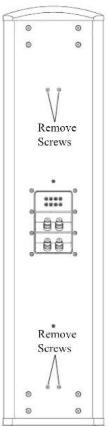
Figure 20

natural_image
Close-up of a metallic bracket with a cylindrical pin and mounting bracket (no text or symbols visible)Figure 21

natural_image
Close-up of a mechanical clamp or bracket mounted on a wall (no visible text or symbols)Figure 22
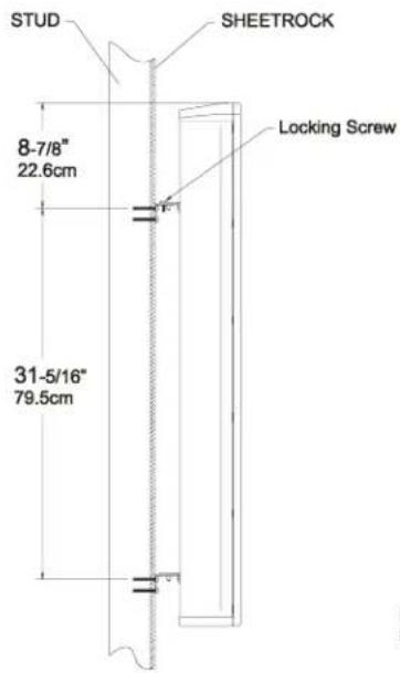


Figure 23 Figure 24
Installation, con't
to the Loudspeaker.
How to Mount the XCS350 Loudspeaker On the Wall The supplied On Wall Mounting Brackets allow for four different mounting positions of the XCS350 Loudspeaker relative to the wall, both vertical and horizontal. Two positions are flush mount, with the Loudspeaker close to and parallel with the wall. The other positions are angle mount, which
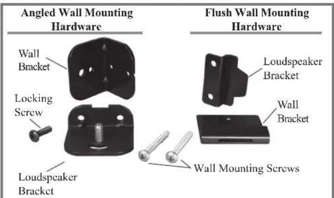
Figure 25
places the Loudspeaker further away from the wall and allows for rotation of ± 30 Degrees. Refer to figure 25.
- Using the supplied Allen Wrench, remove the three screws securing the Stabilizer Bar to the back of the XCS350. Refer to figure 26. Replace the just removed center screw with a supplied one of the same type, but
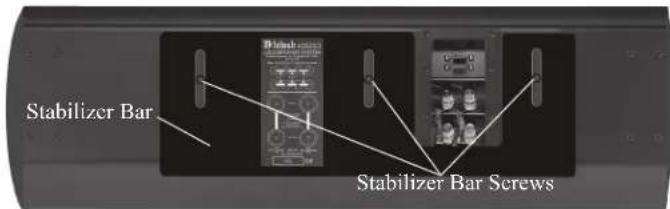
Figure 26
shorter length. Refer to figure 28.
Note: Retain the three removed screws and Stabilizer Bar for possible future use.
- Attach either the flush mount or angle mount brackets to the rear of the Loudspeaker using the supplied screws. Refer to figures 27, 28 and 29 for the screw
| XCS350 Screw Removal for Mounting | ||
| Mounting Type Screws - | A Screws - B | |
| Vertical Flush Mount ---- | Remove | |
| Vertical Angle Mount ---- | Remove | |
| Horizontal Flush Mount R | Remove ---- | |
| Horizontal Angle Mount --- | Remove | |
Figure 27

flowchart
graph TD
    A["Location of Mounting Screws"] --> B["Replace with supplied shorter screw"]
    B --> C["Location of Mounting Screws"]
Figure 28
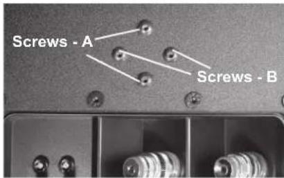
Figure 29
location. Also, be sure to orient the bracket as illustrated in figure 30.
- Determine the Loudspeaker Mounting Location on the wall, making sure the Mounting Bracket will be anchored to a stud located inside the wall.
Note: Use extreme caution to avoid any existing electrical wiring, plumbing, etc., located inside the wall.
- Refer to figures 31 thru 34 to install the appropriate Wall Bracket on the wall (orient the bracket as illustrated) using the supplied Mounting Screws. If the Flush Mount Bracket is used, attach the two cone shaped rubber
bumpers to the rear of the Loudspeaker, near the bottom.
Note: If the wall covering material and/or thickness is different from the illustration, the two supplied Mounting Screws need to be replaced with screws of the appropriate type and length.
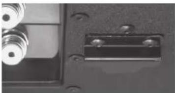
- Orient the Loudspeaker to line up with the Wall Brackets and attach them
natural_image
Close-up of a mechanical component with metallic pins and mounting holes (no visible text or symbols)Figure 30

natural_image
Close-up of a black door handle with metal bracket and scroll (no text or symbols visible)
natural_image
Close-up of a mechanical component with bolts and a clip, no visible text or symbolstogether. If the angle mount is used, install the Locking Screw to secure the Loudspeaker at the desired angle. 6. Align the Grille fasteners to the Loudspeaker Grommets (four on each side). Carefully push down to secure the Grille to the Loudspeaker.


Figure 33

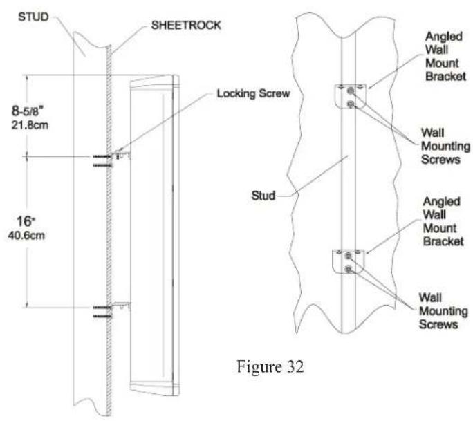
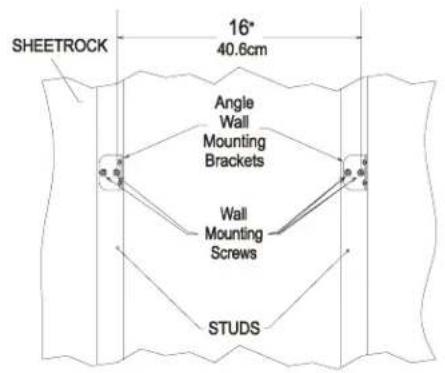
Figure 34
Installation, con't
Locating the Loudspeaker System for the XLS320
Loudspeaker placement in a room can greatly affect performance. The XLS320, XLS340, XLS360 and XCS350 are designed for use as a Left and Right Loudspeaker in a Music System, or as a Front and Surround Loudspeakers in a Home Theater System.
The optimal method for selecting speaker locations includes the use of a real time spectrum analyzer operated by the Professionals at your McIntosh Dealer. An uncompromising installation would take into consideration the floor, wall and ceiling coverings, the type and placement of furniture and can even include the architectural design of the room and its construction materials.
Locating Loudspeakers for use in Home Theater
In a Home Theater application, the placement of Front Loudspeakers can be limited by such considerations as the size and location of the video monitor. The locating suggestions in the “for use in a Music System” section below can still be helpful. Side Surround Loudspeakers work best located to either side of and above the listening position, the same distance from the monitor. Back Surround Loudspeakers work best on the back wall. Refer to figure 35.
Locating Loudspeakers for use in a Music System
When used in a Music System, the distance between the loudspeakers should not exceed the distance between the listener and either loudspeaker for the best sound imaging. Refer to figure 36. The Loudspeaker System's Tweeter Array should be inline with the listeners' ears. Placement near a wall, corner, floor, ceiling or any intersecting surfaces will reinforce some bass frequencies. Which bass frequencies are boosted by placement in a particular location is dependent on the dimensions of the room. Test the various loudspeaker locations by playing music with continuous bass, setting up the speakers and listening to them from the main listening spot. Move the loudspeakers to an alternate location and repeat the listening, paying attention to how articulate the bass notes are. Experiment with various loudspeaker positions until the locations that sound best are found.

Tweeter Array Optimization
The XLS320 Loudspeaker System incorporates a special feature in the Crossover Network for optimization of the sound coming from the five tweeter array, refer to figure 37A. The three different settings in the crossover network
have to do with the physical location of the Loudspeaker in the Home Theater and/or Music System.

natural_image
Close-up of a dark, oval-shaped object with five circular indentations arranged horizontally (no text or symbols visible)Figure 37A
On the rear panel of the Loudspeaker System, there is a recessed connection plate with binding posts for connection
of hookup cables. Adjacent to the binding posts on the same recessed connection plate, are two rows of jacks with two McIntosh Jumpers already inserted, refer to figure 38A. The default position of the jumpers for the XLS320 Loudspeaker System is C, refer to figure 39A.
For the best sound performance, it is important to make sure the jumpers are set according to the Loudspeaker System loca-
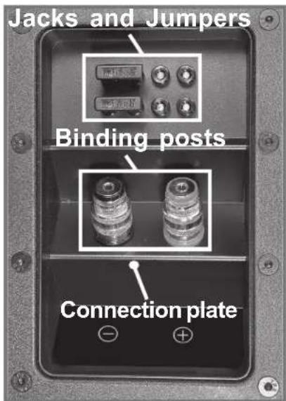
Figure 38A
tion in the room. Refer to the chart below for the correct Jumper positions; if necessary, remove the two jumpers and reinsert them for the Loudspeaker location.
| XLS320 Crossover Jumper Settings | |||
| Loudspeaker Location A B C | |||
| Left Front ---- ---- | Jumpers | ||
| Center Front ---- | Jumpers | ---- | |
| Right Front | Jumpers | ---- ---- | |
| Left Surround ---- ---- | Jumpers | ||
| Right Surround | Jumpers | ---- ---- | |
| Left Back Surround | Jumpers | ---- ---- | |
| Right Back Surround ---- | ---- | Jumpers | |

Figure 39A
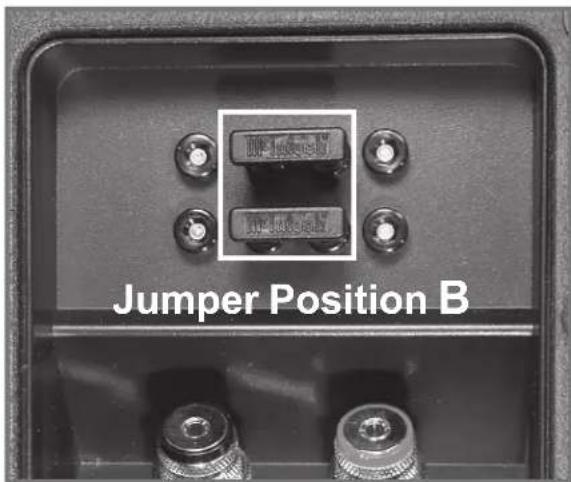
Figure 40A

Figure 41A
Tweeter Array Optimization for the XLS340, XLS360 and XCS350
The XLS340, XLS360 and XCS350 Loudspeaker Systems incorporate a special feature in the Crossover Network for optimization of the sound coming from the five tweeter
array, refer to figure 37B. The three different settings in the crossover network have to do with the

natural_image
Five circular button-like objects arranged horizontally (no text or symbols visible)Figure 37B
physical location of the Loudspeaker in the Home Theater and/or Music System.
On the rear panel of the Loudspeaker System there is a recessed connection plate with binding posts for connection of hookup cables. Adjacent to the binding posts on the same recessed connection plate, are two rows of jacks with two McIntosh Jumpers already inserted, refer to figure 38B. The default position of the jumpers for the XLS340 and XLS360 Loudspeaker Systems is RIGHT,
refer to figure 39B. The XCS350's default position of the jumpers is CENTER, refer to figure 40B.
For the best sound performance, it is important to make sure the jumpers are set according to the Loudspeaker System location in the room. Refer to the chart below for the correct Jumper positions; if necessary, remove the two jumpers and reinsert them for the Loudspeaker location.
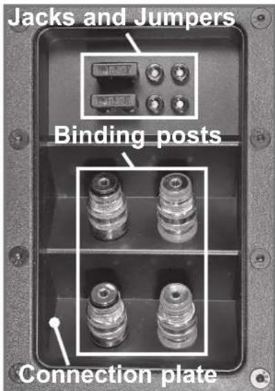
Figure 38B
| XLS340/360 and XCS350 Crossover Jumper Settings | |||
| Loudspeaker Location | Left Center R | ght | |
| Left Front Jumpers ---- | --- | ||
| Center Front ---- Jumpers | ---- | ||
| Right Front ---- Jumpers | |||
| Left Surround Jumpers ---- | ---- | ||
| Right Surround ---- Jumpers | |||
| Left Back Surround | ---- ---- | Jumpers | |
| Right Back Surround | Jumpers ---- | ---- | |

Figure 39B
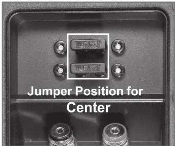
Figure 40B

Figure 41B
How to Connect the XLS320 Loudspeakers
Preparing Hookup Cables
The McIntosh Loudspeaker Systems utilize binding posts for speaker wire connections. Prepare the Loudspeaker Hookup Cables that attach to the Power Amplifier Output Terminals:
Bare wire cable ends:
Carefully remove sufficient insulation from the cable ends, refer to figures 43, 44 and 45. If the cable is
stranded, carefully twist the strands together as tightly as possible.

Note: If desired, the twisted ends can be tinned with solder to keep the strands together and/or attach a spade lug.
Spade lug or prepared wire connection:
Insert the spade lug connector or prepared section of the cable end into the terminal side access hole, and
tighten the terminal cap until the cable is firmly clamped
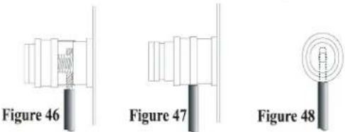
into the terminal so the wires cannot slip out. Refer to figures 46, 47 and 48.
Connections using a single Amplifier
- Connect a Loudspeaker cable from the COMmon (Negative) Binding Post of the appropriate Amplifier Channel to the Loudspeaker NEGATIVE (-) Binding Post.
- Connect a Loudspeaker cable from the 8Ω (OHM) or Positive (+) Binding Post of the same Amplifier Channel to the Loudspeaker POSITIVE (+) Binding Post.
- Tighten all of the Loudspeaker and Amplifier Binding Posts.
- Connect the remaining Loudspeaker(s) and Amplifier Channel(s) in the same manner.

Connection with one Amplifier
Preparing Hookup Cables
The McIntosh Loudspeaker Systems utilize binding posts for speaker wire connections. Prepare the Loudspeaker Hookup Cables that attach to the Power Amplifier Output Terminals:
Bare wire cable ends:
Carefully remove sufficient insulation from the cable
ends, refer to
figures 43, 44
and 45. If the
cable is
stranded, carefully twist the
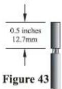
Figure 44

Figure 45

strands together as tightly as possible.
Note: If desired, the twisted ends can be tinned with solder to keep the strands together and/or attach a spade lug.
Spade lug or prepared wire connection:
Insert the spade lug connector or prepared section of the cable end into the terminal side access hole, and
tighten the
terminal
cap until the cable is firmly clamped

into the terminal so the wires cannot slip out. Refer to figures 46, 47 and 48.
Connections using a single Amplifier
- Connect a Loudspeaker cable from the COMmon (Negative) Binding Post of the appropriate Amplifier Channel to the Loudspeaker NEGATIVE (-) Binding Post.
- Connect a Loudspeaker cable from the 8Ω (OHM) or Positive (+) Binding Post of the same Amplifier Channel to the Loudspeaker POSITIVE (+) Binding Post.
Note: The WOOFER and MID/TWT NEGATIVE (-) Binding
Posts must have a jumper installed between them. Likewise, the WOOFER and MID/TWT POSITIVE (+) Binding Posts must also have a jumper installed between them.
- Tighten all of the Loudspeaker and Amplifier Binding Posts.
- Connect the remaining Loudspeaker(s) and Amplifier Channel(s) in the same manner.
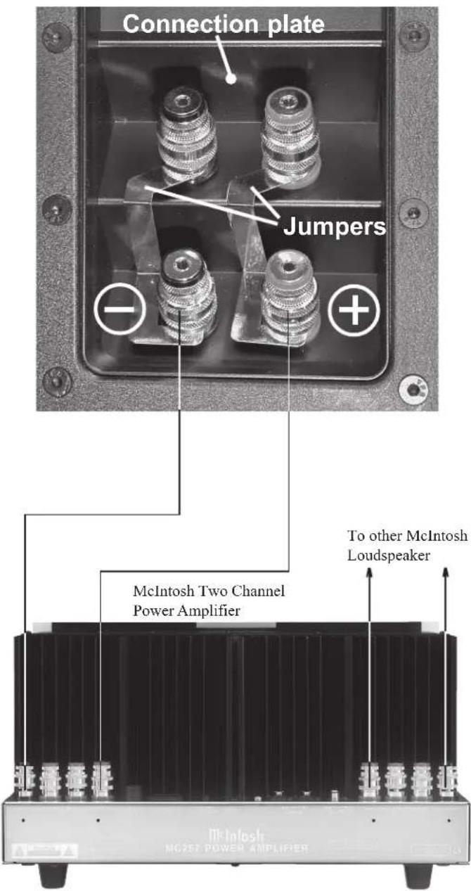
Connection with two Amplifiers
Preparing Hookup Cables
The McIntosh Loudspeaker Systems utilize binding posts for speaker wire connections. Prepare the Loudspeaker Hookup Cables that attach to the Power Amplifier Output Terminals:
Bare wire cable ends:
Carefully remove sufficient insulation from the cable
ends, refer to figures 43, 44 and 45. If the cable is stranded, care fully twist the

Figure 44

Figure 45

strands together as tightly as possible.
Note: If desired, the twisted ends can be tinned with solder to keep the strands together and/or attach a spade lug.
Spade lug or prepared wire connection:
Insert the spade lug connector or prepared section of the cable end into the terminal side access hole, and
tighten the terminal cap until the cable is firmly clamped

into the terminal so the wires cannot slip out. Refer to figures 46, 47 and 48.
Connections using two Amplifiers
- Remove both Jumpers between WOOFER and MID/TWT Binding Posts.
- Connect a Loudspeaker cable from the COMmon (Negative) Binding Post of the appropriate Channel of Amplifier Number One to the Loudspeaker WOOFER
NEGATIVE (-) Binding Post.
- Connect a Loudspeaker cable from the 8Ω (OHM) or Positive (+) Binding Post of the same Channel of Amplifier Number One to the Loudspeaker WOOFER POSITIVE (+) Binding Post.
- Connect a Loudspeaker cable from the COMmon (Negative) Binding Post of the appropriate Channel of Amplifier Number Two to the Loudspeaker MID/TWT NEGATIVE (-) Binding Post.
- Connect a Loudspeaker cable from the 8Ω (OHM) or Positive (+) Binding Post of the same Channel of Amplifier Number Two to the Loudspeaker MID/TWT POSITIVE (+) Binding Post.
- Tighten all of the Loudspeaker and Amplifier Binding Posts.
- Connect the remaining Loudspeaker(s) and Amplifier Channel(s) in the same manner.


natural_image
Close-up of a mechanical component with two threaded pins and a plus sign, no visible text or symbols
XLS320 Specifications
Driver Complement
One 6-1/2 inch LD/HP Woofers/Midrange
Five 1 inch Dome Tweeters (in a Bessel Function Array)
Impedance
8 ohms Nominal
Frequency Response
50Hz - 34kHz -6dB (Typical Room)
80Hz - 34kHz ± 2dB (Anechoic Response)
Sensitivity
85dB (2.8V/1m)
Crossover Frequency
1.5kHz
Power Handling
250 Watts Maximum
Overall Dimensions
15-5/16 inches (38.9cm) Height
10-5/8 inches (27.0cm) Width
5-1/4 inches (13.3cm) Depth
Enclosure Finish
The outside of the enclosure is finished with a textured black powder coated finish; the front, top and bottom of the enclosure is covered with a thermal vacuum formed durable surface in a textured black finish.
Grille Finish
Black knit fabric with wood trim strips finished in
Champagne Gold
Optional Wood Trim Finishes
Natural Cherry, Red Cherry or Black Ash
(Check with your McIntosh Dealer for Additional Details)
Weight (each)
24 pounds (10.9kg) net, 27 pounds (12.2kg) in shipping carton
XLS340 Specifications
Driver Complement
Two 8 inch LD/HP Woofers
One 6-1/2 inch LD/HP Midrange
Five 1 inch Dome Tweeters (in a Bessel Function Array)
Impedance
8 ohms Nominal
Frequency Response
38Hz - 34kHz -6dB (Typical Room)
65Hz - 34kHz ± 2dB (Anechoic Response)
Sensitivity
85dB (2.8V/1m)
Crossover Frequencies
1.5kHz
250Hz
Power Handling
400 Watts Maximum
Overall Dimensions (including Floor Standing Base)
44-1/16 inches (111.9cm) Height
14-3/4 inches (37.5cm) Width
12 inches (30.5cm) Depth
Enclosure Finish
The outside of the enclosure is finished with a textured black powder coated finish; the front, top and bottom of the enclosure is covered with a thermal vacuum formed durable surface in a textured black finish. The base is also covered with a thermal vacuum formed durable surface in a textured black finish
Grille Finish
Black knit fabric with wood trim strips finished in Champagne Gold
Optional Wood Trim Finishes
Natural Cherry, Red Cherry or Black Ash
(Check with your McIntosh Dealer for Additional Details)
Weight (each)
69 pounds (31.3kg) net, 76 pounds (34.5kg) in shipping carton
XLS360 Specifications
Driver Complement
Two 10 inch LD/HP Woofers
One 6-1/2 inch LD/HP Midrange
Five 1 inch Dome Tweeters (in a Bessel Function Array)
Impedance
8 ohms Nominal
Frequency Response
34Hz - 34kHz -6dB (Typical Room)
55Hz - 34kHz ± 2dB (Anechoic Response)
Sensitivity
85dB (2.8V/1m)
Crossover Frequencies
1.5kHz
250Hz
Power Handling
600 Watts Maximum
Overall Dimensions (including Floor Standing Base)
51-3/8 inches (130.5cm) Height
17-3/4 inches (45.1cm) Width
13 inches (33.0cm) Depth
Enclosure Finish
The outside of the enclosure is finished with a textured black powder coated finish; the front, top and bottom of the enclosure is covered with a thermal vacuum formed durable surface in a textured black finish. The base is also covered with a thermal vacuum formed durable surface in a textured black finish
Grille Finish
Black knit fabric with wood trim strips finished in Champagne Gold
Optional Wood Trim Finishes
Natural Cherry, Red Cherry or Black Ash
(Check with your McIntosh Dealer for Additional Details)
Weight (each)
107 pounds (48.5kg) net, 120 pounds (54.4kg) in shipping carton
XCS350 Specifications
Driver Complement
Two 8 inch LD/HP Woofers
One 6-1/2 inch LD/HP Midrange
Five 1 inch Dome Tweeters (in a Bessel Function Array)
Impedance
8 ohms Nominal
Frequency Response
45Hz - 34kHz -6dB (Typical Room)
80Hz - 34kHz ± 2dB (Anechoic Response)
Sensitivity
85dB (2.8V/1m)
Crossover Frequencies
1.5kHz
250Hz
Power Handling
400 Watts Maximum
Overall Dimensions (including Stablizer Bar)
10-5/8 inches (27cm) Height
34-1/16 inches (86.5cm) Width
6 inches (15.3cm) Depth
Enclosure Finish
The outside of the enclosure is finished with a textured black powder coated finish; the front and side ends of the enclosure are covered with a thermal vacuum formed durable surface in a textured black finish.
Grille Finish
Black knit fabric with wood trim strips finished in
Champagne Gold
Optional Wood Trim Finishes
Natural Cherry, Red Cherry or Black Ash
(Check with your McIntosh Dealer for Additional Details)
Weight (each)
49 pounds (22.2kg) net, 55 pounds (24.9kg) in shipping carton
Packing Instructions
In the event it is necessary to repack the equipment for shipment, the equipment must be packed exactly as shown below. The XLS360 shipping carton uses banding straps to make sure the box is held together securely.
Note: The Floor Stand must be removed from the XLS340/XLS360 Loudspeaker and packed in its own shipping carton.
Use the original shipping carton and parts only if they are in good serviceable condition. If a shipping carton or any of the interior part(s) are needed, please call or write Customer Service Department of McIntosh Laboratory. Please see the Parts List for the correct part numbers.
XLS320 Shipping Carton and Parts List

Quantity Part Number Description
1 034293 Shipping carton
2 034291 Foam end caps
XLS340 Shipping Cartons and Parts List

natural_image
Technical line drawing of a multi-level industrial machine assembly (no text or symbols visible)Quantity Part Number Description
1 034292 Shipping carton
2 034291 Foam end caps
1 034207 Floor stand shipping carton
1 033300 Microfoam to wrap up the floor stand
1 033085 Air Cap bottom pad

natural_image
Isometric diagram of a layered geometric structure with no text or symbolsXLS360 Shipping Cartons and Parts List
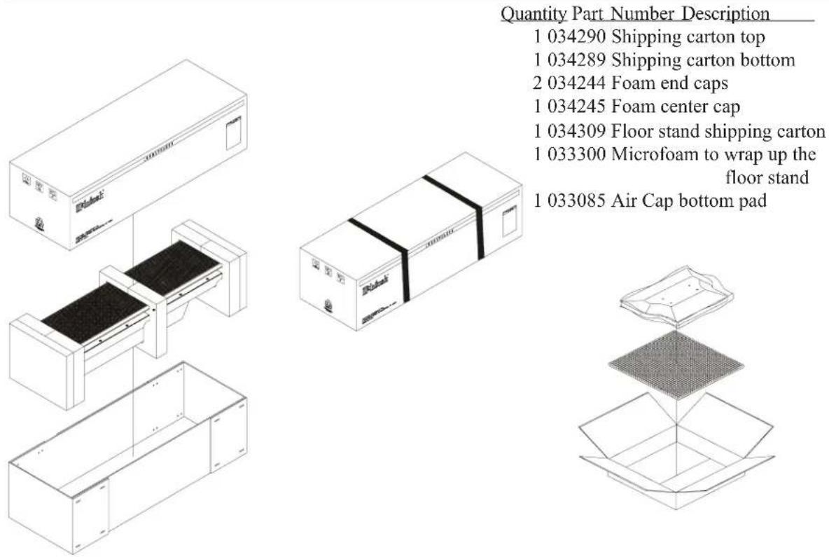
Quantity Part Number Description
1 034290 Shipping carton top
1 034289 Shipping carton bottom
2 034244 Foam end caps
1 034245 Foam center cap
1 034309 Floor stand shipping carton
1 033300 Microfoam to wrap up the floor stand
1 033085 Air Cap bottom pad
XCS350 Shipping Carton and Parts List

natural_image
Technical line drawing of a solar panel assembly with labeled components (no text or symbols present)
McIntosh Laboratory, Inc.
2 Chambers Street
Binghamton, NY 13903
The continuous improvement of its products is the policy of McIntosh Laboratory Incorporated who reserve the right to improve design without notice.
Printed in the U.S.A.


- WARNING - TO REDUCE RISK OF FIRE OR ELECTRICAL SHOCK, DO NOT EXPOSE THIS EQUIPMENT TO RAIN OR MOISTURE.
- NO USER-SERVICEABLE PARTS INSIDE. REFER SERVICING TO QUALIFIED PERSONNEL.
- IMPORTANT SAFETY INSTRUCTIONS!
- PLEASE READ THEM BEFORE OPERATING THIS EQUIPMENT.
- Thank You
- Please Take A Moment
- Technical Assistance
- Customer Service
- Table of Contents
- Dimensions:
- Installation:
- Connections:
- Specifications:
- Packing Instructions:
- Caution: The XLS360 Loudspeaker weight is 107 pounds (48.5kg) net. It requires two or more persons to handle safely.
- Introduction Important Information
- Performance Features
- • Patented LD/HP Technology
- - Five Tweeter Bessel Function Array
- - Mirror Image Phasing High Frequency Array
- • Shielded Magnetic Field
- • Special Crossover Network
- • High Power Handling
- • High Efficiency
- • Automatic Overload Protection
- • Gold Plated Input Connectors
- • Rigid Column Structure
- Dimensions
- Dimensions, con't
- Installation
- Installation Overview
- Unpacking the XLS320 Loudspeaker
- Unpacking the XLS340 Loudspeaker
- Unpacking the XLS360 Loudspeaker
- Installation, con't
- Unpacking the XCS350 Loudspeaker
- How to Mount the XLS320 Loudspeaker On the Wall
- How to Mount the XLS340 Loudspeaker On the Wall
- Locating the Loudspeaker System for the XLS320
- Locating Loudspeakers for use in Home Theater
- Locating Loudspeakers for use in a Music System
- Tweeter Array Optimization
- Tweeter Array Optimization for the XLS340, XLS360 and XCS350
- How to Connect the XLS320 Loudspeakers
- Preparing Hookup Cables
- Connections using a single Amplifier
- Connection with one Amplifier
- Connection with two Amplifiers
- Connections using two Amplifiers
- XLS320 Specifications
- Driver Complement
- Impedance
- Frequency Response
- Sensitivity
- Crossover Frequency
- Power Handling
- Overall Dimensions
- Enclosure Finish
- Grille Finish
- Optional Wood Trim Finishes
- Weight (each)
- XLS340 Specifications
- Crossover Frequencies
- Overall Dimensions (including Floor Standing Base)
- XLS360 Specifications
- XCS350 Specifications
- Overall Dimensions (including Stablizer Bar)
- Packing Instructions
- XLS320 Shipping Carton and Parts List
- XLS340 Shipping Cartons and Parts List
- XLS360 Shipping Cartons and Parts List
- Quantity Part Number Description
- XCS350 Shipping Carton and Parts List
Brand : MCINTOSH
Model : XLS320
Category : Loudspeaker