
AX411 - Access Point Juniper - Free user manual and instructions
Find the device manual for free AX411 Juniper in PDF.


| Product Type | Wireless Access Point |
| Brand | Juniper Networks |
| Model | AX411 |
| Wireless Standards | IEEE 802.11a/b/g/n |
| Radio Support | Dual radio (2.4 GHz and 5 GHz) |
| Maximum Data Rate | Up to 300 Mbps per radio (802.11n) |
| Virtual Access Points (VAPs) | Up to 16 per radio (32 total) |
| Ethernet Ports | 1 x Gigabit Ethernet (10/100/1000) |
| Console Port | 1 x RJ-45 console |
| Power Source | PoE (802.3af) or external 12V DC power supply |
| Management | Centrally managed by Juniper SRX Series Services Gateways |
| Authentication | Local MAC filtering, RADIUS-based MAC, 802.1X, WPA-Enterprise, firewall authentication |
| Security Features | WPA/WPA2, VLAN segregation, HTTP redirect captive portal, RADIUS VLAN assignment |
| Quality of Service (QoS) | 802.11e WMM support |
| Deployment Modes | Layer 2 (bridged) and Layer 3 (routed) management |
| Regulatory Compliance | FCC, ETSI, TELEC, and other country-specific certifications |
| Dimensions (Approx.) | 17.5 x 13.5 x 3.5 cm (6.9 x 5.3 x 1.4 in) |
| Weight (Approx.) | 0.5 kg (1.1 lb) |
| Operating Temperature | 0°C to 40°C (32°F to 104°F) |
| Humidity | 10% to 90% non-condensing |
| Firmware Upgrade | Via SRX Series gateway using CLI or J-Web |
Frequently Asked Questions - AX411 Juniper
User questions about AX411 Juniper
0 question about this device. Answer the ones you know or ask your own.
Ask a new question about this device
Download the instructions for your Access Point in PDF format for free! Find your manual AX411 - Juniper and take your electronic device back in hand. On this page are published all the documents necessary for the use of your device. AX411 by Juniper.
USER MANUAL AX411 Juniper
CONFIGURING AND DEPLOYING THE AX411 WIRELESS ACCESS POINT
Table of Contents
Introduction....3
Scope 3
Design Considerations....3
Hardware Requirements....3
Software Requirements 3
Description and Deployment Scenario....3
AX411 Features ....3
Operational Model 4
L2 Management Mode 4
L3 Management Mode 5
Configuration 5
RADIUS Support 7
Description and Deployment Scenarios ....7
L2 Management Mode....7
L3 Management Mode....9
Segregating User and Management Traffic....11
MAC Authentication....12
RADIUS-Based MAC Authentication....13
Creating Multiple Wireless Networks Using VAPs....14
Creating a Guest Network Using Firewall Authentication....17
RADIUS-Based VLAN Assignment....19
Administration and Monitoring 21
Monitoring....21
Firmware Upgrade 23
Summary 23
Appendix: AX411 Wireless LAN Access Point Certification Listing 23
Part Numbers Affected 23
About Juniper Networks.... 25
Table of Figures
Figure 1: L2 management mode....4
Figure 2: L3 management mode....5
Figure 3: L2 management mode example....7
Figure 4: L3 management mode example....9
Figure 5: Segregating user and management traffic 11
Figure 6: RADIUS-based MAC authentication....13
Figure 7: Using multiple VAPs....14
Figure 8: Firewall authentication....17
Figure 9: RADIUS-based VLAN assignment 20
List of Tables
Table 1: AX411 Feature Summary ....3
Table 2: L2 vs. L3 Forwarding Mode....5
Table 3: Supported RADIUS Attributes ....7
Introduction
Juniper Networks ^a has introduced a wireless access point solution that is integrated into Juniper Networks SRX Series Service Gateways. This new product line allows for a simple deployment of Wi-Fi networks in the branch while leveraging the advanced capabilities of Juniper's services gateways for AP Management. SRX Series for the branch includes the ability to provide advanced security services like unified threat management (UTM), intrusion prevention system (IPS), firewalling, unified access control, and VPNs.
Scope
The purpose of this application note is to provide an overview of the different deployment scenarios for Juniper's Wi-Fi solution for the branch. This application note begins by detailing the capabilities of the Juniper Networks AX411 Wireless Access Point and how it is configured. The final sections of this application note provide some typical deployment scenarios and their configurations.
Design Considerations
SRX Series Services Gateways are used to monitor and configure the AX411 access points. These devices support Power over Ethernet (PoE) and can be powered by SRX Series gateways that support PoE. Alternatively, an external power supply is provided with each access point that can be used when PoE is not available.
Hardware Requirements
- Juniper Networks SRX Series for the branch (SRX100 line and SRX200 line of services gateways, and the SRX650 Services Gateway)
Software Requirements
- Juniper Networks Junos ^18 operating system release 10.0 or later
Description and Deployment Scenario
AX411 Features
The AX411 access point provides support for a wide range of features and protocols targeted for small to medium sized deployments in branch offices. For larger deployments of more than 4 access points, or where location services are desired, the Juniper Networks WLA and WLC Product line are recommended. The following table summarizes some of the most important characteristics of this product.
Table 1: AX411 Feature Summary
| FEATURE DETAILS | |
| Dual radio support Yes | |
| PHY protocols supported 802.11a, 802.11b, 802.11g, and 802.11n | |
| 802.11h spectrum and transmit power management extensions Yes | |
| 802.11d specification for operation in additional regulatory domains Yes | |
| 802.11e quality of service enhancements Yes | |
| Number of virtual access points supported Up to 16 per radio (32 total) | |
| Gigabit Ethernet ports 1 | |
| Console port 1 | |
| 802.1q support Yes | |
| Authentication | Local and RADIUS |
| MAC authentication | Yes |
| HTTP redirect support | Yes |
| Access point clustering support | Yes, in Junos OS 10.1 and later. |
Operational Model
The AX411 access points are managed from branch SRX Series Services Gateways, allowing for a simpler, centralized provisioning model. In particular, the following operations can be performed directly from the SRX Series gateways.
- Configuration management: The entire configuration for all AX411s are performed within JunOS at the branch gateway and pushed to the access points using a secure connection to the AX411 device. The Junos OS infrastructure is used to provide configuration backup and restore, auditing, scripting, role-based authentication, etc.
- Monitoring: Access points are monitored from the services gateway, including the ability to obtain device and wireless network information from the command-line interface (CLI), J-Web Software, or SNMP.
- Device maintenance: Device maintenance support includes firmware upgrades.
When an access point is connected to a branch gateway for the first time, it requests an IP address using the Dynamic Host Configuration Protocol (DHCP). After obtaining an IP address, a registration protocol is used to exchange configuration and status information between the devices.
The SRX Series gateway uses the media access control (MAC) address received in the registration messages to identify each access point. The advantage of using this approach is that access points can be connected to any port or given any IP address while still being correctly identified since MAC addresses are fixed.
Internet Control Message Protocol (ICMP) is used as a "keepalive" protocol between each access point and the SRX Series gateway. If an access point detects a failure, it automatically stops broadcasting any service set identifier (SSID) that it has configured, thus allowing the client stations to associate to a different access point and circumvent the failure.
Access points can be managed in two different modes.
• Layer 2 management mode
- Layer 3 management mode
L2 Management Mode
The default and most common mode is to connect all access points to the same L2 network. A single routed VLAN interface (RVI) is configured per VLAN, which is used as the default gateway for the VLAN. This RVI is then added to a security zone. Access point to access point traffic can be forwarded at L2. The gateway can do so at line rate, without the need to inspect such traffic. Traffic from wireless nodes connected to the access point will be inspected by the SRX security gateway. In this configuration the SRX acts as a DHCP server for the VLAN, and both APs and wireless endpoints obtain their IP address from this DHCP scope.

flowchart
graph TD
    A["Client"] --> B["SRX Series"]
    B --> C["DHCP Handles out addresses in the 192.168.1.0/24"]
    B --> D["Internet"]
    B --> E["OFFICE"]
    style A fill:#f9f,stroke:#333
    style B fill:#ccf,stroke:#333
    style C fill:#cfc,stroke:#333
    style D fill:#fcc,stroke:#333
    style E fill:#cff,stroke:#333
Ports
All access point facing ports are connected to interfaces in switching mode and associated to the default vlan
Figure 1: L2 management mode
L3 Management Mode
In this mode, each access point is connected to a different subnet on the branch services gateway. Traffic between access points is routed and inspected by the branch device.

flowchart
graph TD
    A["Client"] --> B["SRX Series"]
    B --> C["Internet"]
    subgraph DHCP
        D["192.168.1.0/24"] --> E["192.168.3.1/24"]
        F["192.168.2.0/24"] --> G["192.168.2.1/24"]
        H["192.168.3.0/24"] --> I["192.168.3.0/24"]
    end
    B --> J["ge-0/0/3.0"]
    B --> K["ge-0/0/2.0"]
    B --> L["ge-0/0/1.0"]
Ports
All access point facing ports are connected to interfaces in switching mode and associated to the default vlan
Figure 2: L3 management mode
Analogous to these, customer traffic can be forwarded using either one of these modes on a per access point basis, i.e., any given access point can be connected to the gateway either in L2 or L3 mode. With this in mind, it is important to understand the different tradeoffs between these modes.
Table 2: L2 vs. L3 Forwarding Mode
| FEATURE L2 MODE L3 MODE | ||
| Access point to access point communication (and client to client communication when clients are in different access points) | Done in hardware at line rate but without any security inspection. | Firewall and UTM services are available, but at the expense of forwarding performance. |
| Firewall authentication Not supported for L2 switched traffic. Yes | ||
| Client to client isolation Not always possible (proxy-arp can be used to force all client to client traffic to be sent to the gateway, where security policies can be enforced). | Yes | |
| QoS Not supported for client to client traffic. Yes | ||
| Configuration complexity Simpler configuration, since a single L3 interface is shared between all access points. | Complex, as each access point is connected to a different L3 interface, with each requiring the configuration of an IP address, a DHCP server, security zones, and policies. | |
| Roaming Client roaming is supported, if MAC authentication or no authorization protocol is used. If authentication is used, clients will have to log in every time they associate to a new access point. | Roaming will require clients to send a new DHCP request in order to obtain a new IP address. | |
Configuration
The configuration is found under [wlan] hierarchy. In Junos OS release 10.0, each access point has to be configured individually. Junos OS 10.1 includes the ability to group access points into clusters, where all access points share the same configuration. Access points in a cluster exchange both configuration and operational information and do not require operators to make changes to each individual access point. The clustering feature will be discussed in a future version of this document.
wlan {
    access-point <AP name> {
    mac-address <ap mac address>;
    #This attribute is mandatory and can be found on relabel of AX411
    description <AP description>;
    location <AP location>;
    external {
    system {
    console baudrate <console baudrate>;
    ports {
    ethernet {
    management-vlan <vlan-id>;
    untagged-vlan <vlan-id>;
    static {
    address <Access Point address>;
    gateway <default gateway>;
    }
    }
    }
    }
    dot1x-supplicant {
    username <username>;
    password <password>;
    }
}
access-point options {
country <country where the AP is located>;
#This is used for regulatory purposes.
#The AP will only transmit in the bands allowed by each country

station-mac-filter {
#Allow and deny list of mac addresses, used for local mac authentication
}
radio <1|2> {
quality-of-service {
#QoS configuration options
}
radio-options {
#Phy layer configuration options, such as transmit power, channel, mode, etc
}
virtual-access-point <0..15> {
#virtual-access-point configuration options including SSID, security
#and http redirect options
}
}
The configuration is divided into three sections—the external, radio, and options sections.
The external section is used to specify the basic access point parameters used to manage the device, including its address (when DHCP is not used), VLAN ID used for management traffic, and native VLAN ID (i.e., VLAN ID used for untagged traffic).
In order to comply with the different regulatory domains, each access point must be configured with the name of the country where it is being deployed. This is done under the access point options, and it is used to determine the range of channels and maximum transmit power allowed in that domain.
Finally, all radio, client authentication, and SSID options are configured under the radio section. The following deployment scenarios will show some typical configurations, and they will be used to introduce some of the configuration options available.
RADIUS Support
One or more (for redundancy purposes) RADIUS servers can be used to authenticate users. When a user is granted access, the RADIUS protocol provides a mechanism to pass user-specific parameters to the access point. These parameters allow passing per-user configuration options, centrally managed by the RADIUS server.
The following table displays the list of RADIUS attributes that can be passed to the AX411 access point, as specified in RFC 3580.
Table 3: Supported RADIUS Attributes
| ATTRIBUTE NAME VALUE TYPE DEFINED IN | |||
| Session-Timeout 27 integer RFC2865 | |||
| Tunnel-Type 64 integer RFC2868 | |||
| Tunnel-Medium-Type 65 integer RFC2868 | |||
| Tunnel-Private-Group-ID 81 integer RFC2868 | |||
| WISPR-Max-Bandwidth-Down 7 | integer VSA (14122) | ||
| WISPR-Max-Bandwidth-Up | 8 | integer VSA (14122) | |
Description and Deployment Scenarios
We will start by configuring basic access point management access for both L2 and L3 modes. These configurations will be used as the starting point in subsequent scenarios.
L2 Management Mode
In this mode, all access points are connected to the SRX Series for the branch by means of an Ethernet switched network, either using an external switch or the ports on the SRX Series gateway configured for switching. A single L3 interface is used to provide connectivity to all of the access points. This interface also serves as the default gateway for the wireless clients.
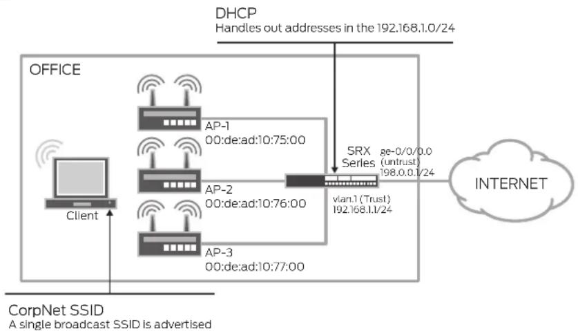
flowchart
graph TD
    A["OFFICE"] -->|DHCP Handles out addresses in the 192.168.1.0/24| B["SRX Server"]
    B --> C["Internet"]
    D["Client"] --> E["AP-1 AP-2 AP-3"]
    E --> F["00:de:ad:10:75:00"]
    E --> G["00:de:ad:10:76:00"]
    E --> H["00:de:ad:10:77:00"]
    I["CorpNet SSID A single broadcast SSID is advertised"] --> J["AP-1 AP-2 AP-3"]
    J --> K["vlan.1 (Trust) 192.168.1.1/24"]
    K --> L["SRX Server"]
    L --> M["ge-0/0/0.0 (untrust) 198.0.0.1/24"]
Figure 3: L2 management mode example
For completeness, security policies, Network Address Translation (NAT), and untrust interface configurations required to allow traffic from the access points to the Internet are included in this configuration. To avoid unnecessary repetitions and unless explicitly noted, our next examples will omit these sections from the configuration.
Enable PoE if you will be using that to power the AX411.
set poe interface all
#DHCP Server config
set system services dhcp name-server 4.2.2.2 set system services dhcp pool 192.168.2.0/24 address-range low 192.168.2.2 set system services dhcp pool 192.168.2.0/24 address-range high 192.168.2.254 set system services dhcp pool 192.168.2.0/24 router 192.168.2.1
#Interface and VLAN Configuration
Note how interface-ranges can be used to simplify the configuration when a large number of APs are used
set interfaces interface-range APs member ge-0/0/1 set interfaces interface-range APs member fe-0/0/2 set interfaces interface-range APs member fe-0/0/3 set interfaces interface-range APs unit 0 family ethernet-switching vlan members default set interfaces ge-0/0/0 unit 0 family inet address 198.0.0.1/24
Untrust Static IP
set interfaces vlan unit 2 family inet address 192.168.2.1/24 set vlans default vlan-id 2 set vlans default l3-interface vlan.2
Routing is trivial, there is only a default route pointing to the Internet set routing-options static route 0.0.0.0/0 next-hop 10.0.1.1
NAT all traffic from the WifiNet to untrust. Use the IP address of the egress interface as the new source.
set security nat source rule-set Internet-Access from zone WiFiNet set security nat source rule-set Internet-Access to zone untrust set security nat source rule-set Internet-Access rule nat-all match source-address 0.0.0.0/0 set security nat source rule-set Internet-Access rule nat-all then source-nainterface
Security Zones and policies configuration. Please note that the vlan.0 interface MUST be assigned to a zone
set security zones security-zone untrust interfaces ge-0/0/0.0
It is important to allow both DHCP and PING otherwise the SRX will not discover the APs
set security zones security-zone WifiNet interfaces vlan.2 host-inbound-traffic system-services dhcp set security zones security-zone WifiNet interfaces vlan.2 host-inbound-traffic system-services ping set security policies from-zone WifiNet to-zone untrust policy allow-internet-access match source-address any set security policies from-zone WifiNet to-zone untrust policy allow-internet-access match destination-address any set security policies from-zone WifiNet to-zone untrust policy allow-internet-access match application any set security policies from-zone WifiNet to-zone untrust policy allow-internet-access then permit
APs configuration. By default all traffic not assigned to a VLAN is send untagged.
Both radios are used (radio 1 in the 5hz band and radio 2 in the 2.4Ghzs band) and broadcast the same SSID
#AP-1
set wlan access-point AP-1 mac-address 00:12:cf:c5:4a:40
set wlan access-point AP-1 access-point-options country US
set wlan access-point AP-1 radio 1 virtual-access-point 0 ssid WifiNet
set wlan access-point AP-1 radio 1 virtual-access-point 0 security none
set wlan access-point AP-1 radio 2 virtual-access-point 0 ssid WifiNet
set wlan access-point AP-1 radio 2 virtual-access-point 0 security none
#AP-2
set wlan access-point AP-2 mac-address 00:12:cf:c5:4b:40
set wlan access-point AP-2 access-point-options country US
set wlan access-point AP-2 radio 1 virtual-access-point 0 ssid WifiNet
set wlan access-point AP-2 radio 1 virtual-access-point 0 security none
set wlan access-point AP-2 radio 2 virtual-access-point 0 ssid WifiNet
#AP-3
set wlan access-point AP-3 mac-address 00:12:cf:c5:4c:40
set wlan access-point AP-3 access-point-options country US
set wlan access-point AP-3 radio 1 virtual-access-point 0 ssid WifiNet
set wlan access-point AP-3 radio 1 virtual-access-point 0 security none
set wlan access-point AP-3 radio 2 virtual-access-point 0 ssid WifiNet
The AX411 access points use the concept of a Virtual Access Point (VAP). A VAP appears to the wireless client as a single independent access point, advertising a single service set identifier (SSID). In our first configuration, only a single SSID is advertised and this signifies that a single VAP on each radio is being used.
L3 Management Mode
In this mode, each access point is connected to a different L3 interface. Since each interface belongs to a different subnet, clients will get their addresses assigned from a pool based on the access point to which they are associated.

flowchart
graph TD
    A["Client"] --> B["AP-1"]
    A --> C["AP-2"]
    A --> D["AP-3"]
    B --> E["ge-0/0/0.0 (trust)"]
    C --> F["ge-0/0/0.0 (trust)"]
    D --> G["ge-0/0/0.0 (trust)"]
    E --> H["SRX Series"]
    F --> H
    G --> H
    H --> I["Internet"]
    J["DHCP Each Interface Handles Out Addresses from a different pool"] --> K["Client"]
    style J fill:#f9f,stroke:#333
    style K fill:#ccf,stroke:#333
CorpNet SSID
A single broadcast SSID is advertised
Figure 4: L3 management mode example
Enable PoE if you will be using that to power the AX411.
set poe interface all
DHCP Server config. A different pool per (AP) interface is used
set system services dhcp name-server 4.2.2.2 set system services dhcp pool 192.168.1.0/24 address-range low 192.168.1.2 set system services dhcp pool 192.168.1.0/24 address-range high 192.168.1.254 set system services dhcp pool 192.168.1.0/24 router 192.168.1.1 set system services dhcp pool 192.168.2.0/24 address-range low 192.168.2.2 set system services dhcp pool 192.168.2.0/24 address-range high 192.168.2.254 set system services dhcp pool 192.168.2.0/24 router 192.168.2.1 set system services dhcp pool 192.168.3.0/24 address-range low 192.168.3.2 set system services dhcp pool 192.168.3.0/24 address-range high 192.168.3.254 set system services dhcp pool 192.168.3.0/24 router 192.168.3.1
Interface configurations
set interfaces ge-0/0/1 unit 0 family inet address 192.168.1.1/24 set interfaces ge-0/0/2 unit 0 family inet address 192.168.2.1/24 set interfaces ge-0/0/3 unit 0 family inet address 192.168.3.1/24
Security Zones and policies configuration.
An intra-zone policy is added to allow traffic between clients connected to different APs
set security zones security-zone untrust interfaces ge-0/0/0.0 set security zones security-zone WifiNet interfaces ge-0/0/1.0 set security zones security-zone WifiNet interfaces ge-0/0/1.0 host-inbound-traffic system-services dhcp set security zones security-zone WifiNet interfaces fe-0/0/2.0 set security zones security-zone WifiNet interfaces fe-0/0/2.0 host-inbound-traffic system-services dhcp set security zones security-zone WifiNet interfaces fe-0/0/3.0 set security zones security-zone WifiNet interfaces fe-0/0/3.0 host-inbound-traffic system-services dhcp
set security policies from-zone WifiNet to-zone WifiNet policy permit-egress-traffic match source-address any set security policies from-zone WifiNet to-zone WifiNet policy permit-egress-traffic match destination-address any set security policies from-zone WifiNet to-zone WifiNet policy permit-egress-traffic match application any set security policies from-zone WifiNet to-zone WifiNet policy permit-egress-traffic then permit set security policies from-zone WifiNet to-zone untrust policy allow-internet-access match source-address any set security policies from-zone WifiNet to-zone untrust policy allow-internet-access match destination-address any set security policies from-zone WifiNet to-zone untrust policy allow-internet-access match application any set security policies from-zone WifiNet to-zone untrust policy allow-internet-access then permit
APs configuration. The APs config is identical to the one in our previous example
set wlan access-point AP-1 mac-address 00:12:cf:c5:4a:40 set wlan access-point AP-1 access-point-options country US set wlan access-point AP-1 radio 1 virtual-access-point 0 ssid WifiNet set wlan access-point AP-1 radio 1 virtual-access-point 0 security none set wlan access-point AP-1 radio 2 virtual-access-point 0 ssid WifiNet set wlan access-point AP-1 radio 2 virtual-access-point 0 security none
AP-2
set wlan access-point AP-2 mac-address 00:12:cf:c5:4b:40
set wlan access-point AP-2 access-point-options country US
set wlan access-point AP-2 radio 1 virtual-access-point 0 ssid WifiNet
set wlan access-point AP-2 radio 1 virtual-access-point 0 security none
set wlan access-point AP-2 radio 2 virtual-access-point 0 ssid WifiNet
#AP-3
set wlan access-point AP-3 mac-address 00:12:cf:c5:4c:40
set wlan access-point AP-3 access-point-options country US
set wlan access-point AP-3 radio 1 virtual-access-point 0 ssid WifiNet
set wlan access-point AP-3 radio 1 virtual-access-point 0 security none
set wlan access-point AP-3 radio 2 virtual-access-point 0 ssid WifiNet
Segregating User and Management Traffic
In this example, VLAN tags are used to separate management traffic from user traffic. This configuration can be applied to both L2 and L3 deployment modes. From this example on, only the L2 mode will be shown (as it is the most popular method) but it should be apparent from our previous example how to configure each scenario in L3 mode.

flowchart
graph LR
    Client -->|Wireless Signal| Server1["AP-1 00:de:ad:10:75:00"]
    Client -->|Wireless Signal| Server2["AP-2 00:de:ad:10:76:00"]
    Client -->|Wireless Signal| Server3["AP-3 00:de:ad:10:77:00"]
    Server1 --> SRX_Series["SRX Series"]
    Server2 --> SRX_Series
    Server3 --> SRX_Series
    SRX_Series --> Internet["INTERNET"]
    style Internet fill:#f9f,stroke:#333
CorpNet SSID
A single broadcast SSID is advertised
Figure 5: Segregating user and management traffic
#DHCP Server config
set system services dhcp pool name-server 4.2.2.2
#This pool is used by the management vlan
set system services dhcp pool 192.168.1.0/24 address-range low 192.168.1.2
set system services dhcp pool 192.168.1.0/24 address-range high 192.168.1.254
set system services dhcp pool 192.168.1.0/24 router 192.168.1.1
#This pool is used by the WifiNet vlan
set system services dhcp pool 192.168.2.0/24 address-range low 192.168.2.2
set system services dhcp pool 192.168.2.0/24 address-range high 192.168.2.254
set system services dhcp pool 192.168.2.0/24 router 192.168.2.1

#Interface and VLAN Configuration.
#Since all ports connected to an AP will have identical configs we will make use of an interface ranges.
set interfaces interface-range APs member ge-0/0/1
set interfaces interface-range APs member-range fe-0/0/2 to fe-0/0/3
set interfaces interface-range APs unit 0 family ethernet-switching port-mode trunk
set interfaces interface-range APs unit 0 family ethernet-switching vlan members default
set interfaces interface-range APs unit 0 family ethernet-switching vlan members WifiNet
set interfaces interface-range APs unit 0 family ethernet-switching native-vlan-id 1
set vlans WifiNet vlan-id 2
set vlans WifiNet 13-interface vlan.2
set interfaces vlan unit 2 family inet address 192.168.2.1/24
set vlans default vlan-id 1
set vlans default 13-interface vlan.1
set interfaces vlan unit 1 family inet address 192.168.1.1/24
Security Zones and policies configuration. Please note that the vlan.0 interface MUST be assigned to a zone
set security zones security-zone untrust interfaces ge-0/0/0.0
set security zones security-zone management interfaces vlan.1 host-inbound-traffic system-services dhcp
set security zones security-zone management interfaces vlan.1 host-inbound-traffic system-services ping
set security zones security-zone management interfaces vlan.1
Note that ping is not required in the WifiNet zone, as the keepalives are sent only over the management vlan
set security zones security-zone trust interfaces vlan.2
Note that no security policies are required for the management zone as no through traffic should be allowed from/to this zone.
APs configuration.
set wlan access-point AP-1 mac-address 00:12:cf:c5:4a:40
set wlan access-point AP-1 access-point-options country US
set wlan access-point AP-1 radio 1 virtual-access-point 0 ssid WifiNet
set wlan access-point AP-1 radio 1 virtual-access-point 0 vlan 2
set wlan access-point AP-1 radio 1 virtual-access-point 0 security none
set wlan access-point AP-1 radio 2 virtual-access-point 0 ssid WifiNet
set wlan access-point AP-1 radio 2 virtual-access-point 0 vlan 2
set wlan access-point AP-1 radio 2 virtual-access-point 0 security none #AP-2
... All the other APs are configured the same way
MAC Authentication
Building on our previous scenario, we will now assume that some basic form of authentication is required. If the number of devices in the network is small, and over the air confidentiality is not a requirement, MAC-based authentication provides a simple access control method.
A local database of allowed and denied MAC addresses is created. Whenever a VAP is configured with MAC
authentication, the access point uses this database to determine if a particular association request will be granted.
Two mutually exclusive lists are provided—allow lists and deny lists. If the allow list is configured, any station with a MAC address not on the list will be denied access. Similarly, if the deny list is configured, all stations will be allowed with the exception of the ones present on the list.
AP-1 configuration
set wlan access-point AP-1 mac-address 00:12:00:00:00:00
set wlan access-point AP-1 mac-address 00:12:00:00:00:01
...
set wlan access-point AP-1 access-point-options country US
set wlan access-point AP-1 mac-address 00:12:cf:c5:4a:40
set wlan access-point AP-1 access-point-options station-mac-filter allow-list mac-
address 00:16:cb:05:1e:af
set wlan access-point AP-1 radio 1 virtual-access-point 0 ssid WifiNet
set wlan access-point AP-1 radio 1 virtual-access-point 0 vlan 2
set wlan access-point AP-1 radio 1 virtual-access-point 0 security mac-
authentication-type local
set wlan access-point AP-1 radio 1 virtual-access-point 0 security none
set wlan access-point AP-1 radio 2 virtual-access-point 0 ssid WifiNet
set wlan access-point AP-1 radio 2 virtual-access-point 0 vlan 2
set wlan access-point AP-1 radio 2 virtual-access-point 0 security mac-
authentication-type local
set wlan access-point AP-1 radio 2 virtual-access-point 0 security none
#All other APs are similarly configured
RADIUS-Based MAC Authentication
When the number of devices in the network is large, the MAC database becomes difficult to maintain. In these cases, a RADIUS server can be used to centralize the database. When using MAC-based RADIUS authentication, association requests trigger a RADIUS authentication request to be sent from the access point to the RADIUS server (these requests can be forwarded by the SRX Series, but they will neither be generated nor proxied by it).

flowchart
graph TD
    A["Client"] --> B["AP-1 00:de:ad:10:75:00"]
    A --> C["AP-2 00:de:ad:10:76:00"]
    A --> D["AP-3 00:de:ad:10:77:00"]
    B --> E["SRX Series"]
    C --> E
    D --> E
    E --> F["ge-0/0/0.0 (untrust) 198.0.0.1/24"]
    E --> G["ge-0/0/7.0 (trust) 192.198.254.1/24"]
    F --> H["INTERNET"]
    G --> H
    I["OffICE"] --> J["AP-1"]
    I --> K["AP-2"]
    I --> L["AP-3"]
    J --> M["SRX Series"]
    K --> M
    L --> M
    M --> N["Radius Server 192.168.254.2"]
CorpNet SSID
A single broadcast SSID is advertised
Radius-based MAC auth provides access control
Figure 6: RADIUS-based MAC authentication
This configuration, almost identical to the one in our previous example, specifies the MAC authentication type as RADIUS (on a per VAP basis) and specifies the RADIUS parameters.
set wlan access-point AP-1 mac-address 00:de:ad:10:75:00
#RADIUS configuration
set wlan access-point AP-1 radio 1 virtual-access-point 0 ssid WifiNet
set wlan access-point AP-1 radio 1 virtual-access-point 0 vlan 2
set wlan access-point AP-1 radio 1 virtual-access-point 0 security mac-
authentication-type radius
set wlan access-point AP-1 radio 1 virtual-access-point 0 security none
set wlan access-point AP-1 radio 2 virtual-access-point 0 ssid WifiNet
set wlan access-point AP-1 radio 2 virtual-access-point 0 vlan 2
set wlan access-point AP-1 radio 2 virtual-access-point 0 security mac-
authentication-type radius
set wlan access-point AP-1 radio 2 virtual-access-point 0 security none
The access request message contains the following attributes, which can be used by the RADIUS server to grant or deny access to clients (in particular, note the access point MAC, IP address, and SSID info).
User-Name = "00-12-00-00-00-00"
User-Password = "NOPASSWORD"
NAS-IP-Address = 192.168.2.3
Called-Station-Id = "00-DE-AD-10-75-00:WifiNet"
Calling-Station-Id = "00-12-00-00-00-00"
NAS-Port-Type = Wireless-802.11
Connect-Info = "CONNECT 11Mbps 802.11b"
When using RADIUS authentication, it is important to remember that the RADIUS requests, originated from the management address of each access point, must be permitted by the firewall policies.
Creating Multiple Wireless Networks Using VAPs
A requirement for many organizations is to segment their networks so a more granular access control can be enforced. In this example, we will separate the network into two different zones. The Corporate zone, with a WifiNet SSID, will enforce encryption using Wi-Fi Protected Access (WPA) and RADIUS authentication. The Guest zone, with a Guest SSID, will be open but will only allow HTTP and Domain Name System (DNS) traffic to the Internet.
Two VAPs will be used, each with a single SSID and each associated to a VLAN. Traffic from clients associated to the WifiNet SSID will be tagged using VLAN tag 2, while traffic for the Guest network will be tagged with VLAN tag 3.
In order to provide a better channel management, each radio will be transmitting a single SSID. Radio 1 will be transmitting in the 2.4 Ghz band advertising the GuestNet SSID, while radio 2 will be transmitting in the 5 Ghz band advertising the WifiNet SSID.
Please note that it is also possible to configure both radios to advertise both SSIDs simultaneously, if needed (as previously noted, each radio can advertise up to 16 SSIDs simultaneously).

flowchart
graph TD
    A["Client"] -->|Wireless Signal| B["AP-1 00:de:ad:10:75:00"]
    A -->|Wireless Signal| C["AP-2 00:de:ad:10:76:00"]
    A -->|Wireless Signal| D["AP-3 00:de:ad:10:77:00"]
    B --> E["SRX Series"]
    C --> E
    D --> E
    E --> F["ge-0/0/0.0 (untrust) 198.0.0.1/24"]
    E --> G["ge-0/0/7.0 (trust) 192.196.254.1/24"]
    E --> H["Radius Server 192.168.254.2"]
    I["OFFICE"] --> A
    J["INTERNET"] --> E
CorpNet and GuestNet SSIDs
Clients associated to CorpNet are tagged with VLAN tag 2
Clients associated to GuestNET are tagged with VLAN tag 3
Figure 7: Using multiple VAPs
DHCP configuration
set system services dhcp name-server 4.2.2.2
Pool used for the management network
set system services dhcp pool 192.168.1.0/24 address-range low 192.168.1.2
set system services dhcp pool 192.168.1.0/24 address-range high 192.168.1.254
set system services dhcp pool 192.168.1.0/24 router 192.168.1.1
Pool used for WifiNet
set system services dhcp pool 192.168.2.0/24 address-range low 192.168.2.2
set system services dhcp pool 192.168.2.0/24 address-range high 192.168.2.254
set system services dhcp pool 192.168.2.0/24 router 192.168.2.1
Pool used for GuestNet
set system services dhcp pool 192.168.3.0/24 address-range low 192.168.3.2
set system services dhcp pool 192.168.3.0/24 address-range high 192.168.3.254
set system services dhcp pool 192.168.3.0/24 router 192.168.3.1
Interfaces and VLANs
set interfaces interface-range APs member ge-0/0/1
set interfaces interface-range APs member-range fe-0/0/2 to fe-0/0/3
set interfaces interface-range APs unit 0 family ethernet-switching port-mode trunk
set interfaces interface-range APs unit 0 family ethernet-switching vlan members default
set interfaces interface-range APs unit 0 family ethernet-switching vlan members WifiNet
set interfaces interface-range APs unit 0 family ethernet-switching vlan members GuestNet
set interfaces interface-range APs unit 0 family ethernet-switching native-vlan-id default
set interfaces ge-0/0/0 unit 0 family inet address 198.0.0.1/24
set interfaces ge-0/0/7 unit 0 family inet address 192.168.254.1/24
set interfaces vlan unit 1 family inet address 192.168.2.1/24
set interfaces vlan unit 2 family inet address 192.168.2.1/24
set interfaces vlan unit 3 family inet address 192.168.3.1/24
set vlans WifiNet vlan-id 2
set vlans WifiNet 13-interface vlan.2
set vlans GuestNet vlan-id 3
set vlans GuestNet 13-interface vlan.3
set vlans default vlan-id 1
set vlans default 13-interface vlan.1
Security Zones, It is required to allow DHCP traffic into each zone and PING into the management zone
set security zones security-zone untrust interfaces ge-0/0/0.0
set security zones security-zone management interfaces vlan.1 host-inbound-traffic system-services dhcp
set security zones security-zone management interfaces vlan.1 host-inbound-traffic system-services ping
set security zones security-zone WifiNet interfaces vlan.2 host-inbound-traffic system-services dhcp
set security zones security-zone GuestNet interfaces vlan.3 host-inbound-traffic system-services dhcp
The radius server is attached to the trust zone
set security zones security-zone trust address-book address radius
192.168.254.2/32
set security zones security-zone trust interfaces ge-0/0/7.0
#Security Policies
set security policies from-zone WifiNet to-zone untrust policy permit-traffic match source-address any
set security policies from-zone WifiNet to-zone untrust policy permit-traffic match destination-address any
set security policies from-zone WifiNet to-zone untrust policy permit-traffic match application any
set security policies from-zone WifiNet to-zone untrust policy permit-traffic then permit
set security policies from-zone WifiNet to-zone untrust policy permit-traffic then count
set security policies from-zone GuestNet to-zone untrust policy allow-http-dns match source-address any
set security policies from-zone GuestNet to-zone untrust policy allow-http-dns match destination-address any
set security policies from-zone GuestNet to-zone untrust policy allow-http-dns match application junos-http
set security policies from-zone GuestNet to-zone untrust policy allow-http-dns match application junos-dns-udp
set security policies from-zone GuestNet to-zone untrust policy allow-http-dns then permit
Allow radius traffic from the APs to the radius server
set security policies from-zone management to-zone trust policy allow-radius match source-address any
set security policies from-zone management to-zone trust policy allow-radius match destination-address radius
set security policies from-zone management to-zone trust policy allow-radius match application junos-radius
set security policies from-zone management to-zone trust policy allow-radius then permit
AP-1 configuration, all the APs are identically configured set wlan access-point AP-1 mac-address 00:12:cf:c5:4a:40
set wlan access-point AP-1 radio 1 virtual-access-point 0 ssid GuestNet
set wlan access-point AP-1 radio 1 virtual-access-point 0 vlan 3
set wlan access-point AP-1 radio 1 virtual-access-point 0 security none
set wlan access-point AP-1 radio 2 virtual-access-point 0 ssid WifiNet
set wlan access-point AP-1 radio 2 virtual-access-point 0 vlan 2
set wlan access-point AP-1 radio 2 virtual-access-point 0 security wpa-enterprise radius radius-server 192.168.254.2
set wlan access-point AP-1 radio 2 virtual-access-point 0 security wpa-enterprise radius radius-key juniper
set wlan access-point AP-1 radio 2 virtual-access-point 0 security wpa-enterprise radius session-key-refresh-rate 60
Creating a Guest Network Using Firewall Authentication
In our final example, we will use firewall authentication to authenticate users trying to access a guest network. New users will be redirected to a local portal running in the SRX Series where they will be authenticated. The user database can be local or, as in the previous examples, RADIUS authentication can be used. Firewall authentication will only be used in the GuestNet; WifiNet will do RADIUS-based MAC authentication instead.

flowchart
graph TD
    A["Client"] --> B["AP-1 00:de:ad:10:75:00"]
    A --> C["AP-2 00:de:ad:10:76:00"]
    A --> D["AP-3 00:de:ad:10:77:00"]
    B --> E["SRX Series ge-0/0/0.0 (untrust) 198.0.0.1/24"]
    C --> E
    D --> E
    E --> F["Internet"]
    G["Firewall Auth"] --> H["The GuestNet zone will do Firewall Authentication and redirect the first HTTP requests to a local portal"]
    H --> I["AP-1"]
    H --> J["AP-2"]
    H --> K["AP-3"]
CorpNet and GuestNet SSIDs
Clients associated to CorpNet are tagged with VLAN tag 2
Clients associated to GuestNET are tagged with VLAN tag 3
Figure 8: Firewall authentication
In this example, both radios broadcast both SSIDs (WifiNet and GuestNet) simultaneously, so clients can associate using either of the following protocols to any SSID 802.11a/b/g or n.
Enable the http connections to the vlan.3 interface, where the captive portal will be used
set system services web-management http interface vlan.3
set system services dhcp name-server 4.2.2.2
set system services dhcp pool 192.168.2.0/24 address-range low 192.168.2.2
set system services dhcp pool 192.168.2.0/24 address-range high 192.168.2.254
set system services dhcp pool 192.168.2.0/24 router 192.168.2.1
set system services dhcp pool 192.168.2.0/24 address-range low 192.168.2.2
set system services dhcp pool 192.168.2.0/24 address-range high 192.168.2.254
set system services dhcp pool 192.168.2.0/24 router 192.168.2.1
The 192.168.3.2 address is used by the local portal, so it must be excluded from the DHCP pool
set system services dhcp pool 192.168.3.0/24 address-range low 192.168.3.3
set system services dhcp pool 192.168.3.0/24 address-range high 192.168.3.254
set system services dhcp pool 192.168.3.0/24 router 192.168.3.1
Interfaces and VLANs configuration is almost identical to the one shown in previous examples
set interfaces interface-range APs member ge-0/0/1
set interfaces interface-range APs member-range fe-0/0/2 to fe-0/0/3
set interfaces interface-range APs unit 0 family ethernet-switching port-mode trunk
set interfaces interface-range APs unit 0 family ethernet-switching vlan members default
set interfaces interface-range APs unit 0 family ethernet-switching vlan members
WifiNet
set interfaces interface-range APs unit 0 family ethernet-switching vlan members GuestNet
set interfaces interface-range APs unit 0 family ethernet-switching native-vlan-id default
set interfaces ge-0/0/0 unit 0 family inet address 198.0.0.1/24
set interfaces ge-0/0/7 unit 0 family inet address 192.168.254.1/24
set interfaces vlan unit 1 family inet address 192.168.2.1/24
set interfaces vlan unit 2 family inet address 192.168.2.1/24
set interfaces vlan unit 3 family inet address 192.168.3.1/24
set vlans WifiNet vlan-id 2
set vlans WifiNet 13-interface vlan.2
set vlans GuestNet vlan-id 3
set vlans GuestNet 13-interface vlan.3
set vlans default vlan-id 1
set vlans default 13-interface vlan.1
The address 192.168.3.2 is where the local captive portal listens for http requests
set interfaces vlan unit 3 family inet address 192.168.3.2/24 web-authentication http
Security Zones configuration.
The host-inbound http must be allowed for the local captive portal
set security zones security-zone untrust host-inbound-traffic system-services any-service
set security zones security-zone untrust host-inbound-traffic protocols all
set security zones security-zone untrust interfaces ge-0/0/0.0
set security zones security-zone WifiNet interfaces vlan.2 host-inbound-traffic system-services dhcp
set security zones security-zone management interfaces vlan.1 host-inbound-traffic system-services dhcp
set security zones security-zone management interfaces vlan.1 host-inbound-traffic system-services ping
set security zones security-zone GuestNet interfaces vlan.3 host-inbound-traffic system-services dhcp
set security zones security-zone GuestNet interfaces vlan.3 host-inbound-traffic system-services http
set security zones security-zone trust address-book address radius 192.168.254.2/32
set security zones security-zone trust interfaces ge-0/0/7.0
The Security policies configuration is identical to the one in our previous example, with the exception of the
GuestNet->Untrust policy that has firewall auth enabled which, as shown below
set security policies from-zone GuestNet to-zone untrust policy allow-egress match source-address any
set security policies from-zone GuestNet to-zone untrust policy allow-egress match destination-address any
set security policies from-zone GuestNet to-zone untrust policy allow-egress match application junos-http
set security policies from-zone GuestNet to-zone untrust policy allow-egress match application junos-dns-udp
set security policies from-zone GuestNet to-zone untrust policy allow-egress then permit firewall-authentication pass-through access-profile fw-auth
set security policies from-zone GuestNet to-zone untrust policy allow-egress then
permit firewall-authentication pass-through web-redirect
The access profile configuration specifies the address and secret of the radius server
set access profile fw-auth authentication-order radius set access profile fw-auth radius-server 192.168.254.2 port 1812 set access profile fw-auth radius-server 192.168.254.2 secret "91I6v87wYojHm-VHmfT/9evW"
FW Auth settings
set access firewall-authentication pass-through default-profile fw-auth set access firewall-authentication web-authentication default-profile fw-auth set access firewall-authentication web-authentication banner success "Welcome to GuestNet"
AP1 configuration
set wlan access-point AP-1 mac-address 00:12:cf:c5:4a:40 set wlan access-point AP-1 radio 1 virtual-access-point 0 ssid WifiNet set wlan access-point AP-1 radio 1 virtual-access-point 0 vlan 2 set wlan access-point AP-1 radio 1 virtual-access-point 0 security mac- authentication-type radius set wlan access-point AP-1 radio 1 virtual-access-point 0 security none set wlan access-point AP-1 radio 1 virtual-access-point 1 ssid WifiNet set wlan access-point AP-1 radio 1 virtual-access-point 1 vlan 3 set wlan access-point AP-1 radio 1 virtual-access-point 1 security none set wlan access-point AP-1 radio 2 virtual-access-point 0 ssid WifiNet set wlan access-point AP-1 radio 2 virtual-access-point 0 vlan 2 set wlan access-point AP-1 radio 2 virtual-access-point 0 security mac- authentication-type radius set wlan access-point AP-1 radio 2 virtual-access-point 0 security none set wlan access-point AP-1 radio 2 virtual-access-point 1 vlan 3 set wlan access-point AP-1 radio 2 virtual-access-point 1 security none
RADluS-based VLAN Assignment
When using RADIUS authentication, it is possible to send a RADIUS attribute to instruct each access point to tag the traffic from the client with a VLAN tag. This allows segmentation of the network into multiple domains, while still broadcasting a single SSID. Network administrators can give users access to each domain, while users do not have to choose a particular SSID.
In this example, we will use 802.1X authentication with RADIUS-based VLAN assignment. The RADIUS attributes used to signal which VLAN to use for a particular client are the following:
Tunnel-Type = 13 (VLAN Tunnels)
Tunnel-Medium-Type = 6 (802 medium)
Tunnel-Private-Group-ID = <vlan id>

flowchart
graph TD
    A["Office"] --> B["Client"]
    B --> C["SRX Series"]
    C --> D["Internet"]
    E["Radius Server"] --> F["Client"]
    F --> G["SRX Series"]
    G --> H["Internet"]
    I["CooperNet SSID"] --> J["A single SSID is transmitted by both radios. Clients are assigned to a different VLAN by the radius server"]
    K["VLAN"] --> L["Each VLAN is mapped to a different zone and has different access privileges"]
    M["AP-1 00:de:ad:10:75:00"] --> C
    N["AP-2 00:de:ad:10:76:00"] --> C
    O["AP-3 00:de:ad:10:77:00"] --> C
    P["ge-0/0/0.0 (untrust) 198.0.0.1/24"] --> C
    Q["ge-0/0/7.0 (trust) 192.198.254.1/24"] --> C
    R["Radius Server 192.168.254.2"] --> C
    S["OffICE"] --> B
    T["Radius Server"] --> U["Client"]
    V["VOI"] --> W["Client"]
    X["VOI"] --> Y["Client"]
Figure 9: RADIUS-based VLAN assignment
set interfaces interface-range APs member ge-0/0/1
set interfaces interface-range APs member-range fe-0/0/2 to fe-0/0/3
set interfaces interface-range APs unit 0 family ethernet-switching port-mode trunk
set interfaces interface-range APs unit 0 family ethernet-switching vlan members default
set interfaces interface-range APs unit 0 family ethernet-switching vlan members WifiNet
set interfaces interface-range APs unit 0 family ethernet-switching vlan members GuestNet
set interfaces interface-range APs unit 0 family ethernet-switching native-vlan-id default
set interfaces vlan unit 1 family inet address 192.168.2.1/24
set interfaces vlan unit 2 family inet address 192.168.2.1/24
set interfaces vlan unit 3 family inet address 192.168.3.1/24

set wlan access-point AP-1 mac-address 00:12:cf:c5:4a:40
set wlan access-point AP-1 radio 1 virtual-access-point 0 ssid WifiNet
set wlan access-point AP-1 radio 1 virtual-access-point 0 vlan 3
set wlan access-point AP-1 radio 1 virtual-access-point 0 security dotlx radius-server 192.168.254.2
set wlan access-point AP-1 radio 1 virtual-access-point 0 security dotlx radius-key juniper
set wlan access-point AP-1 radio 2 virtual-access-point 0 ssid WifiNet
set wlan access-point AP-1 radio 2 virtual-access-point 0 vlan 3
set wlan access-point AP-1 radio 2 virtual-access-point 0 security dotlx radius-server 192.168.254.2
set wlan access-point AP-1 radio 2 virtual-access-point 0 security dotlx radius-key juniper
By default, users will be placed in vlan 3 (GuestNet), unless the RADIUS server assigns the VLAN ID 2, in which case the user will access the WifiNet.
Administration and Monitoring
Monitoring
The branch SRX Series gateways also provide monitoring commands, allowing users to obtain real-time information of the status of access points and associated clients. When an access point monitoring command is invoked, the SRX Series connects to the appropriate access point and pulls the required status information. This section shows a summary of the monitoring commands and their output.
The "show wlan access-points" command shows a summary of active access points connected to the SRX Series.
> show wlan access-points
Active access points information
Access-Point Type Interface Radio-mode/Channel
AP-1 Ext vlan an/116, bgn/2
The "show wlan access-points
> show wlan access-points AP-1 detail
Active access point detail information
Access Point : AP-1
Type : External
Location : Default Location
Serial Number : 849001007
Firmware Version : 10.1.2.3
Access Interface : vlan
Packet Capture : Disabled
Ethernet Port:
MAC Address : 00:12:CF:C5:4A:40
IPv4 Address : 192.168.2.3
Radiol:
Status : On
MAC Address : 00:12:CF:C5:4A:40
Mode : IEEE 802.11a/n
Channel : 116 (5580 MHz)
Radio2:
Status : On
MAC Address : 00:12:CF:C5:4A:50
Mode : IEEE 802.11b/g/n
Channel : 2 (2417 MHz)
The "show wlan access-point
> show wlan access-points AP-1 neighbors
Access point neighbors information
Access point: AP-1
MAC Privacy WPA Band Channel SSID
00:25:3c:66:b3:81 On On 2.4 2 2WIRE207
00:17:3f:e5:c9:43 On Off 2.4 1 belkin54g
00:25:bc:f5:80:7e Off Off 2.4 6 hpsetup
00:0b:6b:86:d1:10 Off Off 2.4 6 autonet-CEC4
00:0a:f4:4a:0d:08 On Off 2.4 6 SST-PR-1
00:0b:46:bd:7f:b9 On Off 2.4 6 SST-PR-1
00:18:f8:fd:a6:5b On On 2.4 6 yellow
00:24:01:dc:a2:7b On On 2.4 9 Mace Net
00:1e:52:7b:96:58 On On 2.4 7 Zippy's Network
00:1d:7e:6e:69:ff On Off 2.4 7 blitz
00:0c:41:f6:11:28 Off Off 2.4 6 Leadermed
00:12:17:29:70:d7 Off Off 2.4 6 linksys
00:16:b6:db:1e:7f On On 2.4 6 Crown Capital
Advisors
Use the "show wlan access-points AP-1 virtual-access-points" to display the list of configured VAPs and their traffic statistics.
> show wlan access-points AP-1 virtual-access-points
Virtual access points information
Access point name: AP-1
Radiol:
VAP0:
SSID : WifiNet
MAC Address : 00:12:CF:C5:4A:40
VLAN ID : 2
Traffic Statistics :
Input Bytes : 24114
Output Bytes : 72798
Input Packets : 87
Output Packets : 401
VAP1:
SSID : GuestNet
MAC Address : 00:12:CF:C5:4A:41
VLAN ID : 3
Traffic Statistics :
Input Bytes : 1113907
Output Bytes : 10631368
Input Packets : 8805
Output Packets : 9169
Radio2:
VAP0:
SSID : WifiNet
MAC Address : 00:12:CF:C5:4A:50
VLAN ID : 2
Traffic Statistics :
Input Bytes : 12013733
Output Bytes : 1100232
Input Packets : 10917
Output Packets : 6138
The "show wlan access-points AP-1 client-associations" displays the list of configured VAPs and their traffic statistics.
> show wlan access-points AP-1 client-associations
Access point client associations information
Access point: AP-1
VAP Client MAC Address Auth Packets Rx/Tx Bytes Rx/Tx
Radio2:VAP1 00:16:cb:05:1e:af Yes 176/83 22662/18684
Firmware Upgrade
The output of the "show wlan access-point
Summary
Juniper networks AX411 offers simplified WLAN access to branch offices providing dual band, dual radio 802.11n, and supporting PoE. The AX411 also provides end to end throughput, integrating with the branch SRX Series gateways while leveraging all their security functions.
Appendix: AX411 Wireless LAN Access Point Certification Listing
Part Numbers Affected
AX411-US, AX411-E, AX411-W, AX411-JP, AX411-IL, AX411-SG,
AX411-KR, AX411-CN, AX411-TW
Due to the fact that certain countries have imposed restrictions on the deployment of wireless technologies, this document should be used to determine in which countries the AX411 has been certified for shipment.
In the table below, select the AX411 wireless LAN access point model, by SKU, that needs to be ordered to support appropriate power and channel settings for a particular country listed as "Yes."
Countries listed as "No" have not been certified at this time. Refer to the Juniper price list for exact model number and ordering information. For any additional questions, please contact your Juniper Channel Partner or Account Representative.
| REGION CODE/COUNTRY - SKU SUPPORTED AX411 | SKU | |
| FCC (-US) | ||
| United States Yes AX411-US | ||
| Canada Yes AX411-US | ||
| ETSI (-E) | ||
| Austria Yes AX411-E | ||
| Belgium Yes AX411-E | ||
| Bulgaria Yes AX411-E | ||
| Cyprus Yes AX411-E | ||
| Czech Republic Yes AX411-E | ||
| Denmark Yes AX411-E | ||
| Estonia Yes AX411-E | ||
| Finland Yes AX411-E | ||
| France Yes AX411-E | ||
| Germany Yes AX411-E | ||
| Greece Yes AX411-E | ||
| Hungary Yes AX411-E | ||
| Iceland | Yes AX411-E | |
| Ireland Yes AX411-E | ||
| Italy | Yes AX411-E | |
| Latvia | Yes AX411-E | |
| Liechtenstein | Yes AX411-E | |
| Lithuania | Yes AX411-E | |
| Luxembourg | Yes AX411-E | |
| Malta | Yes AX411-E | |
| Monaco Yes AX411-E | |
| Netherlands Yes AX411-E | |
| Norway Yes AX411-E | |
| Poland Yes AX411-E | |
| Portugal Yes AX411-E | |
| Saudi Arabia No AX411-E | |
| Slovak Republic Yes AX411-E | |
| Slovenia Yes AX411-E | |
| South Africa No AX411-E | |
| Spain Yes AX411-E | |
| Sweden Yes AX411-E | |
| Switzerland Yes AX411-E | |
| Ukraine | No AX411-E |
| United Kingdom | Yes AX411-E |
| World (-W) | |
| Mexico No AX411-W | |
| Turkey | No AX411-W |
| Australia | Yes AX411-W |
| New Zealand | Yes AX411-W |
| Hong Kong | Yes AX411-W |
| India | Yes AX411-W |
| Philippines | No AX411-W |
| Malaysia | Yes AX411-W |
| Thailand | Yes AX411-W |
| Argentina | No AX411-W |
| Brazil | Yes AX411-W |
| Chile | No AX411-W |
| Columbia | No AX411-W |
| Panama No AX411-W | |
| Peru | No AX411-W |
| Venezuela | No AX411-W |
| TELEC (-JP) | |
| Japan | Yes AX411-JP |
| Israel (-IL) | No AX411-IL |
| Singapore (-SG) | Yes AX411-SG |
| Korea (-KR) | Yes AX411-KR |
| China (-CN) | Yes AX411-CN |
| Taiwan (-TW) | Yes AX411-TW |
About Juniper Networks
Juniper Networks is in the business of network innovation. From devices to data centers, from consumers to cloud providers, Juniper Networks delivers the software, silicon and systems that transform the experience and economics of networking. The company serves customers and partners worldwide. Additional information can be found at www.juniper.net.
Corporate and Sales Headquarters
Juniper Networks, Inc.
1194 North Mathilda Avenue
Sunnyvale, CA 94089 USA
Phone: 888.JUNIPER (888.586.4737)
or 408.745.2000
Fax: 408.745.2100
www.juniper.net
APAC Headquarters
Juniper Networks (Hong Kong)
26/F, Cityplaza One
1111 King's Road
Taikoo Shing, Hong Kong
Phone: 852.2332.3636
Fax: 852.2574.7803
EMEA Headquarters
Juniper Networks Ireland
Airside Business Park
Swords, County Dublin, Ireland
Phone: 35.31.8903.600
EMEA Sales: 00800.4586.4737
Fax: 35.31.8903.601
To purchase Juniper Networks solutions, please contact your Juniper Networks representative at 1-866-298-6428 or authorized reseller.
Copyright 2011 Juniper Networks, Inc. All rights reserved. Juniper Networks, the Juniper Networks logo, Junos, NetScreen, and ScreenOS are registered trademarks of Juniper Networks, Inc. in the United States and other countries. All other trademarks, service marks, registered marks, or registered service marks are the property of their respective owners. Juniper Networks assumes no responsibility for any inaccuracies in this document. Juniper Networks reserves the right to change, modify, transfer, or otherwise revise this publication without notice.
3500173-001-EN Dec 2011
Printed on recycled paper


- CONFIGURING AND DEPLOYING THE AX411 WIRELESS ACCESS POINT
- Table of Contents
- Table of Figures
- List of Tables
- Introduction
- Scope
- Design Considerations
- Hardware Requirements
- Software Requirements
- Description and Deployment Scenario
- AX411 Features
- Operational Model
- L2 Management Mode
- L3 Management Mode
- Configuration
- RADIUS Support
- Description and Deployment Scenarios
- Enable PoE if you will be using that to power the AX411.
- #DHCP Server config
- #Interface and VLAN Configuration
- Note how interface-ranges can be used to simplify the configuration when a large number of APs are used
- Untrust Static IP
- Routing is trivial, there is only a default route pointing to the Internet set routing-options static route 0.0.0.0/0 next-hop 10.0.1.1
- NAT all traffic from the WifiNet to untrust. Use the IP address of the egress interface as the new source.
- Security Zones and policies configuration. Please note that the vlan.0 interface MUST be assigned to a zone
- It is important to allow both DHCP and PING otherwise the SRX will not discover the APs
- APs configuration. By default all traffic not assigned to a VLAN is send untagged.
- Both radios are used (radio 1 in the 5hz band and radio 2 in the 2.4Ghzs band) and broadcast the same SSID
- #AP-1
- DHCP Server config. A different pool per (AP) interface is used
- Interface configurations
- Security Zones and policies configuration.
- An intra-zone policy is added to allow traffic between clients connected to different APs
- APs configuration. The APs config is identical to the one in our previous example
- AP-2
- Segregating User and Management Traffic
- Note that ping is not required in the WifiNet zone, as the keepalives are sent only over the management vlan
- Note that no security policies are required for the management zone as no through traffic should be allowed from/to this zone.
- APs configuration.
- ... All the other APs are configured the same way
- MAC Authentication
- AP-1 configuration
- RADIUS-Based MAC Authentication
- Creating Multiple Wireless Networks Using VAPs
- DHCP configuration
- Pool used for the management network
- Pool used for WifiNet
- Pool used for GuestNet
- Interfaces and VLANs
- Security Zones, It is required to allow DHCP traffic into each zone and PING into the management zone
- The radius server is attached to the trust zone
- #Security Policies
- Allow radius traffic from the APs to the radius server
- AP-1 configuration, all the APs are identically configured set wlan access-point AP-1 mac-address 00:12:cf:c5:4a:40
- Creating a Guest Network Using Firewall Authentication
- Enable the http connections to the vlan.3 interface, where the captive portal will be used
- The 192.168.3.2 address is used by the local portal, so it must be excluded from the DHCP pool
- Interfaces and VLANs configuration is almost identical to the one shown in previous examples
- WifiNet
- The address 192.168.3.2 is where the local captive portal listens for http requests
- Security Zones configuration.
- The host-inbound http must be allowed for the local captive portal
- The Security policies configuration is identical to the one in our previous example, with the exception of the
- GuestNet->Untrust policy that has firewall auth enabled which, as shown below
- The access profile configuration specifies the address and secret of the radius server
- FW Auth settings
- AP1 configuration
- RADluS-based VLAN Assignment
- Administration and Monitoring
- Monitoring
- Firmware Upgrade
- Summary
- Appendix: AX411 Wireless LAN Access Point Certification Listing
- Part Numbers Affected
- About Juniper Networks
- Corporate and Sales Headquarters
- APAC Headquarters
- EMEA Headquarters
Brand : Juniper
Model : AX411
Category : Access Point