
CM2C40U - Flat Screen Mount Chief - Free user manual and instructions
Find the device manual for free CM2C40U Chief in PDF.


| Type | Automated Flat Panel Ceiling Lift |
| Brand | Chief |
| Model | CM2C40U |
| Maximum Display Weight | 190 lbs (86.18 kg) |
| Mount Weight | Approx. 40 lbs (18.1 kg) |
| Power Requirements | 120VAC (220-240VAC 50 Hz for European) |
| Power Cord Length | 6 ft (1.83 m) |
| Minimum Cable Length Required | 8 ft (2.44 m) from display through lower mount |
| Travel Adjustment Range | Up to 6.5" (165 mm) total (2" faceplate + 4.5" bracket) |
| Travel Limit Adjustment | 10 full turns = 1" (25.4 mm) travel |
| Remote Control Range | 20-30 ft (6-9 m) |
| Remote Control Battery | 2 x AAA (not included) |
| Serial Communication | RS-485, 9600 baud, 8 data bits, no parity, 1 stop bit |
| IR Protocol | NEC, 38 kHz, system codes 6E, E1-E7 |
| Dry Contact Outputs | Extend/Retract limit and error signals |
| Voltage Sense Input | 5-30V AC/DC or internal 24V DC |
| Bottom Cover Weight Limit | 25 lbs (11.34 kg) maximum |
| Mounting Configuration | Ceiling hanging or wall stud mounting |
| Mounting Hole Pattern | 19" (483 mm) wide, 30.11" or 30.74" dimensions per manual |
| Operating Temperature | Not specified, typical indoor use |
| Safety Certification | ETL (TUV SUD) listed, FCC compliant |
Frequently Asked Questions - CM2C40U Chief
User questions about CM2C40U Chief
0 question about this device. Answer the ones you know or ask your own.
Ask a new question about this device
Download the instructions for your Flat Screen Mount in PDF format for free! Find your manual CM2C40U - Chief and take your electronic device back in hand. On this page are published all the documents necessary for the use of your device. CM2C40U by Chief.
USER MANUAL CM2C40U Chief
natural_image
Isometric line drawing of a device with a mounted bracket and screen, no text or symbols presentAutomated Flat Panel Ceiling Lift Elevator automatizado de techo para televisor de pantalla plana Автоматическое устройство подъема для крепления
Milestone AV Technologies, and its affiliated corporations and subsidiaries (collectively, "Milestone"), intend to make this manual accurate and complete. However, Milestone makes no claim that the information contained herein covers all details, conditions or variations, nor does it provide for every possible contingency in connection with the installation or use of this product. The information contained in this document is subject to change without notice or obligation of any kind. Milestone makes no representation of warranty, expressed or implied, regarding the information contained herein. Milestone assumes no responsibility for accuracy, completeness or sufficiency of the information contained in this document.

IMPORTANT WARNINGS AND CAUTIONS!
The Alert messages DANGER, WARNING, CAUTION, IMPORTANT, and NOTE are used throughout these instructions and on the product to alert the reader and/or operator of the existence of dangerous situations, conditions and/or important operational and maintenance information.
"SAVE THESE INSTRUCTIONS"

WARNING: WARNING alerts you to the possibility of serious injury or death if you do not follow the instructions.

CAUTION: A CAUTION alerts you to the possibility of damage or destruction of equipment if you do not follow the corresponding instructions.

WARNING: FAILURE TO READ AND FOLLOW THE FOLLOWING INSTRUCTIONS CAN RESULT IN SERIOUS PERSONAL INJURY, DAMAGE TO EQUIPMENT OR VOIDING OF FACTORY WARRANTY. It is the installer's responsibility to make sure all components are properly assembled and installed using the instructions provided. Read all instructions before using this furnishing.

DANGER: TO REDUCE THE RISK OF ELECTRIC SHOCK:
- ALWAYS unplug this furnishing from the electrical outlet before cleaning.

WARNING: TO REDUCE THE RISK OF BURNS, FIRE, ELECTRIC SHOCK, OR INJURY TO PERSONS:
- Unplug from outlet before putting on or taking off parts.
- Close supervision is necessary when this furnishing is being used by, or near, children, invalids, or disabled persons.
- Use this furnishing only for its intended use as directed in these instructions. DO NOT use attachments not recommended by the manufacturer.
- NEVER operate this furnishing if it has a damaged cord or plug, if it is not working properly, if it has been dropped or damaged, or dropped into water. Return the furnishing to a service center for examination and repair.
- Keep the cord away from heated surfaces.
• NEVER operate the furnishing with the air openings blocked. Keep the air openings free of lint, and the like. - NEVER drop or insert anything into any opening.
• DO NOT use outdoors.
• DO NOT operate where aerosol (spray) products are being used, or where oxygen is being administered. - To disconnect, turn all controls to the off position, then remove plug from outlet.

WARNING: RISK OF ELECTRICAL SHOCK! Connect this device to a properly grounded outlet only.

CAUTION: ONE END OF POWER CORD MUST REMAIN ACCESSIBLE AT ALL TIMES! DO NOT block or impede access to plug at any time!

CAUTION: Changes or modifications to this unit not expressly approved by the manufacturer can void the units FCC compliance rating and make the unit illegal to operate.
CONTENTS
INSTALLATION REQUIREMENTS ....6
Power Requirements and Wiring 6
INSTALLATION 6
Pre-Installation Configuration and Adjustments 6
Configuring the Mount for the Display 6
Cable Installation and Routing 8
Mount Installation 11
Install Display 12
Bottom Cover Installation 14
ADJUSTMENTS 15
Bottom Cover Location Adjustment....15
Lift Column Bearing Adjustment 16
Extended Programming Capabilities ....17
IR-SE15 Programming 18
Serial Communications 19
CM2 Hardware Reference 20
CM2 Interface Board Hardware Information 20
Dry Contact Closures 20
Other Dry Contact Options 21
Connector and Switch Assignments 23
TOOLS REQUIRED FOR INSTALLATION

PARTS

DIMENSIONS
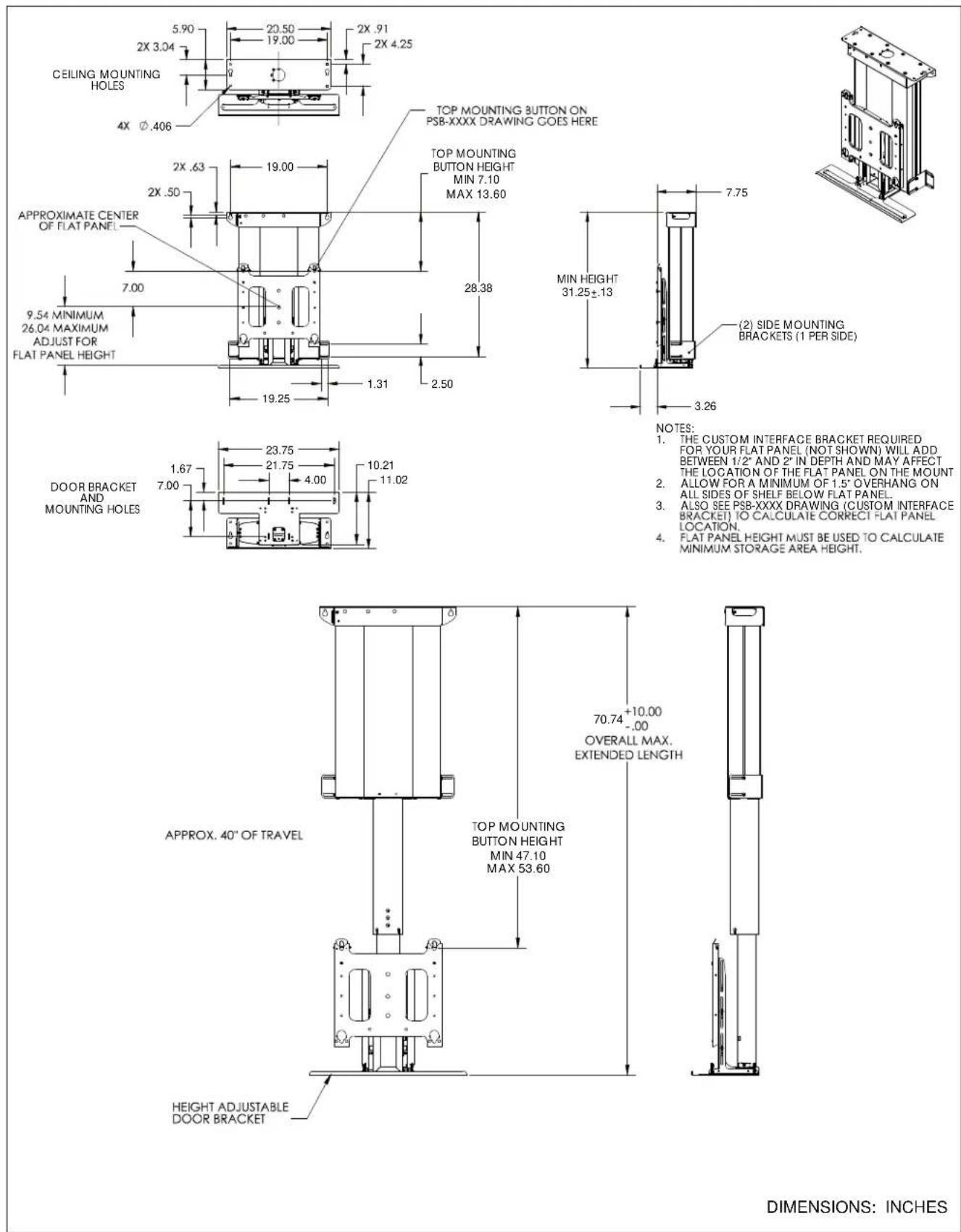
NOTES:
1. THE CUSTOM INTERFACE BRACKET REQUIRED FOR YOUR FLAT PANEL (NOT SHOWN) WILL ADD BETWEEN 1/2" AND 2" IN DEPTH AND MAY AFFECT THE LOCATION OF THE FLAT PANEL ON THE MOUNT
2. ALLOW FOR A MINIMUM OF 1.5" OVERHANG ON ALL SIDES OF SHELF BELOW FLAT PANEL.
3. ALSO SEE PSB-XXXX DRAWING (CUSTOM INTERFACE BRACKET) TO CALCULATE CORRECT FLAT PANEL LOCATION.
4. FLAT PANEL HEIGHT MUST BE USED TO CALCULATE MINIMUM STORAGE AREA HEIGHT.
DIMENSIONS: INCHES
LEGEND
The CM2C40 has been designed to be mounted either hanging from an overhead structure or mounted to existing stud wall structures.

WARNING: IMPROPER INSTALLATION CAN LEAD TO LIFT TIPPING CAUSING SEVERE PERSONAL INJURY OR DAMAGE TO EQUIPMENT! It is the installers responsibility to make certain the structure to which the lift is being mounted is capable of supporting 4 times the weight of the lift and all attached equipment.
Power Requirements and Wiring
The CM2C40 requires 120VAC (220/240VAC 50 Hz for European installations) power to operate.
A 6' long power cable is provided with the mount.
INSTALLATION
Pre-Installation Configuration and Adjustments
Prior to being installed, the CM2C40 requires the configuration of the mount for display, cable installation and routing, and the rough adjustment of the top cover mounting bracket.
To prepare the CM2C40 for Installation:
- Remove mount from box.
- Remove two wooden supports from under box.
- Lay two wooden supports on floor and mount CM2C40 to supports using four 5/16" flat washers and four 5/16" x 2-1/2" lag bolts (hardware provided). (See figure 1)

Figure 1
Configuring the Mount for the Display
Prior to installation, the CM2C40 needs to be configured for the size of the display being used.
To prepare the CM2C40 for the display being installed:
- Install interface bracket or mounting buttons to display following the instructions provided with bracket.
- Measure the distance from the center of an upper mounting button to the highest point of the display.
- Record measurement.
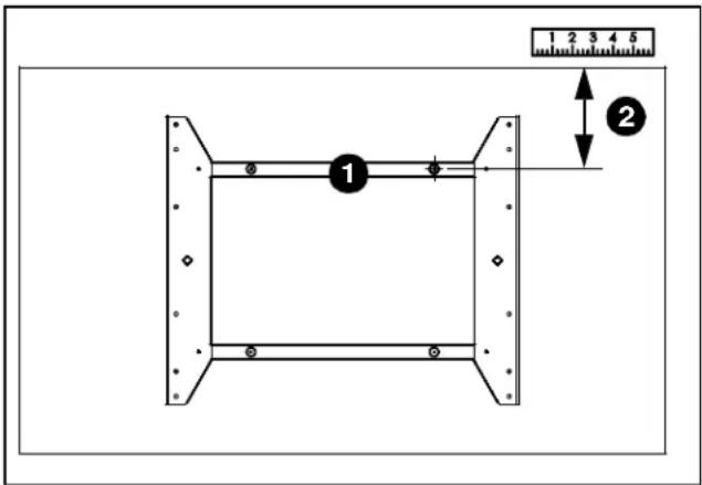
Figure 2
IMPORTANT ! : If the dimension taken in figure 2 is greater than 13.5" (342.9mm), the faceplate will need to be adjusted before mounting the display. If the dimension taken in figure 2 is less than 13.5" (342.9mm) proceed to Cable installation and Routing below.
Adjusting Faceplate Location
The CM2C40 is designed to allow up to 6.5" of adjustment. Up to 2" by adjusting the faceplate location on the faceplate mounting bracket, and up to an additional 4.5" by adjusting the faceplate mounting bracket.
Subtract 13.5" from the dimension determined in figure 2. The difference between the two is the total amount of adjustment the faceplate will require.
Example:
Dimension from Step 2 = 15"
15" - 13.5" = 1.5" (Amount of faceplate adjustment required)
If 2" or less faceplate adjustment is required proceed to step 5. If more than 2" of faceplate adjustment is required proceed to step 8.
NOTE: Depending upon the amount of faceplate adjustment required, it may be necessary to adjust both the faceplate and faceplate mounting bracket.
If 2" or less faceplate adjustment is required:
- Install IR receiver. (See figure 3)
- Plug appropriate power cord into mount and power source.
- Using the remote control, raise lift until locknuts on back side of faceplate can be accessed. (See figure 3)

WARNING: PINCH HAZARD! FINGERS OR HANDS BETWEEN MOVING PARTS CAN LEAD TO SEVERE PERSONAL INJURY! Keep fingers and hands away from mount when operating.

Figure 3
- Remove two locknuts securing faceplate to faceplate mounting bracket. (See figure 4)
- Move faceplate up one set of holes to adjust location 1" or two sets of holes to adjust 2". (See figure 4)

Figure 4
- Secure faceplate to faceplate mounting bracket using two locknuts. (See figure 6)

Figure 5
- Using the remote control, lower the lift until it stops. (See figure 3)
If more than 2" of faceplate adjustment is required:
- Raise lift following instructions in step 6. (See figure 3)
- Loosen four nuts securing faceplate mounting bracket to frame. (See figure 6)
- Move faceplate mounting bracket desired amount. (See figure 6)
NOTE: The CM2C40 is shipped with the faceplate mounting bracket installed in the lower slots. An additional 2" of faceplate adjustment can be obtained by moving the faceplate mounting bracket to the upper slots slots.
- Tighten four nuts to secure faceplate mounting bracket to frame.

WARNING: IMPROPER INSTALLATION CAN LEAD TO SEVERE PERSONAL INJURY OR DAMAGE TO EQUIPMENT! Make sure all four nuts are tight before continuing installation!
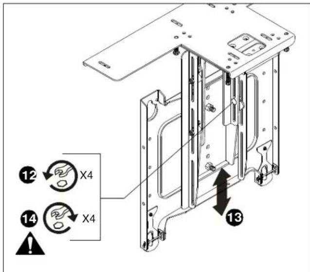
Figure 6
- Align studs in faceplate with appropriate holes in faceplate mounting bracket and hang faceplate on bracket with studs.
- Secure faceplate to faceplate mounting bracket using two locknuts. (See figure 7)

Figure 7
Cable Installation and Routing
The CM2C40 has an integrated cable management system that allows cables to be automatically "fed out" as the lift lowers, and "reeled in" as the lift raises while maintaining constant cable tension.
NOTE: Some components have been removed for clarity in the artwork associated with this procedure.
IMPORTANT ! : The CM2C40 requires minimum cable lengths of 8 feet from display through lower mount.
To install cables:
- Remove two screws securing cable guide side cover.
- Set screws aside for reuse. (See figure 8)
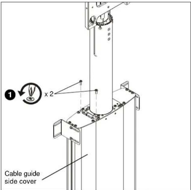
Figure 8
- Slide cable guide side cover away from mount and carefully set aside.
- Loosen three cable clamps. (See figure 10)
- Route cable(s) down through upper cable clamp. (See figure 10) and (See figure 11)
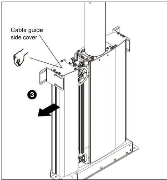
Figure 9
IMPORTANT ! : Evenly distribute cables between the four upper clamp locations to prevent tangling of cables and improper operation of CM2.
IMPORTANT ! : Leave enough cable length available above upper cable clamp to allow the routing and tie-down of cables between upper cable clamp and display.
- Route cable(s) down through opening behind cable pulley. (See figure 10) and (See figure 11)

CAUTION: DON'T TWIST CABLES! Damage to cables may occur if cables are twisted during cable management.
- Ensure that cables on rear side of CM2 (gray) stay towards rear side of cable pulley. (See figure 10) and (See figure 11)
- Ensure that cables on front side of CM2 (black) stay towards front side of cable pulley. (See figure 10) and (See figure 11)
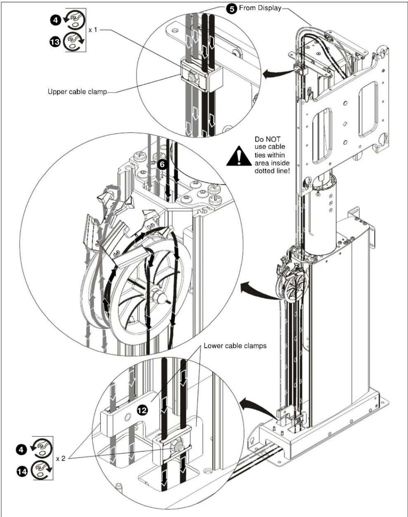
Figure 10

Figure 11
- Route cables under cable pulley and up over top of cable pulley. (See figure 10) and (See figure 11)
- Route one cable from front (black) cable clamps through the #2 cable opening and straight down next to the cable pulley center shaft. (See figure 10) and (See figure 11)
- Route one cable from front (black) cable clamps through the #3 cable opening and straight down next to the other side of the cable pulley center shaft. (See figure 10) and (See figure 11)
- Route one cable from rear (gray) cable clamps through the #2 cable opening and straight down next to the cable pulley center shaft. (See figure 10) and (See figure 11)
- Route one cable from rear (gray) cable clamps through the #3 cable opening and straight down next to the other side of the cable pulley center shaft. (See figure 10) and (See figure 11)
IMPORTANT ! : Ensure that cables are not twisted! Cables from front (black) of upper cable clamp (See figure 10) must be on front of cable pulley (See figure 11) and front of lower cable clamp (See figure 10). Cables from rear (gray) of upper cable clamp (See figure 10) must be on rear of cable pulley (See figure 11) and rear of lower cable clamp (See figure 10).
-
Continue routing cable(s) down through lower cable clamps. (See figure 10)
-
Tighten upper cable clamp making certain cables are properly seated in clamp and are not pinched.

CAUTION: OVERTIGHTENING OF CABLE CLAMPS CAN CRUSH CABLES LEADING TO DAMAGE TO EQUIPMENT! DO NOT over tighten cable clamps.
-
Starting at upper cable clamp and working downward, remove slack from all cables and tighten lower cable clamps. (See figure 10)
-
Slide cable guide side cover over CM2 mount lining up two holes in cable guide side cover with two holes in CM2 mount. (See figure 12)

Figure 12
- Secure cable guide side cover to CM2 mount using two screws (removed in Step 1). (See figure 13)
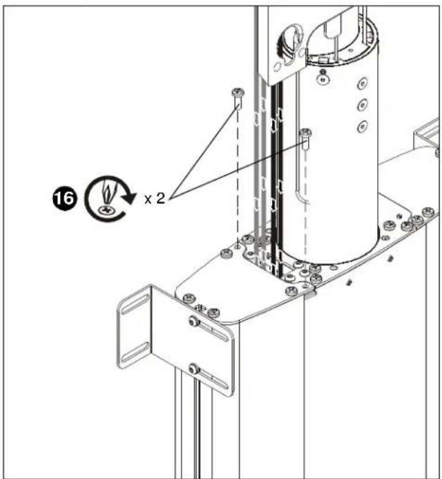
Figure 13
Mount Installation
The CM2C40 has been designed to be mounted either hanging from an overhead structure or mounted to existing stud wall structures. The following instructions assume a suitable mounting structure and surface exists prior to installation and all power and signal wires and cables have been properly installed.
IMPORTANT ! : The mounting pattern on the CM2C40 is 19" (483 mm) wide. If being mounted to an existing wall with 16" studs an additional stud will need to be added to each side in order for the mount to be installed.

WARNING: IMPROPER INSTALLATION CAN LEAD TO LIFT FALLING CAUSING SEVERE PERSONAL INJURY OR DAMAGE TO EQUIPMENT! It is the installers responsibility to make certain the structure to which the lift is being mounted is capable of supporting 4 times the weight of the lift and all attached equipment.
To install the CM2C40:
- If the display is installed and cables routed, disconnect wires and cables from display, and remove display.
- Remove mount from wooden supports used during mount setup and configuration. and orient mount as shown in figure below.

WARNING: MOUNT WEIGHS IN EXCESS OF 40LBS!
Always use two people and proper lifting techniques when installing or positioning mount.
-
Align mounting holes in baseplate with studs making sure mounting holes are centered on studs.
-
Locate vertical and horizontal position of mount. (See figure 15)
NOTE: The mount is designed to continue traveling 1/2" after the bottom cover makes contact with an object when being raised. If it is desired to use this feature this 1/2"
of travel must be considered when location the mount and a stop bar must be installed along the top edge of the opening in the ceiling. The stop bar must span the entire width of the front and back openings, and protrude outward into the opening a minimum of 1/2". See Bottom Cover Location Adjustmentsection and (See figure 27)
-
Loosen four screws securing side mounting brackets to mount and adjust side mounting brackets until properly positioned against studs if applicable. (See figure 16)
-
Tighten four screws to hold position of side mounting brackets. (See figure 14)
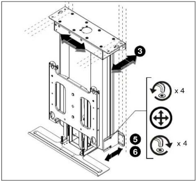
Figure 14

Figure 15
- While maintaining dimensions referenced in figure 15, mark base plate mounting hole locations. (See figure 16)
- Drill pilot holes at marked locations.
- Mark four side bracket mounting hole locations if applicable. (See figure 16)
- Drill four pilot holes at marked locations.
- Secure base plate to structure using either two (wall mount) or six (ceiling mount) 5/16" flat washers and two or six six 5/16" x 2 1/2" lag screws. (See figure 16)
- Secure side brackets, if applicable, to studs using four 5/16" flat washers and four 5/16" x 2 1/2" lag screws. (See figure 16)
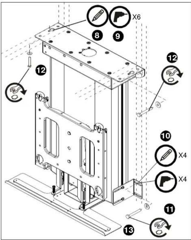
Figure 16
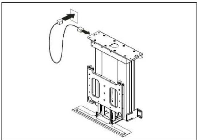
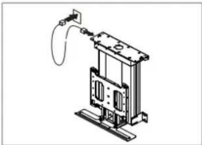
- Connect mount power cord to outlet.
natural_image
Technical line drawing of a mechanical assembly with mounting base and wiring (no text or symbols)Figure 17
Display Installation

WARNING: EXCEEDING MAXIMUM WEIGHT CAPACITY CAN LEAD TO SERIOUS PERSONAL INJURY OR DAMAGE TO EQUIPMENT! It is the installers responsibility to ensure the total amount of weight placed on the mount does not exceed 190lbs (86.18 kg) the maximum capacity of the CM2C40.

WARNING: PINCH HAZARD! FINGERS OR HANDS BETWEEN MOVING PARTS CAN LEAD TO SEVERE PERSONAL INJURY! Keep fingers and hands away from mount when operating.

WARNING: IMPROPER INSTALLATION CAN LEAD TO MOUNT FALLING CAUSING SEVERE PERSONAL INJURY OR DAMAGE TO EQUIPMENT. Displays can weigh in excess of 40 lbs (18.1kg). ALWAYS use two people and proper lifting techniques when installing display.

WARNING: IMPROPER INSTALLATION CAN LEAD TO MOUNT FALLING CAUSING SEVERE PERSONAL INJURY OR DAMAGE TO EQUIPMENT. Make sure mounting buttons on display are properly seated in mounting holes in faceplate.
To install display:
- Lower lift using the remote control provided.
- While supporting both sides of display, align four mounting buttons on display or interface bracket with four mounting holes in faceplate. (See figure 18) and (See figure 19)
- Lower display into place listening for audible "click" to ensure recessed area of mounting buttons are properly seated in lower area of mounting holes and "click lock" mechanism has engaged. (See figure 18) and (See figure 19)
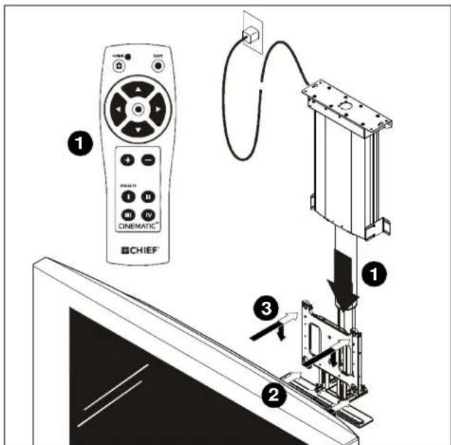
Figure 18
NOTE: Holes are provided in the faceplate for use with a padlock or similar locking device, if desired. In addition, the pin and nut may be removed from the upper holes and moved to the lower holes for use as a more permanent locking device. (See figure 19)

Figure 19
- Loosen four nuts securing right and left hand bottom cover adjustment brackets to faceplate mounting bracket. (See figure 20)
- Slide bottom cover adjustment brackets upward or downward until lip on bracket is positioned 1/4" below the bottom of display. (See figure 21)
- Tighten four nuts to secure bracket in position. (See figure 20)

WARNING: IMPROPER INSTALLATION CAN LEAD TO SEVERE PERSONAL INJURY OR DAMAGE TO EQUIPMENT! Make sure all four nuts are tight before continuing installation!
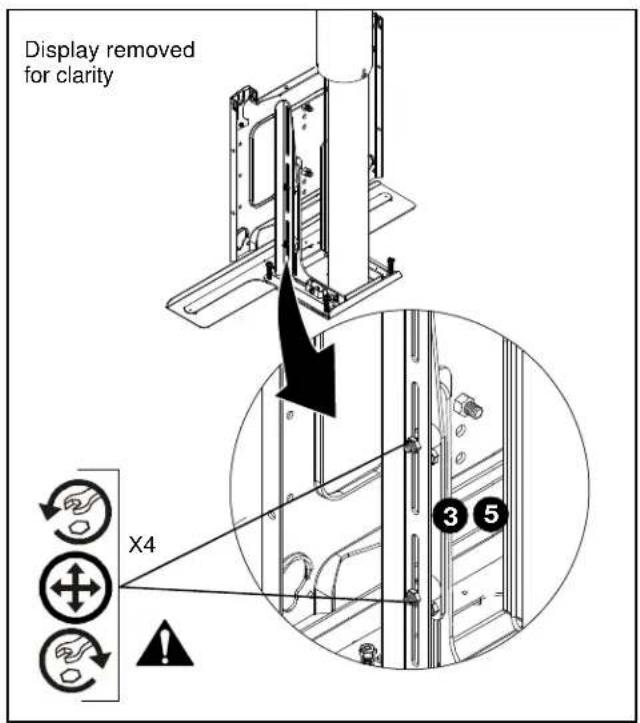
Figure 20

Figure 21
Bottom Cover Installation
After the CM2C40 has been properly configured for the display and the display installed, the bottom cover height must be adjusted to ensure proper fit into ceiling.

WARNING: IMPROPER INSTALLATION CAN LEAD TO SEVERE PERSONAL INJURY OR DAMAGE TO EQUIPMENT! Weight of bottom cover MUST NOT exceed 25 lbs (11.34kg).
To install the bottom cover :
- Measure the distance between the bottom of bottom cover mounting plate and the top edge of the opening in the ceiling and record dimension for future use.

Figure 22
- If the dimension identified during step 1 above is equal to or less than the thickness of the bottom cover being installed, the display travel limits must be adjusted before continuing to avoid a collision scenario between the bottom cover and the ceiling. Refer to step 6 below.
- If the dimension identified during step 1 above greater than the thickness of the bottom cover being installed, lower the display using the remote control until locknuts securing right and left cover adjustment brackets can be accessed. (See figure 23)

Figure 23
- Prepare bottom cover by cutting to appropriate size, allowing for clearance between cover and opening in ceiling, and drilling 6 through holes using the dimensions and pattern in the figure below. (See figure 24)

Figure 24
- Assemble bottom cover to cover mounting plate using #10-24 screws a minimum of 1/4" plus the thickness of the cover material long. (not provided). (See figure 25)

Figure 25
Bottom Cover Location Adjustment
The CM2C40 is designed to allow the adjustment of both "Extend" and "Retract" display travel limits. The CM2C40 is shipped set at maximum extension and retraction.
NOTE: The mount is designed to continue traveling 1/2" after the bottom cover makes contact with an object when being raised. If it is desired to use this feature when installing the bottom cover a stop bar must be installed along the top edge of the opening in the ceiling. The stop bar must span the entire width of the front and back openings, and protrude outward into the opening a minimum of 1/2". This 1/2" of travel must be taken into consideration during mount installation. (see page 10)
There is an upward travel limit adjustment screw and a downward travel limit adjustment screw located on the top right hand side of the mount. (See figure 27)
NOTE: 10 full turns of the "Extend" or "Retract" travel adjustment screws is equal to 1" of display travel.
- Turning the "Extend" travel adjustment screw clockwise will increase the amount of display downward travel. Turning the "Extend" adjustment screw counter-clockwise will decrease the amount of display downward travel.
- Turning the "Retract" travel adjustment screw clockwise will decrease the amount of display upward travel. Turning the "Retract" adjustment screw counter-clockwise will increase the amount of display downward travel.
- Adjust travel until bottom cover is flush with ceiling. (See figure 26) and (See figure 27)

Figure 26

Figure 27
Lift Column Bearing Adjustment
The upper and lower lift columns are aligned using two lift bearings, one upper and one lower.
Bearing adjustment is pre-set at the factory, however, there may be times when it is required to make slight adjustments in bearing tightness to eliminate excess play in lift columns or noise.

WARNING: OVERTENSIONING CAN LEAD TO DAMAGE TO EQUIPMENT! DO NOT overadjust!
IMPORTANT ! : Display should be installed on mount prior to performing lift column bearing adjustment!
To adjust lift column bearings:
- Determine if it is the upper or lower lift column that requires adjustment.
- Using a hex wrench, turning in small increments evenly across all adjustment screws, loosen or tighten adjustment screws.
- Run lift to fully up, and fully down position and verify proper lift column movement.
- Repeat steps 1 through 3 until desired lift column movement is achieved.

Extended Programming Capabilities
The CM2C40 allows for extended programming to make the mount compatible with other devices such as a Universal Remote or other control devices through a serial connection.
Setting or changing the configuration of the CM2C40 is done through the remote control provided with the mount.
The remote control has a range of 20-30ft (6-9m), and is powered by 2 AAA batteries that are accessed from the back of the remote.
NOTE: If operation of the mount is required at a greater distance than remote control will allow, the mount can be controlled through a hardwired switch or similar device. See Dry Contact Closures and (See figure 31).
The following table and illustration identify mount functionality and response by button on the remote control(s).
Normal Operating Mode

| KEY FUNCTION REQUIRED ACTION | |
| 1 NOT USED N/A | |
| 2 NOT USED N/A | |
| 3 EXTEND DISPLAY PRESS | |
| 4 NOT USED N/A | |
| 5 STOP PRESS | |
| 6 NOT USED N/A | |
| 7 RETRACT DISPLAY PRESS | |
| 8 NOT USED N/A | |
| 9 NOT USED N/A | |
| 10 NOT USED N/A | |
| 11 NOT USED N/A | |
| 12 NOT USED N/A | |
| 13 NOT USED N/A | |
Figure 28
IR-SE15 Programming
IR-SE15 Control Features:
• Carrier Frequency:38KHz
- Protocol:NEC - Full Repeat
- System Code(s):6E (Default) - Multiple Codes
Selected via Key-Press (see below)
Table 1: IR-SE15 Control Codes
| KEY FUNCTION HEX CODE | ||
| 1 NOT USED N/A | ||
| 2 NOT USED N/A | ||
| 3 EXTEND DISPLAY 07 | ||
| 4 NOT USED N/A | ||
| 5 STOP 0A | ||
| 6 NOT USED N/A | ||
| 7 RETRACT DISPLAY 0D | ||
| 8 NOT USED N/A | ||
| 9 NOT USED N/A | ||
| 10 | NOT USED N/A | |
| 11 | NOT USED N/A | |
| 12 | NOT USED N/A | |
| 13 | NOT USED N/A | |
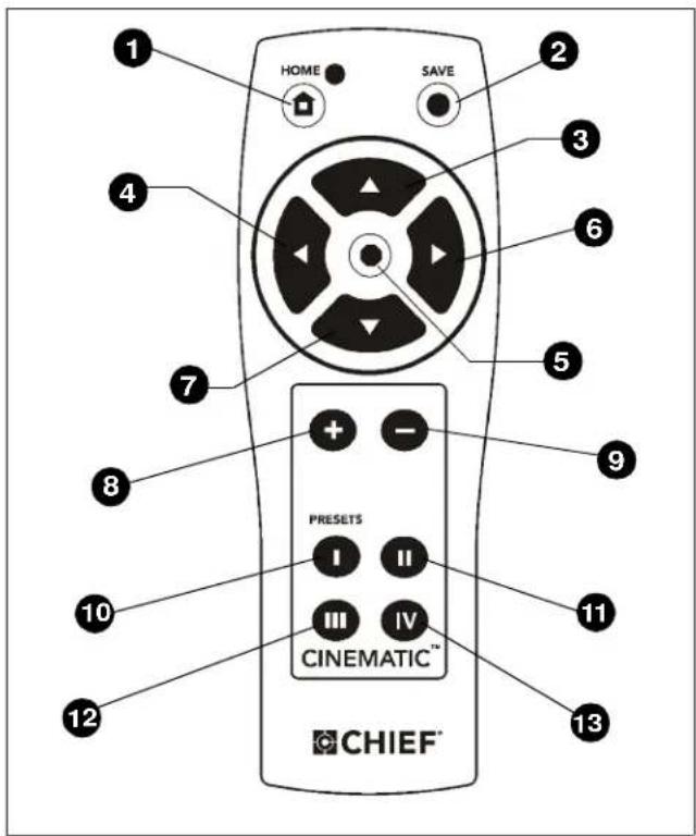
Figure 29
To Change System Code:
- Press and Release Key 3 + 7 (Enter Setup Mode)
- Press and Release Key 10
- Press and Release Key 11 - LED Blinks Twice
- Select System Code - See Table Below
- Press and Release Key 2 - LED Blinks 4 times
(Exit Setup Mode)
Table 2:
| System Code | Press + Release |
| 6E (Default) 10, 10 | |
| E1 10, 13 | |
| E2 11, 11 | |
| E3 11, 12 | |
| E4 11, 13 | |
| E5 12, 12 | |
| E6 12, 13 | |
| E7 13, 13 | |
Serial Communications
NOTE: Check with the appropriate automation system vendor for available drivers and/or software for any external devices.
Notes:
[PR] = Product ID (CM2C40 = 0 2)
[AD] = Address (see address description \ amp; table)
[CR] = ASCII Carriage Return
[CH] = Check Code
[ST] = Status (see status table)
Connections to be made to 9 pin connector as follows:
| RS-485 REF Pin 7 |
| RS-485 + Pin 9 |
| RS-485 - Pin 8 |
Communication parameters as specified in ANSI TIA/EIA-485-A:
| Baud Rate: 9600 | |
| Data Length: 8 Bits | |
| Parity: None | |
| Stop Bit: 1 | |
| Flow Control: None | |
Address Description
Multiple Chief devices can be used on the same network by setting each device to a different address.
NOTE: All units ship with a default address of 00.
NOTE: Broadcast messages will command all devices on the same network.
SERIAL CONTROL COMMAND STRING
| Start of Message (HEX) | Product ID (HEX) | Address (HEX) | Command (HEX) | Message Data (HEX) | Check Code (HEX) | End of Message (HEX) |
| > | XX | XX | XX | XX | XX | [Carriage Return] |
• Product ID for the CM2C40: 02
- Address controlled by dip switch settings
• Basic Commands available for the CM2C40 in the factory-supplied configuration:
• 03: Cancel Move = >0500037D[Carriage Return]
• 10: Extend to End of Travel = >0500107B0D[Carriage Return]
• 12: Retract to End of Travel = >0500127D0D[Carriage Return]
- Message Data = The data is required for the available commands:
• 03: None
• 10: None
• 12: None
- Check Code is calculated.
For further information, reference the Advanced Programming document and the website calculator.

Figure 30
CM2C40 Interface Board Hardware Information
(See figure 30)
Dry Contact Closures
The unit provides dry contact outputs for system feedback, or to control other devices.
To complete circuits to external devices:
- Connect the common wire from your switch to terminal 7. (See figure 31)
- Connect the 'up' wire from your switch to terminal 5.
- Connect the 'down' wire from your switch to terminal 6.

Figure 31
| J1 | |
| Pin 1 Isolated | Extend/Retract Input (+) |
| Pin 2 Isolated | Extend/Retract Input (-) |
| Pin 3 Isolated | Voltage Sense Input (+) |
| Pin 4 Isolated | Voltage Sense Input (-) |
| Pin 5 24V DC | Supply Out (150ma Max.) |
| Pin 6 Ground | |
| Pin 7 RS485 Ref. | |
| Pin 8 RS485 (+) | |
| Pin 9 RS485 (-) | |
| J2 | |
| Pin 1 Not Used | |
| Pin 2 Not Used | |
| Pin 3 Not Used | |
| Pin 4 Not Used | |
| Pin 5 Move Ext | end Terminal Input |
| Pin 6 Move Ret | ract Terminal Input |
| Pin 7 Ground | |
| Pin 8 Extend E | ror Input |
| Pin 9 Retract E | ror Input |
| Pin 10 Ground | |
| Pin 11 Extend L | mit Out |
| Pin 12 Extend L | imit Out Return |
| Pin 13 Retract L | limit Out |
| Pin14 Retract L | mit Out Return |
Other Dry Contact Options
Extend Retract with Single Switch
Using 9 pin Connector. (See figure 30) and (See figure 32)

Figure 32
Voltage Sense External Power Source
Unit extends and stays extended when voltage from an external source is applied across pins 3 and 4 on connector J1. When voltage is removed unit retracts. (See figure 30) and (See figure 33)

Figure 33
Voltage Sense Internal 24V DC Power Source
The 24V DC power supply that is built into the unit can be used to power external devices by using pins 5 and 6 on connector J1.
NOTE: Using this input will force a complete UP/DOWN cycle of the unit. No other inputs, with the exception of error inputs, are available until the cycle has completed. (See figure 30) and (See figure 34)

Figure 34
Extend Error Input
NOTE: Units are shipped with error contacts "Normally Open". To set unit to respond to "Normally Closed" error contacts contact a Chief Technical Support representative.
When unit receives an Extend error signal during an extend operation, the unit will immediately stop and reverse direction. (See figure 30) and (See figure 35)

Figure 35
Retract Error Input
NOTE: Units are shipped with error contacts "Normally Open". To set unit to respond to "Normally Closed" error contacts contact a Chief Technical Support representative by calling 1-800-582-6480, or by visiting www.chiefmfg.com.
When unit receives a Retract error signal during a Retract operation, the unit will immediately stop and reverse direction. (See figure 30) and (See figure 36)

Figure 36
Extend Limit Option
Internal set of dry contacts close when unit is fully extended.
Contact Rating: 30V AC or DC 1A max.
(See figure 30) and (See figure 37)

Figure 37
Retract Limit Option
Internal set of dry contacts close when unit is fully retracted.
Contact Rating: 30V AC or DC 1A max.
(See figure 30) and (See figure 38)

Figure 38
NOTE: Multiple control features can be used at the same time with the exception of the "Voltage Sense" feature.
Example: IR or Serial control along with a momentary pushbutton for service and a discreet UP/Down wall switch for operation.
IMPORTANT ! : When using multiple control features make sure ALL contacts are momentary and "Normally OPEN"
Connector and Switch Assignments
All Dipswitches are in the "OFF" position when shipped from factory.
| SW1 | |
| Switch 1 IR | |
| Switch 2 IR | |
| Switch 3 IR | |
| Switch 4 Not Used | |
| Switch 5 Not Used | |
| Switch 6 485 Address | |
| Switch 7 485 Address | |
| Switch 8 485 Address | |
| IR System Code Select Logic | |||
| Switch Settings (Sw 1-3) | |||
| Select 2 Select 1 Select 0 IR System Code | |||
| OFF OFF | OFF 6E | ||
| OFF OFF | ON | E1 | |
| OFF | ON | OFF E2 | |
| OFF | ON | ON | E3 |
| ON | OFF OFF | E4 | |
| ON | OFF ON | E5 | |
| ON | ON | OFF E6 | |
| ON | ON | ON | E7 |
| RS485 Address Select Logic | |||
| Switch Settings (Sw 6-8) | |||
| Select 2 | Select 1 | Select 0 | RS485 Network Address |
| OFF OFF | OFF | 00 | |
| OFF OFF | ON | 01 | |
| OFF | ON | OFF | 02 |
| OFF | ON | ON | 03 |
| ON | OFF | OFF | 04 |
| ON | OFF ON | 05 | |
| ON | ON | OFF | 06 |
| ON | ON | ON | 07 |
Troubleshooting
| SYMPTOM POSSIBLE CAUSE CORRECTIVE ACTION | ||
| Lift does not respond | No Power to Mount12V trigger option being usedOverheated motor | Verify Power to MountNormal OperationSee "Low Voltage Sensing" sectionAllow motor to cool for 10 to 15 minutes |
natural_image
Technical line drawing of a monitor assembly with a mounted frame and display panel (no text or symbols)PIEZAS

REFERENCIAS
Figura 5
Figura 7
Figura 14
Figura 16
natural_image
Technical line drawing of a mechanical assembly with mounting base and wiring (no text or symbols)Figura 17
Figura 18
Figura 26

Figura 37
Figura 38
natural_image
Technical line drawing of a mechanical assembly with a mounted bracket and two monitors (no text or symbols)КОМПОНЕНТЫ

natural_image
Three simple line drawings: a solar panel with rotation arrow, a device with switch and control panel, and a remote control panel (no text or symbols)natural_image
Technical line drawing of a mechanical assembly with no visible text or symbolsПРИМЕЧАНИЕ.
рис. 7
natural_image
Technical line drawing of a mechanical device with mounting base and wiring (no text or symbols)рис. 17
Установка монитора

рис. 18
рис. 26

рис. 37
рис. 38
MANUFACTURERS DECLARATION OF CONFORMITY
PRODUCT IDENTIFICATION:
| Model/Type | : | CM2L40I, CM2L40UI – TV LiftCM2C40I, CM2C40UI – TV Ceiling Mount |
| Category (description) | : | Mounting devices, Stands and other Accessories, to be used with entertainment electronics |
| Brand | : | Chief |
| Manufacturer | : | Milestone AV Technologies8401 Eagle Creek ParkwaySavage, MN 55378 |
| EU Representative | : | Milestone AV TechnologiesFellennoord 130 S611ZB EinhovenThe Netherlands31 (0)20 5708923 |
| Concerning | EMC | Safety (TV Lifts) | Safety (TV Ceiling Mount) |
| A sample of the product has been tested by | TUV SUD America0123 | TUV SUD America0123 | Milestone Test Lab |
| Test report reference | NC707785WC700711,WC603563 | DE 3 - 84051 | 00463 |
| Applied standards | EN500228, | EN 60065/A1:2005 | EN 60065/A1:2005 |
- IMPORTANT WARNINGS AND CAUTIONS!
- "SAVE THESE INSTRUCTIONS"
- DANGER: TO REDUCE THE RISK OF ELECTRIC SHOCK:
- CONTENTS
- TOOLS REQUIRED FOR INSTALLATION
- PARTS
- Power Requirements and Wiring
- INSTALLATION
- Pre-Installation Configuration and Adjustments
- Configuring the Mount for the Display
- Adjusting Faceplate Location
- Example:
- If more than 2" of faceplate adjustment is required:
- Cable Installation and Routing
- Mount Installation
- Display Installation
- Bottom Cover Installation
- Bottom Cover Location Adjustment
- Lift Column Bearing Adjustment
- Extended Programming Capabilities
- IR-SE15 Programming
- Serial Communications
- Address Description
- CM2C40 Interface Board Hardware Information
- Dry Contact Closures
- Other Dry Contact Options
- Extend Retract with Single Switch
- Voltage Sense External Power Source
- Voltage Sense Internal 24V DC Power Source
- Extend Error Input
- Retract Error Input
- Extend Limit Option
- Retract Limit Option
- Connector and Switch Assignments
- PIEZAS
- КОМПОНЕНТЫ
- ПРИМЕЧАНИЕ.
- Установка монитора
- MANUFACTURERS DECLARATION OF CONFORMITY
- PRODUCT IDENTIFICATION:
Brand : Chief
Model : CM2C40U
Category : Flat Screen Mount