
PE5101D - Computer ASUS - Free user manual and instructions
Find the device manual for free PE5101D ASUS in PDF.
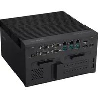


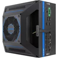
| Product Type | Embedded Computer / Industrial PC |
| Dimensions (approx.) | 280 x 200 x 80 mm (estimate) |
| Weight (approx.) | 5 kg (estimate) |
| Power Input | 8-48 VDC, 330 W max (adapter 100-240 VAC) |
| Display Outputs | 1x HDMI (up to 4096x2160 @30Hz), 1x DisplayPort 1.2 (up to 4096x2160 @60Hz) |
| USB Ports | 6x USB 10Gbps (front), 2x USB 5Gbps (rear), 2x USB 2.0 (rear) |
| LAN Port | 1x 2.5G Ethernet (RJ-45) |
| Serial Ports | 4x RS-232/422/485 (DB9) on front, 2x RS-232 (DB9) on rear |
| Expansion Slots | 1x M.2 M-key (PCIe Gen4 x4, 2280), 1x M.2 B-key (USB 3.2/PCIe, 3042/3052), 1x M.2 E-key (Wi-Fi, 2230), 1x mPCIe, 1x PCIe Gen4 x16 (via riser), 1x PCIe Gen4 x4 (via riser) |
| Storage | 2x 2.5-inch hot-swap SATA drives (7-7.5mm), 1x SATA 6Gb/s internal connector |
| Memory | 2x SO-DIMM DDR5 (ECC supported), up to 64 GB total |
| Watchdog Timer | POST watchdog timer, programmable via BIOS and software |
| Audio | 1x Microphone input (rear), 1x Audio output (rear) |
| Antenna | 6x antenna jacks (front/side) for Wi-Fi, 4G/5G modules |
| Isolated DIO | Optional: 4 digital inputs, 4 digital outputs, isolated (0-48 VDC, 4A) |
| Operating Temperature | -25°C to 60°C with adequate airflow |
| Power Adapter | 330 W UL-certified, input 100-240 VAC, output 24 VDC (terminal block) |
| Wall Mount Kit | Included (brackets and dampers) |
| Safety Certification | FCC Class A, CE, UKCA, ISED, KC, etc. |
| Maintenance & Cleaning | Disconnect power, clean with dry cloth; avoid liquids |
| Reparability/Spare Parts | Modular design; memory, storage, Wi-Fi, cellular, GPU, antennas, fan, battery user-replaceable |
| Environmental Compliance | EU RoHS, REACH, WEEE, India/Vietnam RoHS |
Frequently Asked Questions - PE5101D ASUS
User questions about PE5101D ASUS
0 question about this device. Answer the ones you know or ask your own.
Ask a new question about this device
Download the instructions for your Computer in PDF format for free! Find your manual PE5101D - ASUS and take your electronic device back in hand. On this page are published all the documents necessary for the use of your device. PE5101D by ASUS.
USER MANUAL PE5101D ASUS
No part of this manual, including the products and software described in it, may be reproduced, transmitted, transcribed, stored in a retrieval system, or translated into any language in any form or by any means, except documentation kept by the purchaser for backup purposes, without the express written permission of ASUSTeK COMPUTER INC. ("ASUS").
ASUS PROVIDES THIS MANUAL "AS IS" WITHOUT WARRANTY OF ANY KIND, EITHER EXPRESS OR IMPLIED, INCLUDING BUT NOT LIMITED TO THE IMPLIED WARRANTIES OR CONDITIONS OF MERCHANTABILITY OR FITNESS FOR A PARTICULAR PURPOSE. IN NO EVENT SHALL ASUS, ITS DIRECTORS, OFFICERS, EMPLOYEES OR AGENTS BE LIABLE FOR ANY INDIRECT, SPECIAL, INCIDENTAL, OR CONSEQUENTIAL DAMAGES (INCLUDING DAMAGES FOR LOSS OF PROFITS, LOSS OF BUSINESS, LOSS OF USE OR DATA, INTERRUPTION OF BUSINESS AND THE LIKE), EVEN IF ASUS HAS BEEN ADVISED OF THE POSSIBILITY OF SUCH DAMAGES ARISING FROM ANY DEFECT OR ERROR IN THIS MANUAL OR PRODUCT.
Products and corporate names appearing in this manual may or may not be registered trademarks or copyrights of their respective companies, and are used only for identification or explanation and to the owners' benefit, without intent to infringe.
SPECIFICATIONS AND INFORMATION CONTAINED IN THIS MANUAL ARE FURNISHED FOR INFORMATIONAL USE ONLY, AND ARE SUBJECT TO CHANGE AT ANY TIME WITHOUT NOTICE, AND SHOULD NOT BE CONSTRUED AS A COMMITMENT BY ASUS. ASUS ASSUMES NO RESPONSIBILITY OR LIABILITY FOR ANY ERRORS OR INACCURACIES THAT MAY APPEAR IN THIS MANUAL, INCLUDING THE PRODUCTS AND SOFTWARE DESCRIBED IN IT.
Copyright © 2024 ASUSTeK COMPUTER INC. All Rights Reserved.
LIMITATION OF LIABILITY
Circumstances may arise where because of a default on ASUS' part or other liability, you are entitled to recover damages from ASUS. In each such instance, regardless of the basis on which you are entitled to claim damages from ASUS, ASUS is liable for no more than damages for bodily injury (including death) and damage to real property and tangible personal property; or any other actual and direct damages resulted from omission or failure of performing legal duties under this Warranty Statement, up to the listed contract price of each product.
ASUS will only be responsible for or indemnify you for loss, damages or claims based in contract, tort or infringement under this Warranty Statement.
This limit also applies to ASUS' suppliers and its reseller. It is the maximum for which ASUS, its suppliers, and your reseller are collectively responsible.
UNDER NO CIRCUMSTANCES IS ASUS LIABLE FOR ANY OF THE FOLLOWING: (1) THIRD-PARTY CLAIMS AGAINST YOU FOR DAMAGES; (2) LOSS OF, OR DAMAGE TO, YOUR RECORDS OR DATA; OR (3) SPECIAL, INCIDENTAL, OR INDIRECT DAMAGES OR FOR ANY ECONOMIC CONSEQUENTIAL DAMAGES (INCLUDING LOST PROFITS OR SAVINGS), EVEN IF ASUS, ITS SUPPLIERS OR YOUR RESELLER IS INFORMED OF THEIR POSSIBILITY.
SERVICE AND SUPPORT
Visit our multi-language website at https://www.asus.com/support/.
Contents
About this manual....5
Conventions used in this manual....6
Package contents ....7
Chapter 1: Getting to know your Embedded Computer
1.1 Features....10
1.1.1 Front view 10 1.1.2 Rear view.... 16 1.1.3 Left view 19 1.1.4 Right view 20
1.2 Motherboard & riser card overview....21
1.2.1 Motherboard layout.... 21 1.2.2 Onboard jumpers.... 23 1.2.3 Internal connectors 25 1.2.4 Riser card layout 34 1.2.5 Riser card connectors 35
Chapter 2: Using your Embedded Computer
2.1 Getting started....38
2.1.1 Connect the AC power adapter to your Embedded Computer 38 2.1.2 Connect a display panel to your Embedded Computer 40 2.1.3 Connect the USB cable from keyboard or mouse 42 2.1.4 Turn on your Embedded Computer 43
2.2 Turning off your Embedded Computer....44
2.3 Installing wall mount brackets....45
Chapter 3: Upgrading your Embedded Computer
3.1 Installing a storage device 48 3.2 Removing the bottom cover....50 3.3 Replacing the bottom cover 52 3.4 Removing the heat spreader ....53 3.5 Installing memory modules....56
3.6 Installing an M.2 SSD module to the M.2 M-key slot....57 3.7 Installing a wireless card to the M.2 E-key slot....58 3.8 Installing a cellular network module to the M.2 B-key slot....60 3.9 Installing an mPCIe module 65 3.10 Installing a nano SIM card....66 3.11 Installing a GPU card....68 3.12 Installing antennas (optional)....72
Chapter 4: Watchdog Timer
4.1 Watchdog Timer implementation....78 4.2 Watchdog Timer programming....79
Appendix
Safety information....84
Setting up your system....84
Care during use....85
Regulatory notices 87
Service and Support....97
About this manual
This manual provides information about the hardware and software features of your Embedded Computer, organized through the following chapters:
Chapter 1: Getting to know your Embedded Computer
This chapter details the hardware components of your Embedded Computer.
Chapter 2: Using your Embedded Computer
This chapter provides you with information on using your Embedded Computer.
Chapter 3: Upgrading your Embedded Computer
This chapter provides you with information on how to upgrade the memory modules, wireless modules, and hard disk drive / solid state drive of your Embedded Computer.
Chapter 4: Watchdog Timer
This chapter will guide you in implementing and programming the Watchdog Timer to allow you to monitor and manage system reliability.
Appendix
This section includes notices and safety statements for your Embedded Computer.
Conventions used in this manual
To highlight key information in this manual, some text are presented as follows:
IMPORTANT! This message contains vital information that must be followed to complete a task.
NOTE: This message contains additional information and tips that can help complete tasks.
WARNING! This message contains important information that must be followed to keep you safe while performing certain tasks and prevent damage to your Embedded Computer's data and components.
Package contents
Your Embedded Computer package contains the following items:

PE5101D


Power terminal block Wall mount kit with dampers


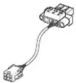
Remote power terminal block Expansion card power cable
Optional item(s)*

Terminal block, power adapter, power adapter and cord


Cellular network antenna, Wi-Fi antenna
NOTE:
- *These accessories are not bundled and need to be purchased separately.
- Some bundled accessories may vary depending on the model. For details on these accessories, refer to their respective user manuals.
- Illustrations of the device and accessories are for reference only. Actual product specifications may vary depending on the model.
- If the device or its components fail or malfunction during normal and proper use within the warranty period, bring the warranty card to the ASUS Service Center for replacement of the defective components.
1
Getting to know your Embedded Computer
1.1 Features
1.1.1 Front view

1 HDMI HDMI™ port with cable lock
The integrated HDMI (High Definition Multimedia Interface) port with a receptacle connector can support resolutions up to 4096 x 2160 @ 30 Hz on external display devices.
NOTE: The cable lock helps to prevent disconnection caused by tension or vibration.
2 ANT. Wireless antenna jack
The wireless antenna jack allows you to connect a wireless antenna.
NOTE: Wireless antennas are optional and may not come bundled.
3 :D1 Dual-mode DisplayPort
The DisplayPort 1.2 port can support resolutions up to 4096 x 2160 @ 60 Hz on external display devices.
4 10G USB 1 USB 10Gbps port
The USB (Universal Serial Bus) 10Gbps port provides a transfer rate up to 10 Gbit/s.
10G USB 2 10G USB 3
10G USB 4 10G USB 5 10G USB 6

2.5G LAN port
The 8-pin RJ-45 LAN port for 10/100/1000/2500 Mbps
connection to a Local Area Network (LAN).
LAN port LED indications

| Activity Link LED | |
| Status Description | |
| Off No link | |
| Green Linked | |
| Green (blinking) Data | activity |
| Green (blinking then steady) | Ready to wake up from suspend mode |
| Speed LED | |
| Status Description | |
| Off | 10/100 Mbps connection |
| Orange 1 Gbps connection | |
| Green 2.5 Gbps connection | |

COM1 COM2
Serial (COM) connector
The 9-pin DB9 connector allows you to connect RS-232/422/485 serial (COM) devices, such as bar code scanners, modems, and printers. Please refer to the table below for the pin definitions of the different COM connectors.
NOTE: Default set to RS-232. Setting can be changed through the BIOS.

| Pin RS-232 RS-422 RS-485 | ||
| 1 DCD# TX- D- | ||
| 2 RXD TX+ D+ | ||
| 3 TXD RX+ NA | ||
| 4 DTR RX- NA | ||
| 5 GND GND GND | ||
| 6 DSR NA NA | ||
| 7 RTS NA NA | ||
| 8 CTS NA NA | ||
| 9 RI | NA NA | |

COM3 COM4
Serial (COM) connector
The 9-pin DB9 connector allows you to connect RS-232 serial (COM) devices, such as bar code scanners, modems, and printers. Please refer to the table below for the pin definitions of the different COM connectors.

| Pin RS-232 |
| 1 DCD# |
| 2 RXD |
| 3 TXD |
| 4 DTR |
| 5 GND |
| 6 DSR |
| 7 RTS |
| 8 CTS |
| 9 RI |

HDD Drive activity LED
The drive activity LED lights up when your Embedded Computer is accessing the internal storage drive.
WDT Watchdog LED
The watchdog LED lights up when a watchdog time out event occurs.
IGN Ignition LED
The ignition LED lights up when your Embedded Computer is powered on and in ignition mode.
NOTE: The default BIOS setting for the ignition function is disabled.


Power button
The power button allows you to turn the Embedded Computer on or off. You can use the power button to put your Embedded Computer to sleep mode or press it for four (4) seconds to force shutdown your Embedded Computer.

HDD1 2.5-inch hot-swap storage bay
HDD2 The 2.5-inch hot-swap storage bay allows you to install a 2.5-inch HDD/SSD and supports RAID 0/1.

Expansion card slot
The expansion card slot allows you to install additional hardware components, such as graphics cards or network adapters.

Air vents
The air vents allow improved air ventilation.
IMPORTANT! For optimal heat dissipation and air ventilation, ensure that the air vents are free from obstructions.

RESET System reset pinhole
The hard reset pinhole allows you to reboot your Embedded Computer.
1.1.2 Rear view


Power input
The power input jack allows you to connect the bundled power terminal block.


Remote power connector
The remote power connector allows you to connect an external power button or switch.

Serial (COM) connector
The 9-pin DB9 connector allows you to connect RS-232 serial (COM) devices, such as bar code scanners, modems, and printers. Please refer to the table below for the pin definitions of the different COM connectors.

| Pin RS-232 |
| 1 DCD# |
| 2 RXD |
| 3 TXD |
| 4 DTR |
| 5 GND |
| 6 DSR |
| 7 RTS |
| 8 CTS |
| 9 RI |

USB 5Gbps port
The USB (Universal Serial Bus) 5Gbps port provides a transfer rate up to 5 Gbit/s.

USB 2.0 port
The USB (Universal Serial Bus) port is compatible with USB 2.0 or USB 1.1 devices, such as keyboards, pointing devices, flash disk drives, external HDDs, speakers, cameras, and printers.


Microphone input jack
The microphone input jack is used to connect your Embedded Computer to an external microphone.


Functional earth ground
The functional earth ground provides you with a grounding point.

Isolated DIO connector (optional)
The Isolated Digital Input/Output (DIO) connector provides electrical isolation of digital input and output signals, which allow microcontrollers to detect and output logic states. The high voltage protection can be used in industrial level uses. Please refer to the illustration below for the specification and pin definitions of the Isolated DIO connector.
| Signal Specifications | |
| DO | Output voltage range 0~48 VDC |
| Rated output current 4 A | |
| DI | Voltage for logic “0” 0~3 VDC |
| Voltage for logic “1” 10~48 VDC | |
| Rated input current ±50 mA | |
| Pin DIO Pin DIO | |||
| 1 DI_COM 9 DI1 | |||
| 2 DI_COM 10 DI2 | |||
| 3 DIO_GND 11 DI3 | |||
| 4 DIO_GND 12 DI4 | |||
| 5 DIO_GND 13 DO1 | |||
| 6 DIO_GND 14 DO2 | |||
| 7 DO_PWR 15 DO3 | |||
| 8 DO_PWR 16 DO4 | |||


Serial connector (optional)
The 9-pin DB9 connector allows you to connect additional serial devices.
10
Air vents
The air vents allow improved air ventilation.
IMPORTANT! For optimal heat dissipation and air ventilation, ensure that the air vents are free from obstructions.
11

Audio output jack
This stereo audio jack is used to connect the system's audio out signal to amplified speakers.
1.1.3 Left view

1.1.4 Right view


ANT. Wireless antenna jack
The wireless antenna jack allows you to connect a wireless antenna.
NOTE: Wireless antennas are optional and may not come bundled.
1.2 Motherboard & riser card overview
Refer to the table on the next page for the page numbers of the numbered items.
1.2.1 Motherboard layout

| Jumpers Page | |
| 1. COM +5V/+12V Selection jumper 23 | |
| 2. Clear RTC RAM jumper 24 |
| Connectors/slots Page | |
| 1. Mini PCIe slot 25 | |
| 2. Battery connector 25 | |
| 3. Riser card slot 26 | |
| 4. M.2 M-key slot 26 | |
| 5. SATA 6Gb/s connector 27 | |
| 6. SPI TPM connector 28 | |
| 7. M.2 B-key slot 28 | |
| 8. Nano SIM Card slot 29 | |
| 9. M.2 E-key (Wi-Fi) slot 29 | |
| 10. COM Debug connector 30 | |
| 11. 4-pin Power connector | 31 |
| 12. DIMM slot | 32 |
| 13. GPIO connector | 32 |
| 14. I2C connector | 33 |
1.2.2 Onboard jumpers
1. COM +5V/+12V Selection jumper
The COM +5V/+12V Selection jumper allows you to select the voltage for the COM1 and COM2 ports.

A COM2_SEL B COM1_SEL
+12V
+5V
RI
(Default)
2. Clear RTC RAM jumper
The Clear RTC RAM jumper allows you to clear the Real Time Clock (RTC) RAM in the CMOS, which contains the date, time, system passwords, and system setup parameters.
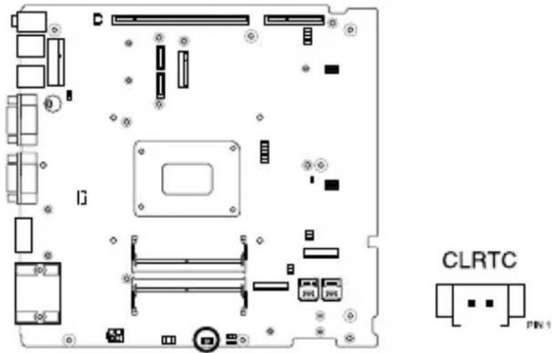
To erase the RTC RAM:
- Turn OFF the computer and unplug the power cord.
- Short-circuit pin 1-2 with a metal object or jumper cap for about 5-10 seconds.
- Plug the power cord and turn ON the computer.
- Hold down the key during the boot process and enter BIOS setup to re-enter data.
NOTE: If the steps above do not help, remove the onboard button cell battery and move the jumper again to clear the CMOS RTC RAM data. After clearing the CMOS, reinstall the button cell battery.
1.2.3 Internal connectors
1. Mini PCIe slot
The Mini PCIe slot allows you to install a Mini PCIe peripheral device.

NOTE:
• The Mini PCIe peripheral device is purchased separately. • We recommend using a PH1 screwdriver with a torque of 2.0 ± 0.2 kgf-cm when tightening the screws.
2. RTC Battery connector
The RTC Battery connector allows you to connect a lithium CMOS battery.

3. Riser card slot
The riser card slot supports a PCIe riser card that allows you to install a full-height, half-length (FHHL) PCIe Gen4 x16 expansion card and a FHHL PCIe Gen4 x4 expansion card. For more information on the riser card, refer to the Riser card layout section.


4. M.2 M-key slot
The M.2 M-key slot allows you to install an M-key (PCIe Gen4 x4), type 2280 M.2 device, such as an M.2 SSD module.


NOTE:
• The M.2 SSD module is purchased separately.
• We recommend using a PH1 screwdriver with a torque of 2.0 ± 0.2 kgf-cm when tightening the screw.
5. SATA 6Gb/s connector
The SATA 6Gb/s allows you to connect SATA devices, such as optical disc drives and hard disk drives via a SATA cable.


Connector type
Wafer HD 7p, 1.27mm pitch
NOTE: Ensure to use the bundled cable when connecting a storage device to this connector.
6. SPI TPM connector
The SPI TPM connector supports a Trusted Platform Module (TPM) system, which can securely store keys, digital certificates, passwords, and data. A TPM system also helps enhance network security, protects digital identities, and ensures platform integrity.

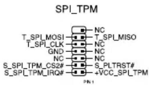
Connector type
Header 2x7p, K14, 2.0mm pitch
7. M.2 B-key slot
The M.2 B-key slot allows you to install a B-key (PCIe x1, USB 3.2 Gen 1, USB 2.0) type 3042/3052 M.2 device, such as a 4G LTE or 5G NR module.

NOTE:
• The M.2 4G LTE or 5G NR module is purchased separately.
• We recommend using a PH1/sleeve screwdriver with a torque of 2.0 ± 0.2 kgf-cm when tightening the screw/standoff.
8. Nano SIM Card slot
The Nano SIM Card slot allows you to install a Nano SIM card.
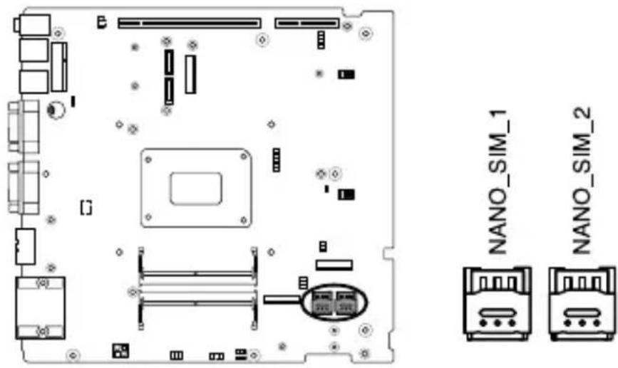
NOTE: Nano SIM cards are purchased separately.
9. M.2 E-key (Wi-Fi) slot
The M.2 E-key (Wi-Fi) slot allows you to install an E-key (PCIe, USB 2.0) type 2230 M.2 Wi-Fi module.

NOTE:
- The M.2 Wi-Fi module is purchased separately. • We recommend using a PH1 screwdriver with a torque of 2.0 ± 0.2 kgf-cm when tightening the screw.
10. COM Debug connector
The COM Debug connector allows you to connect a COM debug card.

Connector type
Header 2x3p, 2.54mm pitch
11. 4-Pin Power connector
The 4-pin Power connector allows you to supply power to an expansion card via an expansion card power cable.

Connector type
POWER CON 4P W/P
12. DIMM slot
The motherboard comes with a Small Outline Dual Inline Memory Module (SODIMM) slot designed for DDR5 (Double Data Rate 5) memory modules.


13. GPIO connector
The GPIO connector allows you to connect a general purpose input/output module to customize digital signal input/output.


Connector type
BOX header 2x5p, K9, 2.0mm pitch
14. I2C connector
The I2C (Inter-Integrated Circuit) connector allows you to connect an I2C-compatible IoT security module.
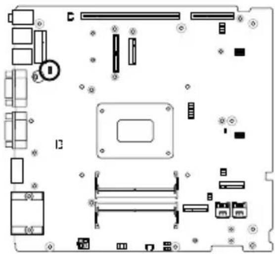

Connector type
Header 1x3p, K6, 2.0mm pitch
1.2.4 Riser card layout

| Connectors/slots Page | |
| 1. Chassis fan connector 35 | |
| 2. PCIe Gen4 x4 slot 36 | |
| 3. PCIe Gen4 x16 slot 36 |
1.2.5 Riser card connectors
The fan connector allows you to connect a fan to cool the system.


Connector type
WtoB CON 4P, 1.25mm, S/T
WARNING!
- DO NOT forget to connect the fan cable to the fan connector. Insufficient air flow inside the system may damage the motherboard components. These are not jumpers! Do not place jumper caps on the fan connectors! • Make sure that the cable is fully inserted into the connector.
2. PCIe Gen4 x4 slot
The PCIe Gen4 x4 slot supports full-height, half-length PCIe Gen4 x4 expansion cards.


3. PCIe Gen4 x16 slot
The PCIe Gen4 x16 slot supports full-height, half-length PCIe Gen4 x16 expansion cards.


Using your Embedded Computer
2
2.1 Getting started
2.1.1 Connect the AC power adapter to your Embedded Computer
To connect the AC power adapter to your Embedded Computer:
A. Connect the power cord to the AC power adapter. B. Connect the AC power adapter to the terminal block power adapter. C. Connect the 3-pin terminal block DC power connector into your Embedded Computer's power (DC) input. D. Plug the AC power adapter into a 100 V~240 V power source.
NOTE: The power adapter is purchased separately and may vary in appearance, depending on model and your region.

IMPORTANT!
We strongly recommend that you use only UL-certified power adapters and cables that meet the following requirements, or ones that you purchased as an option with your Embedded Computer.
330 W Power adapter (operating temperature 0°C to 40°C)
Input voltage: 100-240 Vac
Input frequency: 50-60 Hz
Output current: 13.75 A (330 W)
Output voltage: 24 Vdc
System (operating temperature -25°C to 60°C)
Rated voltage: 8-48 Vdc
Rated current: 41.25 A - 6.875 A (330 W)
We suggest using a power supply with 8 - 48 Vdc for DC-in that complies with the safety requirements of a regulated power source. We strongly recommend that you use a grounded wall socket while using your Embedded Computer. The socket outlet must be easily accessible and near your Embedded Computer. To disconnect your Embedded Computer from its main power supply, unplug your Embedded Computer from the power socket.
WARNING!
- Do not use power adapters or batteries from other devices to reduce the risk of injury to persons due to fire or explosion. Use only UL certified power adapters or batteries supplied by the manufacturer or authorized retailers.
- Do not disable or remove the power cord grounding plug, the grounding is an important safety feature.
- Make sure to plug the power cord into a grounded (earthed) electrical outlet that is easily accessible at all times.
2.1.2 Connect a display panel to your Embedded Computer
You can connect a display panel or projector to your Embedded Computer that has the following connector(s):
- HDMI™ connector
- DisplayPort
To connect a display panel to your Embedded Computer:
Connect one end of an HDMI™ or a DisplayPort cable to an external display, and the other end of the cable to your Embedded Computer's HDMI™ port or DisplayPort.
Connect display via HDMI™ port
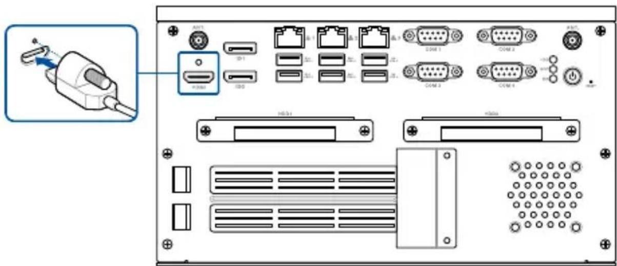
Connect display via DisplayPort

2.1.3 Connect the USB cable from keyboard or mouse
You can connect generally any USB keyboard and mouse to your Embedded Computer. You can also connect a USB dongle for a wireless keyboard and mouse set.
To connect a keyboard and mouse to your Embedded Computer:
Connect the USB cable from your keyboard and mouse to any of the USB ports of your Embedded Computer.
NOTE:
- The keyboard varies with country and/or region.
- The keyboard and mouse are purchased separately.

2.1.4 Turn on your Embedded Computer
Press the power button to turn on your Embedded Computer if it does not power on automatically when you connect it to a power source.

2.2 Turning off your Embedded Computer
If your Embedded Computer is unresponsive, press and hold the power button for at least four (4) seconds until your Embedded Computer turns off.
2.3 Installing wall mount brackets
- Insert the eight (8) dampers bundled with the wall mount kit into the keyhole slots on the wall mount brackets and slide them into the narrower channel of each hole for secure placement.
- Align the wall mount brackets to the screw holes on the bottom of your Embedded Computer, and then secure the wall mount brackets using the six (6) bundled screws.

3
Upgrading your Embedded Computer
3.1 Installing a storage device
You may install up to two (2) 2.5-inch storage devices (hot-swappable, 7~7.5mm) to your Embedded Computer.
- Loosen the two (2) screws securing each of the storage device trays to the right panel.
- Pull the storage device tray out of the chassis.

- Install your storage device to the storage device tray (A), then secure it with four (4) screws (B).

- Replace the storage device tray.
- Secure the storage device tray with the two (2) screws removed previously.
3.2 Removing the bottom cover
IMPORTANT!
- Ensure that your hands are dry before proceeding with the rest of the installation process. Before installing any of the features in this guide, use a grounded wrist strap or touch a safely grounded object or metal object to avoid damaging them due to static electricity.
- Turn off the power of your Embedded Computer and allow it to cool for at least 10 minutes before performing any installation/uninstallation process.
NOTE: The illustrations in this section are for reference only. The slots may vary depending on model.
- Turn off your Embedded Computer, and then disconnect all cables and peripherals.
- Place the Embedded Computer on a flat stable surface with its top side facing down.
- Remove the screws from the bottom cover, and then remove the bottom cover.

3.3 Replacing the bottom cover
Align the screw holes on the bottom cover with those on your Embedded Computer's chassis. Secure the bottom cover using the screws removed previously.

3.4 Removing the heat spreader
- Follow the instructions in the Removing the bottom cover section to remove the bottom cover.
- Follow steps 1-2 in the Installing a storage device section to remove the storage device trays.

- Disconnect the fan cable from the riser card.

- Remove the three (3) screws on the top (A) and the two (2) screws on the side (B) securing the riser card assembly to the chassis, and then remove the riser card assembly.

- Remove the six (6) screws securing the heat spreader.

- Carefully remove and set aside the heat spreader, making sure that the thermal pads on it do not come in contact with any surfaces.
3.5 Installing memory modules
Your Embedded Computer comes with two (2) SO-DIMM memory slots that allow you to install DDR5 SO-DIMMs, ECC*, with a maximum of 64 GB.
To install a memory module:
- Follow the steps in the Removing the heat spreader section to remove the bottom cover and heat spreader.
- Align and insert a memory module into one of the two SO-DIMM memory slots in the chassis.
- Press down until the memory module is securely seated in place.
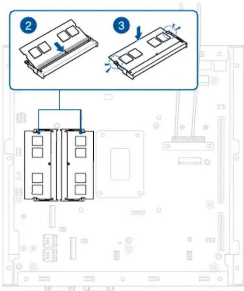
- Repeat steps 2-3 to install the other memory module.
3.6 Installing an M.2 SSD module to the M.2 M-key slot
Your Embedded Computer comes with an M.2 M-key slot that allows you to install an M.2 (M-key, supports 2280 PCIe Gen4 x4) SSD module.
To install an M.2 SSD module:
- Follow the steps in the Removing the heat spreader section to remove the bottom cover and heat spreader.
- Align and insert the M.2 SSD module into its slot inside the Embedded Computer.
- Gently push down the module on top of the standoff and fasten it using a screw.

3.7 Installing a wireless card to the M.2 E-key slot
Your Embedded Computer comes with an M.2 E-key slot that allows you to install an M.2 (E-key, Wi-Fi / Bluetooth) wireless module.
WARNING! RF modules are intended for OEM or host integrators only. For availability of system level RF certification, check with your OEM integrator.
To install an M.2 wireless module:
- Follow the steps in the Removing the heat spreader section to remove the bottom cover and heat spreader.
- Remove the screw from the M.2 standoff.
NOTE: We recommend using a PH1 screwdriver with a torque of 2.0 ± 0.2 kgf-cm when tightening the screw.
- Align and insert the wireless card into its slot inside the Embedded Computer.
- Gently push down the wireless card on top of the standoff, and then fasten it using the previously removed screw.
NOTE: We recommend using a PH1 screwdriver with a torque of 2.0 ± 0.2 kgf-cm when tightening the screw.
- (Optional) Connect the RF cables from the antennas to your wireless card. Make sure that the correct cable is attached to each of the connectors by referring to the illustration below.
NOTE:
- Please refer to the Installing antennas section for more information on installing the antennas.
- Connecting antennas to your wireless card may strengthen the wireless signal.
- A soft clicking sound indicates that the antenna has been securely attached on the wireless card.

3.8 Installing a cellular network module to the M.2 B-key slot
Your Embedded Computer comes with an M.2 B-key slot that allows you to install a B-key (PCIe x1/USB 3.2 Gen 1/USB2.0, type 3042/3052) M.2 device, such as a 4G LTE or 5G NR module.
WARNING! RF modules are intended for OEM or host integrators only. For availability of system level RF certification, check with your OEM integrator.
To install a 4G LTE module:
- Follow the steps in the Removing the heat spreader section to remove the bottom cover and heat spreader.
- Remove the screw from the M.2 standoff.
NOTE: We recommend using a PH1 screwdriver with a torque of 2.0 ± 0.2 kgf-cm when tightening the screw.
- If the standoff is already seated in the right mounting hole to fit your module, skip to step 5.
- Unscrew the standoff, and install it to a mounting hole that matches the length of your module.
NOTE: We recommend using a PH1/sleeve screwdriver with a torque of 2.0 ± 0.2 kgf-cm when tightening the standoff.
- Align and insert the module into the slot.
- Press down, and then secure it in place using the screw previously removed.
NOTE: We recommend using a PH1 screwdriver with a torque of 2.0 ± 0.2 kgf - cm when tightening the screw.
- (Optional) Connect the RF cables from the antennas to your module. Make sure that the correct cable is attached to each of the connectors by following the chart on the next page.
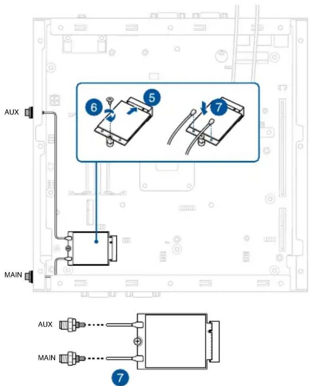
NOTE:
• Refer to Installing antennas for more information on installing the antennas. - Connecting antennas to your module may strengthen the signal. - A soft clicking sound indicates that the antenna has been securely attached to the module.
To install a 5G NR module:
WARNING! RF modules are intended for OEM or host integrators only. For availability of system level RF certification, check with your OEM integrator.
- Follow the steps in the Removing the heat spreader section to remove the bottom cover and heat spreader.
- Remove the screw from the M.2 standoff.
NOTE: We recommend using a PH1 screwdriver with a torque of 2.0 ± 0.2 kgf-cm when tightening the screw.
- If the standoff is already seated in the right mounting hole to fit your module, skip to step 5.
- Unscrew the standoff, and install it to a mounting hole that matches the length of your module.
NOTE: We recommend using a PH1/sleeve screwdriver with a torque of 2.0 ± 0.2 kgf-cm when tightening the standoff.
- Align and insert the module into the slot.
- Press down, and then secure it in place using the screw previously removed.
NOTE: We recommend using a PH1 screwdriver with a torque of 2.0 ± 0.2 kgf-cm when tightening the screw.
- (Optional) Connect the RF cables from the antennas to your module. Make sure that the correct cable is attached to each of the connectors by following chart on the next page.
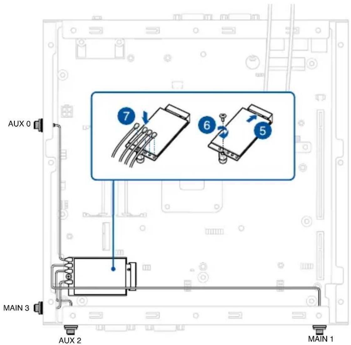
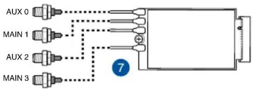
3.9 Installing an mPCIe module
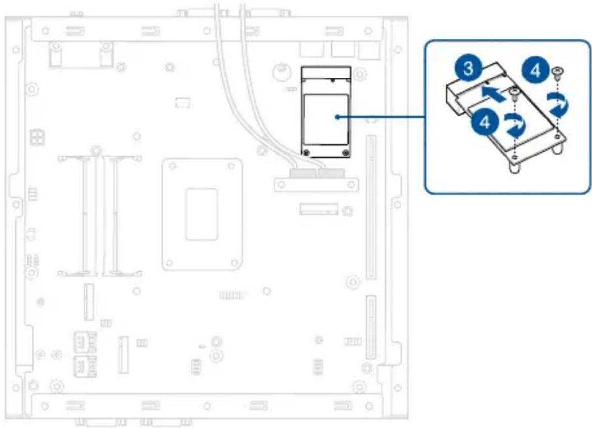
Your Embedded Computer comes with an mPCIe slot that allows you to install an mPCIe add-on module, such as a CANbus module.
To install an mPCIe module:
- Follow the steps in the Removing the heat spreader section to remove the bottom cover and heat spreader.
- Remove the two (2) screws from the standoffs.
- Align and insert the module into the slot.
- Press down, and then secure it in place using the two (2) screws previously removed.
NOTE: We recommend using a PH1 screwdriver with a torque of 2.0 ± 0.2 kgf-cm when tightening the screws.
- Connect the necessary cables based on the type of module installed.
3.10 Installing a nano SIM card
Your Embedded Computer comes with two (2) nano SIM card slots.
NOTE: Nano SIM cards are purchased separately.
To install a nano SIM card:
- Follow the steps in the Removing the heat spreader section to remove the bottom cover and heat spreader.
- (Optional) Remove the M.2 module from the M.2 B-key slot, if one is installed, by first removing the screw securing the module, and then removing the module.
- Push the nano SIM cover in the direction towards the M.2 B-key slot.
- Lift the nano SIM cover.
- Place the nano SIM into the nano SIM slot.
- Close the nano SIM cover.
- Push the nano SIM cover away from the M.2 B-key slot to secure the nano SIM card.
- Repeat steps 3 to 7 to install a second nano SIM card.

3.11 Installing a GPU card
NOTE: The maximum size GPU card that will fit in this Embedded Computer is 229 mm (L) x 123.24 mm (H) x 49.6 mm (W). If installing a GPU card that is longer than 200 mm, you will need to relocate the chassis fan.
- Remove the two (2) screws securing the PCIe protective cover to the front of your Embedded Computer, and remove the PCIe protective cover.
- Identify the punch-out port on the front of your Embedded Computer corresponding to the slot that will be occupied by the GPU card.
- Detach the metal cover of the punch-out port by repeatedly pushing the left and right edges of the cover into the chassis until it breaks loose.
WARNING! Take extra care when removing the metal cover. Use tools, such as a screw driver, to bend and detach the metal cover to avoid physical injury.
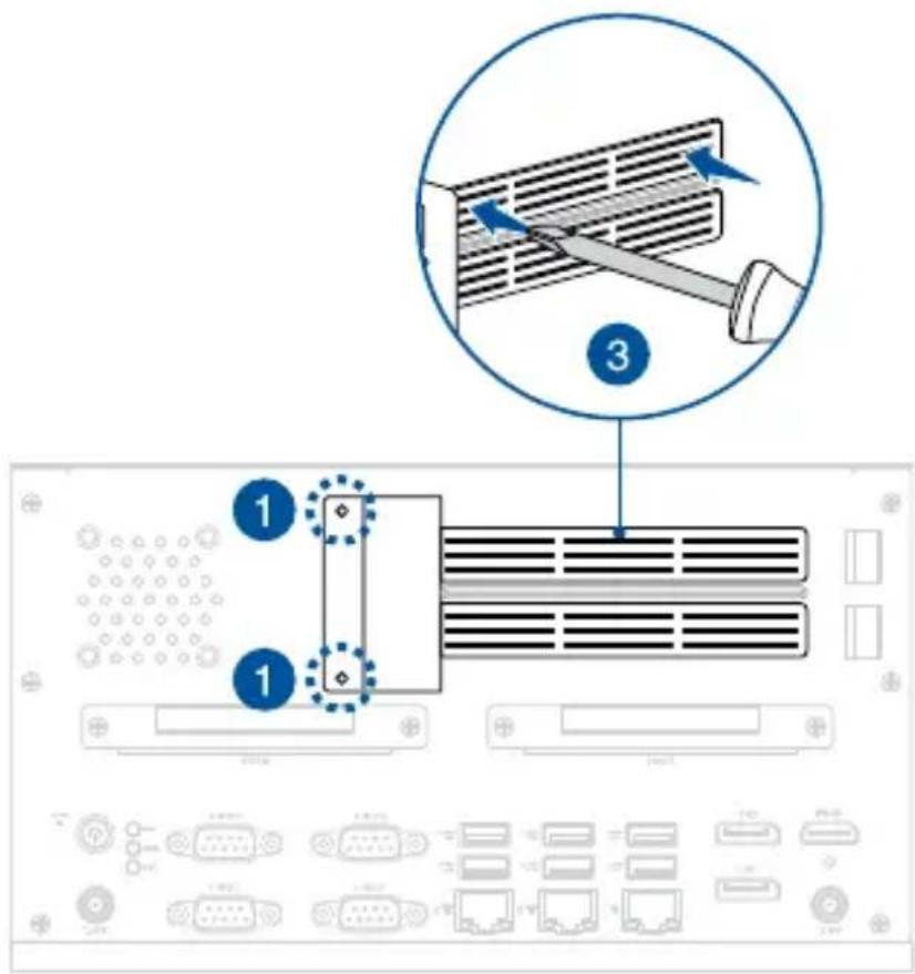
- (Optional) For GPU cards that are longer than 200 mm, you will need to relocate the chassis fan installed on the rear panel to prevent interference.
NOTE: Before moving the chassis fan, remove the metal covers from the fan mount area to enable sufficient air flow.

- Insert your GPU card to the empty PCIe slot corresponding to the punch-out port with the metal cover you removed earlier. Ensure that the tapered end of the retaining bracket is inserted into the recessed receptacle on the chassis.
- Secure the retaining bracket to the chassis using a screw.

- Connect the 4-pin end of an expansion card power cable to the EX_DCIN connector on the motherboard (A) and the other end to your GPU card (B).

3.12 Installing antennas (optional)
You may install antennas to the six (6) antenna jacks located on the front and right sides of your Embedded Computer. The installed antennas can be connected to the 4G LTE or 5G NR module installed in the M.2 B-key slot and to the wireless card installed in the M.2 E-key Wi-Fi slot.
NOTE: It is recommended that you refer to the illustration that corresponds to the module(s) you have installed in your Embedded Computer.
For 4G LTE module

For 5G NR module
For wireless card
To install an antenna:
NOTE: If your Embedded Computer came pre-installed with antenna jacks, skip to step 9.
- Remove the bottom cover. Refer to Removing the bottom cover for details.
- (Optional) To install the antennas on the front panel for 5G NR modules, you will also need to remove the front panel by removing the two (2) screws securing it to the chassis.
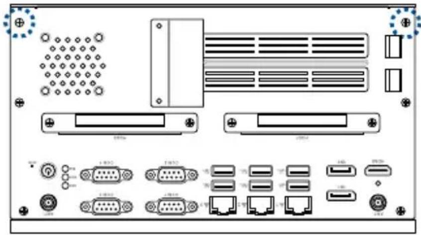
- Prepare the RF connector and cable.
- Remove the rubber caps from the antenna holes.
- Insert the antenna jack end of the RF connector and cable into the antenna jack from within the chassis outwards.
- Insert the bundled O-ring to the antenna jack.
- Secure the antenna jack using the bundled hex screw.
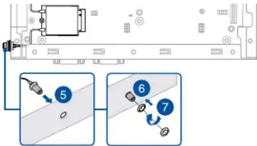
- (Optional) For RF cables that need to be connected to the front panel, route them to the 5G NR module through the two cutouts on the motherboard.

- Connect the other end of the RF connector and cable to your wireless card (refer to Installing a wireless card to the M.2 E-key slot for details) or to your cellular network module (refer to Installing a cellular network module to the M.2 B-key slot for details).
- Replace the bottom cover. Refer to Replacing the bottom cover for details.
- Screw the external wireless antennas onto their corresponding antenna jacks on your Embedded Computer by turning them in a clockwise direction.
- Position the antennas for optimal signal reception.
Watchdog Timer
4
4.1 Watchdog Timer implementation
The Watchdog Timer used in this Embedded Computer is the POST Watchdog Timer. The Watchdog Timer circuit is in SuperIO and can be controlled by the BIOS setup menu through the system BIOS for different boot phases.
Please refer to the table below for more details on the implementation of the Watchdog Timer.
| Watchdog timer Implementation Default Timeout | ||
| POST Watchdog Timer | This Watchdog Timer is for recovering the system from crashes during BIOS takeover to OS. | The timeout value is determined by the BIOS settings. |
| NOTE: The default setting for the BIOS item is set to enabled. | ||
| *OS Watchdog Timer | No implementation. User needs to write software in OS to keep updating the watchdog timer to prevent it from timing out. The application is executed on payload. | N/A |
| NOTE: Please refer to the section Watchdog Timer Programming for more information. | ||
4.2 Watchdog Timer programming
Please refer to the pseudo code for the NCT6116D watchdog timer programming below:
SIO_INDEX_PORT is 0x2E
SIO_DATA_PORT is 0x2F
1. Set WDT Time Unit
Outportb(SIO_INDEX_PORT, 0x87); // Unlock SIO
Outportb(SIO_INDEX_PORT, 0x87); // Unlock SIO
Outportb(SIO_INDEX_PORT, 0x07);
Outportb(SIO_DATA_PORT, 0x08);
Outportb(SIO_INDEX_PORT, 0xF0);
val = Inportb(SIO_DATA_PORT) // Read current WDT setting
val = val | 0x08; // minute mode, val = val & 0xF7 if second mode
Outportb(SIO_INDEX_PORT, 0xF0);
Outportb(SIO_DATA_PORT, val); // Write back WDT setting
Outportb(SIO_INDEX_PORT, 0xAA); // Lock SIO
2. Set WDT Time
Outportb(SIO_INDEX_PORT, 0x87); // Unlock SIO
Outportb(SIO_INDEX_PORT, 0x87); // Unlock SIO
Outportb(SIO_INDEX_PORT, 0x07);
Outportb(SIO_DATA_PORT, 0x08);
Outportb(SIO_INDEX_PORT, 0xF1);
Outportb(SIO_DATA_PORT, Time); // Write WDT time, value 1 to 255
Outportb(SIO_INDEX_PORT, 0xAA); // Lock SIO
3. Enable WDT
Outportb(SIO_INDEX_PORT, 0x87); // Unlock SIO
Outportb(SIO_INDEX_PORT, 0x87); // Unlock SIO

Outportb(SIO_INDEX_PORT, 0x07);
Outportb(SIO_DATA_PORT, 0x08);
Outportb(SIO_INDEX_PORT, 0x30);
val = Inportb(SIO_DATA_PORT) // Read current WDT status

val = val | 0x01; // Enable WDT Timer

Outportb(SIO_INDEX_PORT, 0x30);
Outportb(SIO_DATA_PORT, val); // Write back WDT status

Outportb(SIO_INDEX_PORT, 0xAA); // Lock SIO
4. Disable WDT
Outportb(SIO_INDEX_PORT, 0x87); // Unlock SIO
Outportb(SIO_INDEX_PORT, 0x87); // Unlock SIO
Outportb(SIO_INDEX_PORT, 0x07);
Outportb(SIO_DATA_PORT, 0x08);
Outportb(SIO_INDEX_PORT, 0xF1);
Outportb(SIO_DATA_PORT, 0x00); // Clear WDT time, it means WDT Time-Out disable
Outportb(SIO_INDEX_PORT, 0x30);
val = Inportb(SIO_DATA_PORT) // Read current WDT status
val = val & 0xFE; // Disable WDT Timer
Outportb(SIO_INDEX_PORT, 0x30);
Outportb(SIO_DATA_PORT, val); // Write back WDT status
Outportb(SIO_INDEX_PORT, 0xAA); // Lock SIO
Appendix
Safety information
Your Embedded Computer is designed and tested to meet the latest standards of safety for information technology equipment. However, to ensure your safety, it is important that you read the following safety instructions.
Setting up your system
- Read and follow all instructions in the documentation before you operate your system.
- Do not use this product near water or a heated source.
- Set up the system on a stable surface.
- Peripherals with extended tolerance (such as industrial grade memory and storage) will allow this product to be used in environments with ambient temperatures between -25°C and 60°C with adequate airflow.
- If you use an extension cord, make sure that the total ampere rating of the devices plugged into the extension cord does not exceed its ampere rating.
- This equipment should be installed and operated with a minimum distance of 20 cm between the radiator and your body.
- Restricted Access Area:
The equipment should only be installed in a Restricted Access Area where both these conditions apply:
- access can only be gained by skilled persons who have been instructed about the reasons for the restrictions applied to the area and about any precautions that shall be taken; and
- access is through the use of a TOOL or lock and key, or other means of security, and is controlled by the authority responsible for the area.
- This device shall not be connected to an Ethernet network with outside plant routing.
Care during use
- Do not walk on the power cord or allow anything to rest on it.
- Do not spill water or any other liquids on your system.
- When the system is turned off, a small amount of electrical current still flows. Always unplug the power cord from the power outlets before cleaning the system.
- Use this product with care when operating at full load, as the product, especially the outer casing, may reach elevated temperatures.
- If you encounter the following technical problems with the product, unplug the power cord and contact a qualified service technician or your retailer.
- The power cord or plug is damaged. – Liquid has been spilled into the system.
- The system does not function properly even if you follow the operating instructions.
- The system was dropped or the cabinet is damaged.
- The system performance changes.
Lithium-Ion Battery Warning
CAUTION: Danger of explosion if battery is incorrectly replaced. Replace only with the same or equivalent type recommended by the manufacturer. Dispose of used batteries according to the manufacturer's instructions.
NO DISASSEMBLY
The warranty does not apply to the products that have been disassembled by users

DO NOT throw the Embedded Computer in municipal waste. This product has been designed to enable proper reuse of parts and recycling. This symbol of the crossed out wheeled bin indicates that the product (electrical, electronic equipment, and mercury-containing button cell battery) should not be placed in municipal waste. Check local technical support services for product recycling.
Regulatory notices
FCC Compliance Information
Responsible Party: Asus Computer International
Address: 48720 Kato Rd., Fremont, CA 94538, USA
Phone / Fax No: (510)739-3777 / (510)608-4555
This device complies with Part 15 of the FCC Rules. Operation is subject to the following two conditions: (1) This device may not cause harmful interference, and (2) This device must accept any interference received, including interference that may cause undesired operation.
This equipment has been tested and found to comply with the limits for a Class A digital device, pursuant to part 15 of the FCC Rules. These limits are designed to provide reasonable protection against harmful interference when the equipment is operated in a commercial environment.
This equipment generates, uses, and can radiate radio frequency energy and, if not installed and used in accordance with the instruction manual, may cause harmful interference to radio communications. Operation of this equipment in a residential area is likely to cause harmful interference, in which case the user will be required to correct the interference at his own expense.
IMPORTANT! Outdoor operations in the 5.15~5.25 GHz band is prohibited. This device has no Ad-hoc capability for 5250~5350 and 5470~5725 MHz.
CAUTION! Any changes or modifications not expressly approved by the party responsible for compliance could void the user's authority to operate the equipment.
Compliance Statement of Innovation, Science and Economic Development Canada (ISED)
This device complies with Innovation, Science and Economic Development Canada licence-exempt RSS standard(s). Operation is subject to the following two conditions: (1) this device may not cause interference, and (2) this device must accept any interference, including interference that may cause undesired operation of the device.
CAN ICES-003(A)/NMB-003(A)
KC: Korea Warning Statement
Class A:
User's Guide
Accessories that came with this product have been designed and verified for use in connection with this product. Never use accessories for other products to prevent the risk of electric shock or fire.
Declaration of compliance for product environmental regulation
ASUS follows the green design concept to design and manufacture our products, and makes sure that each stage of the product life cycle of ASUS product is in line with global environmental regulations. In addition, ASUS disclose the relevant information based on regulation requirements.
Please refer to https://esg.asus.com/Compliance.htm for information disclosure based on regulation requirements ASUS is complied with.
EU REACH and Article 33
Complying with the REACH (Registration, Evaluation, Authorization, and Restriction of Chemicals) regulatory framework, we publish the chemical substances in our products at ASUS REACH website at https://esg.asus.com/Compliance.htm
EU RoHS
This product complies with the EU RoHS Directive. For more details, see https://esg.asus.com/Compliance.htm
Japan JIS-C-0950 Material Declarations
Information on Japan RoHS (JIS-C-0950) chemical disclosures is available on https://esg.asus.com/Compliance.htm
India RoHS
This product complies with the “India E-Waste (Management) Rules, 2016” and prohibits use of lead, mercury, hexavalent chromium, polybrominated biphenyls (PBBs) and polybrominated diphenyl ethers (PBDEs) in concentrations exceeding 0.1% by weight in homogenous materials and 0.01% by weight in homogenous materials for cadmium, except for the exemptions listed in Schedule II of the Rule.
Vietnam RoHS
ASUS products sold in Vietnam, on or after September 23, 2011, meet the requirements of the Vietnam Circular 30/2011/TT-BCT.
ASUS recycling and takeback programs come from our commitment to the highest standards for protecting our environment. We believe in providing solutions for you to be able to responsibly recycle our products, batteries, other components as well as the packaging materials. Please go to https://esg.asus.com/en/Takeback.htm for detailed recycling information in different regions.
Ecodesign Directive
The European Union announced a framework for the setting of ecodesign requirements for energy-related products (2009/125/EC).
Specific implementing measures are aimed at improving environmental performance of specific products or across multiple product types. ASUS provides product information at https://esg.asus.com/Compliance.htm.
China Compulsory Certification
Taiwan Declaration of Restricted Substances Marking
| 單元(Unit) | 限用物質及其化學符號(Restricted substances and its chemical symbols) | |||||
| 鉛Lead(Pb) | 汞Mercury(Hg) | 鎘Cadium(Cd) | 六價鉻Hexavalent chromium( Cr+6 ) | 多溴聯苯Polybrominated biphenyls(PBB) | 多溴二苯醚Polybrominated diphenyls ethers(PBDE) | |
| 印刷電路板及電子組件PCB | - ○ | ○ ○ ○ | ○ | |||
| 外殼Chassis | - ○ | ○ ○ ○ | ○ | |||
| 硬碟Disk drive | - ○ | ○ ○ ○ | ○ | |||
| 散熱設備Thermal solutions | - ○ | ○ ○ ○ | ○ | |||
| 其他及其配件(線材等)Accessories (e.g., cables) | - ○ | ○ ○ ○ | ○ | |||
| 備考1. “○”係指該項限用物質之百分比含量未超出百分比含量基準值。備考2. “-”係指該項限用物質為排除項目。Note 1 “○” indicates that the percentage content of the restricted substance does not exceed the percentage of reference value of presence.Note 2 The“—”indicates that the restricted substance corresponds to the exemption. | ||||||
UK: The Radio Equipment Regulations 2017 (S.I. 2017/1206)
Simplified UKCA Declaration of Conformity
ASUSTek Computer Inc. hereby declares that this device is in compliance with the essential requirements and other relevant provisions of The Radio Equipment Regulations 2017 (S.I. 2017/1206). Full text of UKCA declaration of conformity is available at https://www.asus.com/support/.
The WiFi operating in the band 5150-5350MHz shall be restricted to indoor use for country listed below:
UK
EU: Radio Equipment Directive (Directive 2014/53/EU)
Simplified EU Declaration of Conformity
ASUSTek Computer Inc. hereby declares that this device is in compliance with the essential requirements and other relevant provisions of Directive 2014/53/EU. Full text of EU declaration of conformity is available at https://www.asus.com/support/. The WiFi operating in the band 5150-5350MHz shall be restricted to indoor use for countries listed in the table below:
https://www.asus.com/support/
https://www.asus.com/support/
RF Module Warning Statement
RF modules are intended for OEM or host integrators only. For availability of system level RF certification, check with your OEM integrator.
Service and Support
Visit our multi-language website at https://www.asus.com/support/.



- LIMITATION OF LIABILITY
- SERVICE AND SUPPORT
- CONTENTS
- CHAPTER 1: GETTING TO KNOW YOUR EMBEDDED COMPUTER
- FEATURES
- MOTHERBOARD & RISER CARD OVERVIEW
- CHAPTER 2: USING YOUR EMBEDDED COMPUTER
- GETTING STARTED
- TURNING OFF YOUR EMBEDDED COMPUTER
- INSTALLING WALL MOUNT BRACKETS
- CHAPTER 3: UPGRADING YOUR EMBEDDED COMPUTER
- CHAPTER 4: WATCHDOG TIMER
- APPENDIX
- ABOUT THIS MANUAL
- CONVENTIONS USED IN THIS MANUAL
- PACKAGE CONTENTS
- OPTIONAL ITEM(S)
- NOTE
- GETTING TO KNOW YOUR EMBEDDED COMPUTER
- FRONT VIEW
- HDMI HDMI™ PORT WITH CABLE LOCK
- ANT. WIRELESS ANTENNA JACK
- D1 DUAL-MODE DISPLAYPORT
- G USB 1 USB 10GBPS PORT
- G LAN PORT
- LAN PORT LED INDICATIONS
- COM1 COM
- SERIAL (COM) CONNECTOR
- COM3 COM
- HDD DRIVE ACTIVITY LED
- WDT WATCHDOG LED
- IGN IGNITION LED
- POWER BUTTON
- HDD1 2.5-INCH HOT-SWAP STORAGE BAY
- EXPANSION CARD SLOT
- AIR VENTS
- RESET SYSTEM RESET PINHOLE
- REAR VIEW
- POWER INPUT
- REMOTE POWER CONNECTOR
- USB 5GBPS PORT
- USB 2.0 PORT
- MICROPHONE INPUT JACK
- FUNCTIONAL EARTH GROUND
- ISOLATED DIO CONNECTOR (OPTIONAL)
- SERIAL CONNECTOR (OPTIONAL)
- AUDIO OUTPUT JACK
- LEFT VIEW
- RIGHT VIEW
- MOTHERBOARD LAYOUT
- ONBOARD JUMPERS
- COM +5V/+12V SELECTION JUMPER
- CLEAR RTC RAM JUMPER
- INTERNAL CONNECTORS
- MINI PCIE SLOT
- RTC BATTERY CONNECTOR
- RISER CARD SLOT
- M.2 M-KEY SLOT
- SATA 6GB/S CONNECTOR
- CONNECTOR TYPE
- SPI TPM CONNECTOR
- M.2 B-KEY SLOT
- NANO SIM CARD SLOT
- M.2 E-KEY (WI-FI) SLOT
- COM DEBUG CONNECTOR
- PIN POWER CONNECTOR
- DIMM SLOT
- GPIO CONNECTOR
- I2C CONNECTOR
- RISER CARD LAYOUT
- RISER CARD CONNECTORS
- WARNING
- PCIE GEN4 X4 SLOT
- PCIE GEN4 X16 SLOT
- USING YOUR EMBEDDED COMPUTER
- CONNECT THE AC POWER ADAPTER TO YOUR EMBEDDED COMPUTER
- IMPORTANT
- CONNECT A DISPLAY PANEL TO YOUR EMBEDDED COMPUTER
- TO CONNECT A DISPLAY PANEL TO YOUR EMBEDDED COMPUTER
- CONNECT DISPLAY VIA DISPLAYPORT
- CONNECT THE USB CABLE FROM KEYBOARD OR MOUSE
- TO CONNECT A KEYBOARD AND MOUSE TO YOUR EMBEDDED COMPUTER
- TURN ON YOUR EMBEDDED COMPUTER
- UPGRADING YOUR EMBEDDED COMPUTER
- INSTALLING A STORAGE DEVICE
- REMOVING THE BOTTOM COVER
- REPLACING THE BOTTOM COVER
- REMOVING THE HEAT SPREADER
- INSTALLING MEMORY MODULES
- TO INSTALL A MEMORY MODULE
- INSTALLING AN M.2 SSD MODULE TO THE M.2 M-KEY SLOT
- TO INSTALL AN M.2 SSD MODULE
- INSTALLING A WIRELESS CARD TO THE M.2 E-KEY SLOT
- TO INSTALL AN M.2 WIRELESS MODULE
- INSTALLING A CELLULAR NETWORK MODULE TO THE M.2 B-KEY SLOT
- TO INSTALL A 4G LTE MODULE
- TO INSTALL A 5G NR MODULE
- INSTALLING AN MPCIE MODULE
- TO INSTALL AN MPCIE MODULE
- INSTALLING A NANO SIM CARD
- TO INSTALL A NANO SIM CARD
- INSTALLING A GPU CARD
- INSTALLING ANTENNAS (OPTIONAL)
- FOR 4G LTE MODULE
- TO INSTALL AN ANTENNA
- WATCHDOG TIMER
- WATCHDOG TIMER IMPLEMENTATION
- WATCHDOG TIMER PROGRAMMING
- SET WDT TIME UNIT
- SET WDT TIME
- ENABLE WDT
- DISABLE WDT
- SAFETY INFORMATION
- SETTING UP YOUR SYSTEM
- CARE DURING USE
- LITHIUM-ION BATTERY WARNING
- NO DISASSEMBLY
- THE WARRANTY DOES NOT APPLY TO THE PRODUCTS THAT HAVE BEEN DISASSEMBLED BY USERS
- REGULATORY NOTICES
- FCC COMPLIANCE INFORMATION
- COMPLIANCE STATEMENT OF INNOVATION, SCIENCE AND ECONOMIC DEVELOPMENT CANADA (ISED)
- KC: KOREA WARNING STATEMENT
- DECLARATION OF COMPLIANCE FOR PRODUCT ENVIRONMENTAL REGULATION
- EU REACH AND ARTICLE
- EU ROHS
- JAPAN JIS-C-0950 MATERIAL DECLARATIONS
- INDIA ROHS
- VIETNAM ROHS
- ECODESIGN DIRECTIVE
- CHINA COMPULSORY CERTIFICATION
- UK: THE RADIO EQUIPMENT REGULATIONS 2017 (S.I. 2017/1206)
- SIMPLIFIED UKCA DECLARATION OF CONFORMITY
- EU: RADIO EQUIPMENT DIRECTIVE (DIRECTIVE 2014/53/EU)
- SIMPLIFIED EU DECLARATION OF CONFORMITY
- RF MODULE WARNING STATEMENT
Brand : ASUS
Model : PE5101D
Category : Computer