
DM-600 - Flat Screen Mount Gabor - Free user manual and instructions
Find the device manual for free DM-600 Gabor in PDF.


| Product Type | Single Arm Monitor Mount |
| Brand | Gabor |
| Model | DM-600 |
| Compatible Screen Size | 17 to 45 in. (43.2 to 114.3 cm) |
| Maximum Load (Flat Monitor) | 2.2 to 35.2 lb (1 to 16 kg) |
| Maximum Load (Curved Monitor) | 2.2 to 28.6 lb (1 to 13 kg) |
| VESA Standards | 75×75, 100×100 mm |
| Mounting Options | Clamp (up to 3.1 in./80 mm) or Grommet (up to 1.6 in./40 mm) |
| Arm Type | Articulating arm with gas spring |
| Arm Height Adjustment | 8.5 to 19.9 in. (21.5 to 50.5 cm) |
| Maximum Reach | 21.1 in. (53.6 cm) |
| Tilt Range | ±90° (with adjustable tension) |
| Swivel Range (Base Arm) | ±180° or ±90° (selectable) |
| Swivel Range (Monitor Arm) | ±180° |
| Rotation Range | ±90° |
| Pivot Range | ±90° (with adjustable tension) |
| Cable Management | Yes, with upper, lower, and rear cable guides |
| Gas Spring Tension Adjustment | Yes, adjustable for optimal balance |
| Material | Steel and Aluminum (estimated) |
| Weight (Mount Only) | 7.4 lb (3.4 kg) |
| Warranty | One-year limited warranty |
| Recommended Surface | Sturdy, flat desktop; not for weak or uneven surfaces |
| Color | Black (estimated) |
Frequently Asked Questions - DM-600 Gabor
User questions about DM-600 Gabor
0 question about this device. Answer the ones you know or ask your own.
Ask a new question about this device
Download the instructions for your Flat Screen Mount in PDF format for free! Find your manual DM-600 - Gabor and take your electronic device back in hand. On this page are published all the documents necessary for the use of your device. DM-600 by Gabor.
USER MANUAL DM-600 Gabor
for 17-45 in. Desktop Computer Monitors
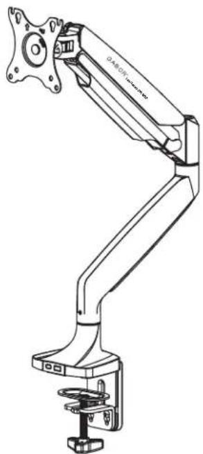
natural_image
Technical line drawing of a mechanical arm with articulated joints and mounting base (no text or symbols)User Manual
Thank you for choosing Gabor.
The Gabor Levitouch Single Arm Monitor Mount is designed to hold a 17 to 45 in. flat or curved monitor and offers multiple adjustments for the perfect viewing angle. Mount onto a desk or tabletop with the clamp or grammet attachments and preserve desk space while you're gaming, editing video, or watching a movie. The articulating arm has adjustable gas-spring tension ensuring stability when changing the monitor's height, tilt, and orientation.
Safety Warnings
- Please read and follow the instructions, and keep this manual in a safe place.
- When installing this product, be sure to refer to the mounting instructions detailed in this manual; failure to follow the mounting instructions may void the product warranty.
- Do not use this product for uses other than what it is intended for; the exact specifications, size parameters, and weight limits are found both on the product box and in the instruction manual.
- Clean this product with only a soft, dry cloth.
• Make sure this product is intact and there are no missing parts.
• Gabor takes no responsibility for any product damage or personal injury resulting from mishandling, incorrect mounting, faulty assembly, or improper use of this product.
- Mounting surfaces should be sturdy and flat. Do not install this product on a weak, uneven surface.
- Do not mount the device on structures that may be affected by vibrations or noticeable impacts; do not install near a heater, fireplace, or any other source of direct heat energy.
- This product may contain small parts which can pose a choking hazard: keep out of reach of children and pets.
- If you have safety concerns about installing this product, contact a qualified professional or installation contractor.
- If this product is missing hardware or there are defective ports, visit www.modebygabor.com or call Customer Service at 212 594-2353.
- All images are for illustrative purposes only.
Product Specifications
Monitor Display Size
17 to 45 in. (43.2 to 114.3 cm)
Maximum Load
Flat: 2.2 to 35.2 lb. (1 to 16 kg)
Curved: 2.2 to 28.6 lb. (1 to 13 kg)
Base Arm Swivel
±°180/±90°
Monitor Tilt/Pivot/Rotation
±90°/±90°/±180°
Monitor Arm Swivel
±180°
Arm Height Adjustment
8.5 to 19.9 in. (21.5 to 50.5 cm)
Maximum Reach
21.1 in. (53.6 cm)
Maximum Desktop Thickness
Clamp: 3.1 in. (80 mm)
Grommet: 1.6 in. (40 mm)
VESA Standards
75×75
100×100
Weight (without monitor)
7.4 lb. (3.4 kg)

Overview

natural_image
Technical line drawing of a mechanical component labeled A and 1X (no text or symbols on the diagram itself)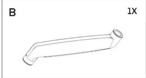
natural_image
Line drawing of a mechanical component labeled 'B' and '1X', showing a curved, elongated shape with a circular end (no text or symbols on the object itself)
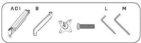
C 1X | D 1X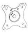 | E 1X | F 1X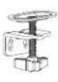 | G 1X | H 4X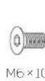 |
| I 1XM8×30M4×12D54×70mm5×80mm6×120mm | J 4X | K 4X | L 1X | M 1X | N 1X |
Clamp Installation
Step 1
Attach the brace to the base.

natural_image
Technical diagram of a mechanical assembly with mounting holes and a lever (no text or symbols)Step 2
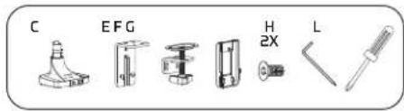
Loosen the two attached screws on the brace.

Step 3
Loosen the clamp.

natural_image
Mechanical assembly diagram showing a spring-loaded component with directional arrows indicating motion (no text or symbols)Clamp Installation (cont)
To secure the clamp to a surface 0.4 to 1.8 in. (10 to 45 mm) thick, follow these steps.

natural_image
Technical line drawing of a mechanical device with no visible text or symbolsAttach the clamp adopter to the brace and tighten the screws.

natural_image
Mechanical assembly diagram showing a rotating component with a bracket and housing (no text or symbols)Important! Make sure the back edge of the clamp is flush against the mounting surface. Attach the cable management adopter.
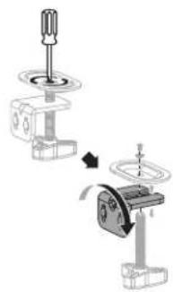
To secure the clamp to a surface 1.8 to 3.15 in. thick, (45 to 80 mm) follow these steps.
natural_image
Mechanical assembly diagram showing a screwdriver and a motor with rotating components (no text or symbols)Flip the clamp adapter by removing the clamp plate as shown above.

natural_image
Technical line drawing of a mechanical device with no visible text or symbolsAttach the clamp adapter to the brace and tighten the screws.

natural_image
Mechanical assembly diagram showing a rotating component and a rectangular housing (no text or symbols)Important! Make sure the back edge of the clamp is flush against the mounting surface.
Attach the cable management adapter.
Grommet Installation
Important! Predrilled holes
should be between 0.4 and 2.4 in.
(10 and 60 mm) wide.
Step 1
Attach the grommet to a surface up to 1.6 in. (40 mm) thick.
With Existing Through-Hole

Step 2
Unthread the clamp knob from the adapter.

natural_image
Mechanical assembly diagram showing a screw being inserted into a housing, with no visible text or symbolsStep 3
Thread the clamp knob through the clamp plate.

natural_image
3D mechanical assembly diagram showing a threaded component mounted on a flanged base (no text or symbols)Step 4
Thread the clamp knob through the surface's hole and into the base.

natural_image
Mechanical assembly diagram showing a clamping mechanism with rotating base and mounting base (no text or symbols)Arm Installation
Step 1
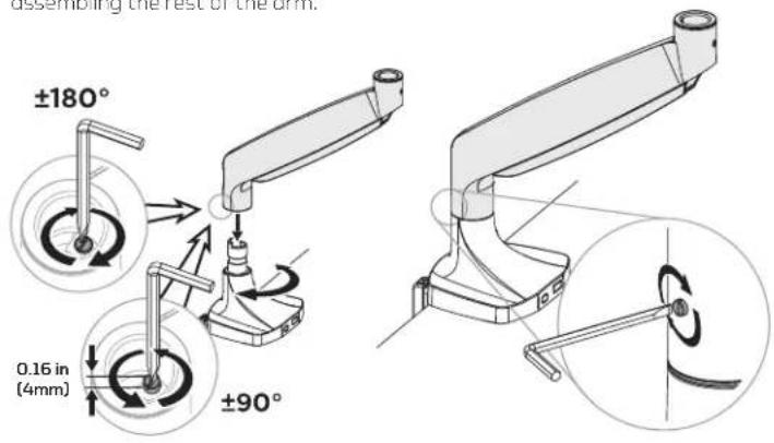
The arm rotates ±180^ (default) or ±90^ . Set the rotation degrees before assembling the rest of the arm.
Step 2
Tighten the arm's setscrew to secure it to the base.
Step 3
Seat the top arm in the bottom arm, and tighten the top arm's setscrew.

natural_image
Mechanical assembly diagram showing a lever mechanism with a magnified inset illustrating the motion of a rotating component (no text or symbols present)Step 4
Attach the monitor mount to the upper arm.

natural_image
Technical illustration showing two mechanical assembly steps: one with a hand holding a bracket, the other with a tool inserted into a component (no text or symbols present)Attaching a Monitor to the VESA Plate


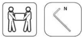
Important! For large and heavy monitors, it's recommended that two people hang the monitor.


natural_image
Technical diagram showing mechanical assembly with rotating components and a close-up of a tool inside a box (no text or symbols)
Balancing the Arm
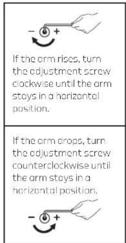
When the arm is adjusted to the ideal tension, it will hold the monitor in position indefinitely.
Support the monitor with one hand and position the arm and monitor so the arm is horizontal.

Important! To avoid damage to the monitors or mount, always keep the crm in a horizontal position while making adjustments, and do not overtighten the screws.

Adjusting the Monitor Orientation Cable Organization
Pivot
There are three pivots which provide ±90^ of rotation and offer adjustable tension.

natural_image
Diagram showing a hand interacting with a monitor and a mechanical clamp (no text or symbols)
Tilt
The monitor can tilt ±90° and offers adjustable tension.


natural_image
Line drawing of a person using a tool to adjust or install a component on a screen (no text or symbols visible)
Rotation
The monitor can rotate ±90° for horizontal and vertical orientation.
natural_image
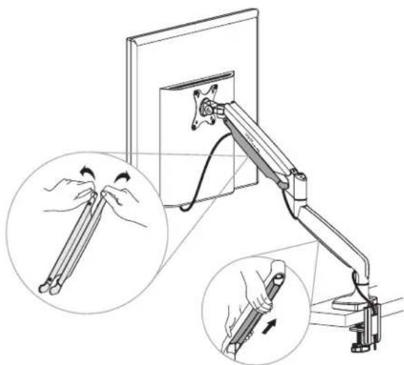
Illustration of a computer monitor with adjustable arm and two hand gestures, showing motion directions (no text or symbols)Run the monitor cables through the upper, lower, and rear cable guides for a clean and uncluttered desk.
One-Year Limited Warranty
This Gabor product is warranted to the original purchaser to be free from defects in materials and workmanship under normal consumer use for a period of one (1) year from the original purchase date or thirty (30) days after replacement, whichever occurs later. The warranty provider's responsibility with respect to this limited warranty shall be limited solely to repair or replacement, at the provider's discretion, of any product that fails during normal use of this product in its intended manner and in its intended environment. Inoperability of the product or part(s) shall be determined by the warranty provider. If the product has been discontinued, the warranty provider reserves the right to replace it with a model of equivalent quality and function.
This warranty does not cover damage or defect caused by misuse, neglect, accident, alteration, abuse, improper installation or maintenance. EXCEPT AS PROVIDED HEREIN, THE WARRANTY PROVIDER MAKES NEITHER ANY EXPRESS WARRANTIES NOR ANY IMPLIED WARRANTIES, INCLUDING BUT NOT LIMITED TO ANY IMPLIED WARRANTY OF MERCHANTABILITY OR FITNESS FOR A PARTICULAR PURPOSE. This warranty provides you with specific legal rights, and you may also have additional rights that vary from state to state.
To obtain warranty coverage, contact the Gabor Customer Service Department to obtain a return merchandise authorization ("RMA") number, and return the defective product to Gabor along with the RMA number and proof of purchase. Shipment of the defective product is at the purchaser's own risk and expense.
For more information or to arrange service, visit www.madebygabor.com or call Customer Service at 212-594-2353.
Product warranty provided by the Grodus Group.
www.grodusgroup.com
Cabor is a registered trademark of the Gradus Group. © 2024 Gradus Group LLC. All Rights Reserved.

GABOR®
A Gradus Group Brand
- Thank you for choosing Gabor.
- Safety Warnings
- Product Specifications
- Overview
- Clamp Installation
- Clamp Installation (cont)
- Grommet Installation
- Step 1
- Step 2
- Step 3
- Step 4
- Arm Installation
- Attaching a Monitor to the VESA Plate
- Balancing the Arm
- Adjusting the Monitor Orientation Cable Organization
- Pivot
- Tilt
- Rotation
- One-Year Limited Warranty
Brand : Gabor
Model : DM-600
Category : Flat Screen Mount