
CX153P4MWM - Microwave Accessories Café - Free user manual and instructions
Find the device manual for free CX153P4MWM Café in PDF.


| Product Type | Microwave Oven Built-In Trim Kit |
| Model Number | CX153P4MWM |
| Brand | Café |
| Compatible Microwave Model | CEB515 |
| Trim Kit Width Options | 27" and 30" |
| Cutout Height | 19 1/8" (486 mm) |
| Cutout Width (27" Model) | 26 7/8" (683 mm) |
| Cutout Width (30" Model) | 29 3/4" (756 mm) |
| Minimum Depth (Receptacle Outside Cutout) | 22" (559 mm) |
| Minimum Depth (Receptacle Inside Cutout) | 23 1/2" (597 mm) |
| Power Rating | 120 V AC, 60 Hz, 14 A, 1.60 kW |
| Grounding | 3-prong grounded plug required |
| Installation Height | Minimum 36" (914 mm) from floor to bottom of trim kit |
| Clearance for Air Flow | 1" (25 mm) beyond edge of trim kit frame |
| Parts Included | Rear Duct, Bottom Duct, Trim Kit Frame, 2 Rails, 19 Short Screws, 6 Long Wood Screws |
| Recommended Skill Level | Basic mechanical and electrical skills |
| Installation Time | 1 to 3 hours |
| Number of Installers Recommended | 2 people |
| Weight Capacity of Base | Minimum 100 lbs (45 kg) |
| Materials | Metal (steel) and plastic components |
| Maintenance | Clean with a damp cloth; avoid abrasive cleaners |
| Warranty | Installation issues not covered under warranty |
Frequently Asked Questions - CX153P4MWM Café
User questions about CX153P4MWM Café
0 question about this device. Answer the ones you know or ask your own.
Ask a new question about this device
Download the instructions for your Microwave Accessories in PDF format for free! Find your manual CX153P4MWM - Café and take your electronic device back in hand. On this page are published all the documents necessary for the use of your device. CX153P4MWM by Café.
USER MANUAL CX153P4MWM Café
Installation Instructions
Microwave Oven Built-In Trim Kits
CX152, CX153
If you have questions, visit our website at: cafeappliances.com
BEFORE YOU BEGIN
Read these instructions completely and carefully.
- IMPORTANT — Save these instructions for local inspector's use.
- IMPORTANT — Observe all governing codes and ordinances.
- Note to Installer – Be sure to leave these instructions with the Consumer.
- Note to Consumer – Keep these instructions for future reference.
- Skill level – Installation of this appliance requires basic mechanical and electrical skills.
• Completion time – 1 to 3 hours - Proper installation is the responsibility of the installer.
- Product failure due to improper installation is not covered under the Warranty.
• This kit is for use on model: CEB515 - This kit and microwave are approved for installation alone or above any single electric wall oven. Do not mount adjacent (within 2 feet) to any range, cooktop, gas oven, or other microwave.
- This product is to be installed 3 feet above floor level.
- Do not alter or modify any part of this kit or the oven.
- For easier installation and personal safety, we recommend that two people install this microwave oven.
- Unplug the microwave oven before attempting installation of this kit.
WARNING
This oven must be plugged into a
properly grounded 3-hole, 120 volt receptacle as required by the National Electrical Code.
▲WARNING
Before beginning the installation,
switch power off at service panel and lock the service disconnecting means to prevent power from being switched on accidentally. When the service disconnecting means cannot be locked, securely fasten a prominent warning device, such as a tag, to the service panel.
PARTS INCLUDED
| PART QUANTITY | ||
 | Rear Duct 1 | |
 | Bottom Duct | 1 |
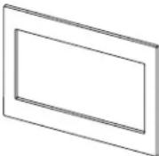 | Trim Kit Frame | 1 |
 | Rail | 2 |
 | Short Screws | 16 required 3 extra |
 | Long Wood Screws 4 required 2 extra | |
NOTE: This kit has extra screws to prevent the technician from spending extra time locating a replacement in case they lose one during installation.
GROUNDING INSTRUCTIONS
This appliance must be grounded. In the event of an electrical short circuit, grounding reduces the risk of electric shock by providing an escape wire for the electric current. This appliance is equipped with a cord having a grounding wire with a grounding plug. The plug must be plugged into an outlet that is properly installed and grounded. Consult a qualified electrician or serviceman if the grounding instructions are not completely understood, or if doubt exists as to whether the appliance is properly grounded.
WARNING
Improper use of the grounding plug can result in a risk of electric shock. Do not use an extension cord. If the power supply cord is too short, have a qualified electrician or serviceman install an outlet near the appliance
Permanent and Correct Installation

ELECTRICAL REQUIREMENTS
Product rating is 120 volts AC, 60 Hertz, 14 amps and 1.60 kilowatts. This product must be connected to a supply circuit of the proper voltage and frequency. Wire size must conform to the requirements of the National Electrical Code or the prevailing local code for this kilowatt rating. The power supply cord and plug should be brought to a separate 15 to 20 ampere branch circuit single grounded outlet. The outlet box should be located in the cabinet above the oven. The outlet box and supply circuit should be installed by a qualified electrician and conform to the National Electrical Code or the prevailing local code.
TOOLS YOU WILL NEED

CUTOUT DIMENSIONS
| Dimen-sion | Trim Kit | Cutout | |
| 27" 30" | |||
| Height 19 | 1/8" 19 | 1/8" 17 | 1/8 ± 1/8" |
| Width 26 | 7/8" 29 | 3/4" 23 | 1/4 ± 1/8" |
Min. depth with receptacle outside cutout – 22 " Min. depth with receptacle inside cutout – 23 1/2 " 120 volt – 60 Hertz grounded power receptacle.
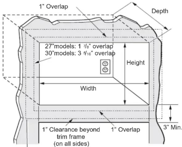
Bottom of trim kit must be minimum of 36" from floor
WARNING
This trim kit uses air flow from the top, bottom and sides of the trim frame. Blocking the air flow can cause the microwave to function improperly and may cause damage to the microwave.
Allow a 1" clearance beyond the edge of the trim kit frame to provide proper air flow.
FOR INSTALLATION ABOVE A BUILT-IN OVEN:
Microwave oven should be installed on a 3/8" plywood base and supported by 2x4 or 1x2 equivalent runners on all sides. Base must be capable of supporting a minimum of 100 lbs.
1 LOCATE AND INSTALL THE BASE PAN
Set Base Pan into the front cabinet microwave oven cutout and center it right and left. Push back until the front flange is against the cabinet front wall.
Mount the Base Pan using 3 short screws.

2 INSTALL THE RAILS
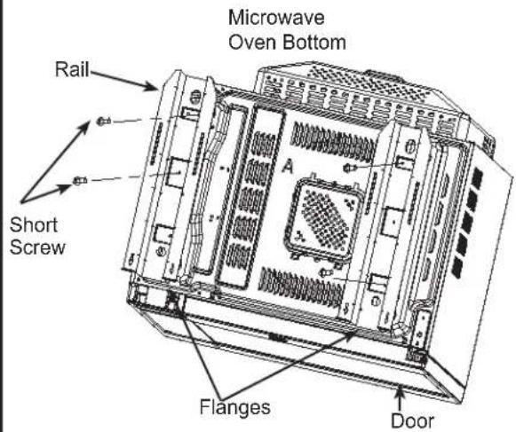
Disconnect the microwave oven from the receptacle. Remove everything out of the microwave oven, including packing, Owner's Manuals, turntable and turntable support. A protective film has been applied to some microwave oven and trim kits. If applied, remove the film. Turn over the microwave oven and secure the rails to oven Base Plate by inserting 4 short screws. Be careful not to scratch the microwave oven.
3 INSTALL THE REAR DUCT
- Gently return microwave oven to its upright position.
- Remove screw A.
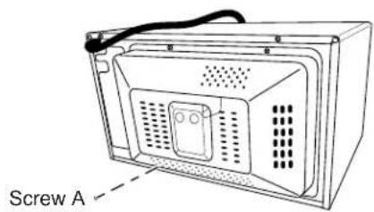
- Align the rear duct with the back of microwave oven, as shown.

- Slide 2 tabs into the slots on the right side of the back of microwave oven.

A. Rear duct tabs
B. Slots
- Use 2 short screws to secure top of rear duct to the back of microwave oven, as shown.

A. Short screws (2)
B. Rear duct
C. Back of microwave oven
3 INSTALL THE REAR DUCT (continued)
- Use 3 short screws to secure back of rear duct to the back of microwave oven, as shown.

A. Short screws (3)
B. Rear duct
C. Back of microwave oven
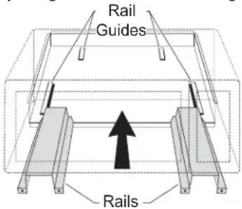
Plug the power cord into the wall receptacle. Slide the microwave oven assembly gently into the cabinet, using care not to pinch the power cord. Be sure to keep the assembly centered as it slides back to where the tongue of the rails goes through the slots on Base Plan. The top edges of the Base Plan should now be centered right to left in the opening. The Base should be tight against the cabinet.
5 CHECK LEVELING
Check the leveling by placing a level at the front and sides of the microwave. It may be necessary to add wood shims under the base pan to level the microwave front-to-back and side-to-side.
6 SECURE THE RAILS TO THE CABINET
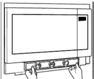
Ensure the Base Pan and Bottom Bracket front flanges are tight against the cabinet, and that the screws holes are aligned. Drive 4 short screws through the Base Pan and Rails into the cabinet

7 INSTALL THE TRIM KIT FRAME
- Position the assembled Trim Kit frame around the oven.
- Drill pilot holes using the drill (3/22).
- Secure the Trim Kit by 4 long screws through the trim kit into the cabinet by using a manual screw driver.
IMPORTANT-
— Start all screws before tightening any one screw. Do not overtighten screws since it can cause misalignment of top/side strips.

8 REPLACE ANY LOOSE ITEMS
- Your trim kit is now fully installed. Replace the turntable and turntable support that was removed from inside the microwave oven.
- Keep these installation instructions and extra screws for future reference and need. Do not place them in the microwave oven.
- Replace the house fuse, or close the circuit breaker to restore power at the service panel.
READ CAREFULLY. KEEP THESE INSTRUCTIONS.
6 ASEGURE LOS RIELES AL GABINETE
- INSTALLATION INSTRUCTIONS
- MICROWAVE OVEN BUILT-IN TRIM KITS
- BEFORE YOU BEGIN
- WARNING
- ▲WARNING
- GROUNDING INSTRUCTIONS
- ELECTRICAL REQUIREMENTS
- 1 LOCATE AND INSTALL THE BASE PAN
- 2 INSTALL THE RAILS
- 3 INSTALL THE REAR DUCT
- 3 INSTALL THE REAR DUCT (CONTINUED)
- 5 CHECK LEVELING
- 6 SECURE THE RAILS TO THE CABINET
- 7 INSTALL THE TRIM KIT FRAME
- IMPORTANT
- 8 REPLACE ANY LOOSE ITEMS
- READ CAREFULLY. KEEP THESE INSTRUCTIONS
- 6 ASEGURE LOS RIELES AL GABINETE
Brand : Café
Model : CX153P4MWM
Category : Microwave Accessories