
AHW0621CR1W - Air conditioner HISENSE - Free user manual and instructions
Find the device manual for free AHW0621CR1W HISENSE in PDF.


| Product Type | Window Air Conditioner |
| Model Number | AHW0621CR1W |
| Cooling Capacity | 6,000 BTU |
| Power Supply | 115 V, 60 Hz, 10 A |
| Refrigerant Type | R32 (Flammable) |
| Control Type | Electronic with Remote Control |
| Remote Control | Yes, with 23 ft (7 m) range |
| Display | LED with temperature and mode indicators |
| Fan Speeds | High, Med, Low |
| Operating Modes | Cool, Dry, Fan, Eco |
| Timer | 24-hour on/off timer |
| Sleep Mode | Yes, 8-hour automatic shut-off |
| Air Filter | Washable, clean every 2 weeks |
| Filter Alert | Indicator light for filter cleaning |
| Wi-Fi Connectivity | ConnectLife App compatible (2.4 GHz) |
| Air Direction | Vertical and horizontal adjustable louvers |
| Installation Type | Double-hung window, sliding window |
| Minimum Window Width | 22 inches (559 mm) |
| Minimum Window Height | 12 2/5 inches (315 mm) |
| Unit Dimensions (approx.) | 18 x 12 x 20 inches (WxHxD) |
| Weight (approx.) | 50 lbs (22.7 kg) |
| Power Cord | 3-prong grounded, with test/reset button |
| Safety Features | Ground prong, leak detection, R32 safety |
| Included Accessories | Remote control, side curtains, top rail, foam seals, screws |
Frequently Asked Questions - AHW0621CR1W HISENSE
User questions about AHW0621CR1W HISENSE
0 question about this device. Answer the ones you know or ask your own.
Ask a new question about this device
Download the instructions for your Air conditioner in PDF format for free! Find your manual AHW0621CR1W - HISENSE and take your electronic device back in hand. On this page are published all the documents necessary for the use of your device. AHW0621CR1W by HISENSE.
USER MANUAL AHW0621CR1W HISENSE
For questions about features, operation/ performance, parts or service, call: 1-877-465-3566
Important Safety Instructions .... 3
Disposing of the Unit 3
Pre-Installation....7
Electrical requirements 7
Recommended Grounding Method 7
Wiring requirement 7
Power Supply Cord 8
Planning Installation 8
Hardware Included....9
Unpack the Air Conditioner ....10
Location Requirements 10
Window Opening Measurements....12
If AC is Blocked by Storm Window....12
Installation 13
Operation.... 16
Air conditioner Use 16
Using the Remote Control 18
Changing Air Direction.... 20
Exhaust Air Vent 21
Normal Sounds 21
Using the ConnectLife APP 22
Care and Cleaning 23
Cleaning the Air Filter 23
Cleaning the Front Panel 23
Repairing Paint Damage 23
Annual Maintenance 23
Removing AC From Window. 23
Troubleshooting 24
Circuit diagram 26
Safety Information
We have provided many important safety messages in this manual and on your appliance. Always read and obey all safety messages.

DANGER: This symbol alerts you to a potential hazard, that if not avoided, will result in death or serious injury.

WARNING: This symbol alerts you to a potential hazard, that if not avoided, could result in death or serious Injury.

CAUTION: This symbol alerts you to a potential hazard, that if not avoided, may result in minor or moderate injury.

WARNING: Risk of Fire or Explosion. This unit contains flammable refrigerant.
Additional safety precautions must be followed.
☐ Do not use means to accelerate the defrosting process or to clean, other than those recommended by the manufacturer.
☐ The appliance shall be stored in a room without continuously operating ignition sources (for example: open flames, an operating gas appliance or an operating electric heater).
☐ Do not pierce or burn refrigerant tubing. Be aware that refrigerants may not contain an odor.
□ Compliance with national gas regulations shall be observed.
□ Keep ventilation openings clear of obstruction.
☐ The maximum refrigerant charge amount is shown on nameplate on the air conditioner.
☐ When handling, installing, and operating the appliance, care should be taken to avoid damage to the refrigerant tubing.
☐ Do not drill holes in the unit.
□ Maintenance, cleaning, and service should only be performed by technicians properly trained and qualified in the use of flammable refrigerants.
☐ Dispose of air conditioner in accordance with Federal and Local Regulations. Flammable refrigerants require special disposal procedures. Contact your local authorities for the environmentally safe disposal of your air conditioner.
☐ The appliance shall be stored so as to prevent mechanical damage from occurring.
☐ The appliance shall be stored in a well-ventilated area where the room size corresponds to the room area as specified for operation.
☐ This product contains small parts such as (batteries, battery cover and screws) that may cause suffocation if swallowed by children.
☐ For appliances with SUPPLEMENTARY HEATERS, the minimum clearance from the appliance to combustible surfaces is 50 cm.
Explanation of symbols displayed on the unit.
 A2L A2L | WARNING | This symbol shows that this appliance uses a flammable refrigerant. If the refrigerant is leaked and exposed to an external ignition source, there is a risk of fire. |
 | CAUTION | This symbol shows that the operation manual should be read carefully. |
 | CAUTION | This symbol shows that a service personnel should be handling this equipment with reference to the installation manual. |
 | CAUTION | This symbol shows that information is available such as the operating manual or installation manual. |
IMPORTANT SAFETY INSTRUCTIONS
To reduce the risk of fire, electrical shock or injury when using your air conditioner, follow these basic precautions:
□ Plug into a grounded 3-prong outlet.
☐ Do not remove ground prong.
□ Do not use an adapter.
☐ Do not use an extension cord.
□ Unplug air conditioner before servicing.
□ Use two or more people to move and install air conditioner.
☐If the SUPPLY CORD is damaged, it must be replaced by the manufacturer, its service agent or similarly qualified persons in order to avoid a hazard.
DISPOSING OF THE UNIT
☐ Before throwing out the device, it is necessary to remove the battery cells and dispose or recycle them properly.
☐ When you need disposal of the unit consult our dealer. If pipes are removed incorrectly, refrigerant may blow out and come into contact with your skin, causing injury. Releasing refrigerant into the atmosphere also damages the environments.
☐ Please recycle or dispose of the product packaging material in an environmentally responsible manner.
☐ Never store or ship the air conditioner upside down or sideways to avoid damage to the compressor.
☐ This appliance is not intended for use by persons (including children) with reduced physical, sensory or mental capabilities, or lack of experience and knowledge, unless they have been given supervision or instruction concerning use of the appliance by a person responsible for their safety. Children should be supervised to ensure that they do not play with the appliance.
☐ The wiring diagram is shown on nameplate on the air conditioner.

Safety Information (continued)
Precautions for using R32 refrigerant
The basic installation work procedures are the same as the conventional refrigerant (R22 or R410A). However, pay attention to the following :
- Transport of equipment containing flammable refrigerants
□ Compliance with the transport regulations. - Marking of equipment using signs
□ Compliance with local regulations. - Disposal of equipment using flammable refrigerants
□ Compliance with national regulations. - Storage of equipment/appliances
☐ The storage of equipment should be in accordance with the manufacturer's instructions.
5. Storage of packed (unsold) equipment
☐ Storage package protection should be constructed such that mechanical damage to the equipment inside the package will not cause a leak of the refrigerant charge.
☐ The maximum number of pieces of equipment permitted to be stored together will be determined by local regulations.
6. Information on servicing
☐ Checks to the area: Prior to beginning work on systems containing flammable refrigerants, safety checks are necessary to ensure that the risk of ignition is minimised. For repair to the refrigerating system, the following precautions shall be complied with prior to conducting work on the system.
☐ Work procedure: Work shall be undertaken under a controlled procedure so as to minimise the risk of flammable gas or vapour being present while the work is being performed.
☐ General work area: All maintenance staff and others working in the local area shall be instructed on the nature of work being carried out. Work in confined spaces shall be avoided. The area around the workspace shall be sectioned off. Ensure that the conditions within the area have been made safe by control of flammable material.
☐ Checking for presence of refrigerant: The area shall be checked with an appropriate refrigerant detector prior to and during work, to ensure the technician is aware of potentially flammable atmospheres. Ensure that the leak detection equipment being used is suitable for use with flammable refrigerants, i.e. non-sparking, adequately sealed or intrinsically safe.
☐ Presence of fire extinguisher: If any hot work is to be conducted on the refrigeration equipment or any associated parts, appropriate fire extinguishing equipment shall be available to hand. Have a dry powder or CO2 fire extinguisher adjacent to the charging area.
☐ No ignition sources: No person carrying out work in relation to a refrigeration system which involves exposing any pipe work that contains or has contained flammable refrigerant shall use any sources of ignition in such a manner that it may lead to the risk of fire or explosion. All possible ignition sources, including cigarette smoking, should be kept sufficiently far away from the site of installation, repairing, removing anddisposal, during which flammable refrigerant can possibly be released to the surrounding space. Prior to work taking place, the area around the equipment is to be surveyed to make sure that there are no flammable hazards or ignition risks. "No Smoking" signs shall be displayed.
□ Ventilated area: Ensure that the area is in the open or that it is adequately ventilated before breaking into the system or conducting any hot work. A degree of ventilation shall continue during the period that the work is carried out. The ventilation should safely disperse any released refrigerant and preferably expel it externally into the atmosphere.
☐ Checks to the refrigeration equipment: Where electrical components are being changed, they shall be fit for the purpose and to the correct specification. At all times the manufacturer's maintenance and service guidelines shall be followed. If in doubt consult the manufacturer's technical department for assistance. The following checks shall be applied to installations using flammable refrigerants: The charge size is in accordance with the room size within which the refrigerant containing parts are installed; The ventilation machinery and outlets are operating adequately and are not obstructed; If an indirect refrigerating circuit is being used, the secondary circuit shall be checked for the presence of refrigerant; Marking to the equipment continues to be visible and legible. Markings and signs that are illegible shall be corrected; Refrigeration pipe or components are installed in a position where they are unlikely to be exposed to any substance which may corrode refrigerant containing components, unless the components are constructed of materials which are inherently resistant to being corroded or are suitably protected against being so corroded.
Checks to electrical devices: Repair and maintenance to electrical components shall include initial safety checks and component inspection procedures. If a fault exists that could compromise safety, then no electrical supply shall be connected to the circuit until it is satisfactorily dealt with. If the fault cannot be corrected immediately but it is necessary to continue operation, an adequate temporary solution shall be used. This shall be reported to the owner of the equipment so all parties are advised. Initial safety checks shall include: That capacitors are discharged: this shall be done in a safe manner to avoid possibility of sparking; That there no live electrical components and wiring are exposed while charging, recovering or purging the system; That there is continuity of earth bonding.
7. Repairs to sealed components
☐ During repairs to sealed components, all electrical supplies shall be disconnected from the equipment being worked upon prior to any removal of sealed covers, etc.
☐ If it is absolutely necessary to have an electrical supply to equipment during servicing, then a permanently operating form of leak detection shall be located at the most critical point to warn of a potentially hazardous situation.
☐ Particular attention shall be paid to the following to ensure that by working on electrical components, the casing is not altered in such a way that the level of protection is affected.
☐ This shall include damage to cables, excessive number of connections, terminals not made to original specification, damage to seals, incorrect fitting of glands, etc.
□ Ensure that apparatus is mounted securely.
☐ Ensure that seals or sealing materials have not degraded such that they no longer serve the purpose of preventing the ingress of flammable atmospheres.
Safety Information (continued)
- Replacement parts shall be in accordance with the manufacturer's specifications.

NOTE: The use of silicon sealant may inhibit the effectiveness of some types of leak detection equipment. Intrinsically safe components do not have to be isolated prior to working on them.
8. Repairs to intrinsically safe components
☐ Do not apply any permanent inductive or capacitance loads to the circuit without ensuring that this will not exceed the permissible voltage and current permitted for the equipment in use.
□ Intrinsically safe components are the only types that can be worked on while live in the presence of a flammable atmosphere. The test apparatus shall be at the correct rating.
- Replace components only with parts specified by the manufacturer. Other parts may result in the ignition of refrigerant in the atmosphere from a leak.
9. Cabling
☐ Check that cabling will not be subject to wear, corrosion, excessive pressure, vibration, sharp edges or any other adverse environmental effects.
☐ The check shall also take into account the effects of aging or continual vibration from sources such as compressors or fans.
10. Detection of flammable refrigerants
□ Under no circumstances shall potential sources of ignition be used in these arching for or detection of refrigerant leaks.
☐ Ahalide torch (or any other detector using a naked flame) shall not be used.
11. Leak detection methods
☐ The following leak detection methods are deemed acceptable for systems containing flammable refrigerants:
- Electronic leak detectors shall be used to detect flammable refrigerants, but the sensitivity may not be adequate, or may need re-calibration. (Detection equipment shall be calibrated in a refrigerant-free area.)
- Ensure that the detector is not a potential source of ignition and is suitable for the refrigerant used.
– Leak detection equipment shall be set at a percentage of the LFL of the refrigerant and shall be calibrated to the refrigerant employed and the appropriate percentage of gas (25 % maximum) is confirmed.
- Leak detection fluids are suitable for use with most refrigerants but the use of detergents containing chlorine shall be avoided as the chlorine may react with the refrigerant and corrode the copper pipe-work.
- If a leak is suspected, all naked flames shall be removed/extinguished.
- If a leakage of refrigerant is found which requires brazing, all of the refrigerant shall be recovered from the system, or isolated (by means of shutoff valves) in a part of the system remote from the leak.
- Oxygen free nitrogen (OFN) shall then be purged through the system both before and during the brazing process.
12. Removal and evacuation
☐ When breaking into the refrigerant circuit to make repairs - or for any other purpose - conventional procedures shall be used. However, for flammable refrigerants it is important that best
practice be followed, since flammability is a consideration. The following procedure shall be adhered to:
a) safely remove refrigerant following local and national regulations;
b) purge the circuit with inert gas ;
c) evacuate (optional for A2L);
d) purge with inert gas (optional for A2L);
e) open the circuit by cutting or brazing;
☐ The refrigerant charge shall be recovered into the correct recovery cylinders if venting is not allowed by local and national codes. For appliances containing flammable refrigerants, the system shall be purged with oxygen - free nitrogen to render the appliance safe for flammable refrigerants. This process might need to be repeated several times. Compressed air or oxygen shall not be used for purging refrigerant systems.
☐ For appliances containing flammable refrigerants, refrigerants purging shall be achieved by breaking the vacuum in the system with oxygen - free nitrogen and continuing to fill until the working pressure is achieved, then venting to atmosphere, and finally pulling down to a vacuum (optional for A2L). This process shall be repeated until no refrigerant is within the system (optional for A2L). When the final oxygen - free nitrogen charge is used, the system shall be vented down to atmospheric pressure to enable work to take place.
☐ Ensure that the outlet for the vacuum pump is not close to any potential ignition sources and that ventilation is available.
13. Charging procedures
☐ In addition to conventional charging procedures, the following requirements shall be followed:
- Ensure that contamination of different refrigerants does not occur when using charging equipment.
- Hoses or lines shall be as short as possible to minimise the amount of refrigerant contained in them.
- Cylinders shall be kept up right.
- Ensure that the refrigeration system is earthed prior to charging the system with refrigerant.
- Label the system when charging is complete (if not already).
- Extreme care shall be taken not to overfill the refrigeration system.
□ Prior to recharging the system it shall be pressure tested with OFN.
☐ The system shall be leak tested on completion of charging but prior to commissioning.
□ A follow up leak test shall be carried out prior to leaving the site.
14. Decommissioning
□ Before carrying out this procedure, it is essential that the technician is completely familiar with the equipment and all its detail.
☐ It is recommended good practice that all refrigerants are recovered safely.
☐ Prior to the task being carried out, an oil and refrigerant sample shall be taken in case analysis is required prior to re-use of reclaimed refrigerant. It is essential that electrical power is available before the task is commenced.
a) Become familiar with the equipment and its operation.
b) Isolate system electrically.
c) Before attempting the procedure ensure that:
- Mechanical handling equipment is available, if required,
Safety Information (continued)
for handlingrefrigerantcylinders;
- All personal protective equipment is available and being used correctly;
- The recovery process is supervised at all times by a competent person;
- Recovery equipment and cylinders conform to the appropriate standards.
d) Pump down refrigerant system, if possible.
e) If a vacuum is not possible, make a manifold so that refrigerant can be removed from various parts of the system.
f) Make sure that cylinder is situated on the scales before recovery takes place.
g) Start the recovery machine and operate in accordance with manufacturer's instructions.
h) Do not overfill cylinders. (No more than 80 % volume liquid charge).
i) Do not exceed the maximum working pressure of the cylinder, even temporarily.
j) When the cylinders have been filled correctly and the process completed, make sure that the cylinders and the equipment are removed from site promptly and all isolation valves on the equipment are closed off.
k) Recovered refrigerant shall not be charged into another refrigeration system unless it has been cleaned and checked.
15. Labelling
□ Equipment shall be labelled stating that it has been decommissioned and emptied of refrigerant.
☐ The label shall be dated and signed.
Ensure that there are labels on the equipment stating the equipment contains flammable refrigerant.
16.Recovery
☐ When removing refrigerant from a system, either for servicing or decommissioning, it is recommended good practice that all refrigerants are removed safely.
☐ When transferring refrigerant into cylinders, ensure that only appropriate refrigerant recovery cylinders are employed.
☐ Ensure that the correct number of cylinders for holding the total system charge is available.
☐ All cylinders to be used are designated for the recovered refrigerant and labelled for that refrigerant (i.e. special cylinders for the recovery of refrigerant).
☐ Cylinders shall be complete with pressure relief valve and associated shut-off valves in good working order.
☐ Empty recovery cylinders are evacuated and, if possible, cooled before recovery occurs.
☐ The recovery equipment shall be in good working order with a set of instructions concerning the equipment that is at hand and shall be suitable for the recovery of flammable refrigerants.
☐ In addition, a set of calibrated weighing scales shall be available and in good working order.
☐ Hoses shall be complete with leak-free disconnect couplings and in good condition.
☐ Before using the recovery machine, check that it is in satisfactory working order, has been properly maintained and that any associated electrical components are sealed to prevent ignition in the event of a refrigerant release.
□ Consult manufacturer if in doubt.
Opening of the refrigeration systems shall not be done by brazing.
☐ The recovered refrigerant shall be returned to the refrigerant supplier in the correct recovery cylinder, and the relevant Waste Transfer Note arranged.
☐ Do not mix refrigerants in recovery units and especially not in cylinders.
☐ If compressors or compressor oils are to be removed, ensure that they have been evacuated to an acceptable level to make certain that flammable refrigerant does not remain within the lubricant.
☐ The evacuation process shall be carried out prior to returning the compressor to the suppliers.
☐ Only electric heating to the compressor body shall be employed to accelerate this process.
☐ When oil is drained from a system, it shall be carried out safely.
ELECTRICAL REQUIREMENTS
WARNING: Electrical Shock Hazard

☐ Plug into a grounded 3-prong outlet.
□ Do not remove ground prong.
☐ Do not use an adapter.
□ Do not use an extension cord.
□ Failure to follow these instructions can result in death, fire, or electrical shock.

RECOMMENDED GROUNDING METHOD
This air conditioner must be grounded. This air conditioner is equipped with a power supply cord with a three-prong grounding plug. The cord must be plugged into a three-prong outlet, grounded in accordance with all local codes and ordinances. If a grounded outlet is not available, it is the customer's responsibility to have a properly grounded three-prong outlet installed by a qualified electrical installer.
It is the customer's responsibility:
☐ To contact a qualified electrical installer.
☐ To assure that the electrical installation is adequate and conforms to the Nation Electrical Code, ANSI/NFPA 70-last edition, and all local codes and ordinances.
Copies of the standards listed may be obtained from:
National Fire Protection Association
1 Batterymarch Park
Quincy, Ma 02169-7471
www.nfpa.org
WIRING REQUIREMENT
| Power supply Model Time | -delay fuse (or circuit breaker) | |
| 115V103.5V min.126.5 V max. | 5K BTU6K BTU | 10A |
| 8K BTU cooling only10K BTU cooling only | 13A | |
| 12K BTU cooling only14K BTU cooling only8K BTU cooling & heating | 15A |
Pre-Installation (continued)
POWER SUPPLY CORD


NOTE: Your air conditioner's device may differ from the one shown. This room air conditioner is equipped with a power supply cord required by UL. This power supply cord contains state-of-the-art electronics that sense leakage current. If the cord is crushed, the electronics detect leakage current and power will be disconnected in a fraction of a second.
To test your power supply cord:
- Plug power supply cord into a grounded 3-prong outlet.
- Press RESET (2) (on some devices, a green light will turn on).
- Press TEST (1) and listen for click. The RESET button will trip and on some devices, a green light will turn off.
- Press and release RESET (2) and listen for click. The RESET button will latch, and on some devices, a green light will turn on. The power supply cord is ready for operation.
NOTE: The RESET button must be pushed in for proper operation.

☐ The power supply cord must be replaced if it fails to trip when the test button is pressed or fails to reset.
☐ Do not use the power supply cord as an off/on switch. The power supply cord is designed as a protective device.
☐ A damaged power supply cord must be replaced with a new power supply cord obtained from the product manufacturer and must not be repaired.
☐ The power supply cord contains no user serviceable parts. Opening the tamper-resistant case voids all warranty and performance claims.
PLANNING INSTALLATION
Gather the required tools and parts before starting installation. Read and follow the instructions provided with any tools listed here.
TOOLS REQUIRED
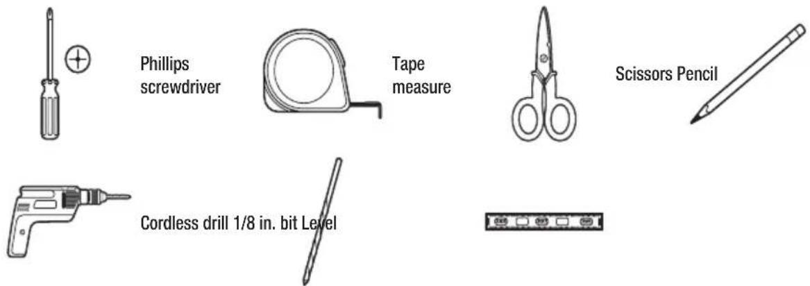
Pre-Installation (continued)
HARDWARE INCLUDED

NOTE: Check that all parts are included in parts package.

| QuantityDescriptionPart | ||
| 1A1 Adhesive seal (gray) | ||
| A2 | Adhesive seal (black) | 1 |
| 1Foam sealBB | ||
| 2Lock frame (for wooden windows)CC | ||
| 2Lock frame (for vinyl-clad windows)DD | ||
| 43/8 inch screwsEE | ||
| 73/4 inch screwsFF | ||
| 2Side curtainsGG | ||
| 1Top railHH | ||
| 1Sash lockII | ||
| 1Air conditionerKK | ||
| 1Remote controlLL | ||
| MM | Sealing sponge 1 |

NOTE:
☐ For 12/14K Btu models, top rail(HH) and 3/8inch screws (EE) had been attached by manufacturer.
☐ The MM Sealing sponge is provided only for 5K\6K BTU models.
Pre-Installation (continued)
UNPACK THE AIR CONDITIONER

WARNING: Excessive Weight Hazard
Use two or more people to move and install air conditioner.
Failure to do so can result in back or other injury.
Remove packaging materials
☐ Remove and dispose of/recycle packaging materials. Remove tape and glue residue from surfaces before turning on the air conditioner. Rub a small amount of liquid dish soap over the adhesive with your fingers. Wipe with warm water and dry.
☐ Do not use sharp instruments, rubbing alcohol, flammable fluids, or abrasive cleaners to remove tape or glue. These products can damage the surface of your air conditioner.
□ Handle the air conditioner gently.
□ Remove top rail (HH) from the packaging material (A).

LOCATION REQUIREMENTS
Before you Begin
Read these instructions completely and carefully.

IMPORTANT:
□ Save these instructions for local inspector's use.
□ Observe all governing codes and ordinances.

NOTE: Installer, be sure to leave these instructions with the Consumer.

NOTE: Consumer, keep these instructions for future reference.
☐ Skill level: Installation of this appliance requires basic mechanical skills.
☐ Completion time: Approximately 1 hour.
☐ We recommend that two people install this product.
Pre-Installation (continued)
☐ Proper installation is the responsibility of the installer.
☐ Product failure due to improper installation is not covered under the warranty.
☐ You MUST use all supplied parts and use proper installation procedures as described in these instructions when installing this air conditioner.

IMPORTANT: Observe all governing codes and ordinances.
Check the location where air conditioner will be installed. Proper installation is your responsibility. Make sure you have everything necessary for correct installation.
The location should provide:
☐ Do not use an extension cord. The appliance shall be installed in accordance with national wiring regulations.
☐ Free movement of air in room to be cooled.
☐ A large enough opening for the air conditioner.

NOTE: Cabinet louvers (A) must not be obstructed. Air must be able to pass freely through the cabinet louvers.

Pre-Installation (continued)
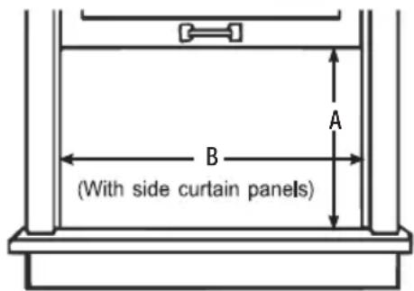
WINDOW OPENING MEASUREMENTS
These instructions are for a standard double-hung window. You will need to modify them for other types of windows.
☐ The air conditioner can be installed without the side curtain panels if needed to fit in a narrow window. See the window opening dimensions.
☐ All supporting parts must be secured to firm wood, masonry or metal.
☐ The electrical outlet must be within reach of the power cord.
☐ Follow the dimensions in the table and illustration for your model.
| Models A B | ||
| 5K BTU6K BTU | 12 2/5 inch (315 mm) min | 22 inch (559 mm) - 37 4/5 inch (960 mm) |
| 8K BTU10K BTU | 13 3/5 inch (345 mm) min | 24 1/2 inch (622 mm) - 39 inch (991 mm) |
| 12K BTU14K BTU | 15 1/5 inch (386 mm) min | 24 9/10 inch (632 mm) - 39 inch (991 mm) |
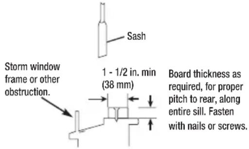
IF AC IS BLOCKED BY STORM WINDOW
Add wood as shown, or remove storm window before air conditioner is installed.
If storm window frame must remain, be sure the drain holes or slots are not caulked or painted shut. Accumulated rain water or condensation must be allowed to drain out.
1 Attaching the Top Rail

NOTE: For certain models, top rail had been attached by manufacturer.
□ Locate the bag of screws provided.
☐ Place the top rail (HH) on top of the air conditioner cabinet, lining up the 4 holes in the top rail with the 4 holes on top of the air conditioner cabinet.
☐ Using four 3/8 inch (10 mm) screws (EE), attach the top rail (HH) to the air conditioner cabinet.

2 Installing the Side Curtains

NOTE: Attach curtains to the air conditioner before placing the air conditioner in window.
☐ Slide the side curtain (GG) directly into the cabinet (B).
☐ Slide the side curtain (GG) down.
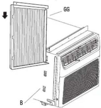

NOTE: Attach side curtains to the air conditioner before placing the air conditioner in window.
☐ Insert top and then bottom of left-hand curtain housing(A) in top rail (HH) and bottom rails (B) on air conditioner.
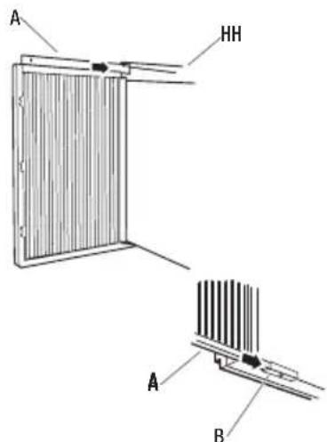
☐ Slide the curtain housing into the rails as far as it will go.
☐ Repeat above steps for the right-hand curtain.
3 Attaching the Adhesive Seal
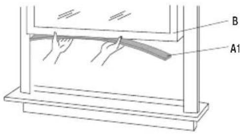
☐ Cut the adhesive seal (gray) (A1) to the width of the lower window sash (B).
☐ Remove the backing from the seal and attach the seal to the bottom of the lower window sash.
4 Placing Air Conditioner in Window

WARNING: Excessive Weight Hazard
□ Use two or more people to move and install air conditioner
□ Failure to do so can result in back or other injury.

NOTES:
☐ Handle air conditioner gently.
☐ Be sure your air conditioner does not fall out of the opening during installation or removal.
☐ Do not block the louvers in the front panel.
☐ Do not block the louvers on the outside of the air conditioner.
☐ Your model may differ from the one shown.
☐ Center air conditioner in window. Lower the window sash behind the top rail (HH) to hold cabinet in place.
- Keeping a firm grip on the air conditioner, carefully place the unit into the window opening so the bottom of the air conditioner frame is against the window sill and make sure the unit is staying center of the window.
□ Carefully close the window behind the top rail of the unit.

☐ Place the frame lock (CC) or (DD) between the curtain housing (A) and the window sill (B) with 3/4 inch (19 mm)screw (FF) as shown.

☐To secure lower sash in place, attach sash lock (II) with 3/4 inch (19 mm) screw (FF) as shown.

natural_image
Line drawing of a hand holding a tool near a metal bracket (no text or symbols)5 Attaching Side Curtains to Window
☐ Pull the left-hand side curtain out until it fits into the window channel.
☐ Use a 1/8 inch (3 mm) drill bit to drill a starter hole through the hole in the curtain housing (B).
☐ Insert one of the 3/4 inch (19 mm) screws (C) through theft-hand curtain housing (B) and into the window sash (A).
□ Repeat for the right-hand curtain.

6 Completing Installation
☐ Insert foam seal (BB) behind the top of the lower window sash (A) and against the glass of the upper window.
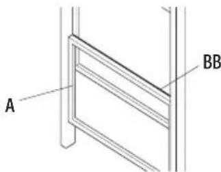
☐ Use a 1/8 inch (3 mm) drill bit to drill a starter hole through the hole in the top rail.
☐Attach top rail to window sash with one 3/4 inch (19 mm)screw to secure window in place.
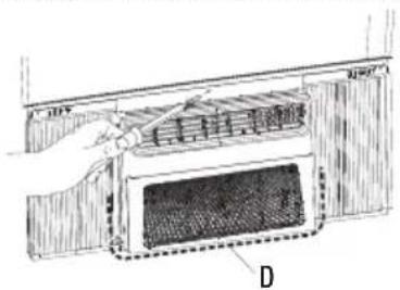
☐Check the gap (D) around the unit and seal it with the adhesive seal (black) (A2) attached.
DANGER: ELECTRICAL SHOCK HAZARD

□ Plug into a grounded 3-prong outlet.
☐ Do not remove ground prong.
☐ Do not use an adapter.
☐ Do not use an extension cord.
☐ Failure to follow these instructions can result in death, fire, or electrical shock.

□ Plug into a grounded 3-prong outlet.
☐ Press RESET on the power supply cord. See “Electrical Requirements”.
AIR CONDITIONER USE
IMPORTANT:

☐ If you turn off the air conditioner, wait at least 3 minutes before turning it back on. This prevents the air conditioner from blowing a fuse or tripping a circuit breaker.
☐ Air conditioner in the Cool mode or Dry mode operation the better limits: Outdoor 64.4-109.4°F (18-43 °C), ≤ 80% RH; indoor 62.6-89.6°F (17-32°C), ≤ 80% RH.
☐ Air conditioner in the Heat mode operation the better limits: Outdoor 19.4-75.2°F (-7-24 °C), ≤ 80% RH; indoor 32-80.6°F (0-27°C), ≤ 80% RH.
☐ In the event of a power failure, your air conditioner will operate at the previous settings when the power is restored.
☐ Operating your air conditioner properly helps you to obtain the best possible results.
☐ This section explains proper air conditioner operation.
1 Using the Control Panel
![WiFi Timer Sleep Filter CONNECT [3S] FAN Low Med High 8:10 Fan Dry Cool Eco Heat MODE ON/OFF](/content/2026/05/942899/images/1eaabe855214c6da68c4a515bd3e8af27b41c6e1c817fc58610446c522b4bd4a.jpg)

ON/OFF
ON/ OFF SETTINGS
☐ Press the power button to turn on the air conditioner.

NOTE: When the air conditioner is turned on for the first time after it is plugged in, the display will show the current set temperature and will run in the ECO control.
After cleaning and replacing the filter, press the POWER button for resetting and the FILTER light will go off.
☐ Select mode. See "Mode Settings" on page 15.
☐ Set temperature. See "Temperature Settings" on page 15.
☐ Select fan speed. See "Fan Speeds" on page 15.
Operation (continued)

MODE SETTINGS
□ Press MODE repeatedly until you see the indicator light glow for the desired setting.
□ Choose Fan, Dry, Cool, Eco.
☐ FAN - To select Fan Only mode.
☐ Dry - Dries the room. The air conditioner automatically selects the temperature. Fan runs at Low speed only.
□ Cool - Cools the room.
□ Eco - Cools the room and saves energy.
□ Heat - Heats the room.

NOTE:
□Dry mode should not be used to cool the room.
☐ Heat is available only for heating models.
☐ In ECO mode, the fan will continue to run after the compressor shuts off for 2 minutes (4 minutes for the first time), then the fan will shuts off for 10 minutes. The fan then cycles for intervals of 2 minutes on and 10 minutes off until the room temperature is above the set temperature, at which time the compressor turns back on and Cooling resumes. Select ECO mode to initiate this function.

TEMPERATURE SETTINGS
☐ Press the plus UP button to raise the temperature. Each time you press or hold the plus UP button, the temperature will go up 1 °F (1 °C) until it reaches 86°F (30°C).
☐ Press the minus DOWN √ button to lower the temperature. Each time you press or hold the DOWN √ button, the temperature will go down 1 °F (1 °C) until it reaches 61 °F (16°C).
☐ To change the temperature display from °F to °C: Press both the MODE and DOWN √ buttons at the same time for 3 seconds to switch the display from °F to °C.
FAN SPEEDS


FAN

NOTE: The Fan button will operate only when the Fan, Cool, ECO or Heat mode has been selected.
☐ Press FAN until you see the indicator light glow for the desired setting.
☐ Choose High, Med, Low.
□ High - for maximum cooling
□ Med - for normal cooling
□ Low - for quieter cooling

NOTE: In ECO mode, the Fan will run at low speed when compressor turns off.

TIMER, SLEEP, FILTER FUNCTIONS
☐ The LED light on control panel for Timer, Sleep, Filter.
☐ For function operation, see "Using the Remote Control."
![WiFi CONNECT [3S] (Optional)](/content/2026/05/942899/images/4f26f6532edb56ad8a487b47cf1160bcf93cb201d657678a7b4d392b20f7b23b.jpg)
WI-FI
□ Wi-Fi control is available for connected models with this logo on control panel.
□Press the 📤 button for 3 seconds; the LED starts to flash.
□ After the Wi-Fi connects to the router, the LED keeps on or the LED keeps off.

NOTE: Wi-Fi control is available only for Wi-Fi control models.
2 Using the Remote Control
□ Remote control may differ in appearance.


natural_image
Technical line drawing of a mechanical component with no visible text or symbolsNOTE:
☐ When the first use, please remove the insulated plastic patch.
☐ One CR2025 battery (included) powers the remote control. Replace battery after 6 months of use, or when the remote control starts to lose power.
☐ Please ensure the correct direction for polarity of the cell same as the indicator on the bracket.
☐ If Disposal of battery : old batteries must be removed and disposed of in accordance with current legislation as they are harmful to the environment.
HOW TO USE
☐ To operate the room air conditioner, aim the remote control at the signal receptor. The remote control will operate the air conditioner at a distance of up to 23' (7m) when pointed at the signal receptor.
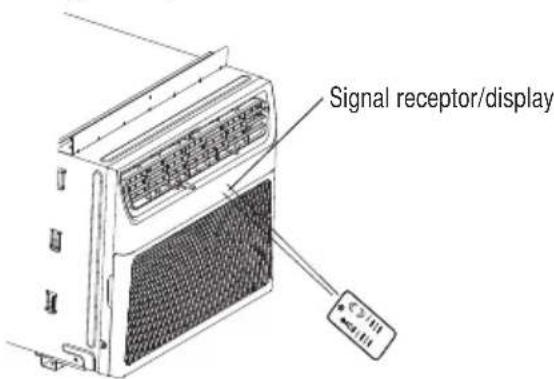
Operation (continued)

ON/OFF
Press ON/OFF button to turn on/off airconditioner.

FAN
FAN
Press FAN to select High, Med, Low.

NOTE: In Dry mode, Fan speed cannot be set.

MODE
MODE
Press MODE to select Fan, Dry, Cool, ECO, Heat.

TEMPERATURE
☐Press the plus UP(∧) button to raise the temperature. Each time you press or hold the plus UP(∧) button, the temperature will go up 1°F (1°C) until it reaches 86°F (30°C).

☐Press the minus DOWN (V) button to lower the temperature. Each time you press or hold the DOWN (V) button, the temperature will go down 1°F (1°C) until it reaches 61°F (16°C).
DIMMER
DIMMER
☐ Press the DIMMER button to turn off the control panel display.

NOTE: When in DIMMER mode, new control inputs will return display to normal.
SLEEP
SLEEP
The SLEEP mode can be set in Cool, Dry or ECO mode. When in sleep mode, the unit will utilize lower, quieter fan speeds and automatic temperature adjustments offering 8 hours of optimal sleeping conditions before shutting off.
☐ Press MODE to select Cool, Dry or ECO.

NOTE: Sleep control cannot be selected in Fan mode.
☐ Press the up or down arrow button to set the temperature.
☐Press and hold the DIMMER button on the remote for 5 seconds to switch the DIMMER mode to SLEEP mode.
□ After 10 seconds, the light on the control panel display will dim.
☐ To turn off Sleep control, press MODE, FAN, SLEEP or wait 8 hours for Sleep control to turn off automatically.

NOTE: When you press sleep button:
☐ The appliance will stop operation automatically after operating for 8 hours.
☐ Fan speed is automatically set at low speed.
☐ In the Cooling mode, Dry mode, and ECO mode, the set temperature will increase by 4^ F ( 2^ C) at most, during 2 hours, and continues running at that temperature until auto shut off.
TIMER
TIMER
Setting the Air Conditioner to Turn ON:
□ Plug in the air conditioner and use the remote to power it on.
□ Use the remote to set the desired mode, temperature, fan speed, etc.
□ Use the remote to power off the air conditioner.
☐ Press TIMER on the remote and use the UP, DOWN buttons to set the desired delay time until the air conditioner turns ON. The delay time can be set from 0 to 24 hours in one-hour increments.
☐ Press TIMER again to enter the delay time. The TIMER led on the air conditioner illuminates, and the delay time appears on the remote.
Setting the Air Conditioner to Turn OFF:
□ Plug in the air conditioner and use the remote to power it on.
□ Use the remote to set the desired mode, temperature, fan speed, etc.
☐ Press TIMER on the remote and use the UP, DOWN buttons to set the desired delay time until the air conditioner turns ON. The delay time can be set from 0 to 24 hours in one-hour increments.
☐ Press TIMER again to enter the delay time. The TIMER led on the air conditioner illuminates, and the delay time appears on the remote.
To cancel TIMER:
☐ Press the TIMER button again; when a "Beep" is heard and the indicator disappears, the TIMER mode has been canceled.

NOTE: The TIMER function can only be set using the remote.
FILTER
FILTER
☐ When the Filter indicator light is lit, remove, clean and replace the air filter. See “Cleaning the Air Filter”.
☐ Press Power button on the machine or FILTER button on remote to reset the filter after cleaning and replacing the air filter.

NOTE: When the light is on, it will remain on for 180 hours or until you press Clean Filter button.
3 Changing Air Direction
☐ Use the Vertical Level Vane (A) to direct the air right or left. Use the whole cartridge (B) to direct air up, down or straight ahead.

4 Exhaust Air Vent
☐ Pull out the exhaust air vent control to Open the exhaust air vent and draw stale or smoky air from the room.
☐ Push in the exhaust air vent control to close the exhaust air vent for maximum continuous cooling.

NOTE: The exhaust air vent control is available only for 12K\14K models.

natural_image
Technical line drawing of a mechanical component with internal channels and labeled section A (no text or symbols beyond label)
NOTE: The exhaust air vent control will function only when the fan is running.
5 Normal Sounds
When your air conditioner is operating normally, you may hear sounds such as:
☐ Droplets of water hitting the condenser, causing a pinging or clicking sound. The water droplets help cool the condenser.
□ Air movement from the fan.
□ Clicks from the thermostat cycle.
□ Vibrations or noise due to poor wall or window construction.
☐ A high-pitched hum or pulsating noise caused by the modern high-efficiency compressor cycling on and off.
6 Using the ConnectLife APP
The ConnectLife APP by Hisense provides the below features for more convenience using:
☐ Remote control& status: Turn ON/OFF, change the mode, set & monitor the temperature, and quick action buttons.
☐ Scheduler: define when your AC can automatically turn ON/OFF to defined temperatures and modes.
☐ Remote diagnostics: easily check the health of your device.
☐ Linkage with Amazon Alexa and Google Home: to easily control your AC with voice command.
DEVICES REQUIRED TO USE THE SMART AC:
□ Smart air conditioner.
☐ Wireless Router (a 2.4 GHz network is required to connect).
☐ Smart Phone with compatible iOS or Android system.
DOWNLOAD AND INSTALL THE CONNECTLIFE APP

GET IT ON Google Play

Download on the App Store
□ Scan to download the ConnectLife APP.
☐ You can also go to Google Play or App Store and search for the ConnectLife APP.
□ Follow the in-APP instructions to pair your appliance.
Care and Cleaning
Your new air conditioner is designed to give you many years of dependable service. This section tells you how to clean and care for your air conditioner properly. Call your local authorized dealer for an annual checkup. Remember the cost of this service call is your responsibility.
CLEANING THE AIR FILTER
The air filter is removable for easy cleaning. A clean filter helps remove dust, lint, and other particles from the air and is important for best cooling and operating efficiency. Check the filter every 2 weeks to see whether it needs cleaning.

NOTE: Do not operate the air conditioner without the filter in place.
□ Turn off the air conditioner.
Open the front panel. Grasp the filter by the handle and pull it out.

natural_image
Technical line drawing of an air vent system with labeled component A (no text or symbols beyond label)☐ Use a vacuum cleaner to clean the air filter. If the air filter is very dirty, wash it in warm water with a mild detergent. Do not wash the air filter in the dishwasher or use any chemical cleaners. Air dry the filter completely before replacing to ensure maximum efficiency.
☐ Replace the air filter back into the air conditioner.
CLEANING THE FRONT PANEL
□ Turn off the air conditioner.
□ Clean the front panel with a soft, damp cloth.
□ Air dry the front panel completely.
REPAIRING PAINT DAMAGE
Check once or twice a year for paint damage. This is very important, especially in areas near oceans or where rust is a problem. If needed, touch up with a good grade enamel paint.
ANNUAL MAINTENANCE
Your air conditioner needs annual maintenance to help ensure steady, top performance throughout the year. Call your local authorized dealer to schedule an annual checkup. The expense of an annual inspection is your responsibility.
REMOVING AC FROM WINDOW
☐ Turn AC off, and disconnect power cord.
☐ Remove sash seal from between windows and unscrew safety lock.
☐ Remove screws installed through frame and frame lock. Remove the EVA foam (E-star models only).
□ Close the curtain housing.
□ Keeping a firm grip on air conditioner, raise sash and carefully remove.
☐ Be careful not to spill any standing water while lifting unit from window. Store parts with the AC.
Troubleshooting
| Problem Solution | |
| Air conditioner will not operate | DANGER: ELECTRICAL SHOCK HAZARDPlug into a grounded 3-prong outlet.Do not remove ground prong.Do not use an adapter.Do not use an extension cord.Failure to follow these instructions can result in death, fire, or electrical shock. |
| The power supply cord is unplugged. Plug into grounded 3-prong outlet. See “Electrical Requirements”.The power supply cord has tripped (RESET button has popped out). Press and release RESET to resume operation.A household fuse has blown, or circuit breaker has tripped. Replace the fuse or reset the circuit breaker. If the problem continues, call an electrician. See “Electrical Requirements”.The Power button has not been pressed. Press the Power button.The local power has failed. Wait for power to be restored. | |
| Air conditioner blows fuses or trips circuit breakers | Too many appliances are being used on the same circuit. Unplug or relocate appliances that share the same circuit.Time-delay fuse or circuit breaker of the wrong capacity is being used. Replace with a time-delay fuse or circuit breaker of the correct capacity. See “Electrical Requirements”.An extension cord is being used. Do not use an extension cord with this or any other appliance.You are trying to restart the air conditioner too soon after turning off the air conditioner. Wait at least 3 minutes after turning off the air conditioner before trying to restart the air conditioner. |
| Air conditioner power supply cord trips (Reset button pops out) | Disturbances in your electrical current can trip (RESET button will pop out) the power supply cord. Press and release RESET to resume operation.Electrical overloading, overheating, cord pinching or aging can trip (RESET button will pop out) the power supply cord. After correcting the problem, press and release RESET to resume operation.NOTE:A damaged power supply cord must be replaced with a new power supply cord obtained from the product manufacturer and must not be repaired. |
| Air conditioner seems to run too much | The current air conditioner replaced an older model. The use of more efficient components may cause the air conditioner to run longer than an older model, but the total energy consumption will be less. Newer air conditioners do not emit the “blast” of cold air you may be accustomed to from older air conditioners, but this is not an indication of lesser cooling capacity or efficiency. Refer to the efficiency rating (EER) and capacity rating (in Btu/h) marked on the air conditioner.The air conditioner is in a heavily occupied room, or heat producing appliances are in use in the room. Use exhaust vent fans while cooking or bathing and try not to use heat producing appliances during the hottest part of the day. A higher capacity air conditioner may be required, depending on the size of the room being cooled. |
| Air conditioner cycles on and off too much or does not cool | The air conditioner is not properly sized for your room. Check the cooling capabilities of your room air conditioner. Room air conditioners are not designed to cool multiple rooms.The filter is dirty or obstructed by debris. Clean the filter.The inside evaporator and outside condenser coils are dirty or obstructed by debris. See Annual Maintenance.There is excessive heat or moisture (open container cooking, showers, etc.) in the room. Use a fan to exhaust heat or moisture from the room. Try not to use heat producing appliances during the hottest part of the day.The louvers are blocked. Install the air conditioner in a location where the louvers are free from curtains, blinds, furniture, etc.The temperature of the room you are trying to cool is extremely hot. Allow extra time for the air conditioner to cool off a very hot room.Windows or doors to the outside are open. Close all windows and doors.The Temp control is not at a cool enough setting. Adjust the Temp control to a cooler setting by pressing the minus button to reduce the temperature. Set the Fan Speed control to the highest setting. |
| Water drips from cabinet into your house | The air conditioner is not properly leveled. The air conditioner should slope slightly downward toward the outside. Level the air conditioner to provide a downward slope toward the outside to ensure proper drainage. See the Installation Instructions. NOTE: Do not drill a hole in the bottom of the metal base and condensate pan. NOTE: Do not drill a hole in the bottom of the metal base and condensate pan. |
Circuit diagram

flowchart
graph TD
    A["2142719"] --> B["POWER UNIT"]
    B --> C["X101"]
    B --> D["X800"]
    B --> E["X400"]
    B --> F["X410"]
    B --> G["X940"]
    B --> H["X900"]
    B --> I["DISPLAY UNIT"]
    J["HEATER"] --> K["BU N PTC_N K816"]
    K --> L["BLK"]
    L --> M["COMP K800"]
    N["THERMISTOR (ROOM TEMP.)"] --> O["TH1 θ"]
    O --> P["X400"]
    P --> Q["TH2 θ"]
    Q --> R["X410"]
    R --> S["X940"]
    T["THERMISTOR (INNER PIPE TEMP.)"] --> U["X400"]
    U --> V["X410"]
    V --> W["X940"]
    X["FAN CAPACITOR"] --> Y["M ~"]
    Y --> Z["FAN MOTOR (INTERNAL PROTECTOR)"]
    AA["MOTOR PROTECTOR (INTERNAL OR OUTER)"] --> AB["RD S C"]
    AC["COMPRESSOR MOTOR"] --> AD["YE/GN"]
    AE["optional"] --> AF["optional"]
    AG["optional"] --> AH["optional"]
    AI["optional"] --> AJ["optional"]
Tabla de Contenidos

natural_image
Line drawing of a hand holding a tool near a bracket (no text or symbols)natural_image
Technical line drawing of a structural frame with labeled points A and BB (no text or symbols beyond labels)natural_image
Diagram of a hand holding a tool interacting with a grid-patterned panel inside a container (no text or symbols visible)natural_image
Technical line drawing of a mechanical component with internal channels and labeled section A (no text or symbols beyond label)
natural_image
Technical diagram of a mechanical ventilation system with mesh grille and labeled component A (no text or symbols beyond labels)flowchart
graph TD
    A["POWER UNIT"] --> B["X101"]
    B --> C["BU"]
    C --> D["PTC_N"]
    D --> E["K816"]
    E --> F["L"]
    F --> G["K815"]
    G --> H["HEATER"]
    H --> I["RD"]
    I --> J["PTC_L"]
    J --> K["K815"]
    K --> L["X400"]
    L --> M["TH1"]
    M --> N["1"]
    N --> O["2"]
    O --> P["X940"]
    P --> Q["X900"]
    Q --> R["DISPLAY UNIT"]

    S["THERMISTOR (ROOM TEMP.)"] --> T["TH1"]
    T --> U["X400"]
    U --> V["TH2"]
    V --> W["X410"]
    W --> X["X940"]

    Y["FAN MOTOR (INTERNAL PROTECTOR)"] --> Z["M"]
    AA["FAN MOTOR"] --> AB["YE/GN"]
    AC["MOTOR PROTECTOR (INTERNAL OR OUTER)"] --> AD["RD"]
    AE["MOTOR PROTECTOR"] --> AF["S"]
    AG["COMPRESSOR MOTOR"] --> AH["YE/GN"]

    subgraph Power Unit
        B
        C
        D
        E
        F
        G
        H
        I
        J
        K
        L
        M
        N
        O
        P
        Q
        R
        S
        T
        U
        V
        W
        X
        Y
        Z
        AA
        AB
        AC
        AD
        AE
        AF
        AH
        AI
        AJ
        AK
        AL
        AM
        AN
        AO
        AP
        AQ
        AR
        AS
        AT
        AU
        AV
        AW
        AX
        AY
        AZ
        BA
        BB
        BC
        BD
        BE
        BF
        BG
        BH
        BI
        BJ
        BK
        BL
        BM
        BN
        BO
        BP
        BQ
        BR
        BS
        BT
        BU
        BV
        BW
        BX
        BY
        BZ
        CA
        CB
        CC
        CD
        CE
        CF
        GD
        GH
        BIY
        BJY
        BKY
        BLY
        BMY
        BNY
        BOY
        BXY
        BYX
    end
- Pre-Installation....7
- Installation 13
- Operation.... 16
- Care and Cleaning 23
- Troubleshooting 24
- Circuit diagram 26
- Safety Information
- IMPORTANT SAFETY INSTRUCTIONS
- DISPOSING OF THE UNIT
- Safety Information (continued)
- Precautions for using R32 refrigerant
- Storage of packed (unsold) equipment
- Information on servicing
- Repairs to sealed components
- Repairs to intrinsically safe components
- Cabling
- Detection of flammable refrigerants
- Leak detection methods
- Removal and evacuation
- Charging procedures
- Decommissioning
- Labelling
- 16.Recovery
- ELECTRICAL REQUIREMENTS
- WARNING: Electrical Shock Hazard
- RECOMMENDED GROUNDING METHOD
- WIRING REQUIREMENT
- Pre-Installation (continued)
- PLANNING INSTALLATION
- HARDWARE INCLUDED
- NOTE:
- UNPACK THE AIR CONDITIONER
- Remove packaging materials
- LOCATION REQUIREMENTS
- Before you Begin
- IMPORTANT:
- WINDOW OPENING MEASUREMENTS
- IF AC IS BLOCKED BY STORM WINDOW
- Attaching the Top Rail
- Installing the Side Curtains
- Attaching the Adhesive Seal
- Placing Air Conditioner in Window
- WARNING: Excessive Weight Hazard
- NOTES:
- Attaching Side Curtains to Window
- Completing Installation
- DANGER: ELECTRICAL SHOCK HAZARD
- AIR CONDITIONER USE
- Using the Control Panel
- ON/ OFF SETTINGS
- Operation (continued)
- MODE SETTINGS
- TEMPERATURE SETTINGS
- FAN SPEEDS
- TIMER, SLEEP, FILTER FUNCTIONS
- WI-FI
- Using the Remote Control
- HOW TO USE
- ON/OFF
- FAN
- MODE
- TEMPERATURE
- DIMMER
- SLEEP
- TIMER
- FILTER
- Changing Air Direction
- Exhaust Air Vent
- Normal Sounds
- Using the ConnectLife APP
- DEVICES REQUIRED TO USE THE SMART AC:
- DOWNLOAD AND INSTALL THE CONNECTLIFE APP
- Care and Cleaning
- CLEANING THE AIR FILTER
- CLEANING THE FRONT PANEL
- REPAIRING PAINT DAMAGE
- ANNUAL MAINTENANCE
- REMOVING AC FROM WINDOW
- Circuit diagram
- Tabla de Contenidos
Brand : HISENSE
Model : AHW0621CR1W
Category : Air conditioner