
M-700u - Receiver LUXMAN - Free user manual and instructions
Find the device manual for free M-700u LUXMAN in PDF.


| Product Type | Stereo Power Amplifier |
| Dimensions (W x H x D) | 440 mm x 190 mm x 427 mm |
| Weight | 27.5 kg |
| Power Supply | 230 V ~ 50 Hz |
| Power Consumption (Rated) | 370 W |
| Power Consumption (Standby) | 0.4 W |
| Continuous Rated Output (Stereo) | 120 W + 120 W (8 Ω); 210 W + 210 W (4 Ω) |
| Continuous Rated Output (BTL) | 420 W (8 Ω) |
| Instantaneous Maximum Output (Stereo) | 840 W + 840 W (1 Ω) |
| Instantaneous Maximum Output (BTL) | 1680 W (2 Ω) |
| Input Sensitivity | 1.1 V (120 W, 8 Ω) |
| Gain | 29.0 dB |
| Input Impedance (LINE) | 51 kΩ |
| Input Impedance (BAL LINE) | 34 kΩ |
| Total Harmonic Distortion | ≤0.009% (1 kHz, 120 W, 8 Ω) |
| Frequency Response | +0, -0.1 dB (20 Hz - 20 kHz); +0, -3.0 dB (1 Hz - 130 kHz) |
| Signal-to-Noise Ratio (IHF-A) | 115 dB |
| Damping Factor | 350 |
| Amplifier Circuit | 4-parallel push-pull with 3-stage Darlington, ODNF 4.0 feedback |
| Inputs | Unbalanced (RCA) and Balanced (XLR) with phase selection |
| Speaker Impedance (Stereo) | 4 - 16 Ω |
| Speaker Impedance (BTL) | 8 - 16 Ω |
| Power Meter | Large analog meters with shower light, selectable display |
| Protection Circuit | Overcurrent, temperature, DC drift protection |
| Accessories Included | Power cable, dedicated remote cable, owner’s manual, safety cautions |
Frequently Asked Questions - M-700u LUXMAN
User questions about M-700u LUXMAN
0 question about this device. Answer the ones you know or ask your own.
Ask a new question about this device
Download the instructions for your Receiver in PDF format for free! Find your manual M-700u - LUXMAN and take your electronic device back in hand. On this page are published all the documents necessary for the use of your device. M-700u by LUXMAN.
USER MANUAL M-700u LUXMAN
Features of This Unit 2
Names and Functions 4
Connections 8
Block Diagram 12
Specifications 13
Before Asking for Repair Services 14
Precautions
Installation place
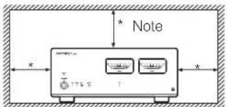
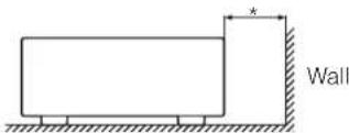
Install this unit in a location where good ventilation and heat radiation is assured.
Especially, placing this unit where direct sunlight is present, where the temperature rises excessively high such as close to a heater, or where it is humid or dusty may cause a malfunction even if heat is efficiently released.
Ventilation holes
Do not block the ventilation holes of the top and bottom panels. If the amplifier is installed on a rack or the like, secure ample space for cooling and leave the door open. Do not pile up other things on the amplifier and never put articles on it. Failure to observe this may cause a malfunction.
Note:
For heat dispersal, do not install this equipment in a confined space such as a book case or similar unit.
Precautions in connecting with other components
When connecting this product with a control amplifier and such, be sure to turn off the power of this product and all other connected devices. Failure to observe this may generate a strong noise resulting in speaker damage or a malfunction. The pin-plug to be inserted in each input terminal of this unit shall be pushed in firmly. If the grounding terminal is inadequately connected, noises including hum may be generated, resulting in an adverse S/N ratio.
Cautions in connecting speakers
When making speaker system connections, exercise extra care not to short-circuit between and of the speaker terminals and speaker input terminals of this unit.
If a large signal is applied to the amplifier with its circuit left short-circuited, a large current may be passed through the output circuit and cause a malfunction.
The sound is not generated shortly after the power supply is turned on.
This amplifier is equipped with a time muting circuit in order to separate the output circuit. Therefore, no sound is generated shortly after the power supply is turned on.
If the volume control is moved to a high sound level before the time muting circuit is canceled, a large sound is suddenly generated. Please be advised that the volume control of the input device such as a control amplifier shall be set to a low level at first and adjusted according to your taste after sound comes out of the speakers.
Protection circuit
This product is equipped with a protection circuit that is activated upon detection of overcurrent, abnormally high temperature, and DC drift to protect the amplifier and speakers. When the protection circuit is activated, the output to the speaker terminal is shut off and the standby indicator lights up to show that this product is in the standby state. Please consult your dealer when the protection circuit is sometimes activated even after turning off the switch, disconnecting the power plug from the wall outlet, and connecting it again after a while.
Repair and adjustment
When repair and adjustments are needed, please ask the dealer where you bought the unit.
Cleaning
For cleaning, use a piece of soft cloth to wipe the unit such as cleaning cloth. When the dirt is hard to remove, use a small amount of neutral detergent to wipe, and then wipe the unit with dry cloth. Do not use a solvent like benzine or thinner because such a substance can often damage the exterior.
SAFETY CAUTIONS
CAUTION
Exercise extra care when this unit is unpacked, assembled, transported, and installed because this unit is heavy.
Features of This Unit
4 parallel push-pull output stages
4-parallel push-pull amplification circuit structured with 3-stage Darlington.
Rated output of 120 W+120 W (8Ω), 210 W+210 W (4Ω).
ODNF
- Only Distortion Negative Feedback -
The amplification feedback circuit that has acquired the high-speed primary slew rate and ultra-wide bandwidth by feeding back only distortion components generated during amplification for the main amplifier to maintain the pure sound quality that is almost non-feedback.
With ODNF's latest version 4.0, in the amplification circuit, the first stage is 4-parallelized and the second stage is connected with Darlington. Due to these improvements, the low impedance and high S/N ratio of the transmission circuit have become possible.
In addition, the input stage of the error detection circuit is 3-parallelized to improve distortion and noise.
BTL connection mode
The BTL connection mode with use of 2 units of this product has achieved a high-quality and high-power monaural amplifier structure.
2-channel input selector
Switching between unbalanced input of RCA terminal supporting large plugs and balanced input of XLR terminal manufactured by Neutrik that supports high-grade balanced signal transmission is possible.
Balanced input phase selection
Balanced input phase selection switch is equipped, which is useful for the case of connecting foreign-made input devices.
Selector relay
Selector relay with high sound quality used in Luxman amplifiers enhances the separation and crosstalk performances.
High-inertia power supply
L and R separated high-inertia power supply circuit combining a large-capacity El-core-type power transformer with customizable 10,000 F × 8 block capacitors are used.
4-parallel speaker relay
Impedance of speaker output lines is reduced thanks to 4-parallel structure of speaker relays with low resistance value for each channel.
Schottky barrier diode
In the power supply rectifier circuit, schottky barrier diode manufactured by Nihon Inter Electronics Corporation that has less switching noises and higher conversion efficiency to the DC voltage is applied.
LUXMAN's original OFC wires
Our original OFC wires are used in the internal wiring to achieve smooth signal transmission thanks to the spiral wrap shielding on each core and the non-plating processing on the core wire.
High-grade analog meter
Large-sized analog meter with shower light is equipped. Light OFF/meter OFF is selectable.
Loopless chassis
The independent construction of a loopless chassis structure eliminates the rise of increased ground impedance caused by chassis current.
Large type of speaker terminals
Speaker terminals of right and left identical layout, compatible with Y lugs, and allow extra-thick speaker cables to be connected easily.
AC inlet
This inlet enables the connection with an external power cable.
Cast-iron insulator
The gradation cast-iron insulator that clears unnecessary external vibration and strongly supports the weight of this unit is equipped.
Names and Functions
Front panel
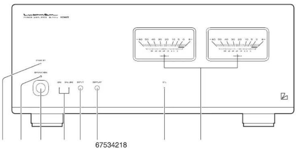
1. Standby indicator (STAND BY)
Indicates that this unit is in the standby state.
This indicator lights up when the operation switch is turned off after the main power switch on the rear panel is turned on.
When the operation switch is turned on and when the main power switch is turned off, this indicator turns off.
2. Operation indicator (OPERATION)
Blinks (for approx. 15 sec.) when the unit is in a muting mode, when the operation switch is turned on. Then it lights up when the unit is in the operation state afterward.
3. Operation switch (OPERATION)
Turns this unit from the standby state to operation state.
When the main power switch on the rear panel is turned on to set this unit to the standby state, turn this switch on.
Then this unit is set to the operation state.
When wiring or connection is performed, be sure to turn off this switch.
4. Input indicator (LINE/BAL LINE)
Indicates the input selected with the input switch.
5. Input switch (INPUT)
Selects the unbalanced input terminal (LINE) or balanced input terminal (BAL LINE), both of which are located on the rear panel.
Every time this switch is pressed, the selection changes as follows: LINE→BAL LINE→LINE→BAL LINE→LINE...
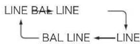
Factory default: LINE
When this switch is toggled, the input/output muting circuit is activated and no sound is generated during the time.
6. Display switch (DISPLAY)
Selects the power meter light and display.
This switch operates differently depending on the setting of the BTL selection switch on the rear panel.
When STEREO is selected:
- Every time this switch is pressed, the setting changes as follows: light ON/power meter ON→light OFF/power meter ON→light OFF/power meter OFF→light ON/power meter ON...
When BTL (MONO) is selected:
- Only the power meter at the left side operates.
- Every time this switch is pressed, the setting changes as follows: right and left lights ON/power meter (left) ON→left light ON/power meter (left) ON→light OFF/power meter (left) ON→light OFF/power meter OFF→right and left lights ON/power meter (left) ON...
Factory default: as follows
At STEREO, power meter light ON power meter display ON
At BTL (MONO), power meter right and left lights ON power meter display ON (left)
The setting of the display switch is memorized in both STE-REO and BTL (MONO), respectively.
7. BTL indicator (BTL)
Lights when the BTL selection switch on the rear panel is set to BTL (MONO) to show that this unit turns to a monaural amplifier with BTL connection.
When the BTL selection switch is set to STEREO, this indicator turns off to show that this unit turns to a stereo amplifier with normal connection.
Factory default: No lighting (STEREO)
8.Powermeters
Indicates the level of output to the speakers, with lighting equipped.
The light/power meter operate differently depending on the setting of the display switch and the setting of the BTL selection switch on the rear panel.
- This meter indicates the output level in decibels from -60dB through +6 dB during the power meter in operation.
- When STEREO is selected, the meter at left reads the level of the L channel, and the meter at right reads the level of the R channel.
- When BTL (MONO) is selected, the level is indicated only with the left meter.
Names and Functions
Rear panel
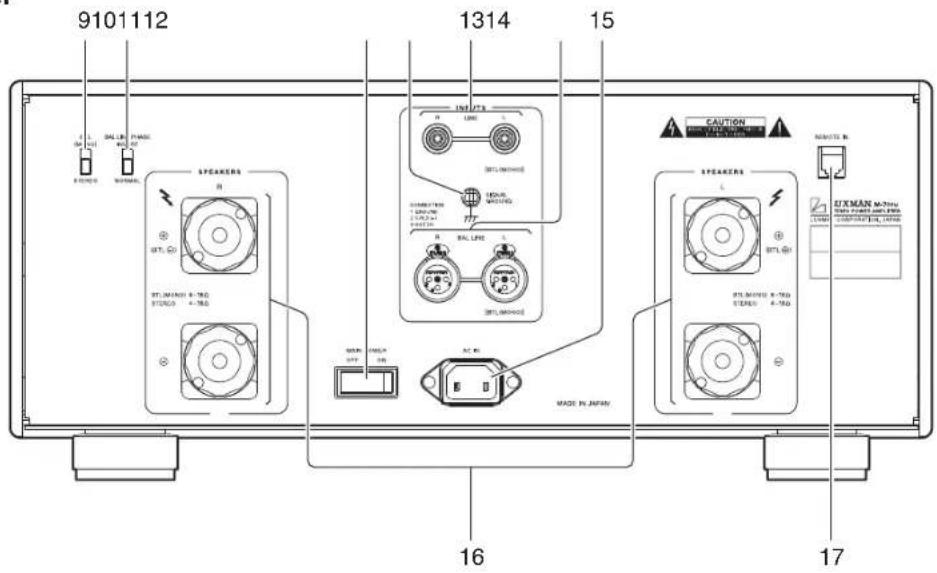
9. STEREO/BTL selection switch (STEREO/BTL (MONO))
When STEREO is selected, this unit operates as a stereo power amplifier.
When BTL (MONO) is selected, this unit operates as a monaural power amplifier with BTL connection.
Factory default: STEREO
10. Phase inverter switch (BAL LINE PHASE)
Changes the phase when the balance input terminal is used. The phase shall be set with the phase of the input device.
NORMAL Position ① GROUND
② COLD (-)
③ HOT (+)
INVERT Position ① GROUND
② HOT (+)
③ COLD (-)
11. Main power switch (MAIN POWER)
Turns this unit to the standby state.
When this switch is turned on, the standby indicator on the front panel lights (yellow) to show that this unit turns to the standby state.
When this switch is turned off, the standby indicator on the front panel turns off to show that the main power is turned off.
12. Signal ground (ground terminal) (SIGNAL GROUND)
Is a ground terminal for devices to be connected to this unit. This terminal is used to reduce noise when other devices are connected. This is not the earth terminal for safety.
13. Unbalanced input terminal (INPUTS LINE)
Is a coaxial input terminal to receive unbalanced audio signals of a line level.
Connect this terminal to an unbalanced output of an input device such as a control amplifier with a pin-plug cable.
Audio input signals coming to LINE are selected by the input switch on the front panel and delivered.
14. Balanced input terminal (INPUTS BAL LINE)
Is a XLR connector input terminal to receive balanced audio signals of a line level.
Connect this terminal to a balanced output of an input device such as a control amplifier with a balanced cable.
Audio input signals coming to BAL LINE are selected by the input switch on the front panel and delivered.
To enjoy sound reproduction properly, set the phase inverter switch in accordance with the phase of the balanced output of the input device.
When BTL (MONO) is selected, only signals from the L side are valid, and therefore, securely connect the left channel output terminal (L side) of the input device to the L side input terminal of M-700u for the left channel and the right channel output terminal (R side) of the input device to the L side input terminal of another M-700u for the right channel.
Signals from the R side input terminal are not provided.
15. AC inlet (AC IN)
Connects the accessory power cable.
The power shall be supplied from a household wall socket.
16. Speaker terminals (SPEAKERS)
Connect the left speaker to the L side speaker terminal of this unit and the right speaker to the R side speaker terminal in consideration of the polarity.
Securely connect the ⊕ terminal of the speaker system to the speaker terminal ⊕ (red) of this unit, and the ⊖ terminal of the speaker system to the speaker terminal ⊗ (black) of this unit.
Speaker systems with impedance of 4-16 Ω can be connected to this unit.
When BTL (MONO) is selected, this unit acts as a monaural power amplifier. Therefore, either right or left speaker system can be connected exclusively.
If stereo playback is desired, another M-700u is required.
When BTL (MONO) is selected, securely connect the ⊕ terminal of the speaker system to the ⊕ terminal (red) (BTL⊕) of the L side speaker terminal of this unit, and the ⊖ terminal of the speaker system to the ⊕ terminal (red) (BTL⊖) of the R side speaker terminal of this unit.
Speaker systems with impedance of 8-16 Ω can be connected to this unit in the BTL mode.
17. Remote input terminals (REMOTE IN)
Connects a control amplifier (e.g. C-700u) equipped with dedicated remote output terminal using a dedicated remote cable.
If the main power switch is turned on and this unit is turned to the standby state, this unit can be turned to the operating state or standby state in conjunction with the operation switch of a control amplifier.
When the main power switch is turned off, this unit does not operate in conjunction with the control amplifier.
Memory reset
The following operations restore all the settings to the factory defaults.
(1) Turn the power supply to the standby state.
(2) Perform the following operations while pressing the display switch.
(3) Turn on the operation switch.
(4) The input indicator, LINE, and BAL LINE light up in 5 seconds after (3).
(5) Press the input switch once.
(6) The power supply turns to the standby state.
(7) Release the display switch.
The memory reset is done.
Factorydefault
ItemDefault
Input LINE
Display
At STEREO
Power meter light ON
Power meter display ON
At BTL (MONO)
Power meter right and left lights ON
Power meter display ON (left)
Connections
Before Connecting
Before connecting other devices, connect the jack side of the accessory power cable to the AC inlet of this unit.
Before any connection is made, turn off the main power switch of this unit and the power of all the other connected devices to prevent unexpected accidents that may be caused by noise.
How to connect power supply
Use the accessory power cable and insert the AC plug in an outlet on the wall in the room where the unit will be installed.
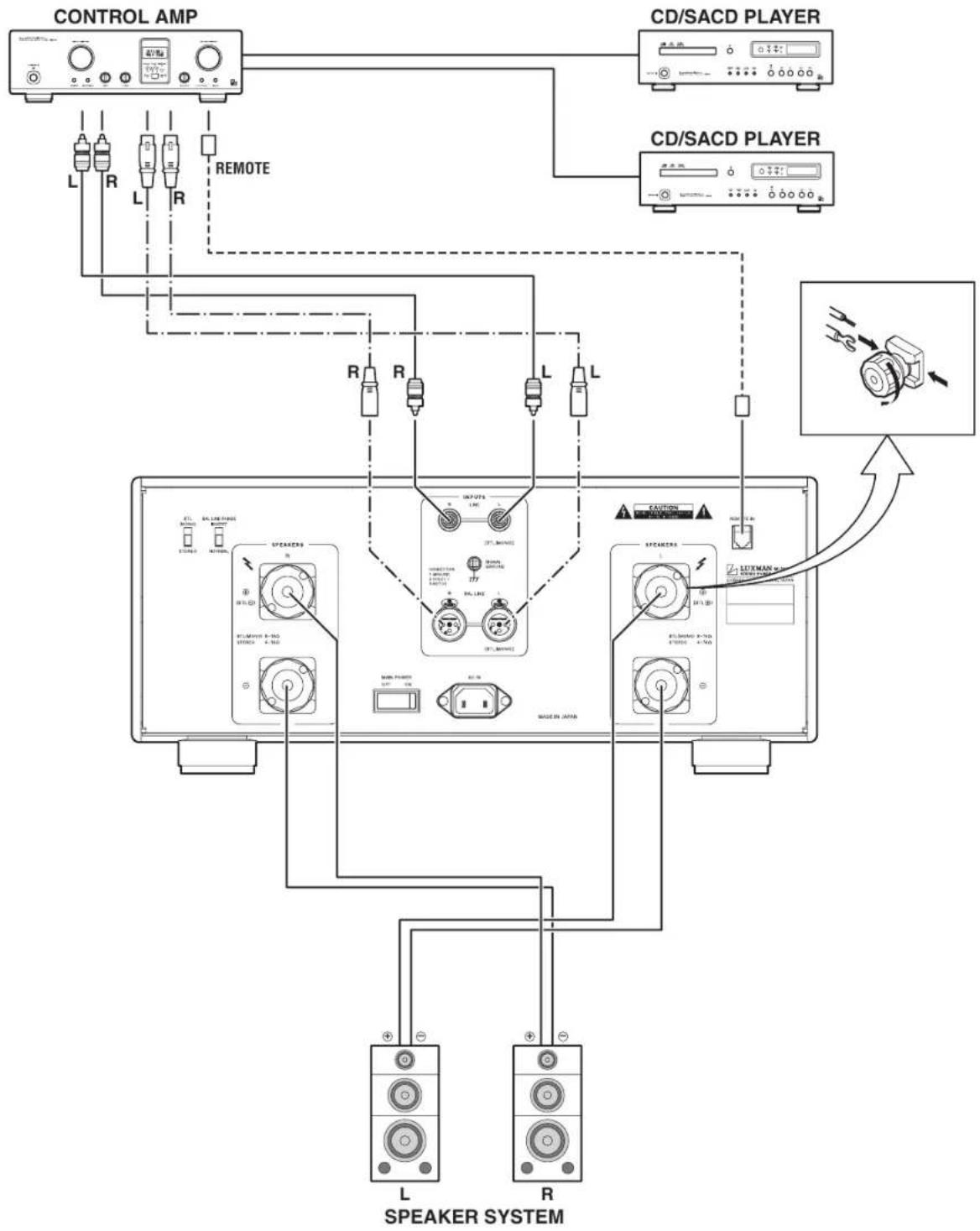
How to connect the input terminals to input devices such as a control amplifier
Connect between the output terminal of an input device such as a control amplifier and the input terminal of this unit with a pin-plug cable or a balanced cable.
Please be very careful to prevent wrong connection between right and left channels. If the right and left channels are connected reversely, the localization of sound images is deteriorated, thus failing in normal stereo playback.
If pin-plug cables are used, inadequate connection of the grounding of the cables may generate noises including hum, resulting in an adverse S/N ratio. Firmly insert the connection plug.
How to connect the remote input terminal to a control amplifier
Connect between the remote output terminal of a control amplifier such as Luxman G-700u and the remote input terminal of this unit with the dedicated remote cable supplied with this unit.
After this connection, this unit can be turned to the operating state in conjunction with the operation switch of the control amplifier.
Use the dedicated remote cable only for the connection between this unit and Luxman control amplifiers.
How to connect speakers
[stereo connection]
Connect the left-channel speaker to the SPEAKER L terminal of this unit and the right-channel speaker to the SPEAKER R terminal.
Securely connect the ⊕ terminal of the speaker system to the speaker terminal ⊕ (red) of this unit, and the ⊖ terminal of the speaker system to the speaker terminal ⊖ (black) of this unit. If the ⊕ and ⊖ terminals are reversely connected to either of the right and left speaker systems, the acoustic phases of the signals reproduced from the right and left speaker systems are also reversed. In such a case, the sound level in the low range may be reduced and the acoustic stability may worsen, thus failing in normal stereo playback.
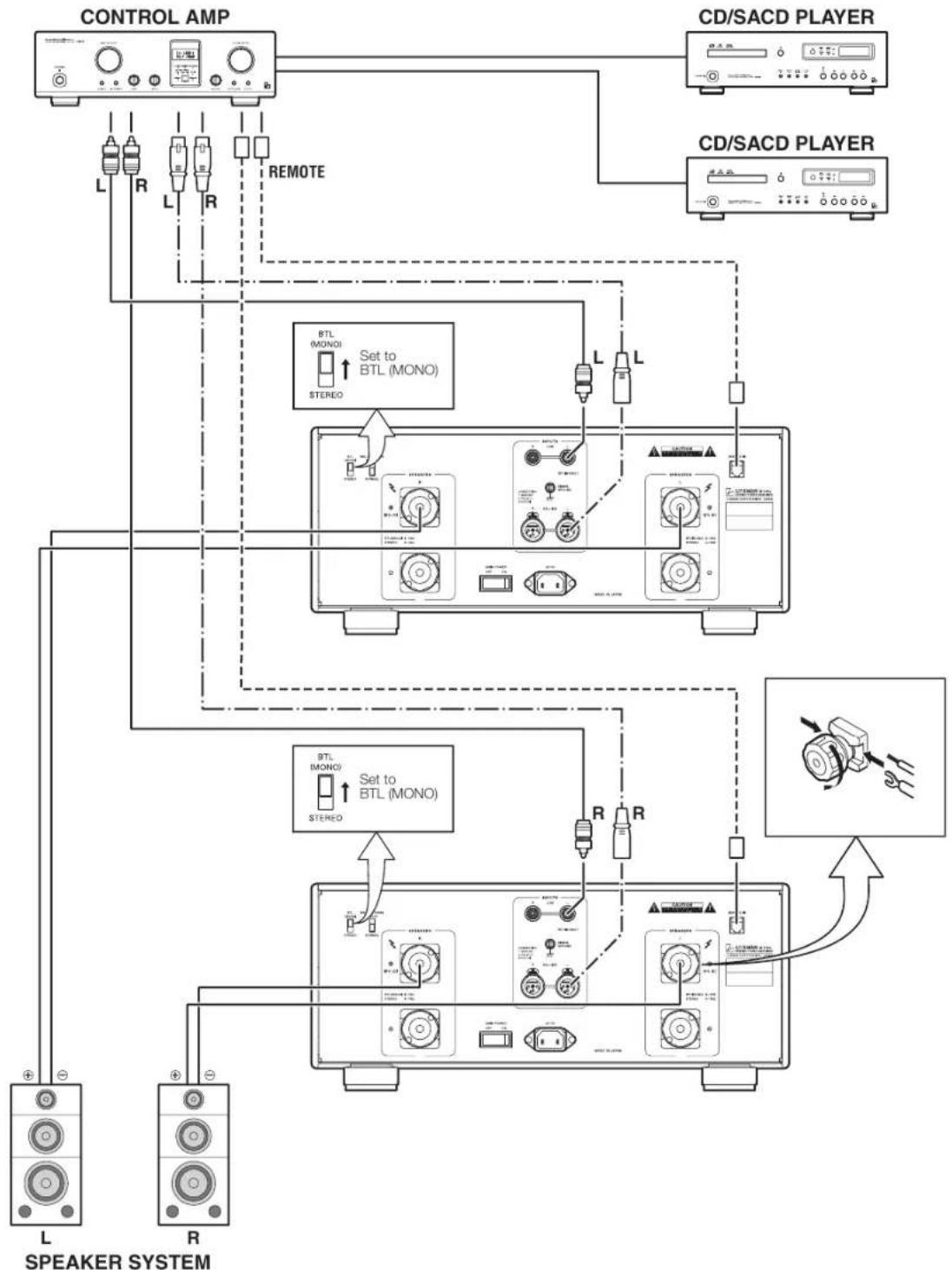
[BTL connection]
When BTL (MONO) is selected, this unit turns to a monaural power amplifier, another M-700u is required for stereo play-back.
Connect the left-channel speaker to the speaker terminal of M-700u for the left channel, and the right-channel speaker to the speaker terminal of M-700u for the right channel.
Securely connect the ⊕ terminal of the speaker system to the red SPEAKERS L terminal (BTL ⊕) of this unit, and the ⊖ terminal of the speaker system to the red SPEAKERS R terminal (BTL ⊖) of this unit.
Take extra care not to connect in reverse polarity or reverse right/left channel to perform normal stereo playback.
Some speaker selection switch boxes have the speaker terminal connected to the common ground terminal.
When BTL (MONO) is selected, the inverted output side of this unit is short-circuited to the common ground and excessive current flows into this unit.
The protection circuit will be activated in such a case. This may cause a breakdown. Therefore, do not use such a switch box.
When BTL (MONO) is selected, this unit shall be directly connected to speaker systems, or the switch box with which the speaker terminal can be independently selected shall be used.
When this unit is connected to an input device or a speaker system, turn off the main power switch of this unit or turn this unit to the standby state to protect the amplifier and speakers from excessive input.
After connection, ensure that connections are appropriately performed and turn this unit to the operating state.
Connections
Normal stereo playback
flowchart
graph TD
    A["CONTROL AMP"] -->|L R L R REMOTE| B["CD/SACD PLAYER"]
    A -->|R R L L| C["Speaker System"]
    B --> D["CD/SACD PLAYER"]
    C --> E["Speaker System"]
    D --> F["L Speaker System"]
    E --> G["R Speaker System"]
    style A fill:#f9f,stroke:#333
    style B fill:#ccf,stroke:#333
    style C fill:#cfc,stroke:#333
    style D fill:#fcc,stroke:#333
    style E fill:#cff,stroke:#333
    style F fill:#ffc,stroke:#333
    style G fill:#fcc,stroke:#333
BTL stereo playback
flowchart
graph TD
    A["CONTROL AMP"] -->|L R L R| B["CD/SACD PLAYER"]
    A -->|REMOTE| C["CD/SACD PLAYER"]
    B --> D["Speaker System"]
    C --> D
    D --> E["L"]
    D --> F["R"]
    E --> G["BTL (MONO)"]
    E --> H["STEREO"]
    F --> I["BTL (MONO)"]
    F --> J["STEREO"]
    G --> K["Set to BTL (MONO)"]
    H --> L["Set to BTL (MONO)"]
    I --> M["SET to BTL (MONO)"]
    J --> N["SET to BTL (MONO)"]
    K --> O["Output"]
    L --> P["Output"]
    M --> Q["Output"]
    N --> R["Output"]
Block Diagram
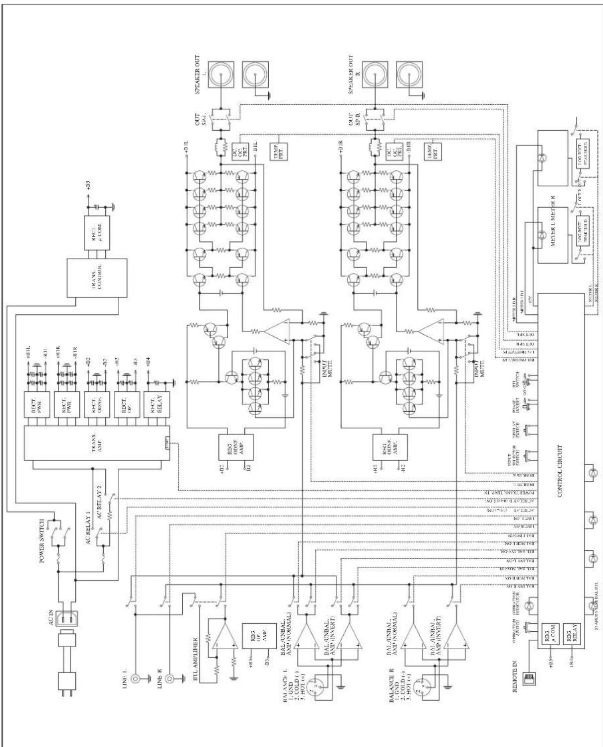
flowchart
graph TD
    A["ACIN"] --> B["AC RELAY 1"]
    B --> C["AC RELAY 2"]
    C --> D["AC RELAY 1"]
    D --> E["AC RELAY 2"]
    E --> F["AC RELAY 1"]
    F --> G["AC RELAY 2"]
    G --> H["AC RELAY 1"]
    H --> I["AC RELAY 2"]
    I --> J["AC RELAY 1"]
    J --> K["AC RELAY 2"]
    K --> L["AC RELAY 1"]
    L --> M["AC RELAY 2"]
    M --> N["AC RELAY 1"]
    N --> O["AC RELAY 2"]
    O --> P["AC RELAY 1"]
    P --> Q["AC RELAY 2"]
    Q --> R["AC RELAY 1"]
    R --> S["AC RELAY 2"]
    S --> T["AC RELAY 1"]
    T --> U["AC RELAY 2"]
    U --> V["AC RELAY 1"]
    V --> W["AC RELAY 2"]
    W --> X["AC RELAY 1"]
    X --> Y["AC RELAY 2"]
    Y --> Z["AC RELAY 1"]
    Z --> AA["AC RELAY 2"]
    AA --> AB["AC RELAY 1"]
    AB --> AC["AC RELAY 2"]
    AC --> AD["AC RELAY 1"]
    AD --> AE["AC RELAY 2"]
    AE --> AF["AC RELAY 1"]
    AF --> AG["AC RELAY 2"]
    AG --> AH["AC RELAY 1"]
    AH --> AI["AC RELAY 2"]
    AI --> AJ["AC RELAY 1"]
    AJ --> AK["AC RELAY 2"]
    AK --> AL["AC RELAY 1"]
    AL --> AM["AC RELAY 2"]
    AM --> AN["AC RELAY 1"]
    AN --> AO["AC RELAY 2"]
    AO --> AP["AC RELAY 1"]
    AP --> AQ["AC RELAY 2"]
    AQ --> AR["AC RELAY 1"]
    AR --> AS["AC RELAY 2"]
    AS --> AT["AC RELAY 1"]
    AT --> AU["AC RELAY 2"]
    AU --> AV["AC RELAY 1"]
    AV --> AW["AC RELAY 2"]
    AW --> AX["AC RELAY 1"]
    AX --> AY["AC RELAY 2"]
    AY --> AZ["AC RELAY 1"]
    AZ --> BA["AC RELAY 2"]
    BA --> BB["AC RELAY 1"]
    BB --> BC["AC RELAY 2"]
    BC --> BD["AC RELAY 1"]
    BD --> BE["AC RELAY 2"]
    BE --> BF["AC RELAY 1"]
    BF --> BG["AC RELAY 2"]
    BG --> BH["AC RELAY 1"]
    BH --> BI["AC RELAY 2"]
    BI --> BJ["AC RELAY 1"]
    BJ --> BK["AC RELAY 2"]
    BK --> BL["AC RELAY 1"]
    BL --> BM["AC RELAY 2"]
    BM --> BN["AC RELAY 1"]
    BN --> BO["AC RELAY 2"]
Specifications
LUSOMAN STEREO POWER AMPLIFIER M-700u
| Continuous rated output (stereo) 120 W + 120 W (8 Ω) | |
| 210 W + 210 W (4 Ω) | |
| Continuous rated output (BTL) 420 W (8 Ω) | |
| Instantaneous maximum output(stereo) | 840 W + 840 W (1 Ω) |
| Instantaneous maximum output(BTL) | 1680 W (2 Ω) |
| Input sensitivity 1.1 V/120 W, load 8 Ω | |
| Gain 29.0 dB | |
| Input impedance LINE 51 kΩ | |
| BAL LINE 34 kΩ | |
| Total harmonic distortion 0.009 % or less/1kHz · 120 W, load 8 Ω | |
| 0.1 % or less/20Hz-20 kHz | |
| Frequency response +0, -0.1dB/20Hz-20kHz | |
| +0, -3.0dB/1Hz-130kHz | |
| S/N ratio 115 dB (IHF-A weighted, input short) | |
| Damping factor 350 | |
| Attached equipment •Main power switch •Operation switch | |
| •Input switch •BTL selection switch | |
| •Phase inverter switch •Power meters | |
| •Display switch •Unbalanced input terminal | |
| •Balanced input terminal •Speaker terminal | |
| •Signal ground terminal •Remote input terminal | |
| •AC inlet | |
| Accessories | •Power cable •Dedicated remote cable |
| •Owner's manual •Safety cautions | |
| Power consumption | 370 W |
| 110 W (under no signal) | |
| 0.4 W (at standby) | |
| Power supply | 230 V ~ (50 Hz) |
| Max. external dimensions | 440 (W) × 190 (H) × 427 (D)mm |
| Weight | 27.5 kg |
* Specifications and appearance are subject to change without notice.
Before Asking for Repair Services
While the unit is used, an unusual phenomenon may be confused as a malfunction for a certain reason. Prior to asking us for repair services, please check the table below and read the instruction manual for the subsidiary devices. If the cause of the malfunction cannot be identified, please contact your dealer.
Problem Cause Solution
| No power is supplied even though the operation switch is pressed. | ·The power plug is disconnected from the wall outlet, or it is not completely inserted. | ·Insert the power plug in the wall outlet completely. |
| ·The power plug is disconnected from the AC inlet, or it is not inserted completely. | ·Insert the power plug in the AC inlet completely. | |
| ·The main power switch is turned off. ·Turn on the main power switch. | ||
| No sound is generated. ·The volume control of the input device is set to the minimum level. | ·Rotate the volume control of the input device clockwise to adjust the sound volume. | |
| ·Set the input switch to the input signal to be reproduced. | ||
| ·Cable connections are incomplete. ·Make cable connections securely. | ||
| ·Adjust the output level of the input device is set to the minimum position. | ||
| No sound is generated on one side. | ·The connecting cable is not connected on one side only. | ·Make cable connections securely. |
| Sound is generated but the sound volume is low.The sound volume is low only at one side channel.Inappropriate localization of sound imagesNo bass is generated. | ·The BTL connection is made, but the STEREO/BTL selection switch is set to STE-REO. | ·When the BTL connection is made, set the STEREO/BTL selection switch to BTL (MONO). |
| ·The stereo connection is made, but the STEREO/BTL selection switch is set to BTL (MONO). | ·When the stereo connection is made, set the STEREO/BTL selection switch to STE-REO. | |
| ·The balance control of the control amplifier is set to one side. | ·Adjust the balance control of the control amplifier according to your taste. | |
| ·The R channel and L channel are connected reversely. | ·Connect the R channel and L channel appropriately. | |
| ·The ⊕ and ⊖ terminals of the speaker sys-tem on one side are connected reversely. | ·Connect the ⊕ and ⊖ terminals of the speaker systems on both sides appropriately. | |
| Humming sound (boon or zzz noise) is generated. | ·The ground side of the pin-plug cable has no contact with the terminal. | ·Make connections securely so that the ground side of the pin-plug cable can be connected. |
| The lights of the power meters are not turned on. | ·The display is set to OFF. | ·Use the display switch to set the display to ON. |
MEMO
LUSOMAN STEREO POWER AMPLIFIER M-700u
MEMO



LUXMAN CORPORATION, JAPAN
AG00987E35A
Printed in China
- Precautions
- Installation place
- Ventilation holes
- Note:
- Precautions in connecting with other components
- Cautions in connecting speakers
- The sound is not generated shortly after the power supply is turned on.
- Protection circuit
- Repair and adjustment
- Cleaning
- SAFETY CAUTIONS
- CAUTION
- Features of This Unit
- parallel push-pull output stages
- ODNF
- - Only Distortion Negative Feedback -
- BTL connection mode
- 2-channel input selector
- Balanced input phase selection
- Selector relay
- High-inertia power supply
- 4-parallel speaker relay
- Schottky barrier diode
- LUXMAN's original OFC wires
- High-grade analog meter
- Loopless chassis
- Large type of speaker terminals
- AC inlet
- Cast-iron insulator
- Names and Functions
- Front panel
- Standby indicator (STAND BY)
- Operation indicator (OPERATION)
- Operation switch (OPERATION)
- Input indicator (LINE/BAL LINE)
- Input switch (INPUT)
- Display switch (DISPLAY)
- BTL indicator (BTL)
- 8.Powermeters
- STEREO/BTL selection switch (STEREO/BTL (MONO))
- Phase inverter switch (BAL LINE PHASE)
- Main power switch (MAIN POWER)
- Signal ground (ground terminal) (SIGNAL GROUND)
- Unbalanced input terminal (INPUTS LINE)
- Balanced input terminal (INPUTS BAL LINE)
- AC inlet (AC IN)
- Speaker terminals (SPEAKERS)
- Remote input terminals (REMOTE IN)
- Memory reset
- Connections
- Before Connecting
- How to connect power supply
- How to connect the input terminals to input devices such as a control amplifier
- How to connect the remote input terminal to a control amplifier
- How to connect speakers
- [stereo connection]
- [BTL connection]
- Block Diagram
- Specifications
- LUSOMAN STEREO POWER AMPLIFIER M-700u
- Before Asking for Repair Services
- MEMO
Brand : LUXMAN
Model : M-700u
Category : Receiver