
1697384 - Hand tool Victa - Free user manual and instructions
Find the device manual for free 1697384 Victa in PDF.


| Brand | Victa |
| Model | 1697384 |
| Product Type | Hand Tool |
| Dimensions | 25 x 10 x 5 cm (approx.) |
| Weight | 0.5 kg (approx.) |
| Material | High-carbon steel blade, plastic handle |
| Power Source | Manual (no electricity or battery) |
| Main Functions | Cutting, trimming, pruning |
| Blade Type | Straight or bypass (varies) |
| Handle Design | Ergonomic non-slip grip |
| Safety Lock | Yes, blade lock for storage |
| Maintenance | Clean blade after use, oil pivot joint regularly |
| Cleaning | Wipe with dry cloth; avoid water on pivot |
| Safety Precautions | Wear protective gloves; keep away from children; always lock blade when not in use |
| Spare Parts Availability | Replacement blades and springs available from Victa |
| Repairability | Designed for easy part replacement |
| Warranty | 1-year limited warranty |
Frequently Asked Questions - 1697384 Victa
User questions about 1697384 Victa
0 question about this device. Answer the ones you know or ask your own.
Ask a new question about this device
Download the instructions for your Hand tool in PDF format for free! Find your manual 1697384 - Victa and take your electronic device back in hand. On this page are published all the documents necessary for the use of your device. 1697384 by Victa.
USER MANUAL 1697384 Victa
Line Trimmer Assembly and Owner's Manual
IMPORTANT NOTES
Please read the following
Thank you for purchasing your VICTA trimmer. VICTA prides itself in the quality and performance of all its products.
This instruction manual will aid in the assembly, safe operation and maintenance of your trimmer.
Please read the following warnings to ensure safety and the long life of your product.
Safety Markings and Symbols

Warning!

Always switch off the machine and pull off the spark plug boot

Read the directions for use before operating the machine.

Read the directions before carrying out any maintenance work.

Wear safety goggles, a helmet and ear protection.

Do not use rigid cutting disk.

Wear sturdy, non-slip footwear.

Do not use solid saw edged blades.

Wear safety gloves.
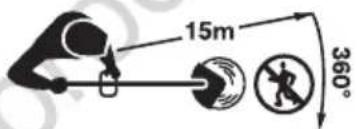
All bystanders must be kept at least 15 m from the machine.

Protect the machine from rain and damp.
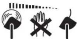
Tool continues to run some seconds after switching off motor.

Be careful of objects being thrown out!

CAUTION: Hot machine parts. Keep your distance.
- Read the instructions carefully. Ensure you are familiar with all controls & safety precautions outlined in this document before operating the machine.
- Stay alert and watch what you are doing when operating the machine. Do not operate the trimmer under the influence of alcohol, drugs or medication or when you are tired or sick.
- Operate the trimmer at reasonable hours only - not early in the morning or late at night or when people might be disturbed. Check with your local council for operation times.
- Do not operate the trimmer indoors or in confined spaces.
- While the trimmer is running, always keep hands and feet away from the trimmer head. (Keep away from any bystanders or animals when in use.)
- Use only manufacturer's genuine recommended replacement parts and accessories.
Table of Contents
 | Quick Start | ||
| Quick Start | 1 | ||
 | Features & Definitions | ||
| Features Definitions | 2 | ||
 | Safety & Handling | ||
| Safety Instructions | 4 | ||
| Safety Hazards | 6 | ||
| Personal Safety Equipment | 6 | ||
| Assembly Procedures | |||
 | Handle Assembly | 7 | |
| Carry Strap Assembly | 7 | ||
| Guard Assembly | 7 | ||
| Shaft Assembly | 8 | ||
| Trimmer Line Assy. (Bump Head) | 9 | ||
| Trimmer Line Assy. (Alloy Head) | 11 | ||
| Cutting Head Assembly | 12 | ||
 | Operating Instructions | ||
| Before Starting | 13 | ||
| Fuelling Procedures | 13 | ||
| Starting Instructions | 14 | ||
| Stopping Instructions | 15 | ||
| Feeding Bump Head | 15 | ||
| Trimming Tips | 15 | ||
 | Maintenance & Care | ||
| Air Filter | 17 | ||
| Spark Plug | 18 | ||
| Storage | 18 | ||
| Maintenance Chart | 19 | ||
 | Troubleshooting | ||
| Troubleshooting | 20 | ||
NOTE: WARRANTY DETAILS ARE NOT WRITTEN WITHIN THIS OPERATOR'S MANUAL. REFER TO OTHER DOCUMENTS SUPPLIED WITH THIS MACHINE FOR WARRANTY DETAILS.
NOTE: THE WARRANTY DOCUMENTS MAY INCLUDE TECHNICAL SPECIFICATIONS THAT ARE SPECIFIC TO EACH MODEL THAT ARE NOT WRITTEN WITHIN THIS OPERATOR'S MANUAL.
Quick Start Guide

Check the position & operation of controls to ensure you are comfortable before you start using the machine.

Check all components are assembled as per assembly instructions on page 7.

Check
• That there are no leaks in the fuel system
• That all screws are securely fastened
- Trimmer Bump Head, Guard and Coupling are secured safely and as instructed.
Quick Start Guide
1 - Get ready...
- Place the trimmer on a hard, level surface.
- Press the PRIMER 10 times.

2 - Set
- Set STOP switch to the "ON" position (I)
- Set the choke lever to COLD

natural_image
Close-up of a mechanical component with directional arrows indicating movement or change (no text or symbols)3 - Go!
- Slightly pull out the starter cord until you feel it resist
- Then tug sharply on the starter cord 2 or 3 times or until the engine starts. This should start your trimmer.
- Reset the choke lever to HOT position.

natural_image
Close-up of a mechanical device with a black arrow pointing to a component, labeled '3.' (no readable text or symbols beyond label)
Never allow the starter cord to snap back. This may damage the machine!
Bent Shaft Trimmer
1 Upper Shaft
2 Shoulder Strap
3 Universal Handle
4 Trimmer Guard
5 Bent Lower Shaft
6 Spark Plug Wrench
7 Allen Key
8 Allen Key
9 Reversible Screw Driver
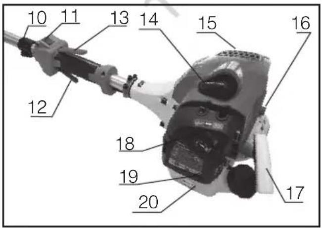
10 Hook, Shoulder Strap
11 Engine Stop Switch
12 Throttle Lever
13 Presence Release
14 Spark Plug Boot
15 Engine Shroud Cowling
16 Fuel Primer Pump
17 Starter Chord Lever
18 Choke Lever
19 Air Filter Housing Cover
20 Petrol Tank
21 Shaft Coupling
22 Trimmer Line - Bump Head



Do not operate the VICTA Trimmer before reading all Safety & Handling sections.
Straight Shaft Trimmer
1 Upper Shaft
2 Shoulder Strap
3 Universal Handle
4 Trimmer Guard
5 Straight Lower Shaft
6 Spark Plug Wrench
7 Allen Key
8 Allen Key
9 Reversible Screw Driver
10 Hook, Shoulder Strap
11 Engine Stop Switch
12 Throttle Lever
13 Presence Release
14 Spark Plug Boot
15 Engine Shroud Cowling
16 Fuel Primer Pump
17 Starter Chord Lever
18 Choke Lever
19 Air Filter Housing Cover
20 Petrol Tank
21 Shaft Coupling
22 Trimmer Line - Bump Head
23 Bracket, Trimmer Guard


Safety Instructions

Do not operate the VICTA Trimmer before reading all Instructions & reading all Safety & Handling sections.
Operator Safety
- Wear the necessary safety equipment, as listed on page (6), in the Personal Safety Equipment Section.
- Always wear heavy, long pants. Do not wear loose clothing, jewellery, short pants, sandals or go barefoot. Secure hair so it is above shoulder length.
- Do not operate the unit if you are tired, ill or under the influence of alcohol, drugs or medication.
Unit Safety
- The product is intended for garden maintenance trimming of organic ground covering such as grass and lawn. The product must not be used for or modified for uses other than is intended, unless approved by the manufacturer.
- Inspect the entire unit and cutting head before each use.
- Ensure that the guard is properly attached.
- Do not use the unit if it is running erratically. Have it serviced promptly.
- Keep handles free of oil and fuel.
- Learn how to stop the engine quickly in an emergency.
- Stop the engine when the unit is unattended. Never leave engine running while unattended.
- Never allow children or unauthorised persons to operate the unit.
- Do not leave the unit on dry cuttings when it is Hot, as a risk of fire is present. Do not cover muffler or restrict airflow to muffler..
Fuel Safety
- Use a container approved for fuel and a funnel to avoid spillage.
- Mix and pour fuel outdoors where there are no sparks or flames.
• Frequently check for fuel leaks. - Do not smoke or allow smoking near fuel, or near the unit, or while using the unit.
- Add fuel before starting the unit.
- Never remove the fuel tank cap while the engine is running or hot, allow to cool before refuelling.
- Never allow the unit to run out of fuel before refuelling.
- Move at least 3 metres away from the fuelling site before starting the engine.
- Wipe all traces of fuel on the unit before starting the engine.
- Change your clothes before starting the unit if fuel has been spilt on them.
Safety Instructions
Starting Safety
- Start the engine with feet well away from the cutting head.
- Ensure that the area of starting and operation is clear of sticks, stones, glass, nails, wire, string and debris, which could be thrown by the cutting head.
Cutting Safety
• Use only in good visibility and favourable weather conditions.
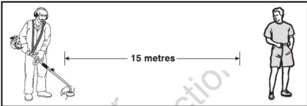
- Keep children, animals and bystanders outside the 15 metre hazard zone. Stop the engine immediately if approached.
- Keep the engine to the right of your body, holding the unit with both hands.
- Keep a firm footing and balance. Do not over reach.
- Keep the cutting head below waist level and do not raise the engine above your shoulder. The cutting head can come dangerously close to your body.
- Keep your body away from the cutting head and muffler when the unit is running.
- Do not strike objects that may cause harm or damage to the unit.
Maintenance Safety
- Stop the engine and disconnect the spark plug before clearing blockages, checking or working on the unit. Clean carbon from the muffler at exhaust outlet frequently.
- Stop the engine, disconnect the spark plug and inspect the unit if it begins to vibrate abnormally or if it strikes a foreign object.
- Use only trimmer line with diameter of 2.0mm to 3.0mm. Never use wire, rope, string, cutting disc etc.
• Use only genuine VICTA replacement parts.
Transporting and Storage
- Hand carry the unit with the engine stopped and the muffler away from your body.
- Allow the engine to cool, empty the fuel tank and secure the unit before storing or transporting in a vehicle.
• Empty the fuel tank after each use and before storing the unit. - Store the unit and fuel well away from sparks or open flames from water heaters, electric motors, switches or furnaces, etc.
• Store the unit out of reach of children and unauthorised persons.
Safety Hazards
The following safety precautions must be strictly observed to avoid the risk of damage or personal injury.

Prior to using the unit, clear the operating area of objects which may be thrown up by the cutting head, such as rocks, glass and other debris.

Do not start or operate the unit inside a closed room or building. Breathing exhaust fumes can kill.

Be careful when operating the unit on slippery ground or overgrown terrain. Be attentive for concealed hazards, such as ditches, tree stumps and roots.

Maintain solid footing and balance while operating the unit. Cut only on ground level.

Never use the unit without the guard securely in place.

Do not touch the cutting head in motion. When handling blade for assembly or maintenance tasks, always wear protective gloves.

Bystanders must be at least 15 metres away during operation of the unit, as rocks and other materials may be thrown at high velocities. Switch the unit off immediately if approached.

Keep body away from hot muffler parts.
Personal Safety Equipment
Always use the following safety equipment when working with your trimmer:
- A safety helmet fitted with a visor or suitable eye protection.
- A set of ear muffs.
• A pair of protective gloves.
• A pair of safety boots.



ASSEMBLY PROCEDURES
Handle Assembly
Fitting the handle
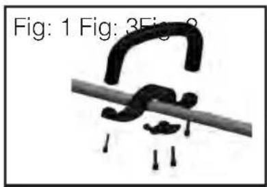
- Remove all the screws from the handle. (Fig.1)
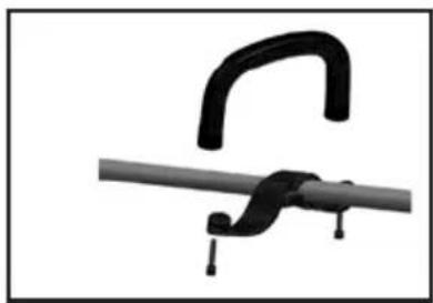
- Position brackets on Upper Shaft and secure screws.(Fig.2)
- Position Top handle onto bracket and secure two screws. (Fig.3)
natural_image
Close-up of a black curved clamp attached to a gray rod, with no visible text or symbols.
natural_image
Close-up of a black plastic clamp securing a gray rod (no text or symbols visible)CAUTION! Not too loose or too tight. Over tightening may damage the unit.
Carry Strap Harness Assembly
Fitting the Carrying Strap Harness
- The strap is intended to help you work safely & ergonomically with the machine.
- Hook the strap into the fastening eyelet.
- Slip the strap over the shoulder.
- Set the length of the shoulder strap in such a way that the trimmer head runs parallel to the ground. In order to establish the optimum length of the strap, you should then make a few swinging movements to check operating comfort before starting the engine.

natural_image
Close-up of a hand holding a metallic cylindrical tool with a black clip, showing a white arrow pointing to the handle (no text or symbols visible)
natural_image
Illustration of a person using a long-handled tool to brush through tall grass (no text or symbols)Guard Assembly
Fitting the bent shaft guard
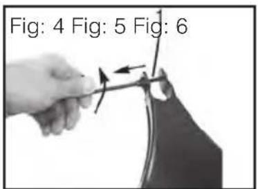
- Remove screw from guard using an Allen key (Fig 4).
- Clip the guard to the lower bent shaft head spindle and ensure is seated in location (Fig 5).
natural_image
Close-up of a curved mechanical component with an arrow indicating motion (no visible text or symbols)
natural_image
Close-up of hands using a tool to adjust or install a mechanical component (no visible text or symbols)Guard Assembly
Fitting the straight shaft guard
- Remove two screws from guard (Fig 7).
- Position guard under the securing saddle (Fig 8).
- Secure the two screws into the guard (Fig 9).

natural_image
Black plastic mechanical component with rounded edges and a small protrusion (no text or symbols visible)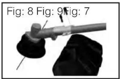

natural_image
Mechanical assembly diagram showing a lever and base component (no text or symbols)
Do not use the trimmer without the guard.
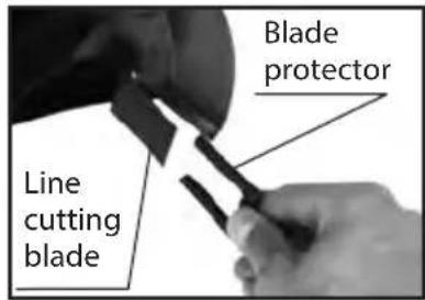
Always ensure the line cutting blade on the guard is covered with the blade protector when fitting, changing or removing the trimmer guard.
Shaft Assembly
Assembling the Split Shaft
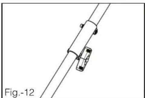
- Loosen the knob (3) on the split shaft coupling (1). Refer Fig.-10.
- Then push the pin (4) on the attachment shaft (2) inwards and carefully slide the attachment shaft in the coupling.
Note: When inserting attachment shaft into the coupling, shifting of the shaft alignment by slight rotation of the cutting head may assist with smoother engagement.
- Ensure that the pin (2) on the attachment shaft locks into the corresponding hole on the coupling.
- Then firmly re-tighten the knob (3).
- To disassemble, reverse order of assembly.



Locking the pin (2) into the shaft hole (5) ensures full engagement of drive shafts. Failure to fully engage drive shafts will damage the connection & void product warranty. (Fig.11).

Do not Start or Run powerhead unit without shafts & guards fully assembled.
Take care when fitting & tightening. Beware of pinch points.
natural_image
Diagram of a mechanical assembly with two car bodies and a cylindrical component, labeled Fig.-12 (no text or symbols on the diagram itself)Trimmer Line Assembly - Bump Head

natural_image
Close-up of a hand pressing a black button on a black surface (no visible text or symbols)

natural_image
Close-up of a mechanical component with a circular top and flanged side, attached to a wire (no visible text or symbols)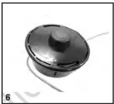
natural_image
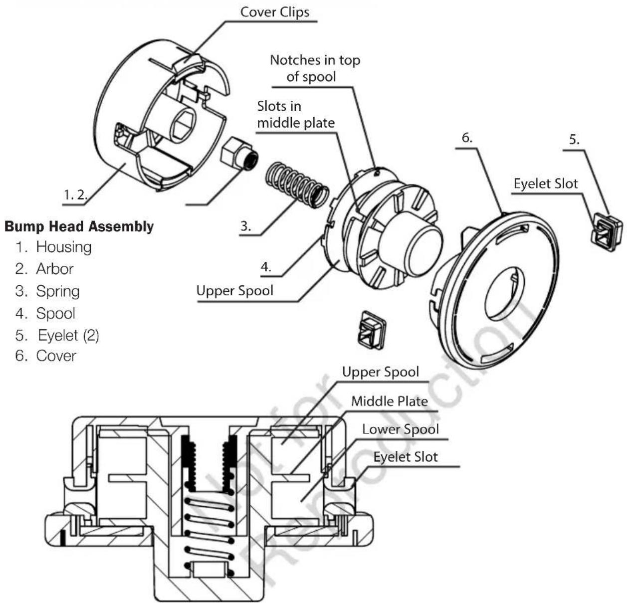
Close-up of a metallic circular component with a central knob, possibly a fan or lid, against a plain background (no text or symbols visible)- Press two cover clips inwards on the housing & remove the cover slowly.
- Remove the remains of worn line from the spool (if any remains).
Note: Remaining line may be sufficient to rewind and reuse if it has been tangled or has retracted back into the housing.
Note: Ensure inside of housing and spool are clean and free of grass & soil before refilling.
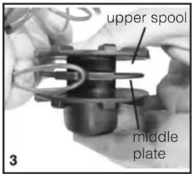
- Use 6 meters of diameter 2.4mm nylon line*. Fold the full length of line in the center and insert the centre fold into one of the slots in the spool middle plate.
- For Straight Shaft Trimmer: Wind the upper half of the line tightly 'CLOCKWISE' onto the upper spool.
Note: 'CLOCKWISE' direction when looking at the top of the spool as shown by the arrow in Fig.4.
- For Bent Shaft Trimmer: Follow the same process as listed in point 4, but in 'ANTICLOCKWISE' direction.
- Continue winding until approximately 10cm remains at the end of the line and hold line end by locking into one of the four notches on the top of the spool. Refer Fig. 4.
- Repeat process with other half of the line winding in the SAME DIRECTION on the lower spool and hold the line end in an opposite notch.
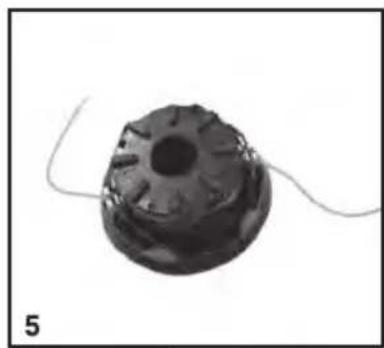
- Put the spool back into the cover. Remove one end of the line from the spool notch & push it into an Eyelet slot. Repeat for the other end of the line into the opposing Eyelet slot. Pull both ends of line tightly through the eyelets to remove any excess slack in spool winding.
- Push the spool and cover back into the housing so that the housing clips align with the cover and clicks back into place.
* 2.4mmø nylon line is recommended to provide best performance. The bump head can be fitted with line diameters from 2.0mm to 3.0mm. The maximum length of the line that can fit the head varies according to the line diameter. The maximum length capacity using 2.4mmø is 6 metres. Do not overfill the head spool with excessive lengths of line as it will result in ineffective spool feeding of line.
Trimmer Line Assembly - Bump Head
Follow the Operating Instructions on page (9) to adjust the length of the line.

Nylon line will deteriorate over time and may require replacement if line breakages and cut performance is not satisfactory
Do not operate the bump head with parts missing such as the spring or eyelets
Do not operate the bump head if the cover is not secured by the Cover Clips.

Do not operate the bump head if components are damaged or excessively worn.
Always ensure the line cutting blade on the guard is covered with the blade protector when fitting, changing or removing the bump head.

perate the machine without a cutting head fitted. Never fit an alternative head that has not been recommended by the manufacturer.
Trimmer Line Assembly - Cast Alloy Head
Note: Not provided in the package. Cast alloy head is available as an accessory with some models at Victa authorized dealers.

- Cut a length of line to 44cm, or use Victa part number TR00200A. Bend line in half at the centre (equal ends). Use only 3mm diameter Nylon line (Fig: 1)
- Push the bent end of the line under the lug of the trimmer head
- Push one end of the line into the hole on the same side of the head as the line end. Pull the line through the hole until loops or slack between the hole centre lug is removed.
- Repeat step 3 for opposite side.
- Refer to image for correct complete assembly of the nylon line into the head.
- To remove used line, bend new line as in (1), slide new line under used line through slot in cast head.
- Holding both ends of the new line together, pull the old line out of the cast head. Repeat process for the other side (8).

Only use genuine VICTA 3mm diameter nylon trimmer line in the Cast Alloy Head.
Unequal lengths of line, or mounting of line "off-centre" will cause vibration & damage to unit.

Excessive trimmer line length will damage guard and clutch or tangle in head gearbox. Do not fill head with excessive length line longer than limits of the guards.

Replace line when worn to approximately 50mm from trimmer head body. Remove line by pushing length back into head or by levering out from centre.
Nylon line will deteriorate over time and may require replacement if line breakages, line wear & cut performance is not satisfactory.
Cutting Head Assembly

Always ensure the line cutting blade on the guard is covered with the blade protector when fitting, changing or removing the trimmer head.
Always disconnect the spark plug lead before and work is done on the trimmer.

Never operate the machine without a cutting head fitted.
Never fit an alternative cutting head that has not been recommended by the manufacturer.
CUTTING HEAD REMOVAL & REPLACEMENT
BENT SHAFT CUTTING HEAD
- Cover the cutting blade with protector.
- Align hole in Gearbox Mounting & slot on the shaft.
- Insert Allen Key into hole & firmly support to lock shaft rotation.
- Grip the head & rotate anti-clockwise to remove.
- Refit preferred head in reverse order & firmly tighten.

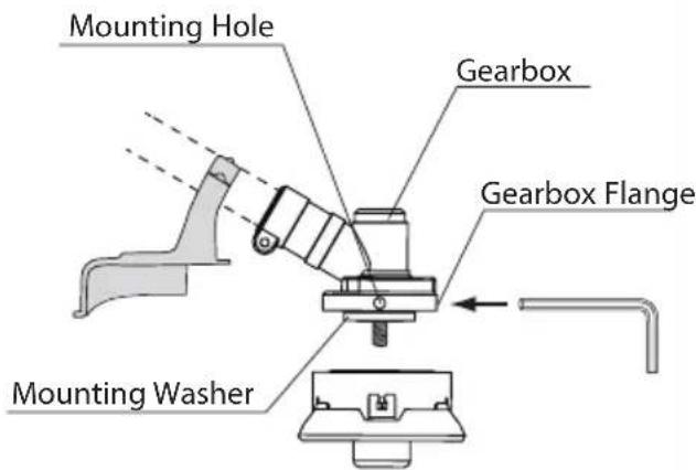
STRAIGHT SHAFT CUTTING HEAD
- Cover the cutting blade with protector.
- Align hole in Mounting Washer and Gearbox slot.
- Insert Allen Key through hole in Gearbox Flange, through hole in Mounting Washer. Firmly support Allen key to lock shaft rotation.
- Grip the head & rotate clockwise to remove.
- Refit preferred head in reverse order & firmly tighten.

It is important to note the direction of rotation to tighten/remove heads & to avoid over-tightening or damage to the Gearbox, Spindle or mounting thread.
Not firmly supporting alignment locking of shaft with the Allen Key may cause damage to the Gearbox or Mounting Washer.
OPERATING INSTRUCTIONS
Before Starting

Check the position & operation of controls to ensure you are comfortable before you start using the machine. Triggers, starter cord and grip position should provide smooth operation, balance and comfort before starting the machine. Check that all screws are securely fastened and also check all the safety devices.

Always use the shoulder strap when using the machine. Switch off the engine before you take off the shoulder strap.
Check the machine for the following each time before use:
• That there are no leaks in the fuel system
• That the cutting unit and all safety devices are in perfect condition
• That all screws are securely fastened
Fuelling Procedures
Recommended fuels
- Use only a mixture of normal unleaded petrol and 2-stroke engine oil. Mix the fuel mixture as indicated on the fuel mixing table.
- Start the machine at least 3 metre away from the refuelling site to avoid the possible risk of fire.
- Do not smoke whilst refuelling or working with the machine.
- Do not use the trimmer near inflammable liquids or gases. This could result in an explosion and/or fire.
- Pour the correct quantities of petrol and 2-stroke oil into a container. Then shake the container well.
NOTE: Product may need to be reprimed if it has run out of fuel.

Victa recommends the use of Victa Formula V 2-stroke oil at 50:1 fuel to oil ratio only.
The use of other oils and or ratios will affect the engine lubrication, which may cause engine damage and void engine manufacturer's warranty.

Do not use a fuel mixture which has been kept for longer than 90 days. It may damage the unit.
Only use containers designed and approved for the purpose to transport and store fuel.
Fuel Mixture Table
| Petrol (unleaded) 2-stroke oil | |
| 5 litre 100 ml (Only for Victa Formula V 2-stroke Oil) | |
| Mixing procedure: 50 parts unleaded petrol to 1 part 2-stroke oil | |
| USE Clean fresh "Regular Unleaded Fuel"Fuel with up to 10% ethanol can be used |
Starting Instructions
Cold Start
- Set the machine down on a hard, level surface.
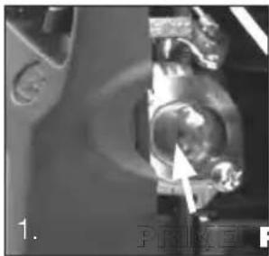
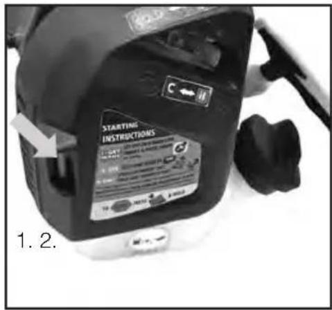
- Press the fuel pump primer 10 times. This is found behind the air filter housing (see Fig. 1).
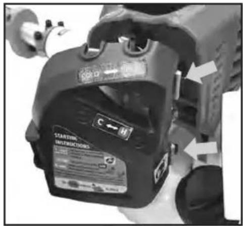
- Ensure the 'STOP SWITCH' is set to the 'ON' position (I) as shown in Fig. 2.
- Set the choke lever to the 'COLD' position, (see Fig. 3).
- Pull out the starter cord until you feel it start to resist. Then tug sharply on the starter cord 2 or 3 times or until the engine tries to start.
- This should start the engine. While the engine is running, move the choke to the 'HOT' position (see Fig 4).
Hot Start
- Set the machine down on a hard, level surface.
- Ensure the 'STOP SWITCH' is set to the 'ON' position (I) (see Fig 2).
- Ensure the choke lever is set to the HOT position, (see Fig 4).
- Pull out the starter cord until you feel it start to resist. Then tug sharply on the starter cord 2 or 3 times or until the engine tries to start.
- If the engine fails to start, retry the "COLD" start Procedure or refer to the troubleshooting section.
natural_image
Close-up of a mechanical component with a white arrow pointing to a circular feature (no visible text or symbols)
natural_image
Close-up of a mechanical connector or plug with a metallic tip and internal components (no visible text or symbols)
natural_image
Close-up of a metallic mechanical component with a black arrow pointing to a feature (no text or symbols visible)
natural_image
Close-up of a train's front view showing the nose and side profile, with an arrow pointing to the nose (no text or symbols visible)
Always pull the starter out in a straight line.
IF THIS IS NOT FOLLOWED, STARTER CORD WILL BE FRAYED AND CORD WILL BREAK!
This is not covered by the product Warranty.
Important Notes & Tips
- In cold conditions, the engine may require 5-10 seconds running at idle. Slight intermittent pulling of the throttle trigger may assist during engine warm-up.
- If the engine fails to start, repeat the process from step (4).
- Adjustment of the choke lever between "HOT" and "COLD" position may be required during engine warm-up. Engine warm-up may take several minutes until the engine is running hot and engine speed is stable.
- If the engine slows down or stops, adjusting the choke lever towards the "COLD" position may be required during warm-up. Return the choke lever to the "HOT" position, before proceeding with operating the machine.
- If the engine does not start up after several attempts, read the section on troubleshooting.
OPERATING INSTRUCTIONS
Stopping Instructions
-
To stop the trimmer, release the throttle lever and move the stop switch to 'OFF' position (O).
-
Note the switch will need to be returned to the 'ON' position (I) prior to restarting.
Feeding Bump Head Line
To increase the length of nylon trimming line when using the Bump Head;
- Run the trimmer at maximum RPM while firmly bumping the spool on the ground.
- The line will come out incrementally each time head is bumped.
- Check the length after each bumping and repeat till the required length is achieved.
- Bump and feed the line before it becomes too short and fall back into the bump head. If this happens refer to the section of "Trimmer Line Assembly – bump head" on page 9.
Note: refer to "Troubleshooting - Bump head" if the line is not coming out when bumping.

DO NOT touch the bump head while the engine is running.
DO NOT Bump feed excessive lengths on line longer than the limits of the guards.
Trimming Tips
Practical Tips
- Practice all operating techniques with the engine switched off before you start to use the machine.
- Remove Weed/Grass wrapped around Head/Shaft.
- When properly equipped with a guard and cutting head, your unit will trim unsightly weeds and tall grass in those hard-to-reach areas – along fences, walls, foundations and around trees. It can also be used for scalping to remove vegetation down to the ground for easier preparation of a garden or to clean out a particular area.

DO NOT use steel wire or plastic-coated steel wire of any kind with your string head. Serious operator injury can result.

Periodically remove weed wrap to prevent overheating the drive shaft. Weed wrap occurs when strands of weed become entangled around the shaft beneath the debris shield. This condition prevents the shaft from being properly cooled.
Trimming around foundations, brick or stone walls, curves etc. will result in above normal string wear.
Trimming Tips Cont.
Trimming / Mowing
- Swing trimmer with a sickle-like motion from side to side. Do not tilt the cutting head during the procedure. Test area to be trimmed for proper cutting height. Keep string head at same level for even depth of cut.
Fence / Foundation Trimming
- Approach trimming around chain link fences, picket fences, rock walls and foundations slowly to cut close without whipping string against the barrier. If the string comes in contact with rock, brick walls, or foundations, it will break or fray. If string snags fencing, it will snap off.

natural_image
Diagram of a spray gun spraying water with arrows indicating flow direction (no text or symbols)Trimming Around Trees
- Trim around tree trunks with a slow approach so string does not contact bark. Walk around the tree trimming from left to right. Approach grass or weeds with the tip of the string and tilt cutting head slightly forward.

natural_image
Illustration of a broom with a handle and spout, against a textured background (no text or symbols)Scalping
- Scalping refers to removal of all vegetation down to the ground. To do this, tilt the cutting head to about 30 degree angle to the left. By adjusting the handle you will have better control during this operation. Do not attempt this procedure if there is any chance flying debris could injure operator, other people or cause damage to property.

Use extreme caution when SCALPING. Keep a distance of 100 feet (30 metres) between operator, other people and animals during these operations.
Maintenance - Air Filter
Maintenance of the air filter
Always switch off the machine and pull out of spark plug H.T. lead before carrying out any maintenance work.

natural_image
Close-up of a mechanical device with black components and a white housing (no visible text or symbols)
natural_image
Close-up of a mechanical component with a black arrow pointing to a dark square object, labeled '4.' (no text or symbols on the object itself)NOTE: Dirty air filters reduce the engine output by supply too little air to the carburettor.
Regular checks of the air filter is essential. The air filter should be checked monthly and cleaned if necessary. The air filter should be checked more frequently when used in dry and dusty environments.
-
Remove the air filter cover
-
Remove the filter element
-
Clean the filter element by washing in soapy water and allowing it to dry completely.
-
Soak in 2 stroke oil and squeeze off excess.
-
Assemble in reverse order.

Never clean the air filter with petrol or inflammable solvents.

Make sure Air Filter is fitted correctly, (warranty will be void if engine is damaged due to incorrect fitment)
Maintenance - Spark Plug
CHAMPION # RCJ7Y BOSCH # WSR6F NGK # BPMR7A VICTA # HA25735A
Your trimmer may be fitted with a CHAMPION or NGK spark plug.

Spark plug gap = 0.025 inch (0.7 mm).
Tighten the spark plug with a torque of 12-15 Nm.
Check the spark plug for dirt and grime after 10 hours of operation and if necessary clean.
Thereafter service the spark plug after every 50 hours of operation.
-
Pull off the spark plug boot by twisting side to side gently. (Fig 1)
-
Remove the spark plug with a spark plug tube spanner. (Fig 2)
-
Assemble in reverse order.

natural_image
Close-up of a gloved hand adjusting a mechanical component with directional arrows (no visible text or symbols)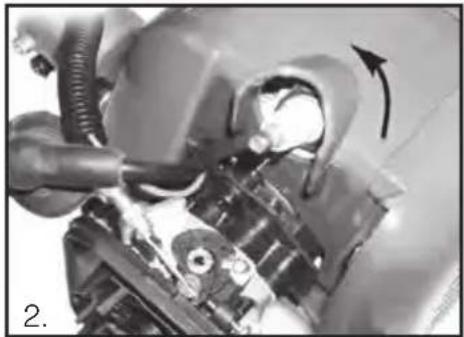
natural_image
Close-up mechanical assembly showing a valve and housing with an arrow indicating direction (no visible text or symbols)Storage

If you fail to follow these instructions correctly before storing the machine, deposits may form on the interior of the carburettor & may result in the engine being more difficult to start or the machine suffering permanent damage.
Storage Preparation
- Carry out all the maintenance work require prior to storing.
- Drain the fuel out of the tank.
- When the fuel has been drained, start the engine.
- Allow the engine to run at idling speed until it stops. This will clean the remainder of the fuel out of the carburettor.
- Leave the machine to cool (approx. 5 minutes).
- Remove the spark plug.
- Place a teaspoon full of 2-stroke engine oil into the combustion chamber. Pull the starter cable several times carefully to wet the internal components with the oil. Refit the spark plug.
- Clean the exterior housing of the machine.
9 Store the machine in a cold, dry place where it is out of the reach of ignition sources & inflammable substances.
Fertilizers and other chemical garden products often contain substances that accelerate the rate of corrosion of metals. Do not store the machine on or near fertilizers or other chemicals.
Before restarting
Remove the spark plug & pull the starter cord several times to clean & pour the oil out of the combustion chamber. Clean the spark plug contacts or fit a new spark plug.
Transport
To transport the machine, first empty the petrol tank. Pump the primer to completely remove fuel from the carburettor & empty excess from the tank.
Clean coarse dirt off the machine with a brush.
Dismantle the split shaft as described (pg.8) if preferred.
Maintenance Chart
| Features Requirements | Before | After finish | Refuelling | Monthly | Yearly | If damaged | As required | |
| Trimmer | Visual inspection (leaks) | ● | ● | |||||
| Throttle lever | Check operation | ● | ||||||
| Throttle trigger interlock | Check | ● | ||||||
| Stop switch | Check | ● | ||||||
| Fuel tank | Clean | ● | ||||||
| Cutting Head Assy | Check & clean | ● | ● | |||||
| Gearbox | Grease (straight shaft) | ● | ● | |||||
| Air filter | Check | ● | ||||||
| Clean | ● | ● | ||||||
| Replace (Depending on conditions) | ● | ● | ||||||
| Cowling | Clean | ● | ||||||
| Cylinder fins | Clean | ● | ||||||
| Spark plug | Clean & readjust gap | ● | ● | |||||
| Nylon Line | Stock replacement | ● | ● | |||||
| Bump Head | Inspect | ● | ● | ● | ||||
| Cast Trimmer Head | Clean | ● | ||||||
| Replacement | ● | ● | ||||||
| All accessible fasteners | Retighten | ● | ● | |||||
| Muffler | Inspect | ● | ● | |||||
| Inspect spark arresting screen | ● | ● | ||||||
| Clean or replace | ● | ● | ||||||

Always stop the engine before any maintenance is done on the unit. When all parts have stopped rotating, remove the spark plug lead to begin maintenance work.

Never repair cutting attachments by welding, straightening or custom reworking of parts. This may result in product failure or serious injury.

Never attempt maintenance that is not outlined in this manual. All repair work must be carried out by a VICTA Authorised Service Centre.
Troubleshooting
| Problem Possible cause Remedy | ||
| Engine will not start | Electrode is wet or fouled Dry spark plug or replace | |
| Carbon deposit on electrode Clean spark plug | ||
| Spark plug (no spark) | Cracked insulator | Replace spark plug |
| STOP SWITCH in OFF position | Switch to ON | |
| Too small or large electrode gap Adjust gap to 0.7mm (0.025°) | ||
| Burned electrode Replace spark plug | ||
| Ignition system (no spark) | Coil burned out, coil insulation failure | Contact Service Centre |
| Break in coil wire, transistor burned out | Contact Service Centre | |
| Engine won't start - Good compression, sufficient fuel (with spark) | Engine flooded Crank engine choke off to discharge fuel | |
| Excessively thick fuel Contact Service Centre | ||
| Use of incorrect fuel Drain and replace with correct fuel | ||
| Poor compression, sufficient fuel (with spark) | Excessive wear on cylinder, piston, rings | Contact Service Centre |
| Loose spark plug Tighten spark plug | ||
| No fuel in carburettor (with spark) | No fuel in tank Refuel | |
| Loose fuel line fitting Contact Service Centre | ||
| Clogged fuel line Contact Service Centre | ||
| Plugged air vent in fuel tank Clean vent/Contact Service Centre | ||
| Insufficient power | Clogged air filter | Clean |
| Blockages | Carbon build up in muffler | Contact Service Centre |
| Fuel line/passage clogged | Contact Service Centre | |
| Piston seizure, diaphragm inoperative | Contact Service Centre | |
| Water in fuel | Contact Service Centre | |
| Overheating | Excessively lean fuel mixture Contact Service Centre | |
| Carbon deposits on piston | Contact Service Centre | |
| Improper fuel mixing ratio | Replace with correct 25:1 fuel mix | |
| Machine is overworked | Operate properly-do not overload | |
| Fan cover, cylinder fins, etc. dirty | Clean and remove dirt and debris | |
| Engine makes knocking noise | Cylinder overheating | Clean fins |
| Use of incorrect fuel Replace with correct fuel | ||
Troubleshooting
| Problem Possible cause Remedy | ||
| Poor acceleration | Fuel filter clogged Contact Service | Centre |
| Fuel system clogged | Excessively low idle Speed up idle/Contact Service setting | Centre |
| Excessively lean carburettor setting | Contact Service Centre | |
| Air leakage | Clogged air filter Clean filter | Centre |
| Loose carburettor Contact Service | Centre | |
| Loose fuel pick up tube Insert firmly/Contact Service Centre | ||
| Engine stops during operation | Switch is bumped Keep hands clear of switch | |
| Engine stops abruptly | Shorting of spark plug Clean spark plug | |
| Piston scored, ignition failure Contact Service Centre | ||
| Miscellaneous | Fuel tank empty Refuel | |
| Carburettor or fuel tank clogged Contact Service Centre | ||
| Engine is difficult to shut off | Overheated engine Run at idle | |
| Overheating or electrical fault | Overheated spark plug | Clean and adjust gap to 0.7mm (0.25") |
| Defective kill switch | Contact Service Centre | |
| Poor contact of ground wire | Contact Service Centre | |
| Unit main body | Loose trimmer head | Tighten firmly |
| Irregular vibration or trimmer head spins with engine idling | Broken clutch spring, bent main shaft | Contact Service Centre |
| Worn shaft bearings | Contact Service Centre | |
| Loose gear head | Tighten bolt securely/Contact Service Centre | |
| Bump head: | Inappropriate winding of line. | Open bump head and rewind the line ("Fitting trimmer line - bump head" on page 9) |
| Line doesn't come out when head is bumped | Line inside bump head is nearly finished. | Replace the residual line with the new line ("Fitting trimmer line - bump head" on page 9) |
If running difficulties continue, contact your closest VICTA Authorised Service Centre in Australia and New Zealand. Please look up and locate your local Authorised Service Centre on www.victa.com or contact Victa Lawncare Customer Service. Refer to the warranty card for the contact details.
©2021 Briggs & Stratton LLC
Victa is a trademark of Briggs & Stratton Australia Pty Ltd
ABN 13 006 576 856
All rights reserved. No part of this booklet may be reproduced by any means without prior written permission. All information herein is subject to change without notice.
WWW.VICTA.COM



- Line Trimmer Assembly and Owner's Manual
- IMPORTANT NOTES
- Please read the following
- Safety Markings and Symbols
- Quick Start Guide
- Check
- - Get ready...
- - Set
- - Go!
- Bent Shaft Trimmer
- Straight Shaft Trimmer
- Safety Instructions
- Do not operate the VICTA Trimmer before reading all Instructions & reading all Safety & Handling sections.
- Operator Safety
- Unit Safety
- Fuel Safety
- Starting Safety
- Cutting Safety
- Maintenance Safety
- Transporting and Storage
- Safety Hazards
- Personal Safety Equipment
- ASSEMBLY PROCEDURES
- Handle Assembly
- Fitting the handle
- Carry Strap Harness Assembly
- Fitting the Carrying Strap Harness
- Guard Assembly
- Fitting the bent shaft guard
- Fitting the straight shaft guard
- Shaft Assembly
- Assembling the Split Shaft
- Trimmer Line Assembly - Bump Head
- Trimmer Line Assembly - Cast Alloy Head
- Cutting Head Assembly
- CUTTING HEAD REMOVAL & REPLACEMENT
- BENT SHAFT CUTTING HEAD
- STRAIGHT SHAFT CUTTING HEAD
- OPERATING INSTRUCTIONS
- Before Starting
- Fuelling Procedures
- Recommended fuels
- Fuel Mixture Table
- Starting Instructions
- Cold Start
- Hot Start
- Important Notes & Tips
- Stopping Instructions
- Feeding Bump Head Line
- Trimming Tips
- Practical Tips
- Trimming Tips Cont.
- Trimming / Mowing
- Fence / Foundation Trimming
- Trimming Around Trees
- Scalping
- Maintenance - Air Filter
- Maintenance of the air filter
- NOTE: Dirty air filters reduce the engine output by supply too little air to the carburettor.
- Maintenance - Spark Plug
- Storage
- Storage Preparation
- Before restarting
- Transport
Brand : Victa
Model : 1697384
Category : Hand tool