
Brigadier OABRFNGSS - Heating Omega Altise - Free user manual and instructions
Find the device manual for free Brigadier OABRFNGSS Omega Altise in PDF.


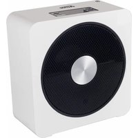
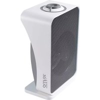
| Product Type | Fan Heater |
| Brand | Omega Altise |
| Model | Brigadier OABRFNGSS |
| Power | 2000 W (adjustable) |
| Heating Settings | Low (1000 W) / High (2000 W) + Thermostat |
| Fan Only Mode | Yes |
| Voltage | 220-240 V, 50 Hz |
| Dimensions (H x W x D) | 25 x 15 x 30 cm |
| Weight | 2.5 kg |
| Noise Level | ~45 dB |
| Recommended Room Size | Up to 20 m² |
| Thermostat | Adjustable (mechanical) |
| Safety Features | Overheat protection, Tip-over switch |
| Finish | White / Grey plastic |
| Power Cord Length | 1.8 m |
| Warranty | 2 years |
| Maintenance | Clean air filter every month; wipe exterior with dry cloth |
| Spare Parts & Repairability | Spare parts available via Omega Altise service; user-replaceable fuse and filter |
Frequently Asked Questions - Brigadier OABRFNGSS Omega Altise
User questions about Brigadier OABRFNGSS Omega Altise
0 question about this device. Answer the ones you know or ask your own.
Ask a new question about this device
Download the instructions for your Heating in PDF format for free! Find your manual Brigadier OABRFNGSS - Omega Altise and take your electronic device back in hand. On this page are published all the documents necessary for the use of your device. Brigadier OABRFNGSS by Omega Altise.
USER MANUAL Brigadier OABRFNGSS Omega Altise
everdure
EVERDURE FINELINE
FLUELESS RADIANT CONVECTION
GAS SPACE HEATER
MODELS
BRIGADIER - 3725, COMMANDER - 3621,
CRUSADER - 3518, LANCER - 2415
Operating and Maintenance Instructions
Australian Made
By
SHRIRO AUSTRALIA PTY. LIMITED
EVERDURE DIVISION.
101 SHEFFIELD ROAD, WELSHPOOL, WESTERN AUSTRALIA
TELEPHONE: 1300 766 066
OFFICE HOURS BETWEEN 8am - 4:30pm WST (Perth)
IMPORTANT
PLEASE READ THESE INSTRUCTIONS CAREFULLY
BEFORE USING YOUR NEW EVERDURE HEATER
EVERDURE MODELS 3725, 3621, 3518, 2415
The Everdure Fineline gas space heaters are described as manually operated, portable, flueless radiant convection heaters for use with Natural gas or Liquid Petroleum gas.
The heater is supplied with an approved flexible hose.
A label is attached to the rear of the heater stating the type of gas for which it has been manufactured and adjusted.
GENERAL REQUIREMENTS
The heater shall be installed in accordance with the manufacturer's instructions, local gas fitting regulations, uniform building regulations, municipal building codes, the AGA installation code for gas burning appliances and equipment and any other relevant statutory regulations.
The heater is intended to be installed as a free standing portable, its portability being restricted by the number of gas outlet points being provided.
The heater must NOT be BUILT IN.
Special room ventilation may apply in your particular state. If in doubt, contact your local gas authority.
Locations where strong draughts occur should be avoided as they may cause unsatisfactory operation of the heater.
The heater should be installed at least 1 metre from flammable materials, e.g. curtains, and to be 150mm clear of sidewalls.
NOTE
This appliance has been fully function tested prior to packaging.
No adjustment is required or available to the user.
No installation is required apart from connection to gas and electrical supplies. (Fig. 1)
MODEL BRIGADIER 3725
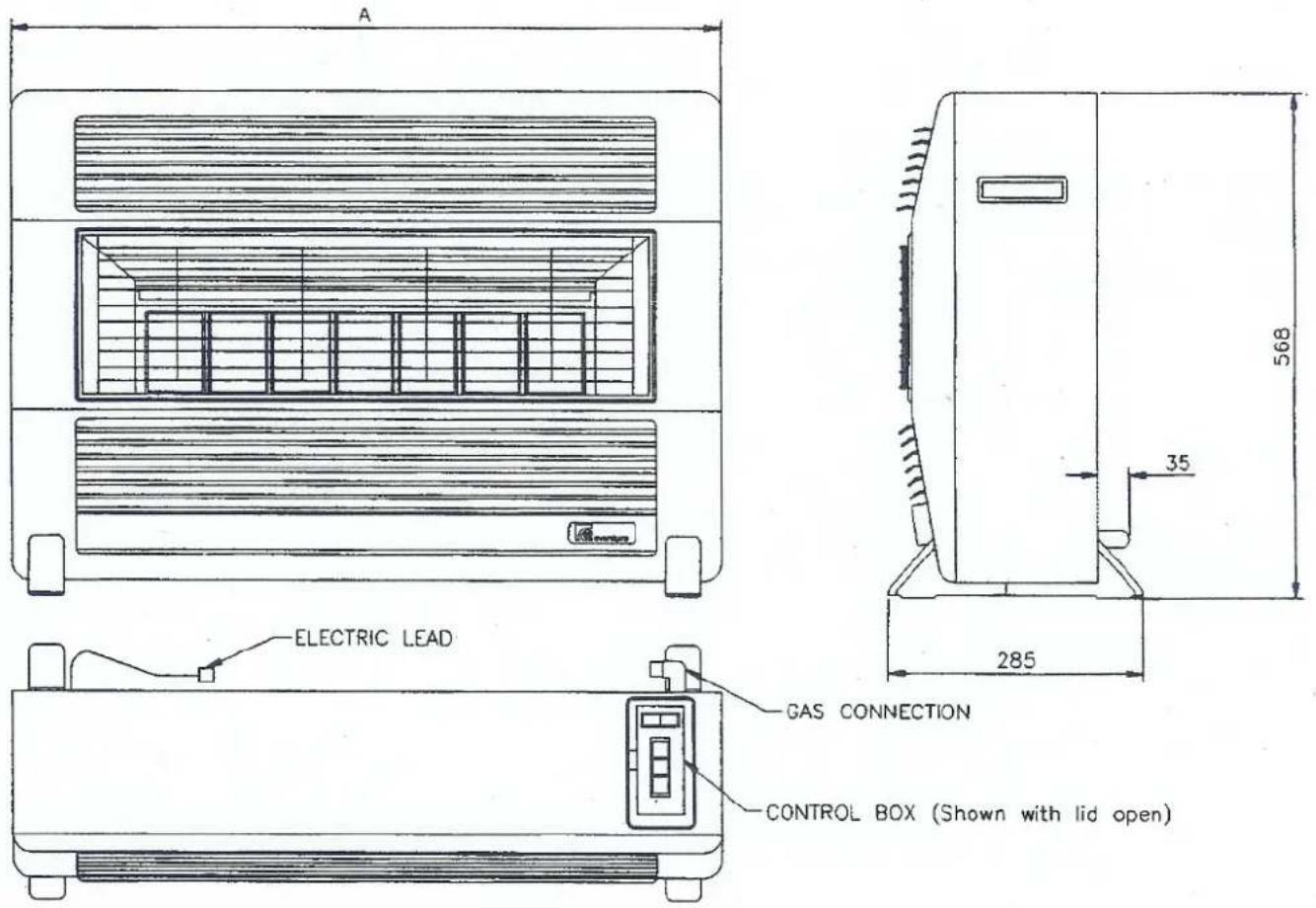
| MODEL | ‘A’ | NUMBER OF TILES |
| BRIGADIER | 796 | 7 |
| COMMANDER | 732 | 6 |
| CRUSADER | 668 | 5 |
| LANCER | 604 | 4 |
Fig. 1
DATA LABEL
The Data Label, as shown below, is located on the inside of the appliance and can be accessed by opening the lower louvre panel. (Fig. 2, Page 7). (Brigadier model shown).
| Everdure Model 3725 | |||
| Gas Type | N.G. | L.P.G. | |
| Nom Gas Consumption | Mj/Hr | 25 | 25 |
| Test Point Pressure | KPa | 0.95 | 2.75 |
| Main Burner Injector | mm | 0.86 | 0.51 |
| Pilot Injector | mm | 0.5 | 0.2 |
| Serial Number | |||
| A.G.A. Certification No. 4918 | |||
OPERATING INSTRUCTIONS
GAS SUPPLY
Your heater is fitted with a flexible hose and bayonet coupling which enables you to connect or disconnect it from the gas supply.
TO CONNECT
Insert the coupling end into the wall socket firmly and rotate the knurled section clockwise to it's locked position.
TO DISCONNECT
Apply firm forward pressure to the knurled area, rotate anti clockwise and pull towards you. The hose should now come away from the wall socket. Gas is automatically isolated when the hose is disconnected.
ELECTRICAL SUPPLY
Your heater is fitted with a power supply lead, which should be connected to a standard domestic socket.
POWER FAILURE
Your Everdure heater will operate quite normally in the event of a power failure. Should the power fail while the heater is operating, the fan will stop. There is however, no need for concern as your heater has been designed to operate satisfactorily with the fan off. (See diagram on next page). Should you wish to ignite your heater during a power failure, follow the instructions under Manual Ignition.
Note: If your heater has been disconnected for some time, there will be air in the flexible hose. It will therefore take a little longer to ignite when you first turn it on.
MANUAL IGNITION
The heater may be manually lit by opening the dress guard (see Cleaning) and while holding down the ignition button, apply a lighted longreach match or taper to the pilot. The ignition button needs to be held down for 20 seconds to allow the valve to lock in. Close up the dress guard as described in the cleaning section.
ABNORMAL OPERATION
As the heater heats up or cools down, expansion or contraction takes place and the occasional ‘click’ may be heard. This is normal, however, continuous metallic noises, grinding sounds, the smell of gas or any of the symptoms listed on the fault finding chart should be investigated immediately. Turn the appliance off and disconnect the gas and electrical supplies. If the fault cannot be fixed or any doubts exist, contact your nearest EVERDURE service agent or contact Everdure on the telephone number on the front cover of this booklet.
CONTROLS
The heating controls and fan switches are located under a lid situated on the top right hand side of the heater. Lighting instructions are affixed to the underside of the lid.
FAN AND FAN SWITCH
The two-speed fan is controlled by the fan switch in the control box, and, as indicated on the control box lid label, the switch has three positions, slow fast and off.
Selection of slow or fast fan speed in conjunction with High, Medium or Low heat settings is determined by personal choice and/or heating requirements at the time.
LIGHTING INSTRUCTIONS
Open the control box lid, depress and hold down the 'ON/IGNITION/LOW' button. This button operates the sparker, which in turn ignites the pilot flame and the low setting burner. It is necessary to hold down the 'ON/IGNITION/LOW' button firmly for at least 20 seconds to allow the gas valve to 'lock in'. If the burner fails to light, repeat the ignition sequence described above.

The ON/IGNITION/LOW button and the MEDIUM/HIGH button each have two operating positions, which provides three heat settings.
IGNITION
Hold down 'ON' button

SWITCH OFF
Depress momentarily
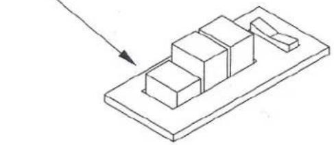
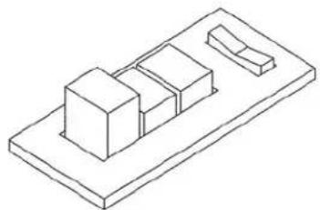
BRIGADIER 3 TILES ON

COMMANDER 2 TILES ON


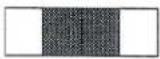
LANCER 2 TILES ON
LOW SETTING
CRUSADER 1 TILE ON

BRIGADIER 5 TILES ON

COMMANDER 4 TILES ON


LANCER : N/A
CRUSADER 3 TILES ON
MEDIUM SETTING

BRIGADIER 7 TILES ON

COMMANDER 6 TILES ON
HIGH SETTING
CRUSADER 5 TILES ON
LANCER 4 TILES ON
Low, medium and high settings can be obtained by setting the buttons set as shown in the diagrams above. If you depress the button firmly and it remains in the half way position, a second depression will return it to the fully up position.
Please Note:
Darkening of the heater tile face is a natural consequence of the gas combustion process.
WARNING
DO NOT place articles on or against this appliance.
DO NOT use or store inflammable materials near this appliance.
DO NOT spray aerosols in the vicinity of this appliance while it is in operation.
DO NOT use this appliance in a marine environment.

DO NOT OPERATE THIS APPLIANCE BEFORE READING THE INSTRUCTION BOOKLET
DO NOT PLACE ARTICLES ON OR AGAINST THIS APPLIANCE
DO NOT STORE CHEMICALS OR FLAMMABLE MATERIALS OR SPRAY AEROSOLS NEAR THIS APPLIANCE
DO NOT OPERATE WITH PANELS, COVERS OR GUARDS REMOVED FROM THIS APPLIANCE
DO NOT OPERATE IN A BATHROOM OR BEDROOM
DO NOT OPERATE IN AN UNVENTILATED ROOM
DO NOT OPERATE IN A ROOM WITH A VOLUME LESS THAN THAT SHOWN IN THE TABLE BELOW
| MIN. ROOM SIZE PER MODEL | |
| MODEL | ROOM VOLUME (N.G or L.P.G) |
| Brigadier (25 Mj/h) | 125 m3 |
| Commander (21 Mj/h) | 105 m3 |
| Crusader (18 Mj/h) | 90 m3 |
| Lancer (15 Mj/h) | 75 m3 |
CLEANING
IMPORTANT: DISCONNECT GAS AND ELECTRICAL SUPPLIES BEFORE CLEANING ANY INTERNAL SURFACES. MALFUNCTIONS CAUSED BY EXCESSIVE LINTING, WILL NOT BE COVERED UNDER WARRANTY.
The outer surfaces of the heater should only be cleaned or dusted with a damp cloth. Access to the area in front of the tiles is achieved by opening the dress guard as follows.
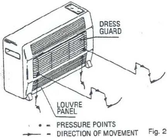
Using both hands, simultaneously apply upward pressure at the bottom left and bottom right of the dress guard, as indicated in FIG 2, and lift up until the wire rods come out of their locations. Ease the bottom of the dress guard forward of the front edge of the reflector and pull down as far as it will go (about 2cms). Pivot the dress guard up until enough space for access is achieved. The dress guard is not removable nor will it open right up. This has been designed like this for safety reasons.
To close the dress guard to its correct position, pivot it back down, lift it up and guide the ends of the wire rods back over their location holes then push down firmly to secure the dress guard in place.
Cleaning the area in front of the tiles must be done with great care as the burner tiles are fragile and are very easily damaged.
Access to the underneath of the heater is gained through the lower louvre panel. This panel is hinged at the bottom and is opened by gripping the top louvre blade about 3cms in from each end, pushing down and pulling out (see FIG 2).
This area needs particular attention and should be gently vacuumed out from time to time. The frequency depends greatly on the environment that the heater is used in, the more furnishings and carpets that are in close proximity to it, the more frequent the cleaning. A check should be made once every month and when dust and fluff become apparent, it should be gently vacuumed out. The fan blades may be rotated by hand whilst vacuuming to ensure all fluff etc, is removed.
DRESS GUARD
The guard is fitted to this appliance to reduce the risk of fire or injury from burns and no part of it should be permanently removed.
FOR PROTECTION OF CHILDREN OR THE INFIRM, A SECONDARY GUARD IS REQUIRED.
FAULT FINDING
| SYMPTOM | POSSIBLE CAUSE | REMEDY |
| Spark failure | (1) Faulty igniter(2) Incorrect spark gap(3) Loose or faulty connections | ReplaceReset to 4.5mmCheck with meter |
| Failure to ignite even with spark present | (1) No gas(2) Incorrect injectors(3) Incorrect gas type(4) Air in gas lines(5) Faulty thermocouple(6) Faulty tilt switch | Check supplyReplace injectorsCheck gas for which unit was intendedPurge all linesReplace ODSReplace |
| Dull or uneven burners | (1) Partially blocked injectors(2) Burner venturi blocked(3) Dirty burner tiles | Clean or replace injectorsCheck and clean (possibly insect such as wasp)Clean with compressed air |
| Burner flashing back | (1) Cracked burner tile(2) Faulty or incorrect injector(3) Injector loose | ReplaceReplace injectorTighten |
| Very high pilot flame | (1) Pilot ports partially blocked | Clean with compressed air or a vacuum cleaner |
Please Note:
Darkening of the heater tile face is a natural consequence of the gas combustion process.
SERVICING
Servicing shall be carried out only by authorised personnel.
If unit fails to ignite after following these instructions, contact your nearest authorised EVERDURE service agent or:
Everdure
101-103 Sheffield Road, Welshpool, Western Australia
TELEPHONE: 1300 766 066
OFFICE HOURS BETWEEN 8am - 4:30pm WST (Perth)
RETAIN THIS DOCUMENT TOGETHER WITH YOUR PURCHASE DOCUMENTS TO ENSURE WARRANTY COVER

everdure
36 MONTHS WARRANTY
- Warranty on Everdure Gas Room Heaters covers constructional defects, faulty materials and/or faulty workmanship for a period of 36 months from the date of purchase.
Replacement or repairs made under warranty are made free of charge provided, if necessary, the heater is delivered to our service department or authorised service agent and freight both ways are paid by the owner. No liability will be accepted for loss or damage in transit. - The purchaser MUST produce proof of date of purchase together with this warranty certificate when making a claim.
- All installation work must be carried out by a qualified tradesperson, must conform to the standard as laid down by the local governing authority and must follow the manufacturers installation instructions.
- Damage or expense incurred as a result of incorrect or unauthorised installation, accident, interference by unauthorised persons or misuse, is NOT covered by this warranty.
- Any claim under this warranty must be made direct to Shriro Australia Pty Limited - Everdure Division, or their authorised agent.
- This warranty does not exclude any condition or warranty implied by the Trade Protection Act 1974 or relevant state laws.
- Damage and malfunction caused to the unit due to excessive linting, will not be covered under this warranty.
FOR FUTURE REFERENCE PLEASE DOCUMENT THE FOLLOWING DETAILS AS SOON AS POSSIBLE AFTER PURCHASE
PURCHASED FROM:
NAME: ....
ADDRESS:
DATE OF PURCHASE: ....
SERIAL NUMBER:
MODEL:
GAS TYPE: ....
IMPORTANT PLEASE READ THESE INSTRUCTIONS CAREFULLY BEFORE USING YOUR NEW EVERDURE HEATER
SHRIRO AUSTRALIA PTY. LIMITED
EVERDURE DIVISION
101 SHEFFIELD ROAD, WELSHPOOL, WESTERN AUSTRALIA
TELEPHONE: 1300 766 066
OFFICE HOURS BETWEEN 8am - 4:30pm WST (Perth)
- EVERDURE
- EVERDURE MODELS 3725, 3621, 3518, 2415
- GENERAL REQUIREMENTS
- NOTE
- MODEL BRIGADIER 3725
- DATA LABEL
- OPERATING INSTRUCTIONS
- GAS SUPPLY
- TO CONNECT
- TO DISCONNECT
- ELECTRICAL SUPPLY
- POWER FAILURE
- MANUAL IGNITION
- ABNORMAL OPERATION
- CONTROLS
- FAN AND FAN SWITCH
- LIGHTING INSTRUCTIONS
- WARNING
- CLEANING
- DRESS GUARD
- SERVICING
- RETAIN THIS DOCUMENT TOGETHER WITH YOUR PURCHASE DOCUMENTS TO ENSURE WARRANTY COVER
- 36 MONTHS WARRANTY
- FOR FUTURE REFERENCE PLEASE DOCUMENT THE FOLLOWING DETAILS AS SOON AS POSSIBLE AFTER PURCHASE
- IMPORTANT PLEASE READ THESE INSTRUCTIONS CAREFULLY BEFORE USING YOUR NEW EVERDURE HEATER
Brand : Omega Altise
Model : Brigadier OABRFNGSS
Category : Heating