OAGCH25 - Heating Omega Altise - Free user manual and instructions
Find the device manual for free OAGCH25 Omega Altise in PDF.


| Product Type | Fan Heater |
| Model | OAGCH25 |
| Brand | Omega Altise |
| Heating Power | 2000W (High) / 1000W (Low) |
| Power Supply | 220-240V ~ 50Hz |
| Dimensions (W x D x H) | 22 x 15 x 28 cm |
| Weight | 1.5 kg |
| Thermostat | Adjustable Thermostat |
| Oscillation | Yes, 70° wide angle |
| Safety Features | Overheat Protection, Tip-Over Switch |
| Control Type | Mechanical Dial |
| Fan Settings | 2 (High Heat / Low Heat / Fan Only) |
| Noise Level | < 45 dB |
| Cable Length | 1.8 m |
| Material | ABS Plastic, Metal Grille |
| Cleaning | Wipe with damp cloth; do not immerse |
| Spare Parts | Replacement filter available |
| Certifications | CE, RoHS |
| Energy Efficiency | Class A |
| Room Size (Up to) | 25 m² |
| Warranty | 2 Years |
Frequently Asked Questions - OAGCH25 Omega Altise
User questions about OAGCH25 Omega Altise
0 question about this device. Answer the ones you know or ask your own.
Ask a new question about this device
Download the instructions for your Heating in PDF format for free! Find your manual OAGCH25 - Omega Altise and take your electronic device back in hand. On this page are published all the documents necessary for the use of your device. OAGCH25 by Omega Altise.
USER MANUAL OAGCH25 Omega Altise
OPERATION, MAINTENANCE AND SAFETY INSTRUCTIONS
Model - OAGCH15 and OAGCH25
Gas Convection Room Heater


omega altise
IMPORTANT SAFETY INSTRUCTIONS
The OMEGA ALTISE gas space heaters are an automatically operated, portable convection heater for use with Natural gas or Universal LPG.
The heater is supplied with an approved flexible hose.
Note: A label is attached to the rear of the heater stating the type of gas for which it has been manufactured and adjusted.
The heater shall be installed in accordance with the manufacturer's instructions, local gas fitting regulations, uniform building regulations, municipal building codes, AS/NZS 5601 installation code for gas burning appliances and equipment and any other relevant statutory regulations.
The heater is intended to be installed as a free standing portable unit, its portability being restricted by the number of gas outlet points being provided.
DO NOT INSTALL IN A FIREPLACE
Special room ventilation may apply in your particular state. If in doubt, contact your local gas authority. Locations where strong drafts occur should be avoided as they may cause unsatisfactory operation of the heater.
The heater should be installed at least 1 meter away from flammable materials, e.g. curtains, and to be 150mm clear of sidewalls.
This appliance is not intended for use by persons (including children) with reduced physical, sensory or mental capabilities, or lack of experience and knowledge, unless they have been given supervision or instruction concerning use of the appliance by a person responsible for their safety.
Children should be supervised to ensure that they do not play with the appliance.
SERVICING SHALL ONLY BE CARRIED OUT BY AUTHORIZED PERSONS
If the supply cord is damaged, DO NOT use the appliance, it must be replaced by the manufacturer, its service agent or similarly qualified persons in order to avoid a hazard.
NOT TO BE CONNECTED TO A L.P.G GAS CYLINDER LOCATED INDOORS
ELECTRICAL AND GAS CONNECTION MUST BE MADE AS PER LOCAL WIRING AND GAS INSTALLATION REGULATIONS.
DO NOT DISCONNECT THE APPLIANCE WITH WET HANDS OR BARE FEET
DO NOT DISCONNECT THE POWER CORD WITH EXTREME FORCE
TO BE INSTALLED BY AN AUTHORIZED PERSON IF CONNECTING TO FIXED CONSUMER PIPING WHERE THIS APPLIANCE IS BEING CONNECTED TO AN EXISTING GAS SUPPLY OUTLET FOR THE FIRST TIME, IT IS RECOMMENDED THE CONNECTION IS MADE BY A LICENSED/AUTHORISED PERSON AND THE SUPPLY PRESSURE IS VERIFIED FOR THE GAS TYPE.
DO NOT place articles on or against this appliance.
DO NOT use or store inflammable materials near this appliance.
DO NOT spray aerosols in the vicinity of this appliance while it is in operation.
DO NOT use this appliance in a marine environment.
DO NOT modify this appliance.
DO NOT use this appliance outdoors.
DO NOT sit on the heater.
DO NOT put articles such as paper into the louvers of the heater
DO NOT cover the heater or place articles like clothes or blanket on the heater.
DO NOT place articles in front of the louvers, or it can cause damage or a fire.
IMPORTANT SAFETY INSTRUCTIONS

DO NOT OPERATE THIS APPLIANCE BEFORE READING THE INSTRUCTION BOOKLET DO NOT PLACE ARTICLES ON OR AGAINST THIS APPLIANCE DO NOT STORE CHEMICALS OR FLAMMABLE MATERIALS OR SPRAY AEROSOLS NEAR THIS APPLIANCE DO NOT OPERATE WITH PANELS, COVERS OR GUARDS REMOVED FROM THIS APPLIANCE DO NOT OPERATE IN A BATHROOM OR BEDROOM DO NOT OPERATE IN AN UNVENTILATED ROOM DO NOT OPERATE IN A ROOM WITH A VOLUME LESS THAN THAT SHOWN IN THE TABLE BELOW DO NOT CONNECT TO AN U.L.P GAS CYLINDER LOCATED IN DOORS
| MINIMUM ROOM SIZE PER MODEL | |
| MODEL | ROOM VOLUME (NG or ULPG) |
| OAGCH25 (25MJ/h) | 62.5m3 |
| OAGCH15(15MJ/h) | 37.5m3 |
DO NOT spray aerosols near this heater while it is in use. Most aerosols contain butane gas which can be a fire hazard if used near this heater when it is in operation.
DO NOT get the remote controller wet or expose it to direct sunlight. DO NOT place containers of liquid on the appliance. Water spillage can cause extensive damage to the appliance and create an electrocution hazard.
DO NOT unplug the heater while it is in operation or while the fans are still cycling, or it may damage the appliance.
DO NOT unplug the power when turn off the heater after use. The fan will keep cycling for 3 minutes until stop.
DO NOT move the heater while it is in operation or while the fans are still cycling.
When the heater is operated for the first time or after long periods of non use a slight odour may be emitted, this is normal. However if the odours persist after switching off the appliance, please contact the service center.
NOTE:
This appliance has been fully function tested prior to packaging.
No adjustment is required or available to the user.
No installation is required apart from connection to gas and electrical supplies. (Fig. 1)
omega altise
GENERAL HEATER LAYOUT
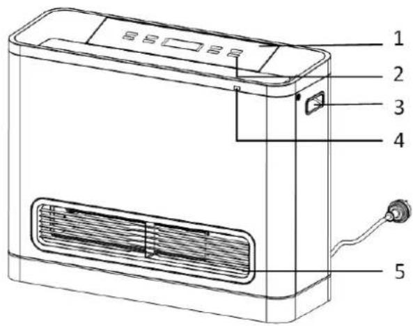
- Control Panel
- ON/OFF Button
- Handle
- Remote control IR Receiver
- Warm Air Outlet
- Remote control IR Receiver

- Gas Inlet Connector
- Temperature Sensor
- Power Cord
- Air Filter
- Power Cord Storage
CONTROL PANEL FUNCTIONS
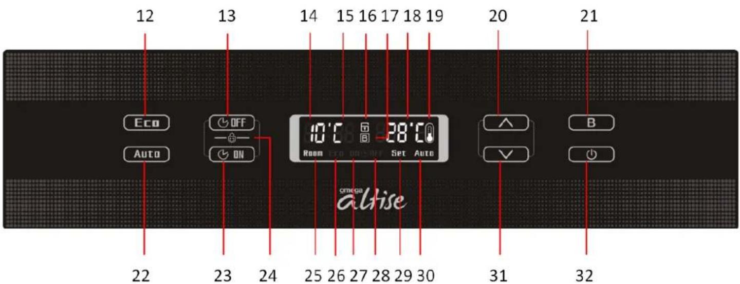
- Economy Button
- Off Timer Set Button
- Current Room Temperature/Hour Display
- Minute Digit Display
- Child Lock Icon
- Boost Mode Display
- Set Temperature Display
-
Combustion Condition Display
-
Increase Button
-
Boost Mode Button
-
Auto Mode Button
-
On Timer Setting Button
- Child Lock Function
- Room Temperature Icon
- ECO Display icon
- ON Timer Icon
- OFF Timer Icon
- Set Temperature Icon
- AUTO Mode Icon
- Decrease Button
- ON/OFF Button
omega altise
REMOTE CONTROL FUNCTIONS

- LCD Display
- ON/OFF Button
- Increase/Decrease
- Operating Mode
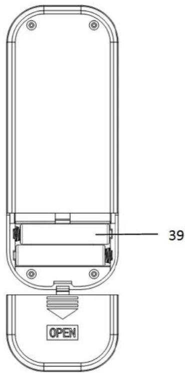
- Timer Function ON/OFF
- Child Lock
- Battery Compartment
GAS SUPPLY DATA
Refer to the rating label attached to the rear of each appliance, the gas supply data as well as the gas type for which the heater has been tested and adjusted for is shown.
OAGCH15
| Gas Type NG ULPG | ||
| Nom. Gas Consumption (MJ/h) 15 15 | ||
| Test Point Pressure (kPa) Boost Mode 0.97 | 1.38 | |
| Main Burner Injector (mm) 1.72 1.2 | ||
| ODS Injector (mm) | 0.3 0.2 |
OAGCH25
| Gas Type NG ULPG | ||
| Nom. Gas Consumption (MJ/h) 25 25 | ||
| Test Point Pressure (kPa) Boost Mode 0.97 | .05 | |
| Main Burner Injector (mm) 2.2 1.66 | ||
| ODS Injector (mm) | 0.3 0.19 |
The OAGCH15 is recommended to heat a room area of 52m2 and the OAGCH25 up to 90m2 .
omega altise
INSTALLATION INSTRUCTIONS
GAS SUPPLY
Your heater is fitted with a flexible hose and bayonet coupling which enables you to connect or disconnect it from the gas supply.
ONLY USE THE HEATER WITH THE CORRECT GAS TYPE IT WAS DESIGNED AND ADJUSTED TO. IF IN DOUBT, CHECK WITH YOUR LOCAL GAS SUPPLIER.
CONNECTING TO GAS SUPPLY
The bayonet plug on the factory fitted flexible hose simply plugs into your home bayonet fitting by pushing and rotating 1/4 turn clockwise.
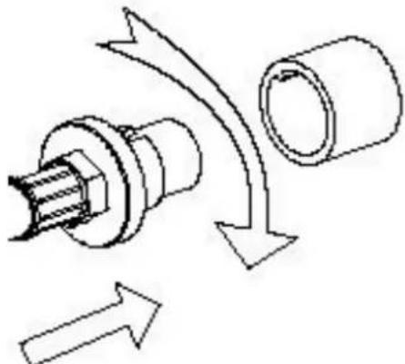
TO DISCONNECT
Apply firm forward pressure to the knurled area, rotate anti clockwise and pull towards you. The hose should now come away from the wall bayonet fitting. Gas is automatically isolated when the hose is disconnected.
ELECTRICAL SUPPLY
Your heater is fitted with a power supply lead, which should be connected to a standard earthed domestic socket outlet.
ABNORMAL OPERATION
As the heater heats up or cools down, expansion or contraction takes place and the occasional 'click' may be heard. This is normal, however, continuous metallic noises, grinding sounds, the smell of gas or any of the symptoms listed on the fault finding chart should be investigated immediately. Turn the appliance off and disconnect the gas and electrical supplies. If the fault cannot be fixed or any doubts exist, contact your nearest OMEGA ALTISE service agent or contact OMEGA ALTISE on the telephone number on the rear page of this booklet.
NOTE:
When using the appliance for the first time or after long periods of disuse or storage, ignition may not occur the first time it is operated as there may be air within the gas supply line. If ignition does not occur after approximately 12 seconds the unit will cease operation automatically and may show an error code E2 or E12. If this occurs press the ON/OFF button twice to restart. For models that are equipped with a remote control, press the OFF button and then press the ON button to restart.
If the error continues to occur after 2-3 attempts, consult the troubleshooting guide on page 11
OPERATING INSTRUCTIONS
TURNING ON THE HEATER
After the gas and power have been connected and the heater turns to standby mode, press the ON/OFF button to turn on the heater.
Press the ON/OFF button again to turn off the heater after use. The fan may keep cycling for 3 minutes until cooled down. DO NOT move nor unplug the heater while the fan is still cycling.
DEFAULT OPERATION
When turning on heater, the initial default operation mode is "AUTO", and default set temperature is 20°C.
The display ON/Combustion indicator icon and "AUTO" mode indicator icon light up.
SET TEMPERATURE ADJUSTMENT
The set temperature may be raised or lowered by use of the INCREASE and DECREASE buttons. For models that are equipped with a remote control the increase and decrease buttons may also be used.
Temperature setting adjusts between 16°C to 30°C in 1°C steps.
AUTO MODE
The default working mode is Auto mode, or you may press the "Auto" button to turn on the Auto mode after turning on the heater. Under this mode, the heater outputs its maximum power then it turns to Economic mode automatically, when the set temperature is reached.
BOOST MODE
When the heater is turned on, press the Boost Mode button to turn on boost heating mode, the display boost mode icon will light up. Under this mode, the heater outputs maximum power. The combustion process will cut off when the room temperature reaches the set temperature, and will re-start with maximum output when the room temperature is 2° C less than set temperature.
ECO MODE
While the heater is on, press the "Eco" button to turn on the Economic Mode. Under this mode, the heater operates with a reduced output power. The combustion process will cut off when the room temperature reaches the set temperature, and will re-start with reduced output when the room temperature is 3°C less than set temperature.
CHILD LOCK
While the heater is on, press the "ON Timer" and "OFF Timer" buttons together for more than 3 seconds to activate the child lock. Once the lock function is on, the child-lock indicator icon lights up on display. Except for the ON/OFF button, all other buttons are invalid. Press the ON/OFF button under lock function, the heater turns off and display shows "--:00 --", and all the buttons become invalid.
To deactivate the child-lock, press the "ON Timer" and "OFF Timer" buttons together for more than 3 seconds again, then the child-lock display indicator icon extinguishes and the lock function is off. All the buttons will return to normal operation.
OPERATING INSTRUCTIONS
ON TIMER FUNCTION
With the heater in standby mode, press the ON Timer button , the ON Timer indicator icon lights ON up, and timer indicator shows "00:00", and the hour clock indicator will flash. Press ∧ or ∨ buttons to set the hour portion of the clock. Each press of the "UP" or "DOWN" button will increase/decrease by 1 hour. The hour clock setting range is 0-23 hours. Then press the "ON Timer" button again to confirm the hour setting and the minute timer portion will start to flash setting. Each press of "UP" or "DOWN" button will increase/decrease by 5 minutes. The minute clock setting range is 0-55. Then press the ON Timer button again or wait for more than 10 seconds, the ON Timer is set and will remain in the memory. Timer indicator stops flashing and begins to count down. The heater turns on automatically when the timer reaches "00:00".
To cancel the ON timer function, press and hold the ON Timer button for 5 seconds and this will cancel the timer setting and erase the memory, display clock indicator will return to "00:00".
OFF TIMER FUNCTION
While the heater is on, press the OFF Timer button , the OFF Timer indicator icon lights up, and OFF timer indicator shows "00:00", the hour clock indicator will flash. Press or buttons to set the
hour portion of the clock. Each press of "UP" or "DOWN" button will increase/decrease by 1 hour. The hour clock setting range is 0-23. Then press the "OFF Timer" button again to confirm the hour setting and the minute portion of the timer will start to flash. Each press of "UP" or "DOWN" button will increase/decrease by 5 minutes. The minute clock setting range is 0-55. Then press the OFF Timer button again or wait for more than 10 seconds, the OFF Timer is set and will remain in the memory. Timer indicator stops flashing and begins to count down. The heater will turn off automatically when the timer reaches "00:00".
To cancel the OFF timer function, press and hold the OFF Timer button for 5 seconds and this will cancel the timer setting and erase the memory, display clock indicator will return to "00:00".
omega altise
MAINTENANCE
The heater needs maintenance, and the following information will help you to keep it looking good and working efficiently.
It is recommended that this appliance be inspected and serviced every year.
Particular attention should be placed on inspection and cleaning of the rear air filter. This should be checked at least once a month.
Always unplug the heater before cleaning.
All parts of the heater can be cleaned by using a soft, damp cloth. DO NOT use solvents to clean any parts.
REMOVING AND CLEANING THE FILTER
Filters require cleaning at least once a week during the heating season to prevent blockages.
Remove the screws (store the screws in a safe place) Lift up the filters carefully to remove it from locating tabs. Remove any dust or lint from the filters with a vacuum cleaner. Put the filters back into position and fix it with screws.

If the power supply cord or any other components of the heater are damaged, they must be replaced by the manufacturer or a suitably qualified person.
Any service or repair work should only be carried out by an authorized person. Service calls for general cleaning, maintenance and wear and tear are not necessarily covered under the warranty. Service calls of this nature may be chargeable.
Faults caused by insufficient gas supply, gas quality, installation errors or operation errors are not covered by the warranty
TROUBLE SHOOTING
Use the following chart to help determine whether a service call is required. However if you are unsure about the way your heater is operating, contact OMEGA ALTISE or your local service agent.
| Cause\Fault | No Display | Ignition Failure | Flame Failure | Gas Smell | Long time to heat the room | Remote controller not working | Weak air flow | Possible Remedy |
| Not plugged in or turned off | ● | Plug in power cord and turn power on | ||||||
| Main power failure | ● | ● | Re-ignition when power is on | |||||
| Gas failure | ● | ● | Turn on gas | |||||
| Air in hose | ● | Repeat ignition | ||||||
| Room too large | ● | Check page 5 | ||||||
| Louvre blocked | ● | ● | ● | Remove obstruction | ||||
| Dust on filter | ● | ● | ● | Clean the filter | ||||
| Air filter blocked | ● | ● | ● | Remove obstruction | ||||
| Gas leakage | ● | ● | Isolate gas supply, call service | |||||
| Child Lock set | ● | Cancel lock function | ||||||
| Flat battery | ● | Replace batteries | ||||||
| Wrong gas type | ● | ● | Check and use the correct gas type |
ERROR CODES
Refer to the table below for probable cause and the suggested remedy
| Code | Possible Cause | Suggested Remedy |
| E01【Flame detection circuit faulty】 | Appliance detects flame before ignition or turn off | Shut off the gas |
| E02【Flame failure】 | Ignition failure or flame failure | Check the gas supply, gas type, lock function. Turn on and off the heater again. If the heater fails to ignite after 5 times turn, call the service. |
| E03【Tilt switch fault】 | Appliance tilted more than 45° | Ensure appliance is level & upright. Service call if repeated. |
| E04【Anti-burn protection】 | Over heat or anti burning fuse damage | Call service |
| E05【Room temperature sensor faulty】 | Sensor damage or disconnection | Call service |
| E06【Motor fan faulty】 | Fan damage or disconnection | Call service |
| E07【Solenoids faulty】 | Solenoids damage or disconnection | Call service |
| E08【Proportional valve faulty】 | Proportional valve damage or disconnection | Call service |
| E09【Relay Faulty】 | Relay damage | Call service |
| E11【Temperature sensor faulty】 | Sensor damage or disconnection | Call service |
| E13【Over heat protection】 | Combustion chamber temperature more than 100°C | Clean the air filter and Louvre |
| E12【Thermocouple faulty】 | Thermocouple damage or oxygen shortage | Clean filters, Ventilate room. Call service if repeated |
| E20【Gas valve leakage】 | Appliance detects flame before solenoids open | Call service |
omega altise
SPECIFICATIONS
GENERAL SPECIFICATION
| Power Supply: | 110-240V a.c. 50/60Hz 34W Max. |
| Gas Control: | Proportional valve |
| Convection Fan: | DC Variable speed fan |
| Burner: | Ceramic Infrared |
| Ignition System: | Electronic pulse ignition |
| Remote Control: | Infrared - Battery supply 2x AAA size |
| Operation: | ntegrated touch control/remote control |
| Gas Supply Hose: | 3/8" BSP Bayonet quick connect |
| Safety Devices: | Over heat, Anti-burn, Flame Failure, Oxygen depletion Sensor, Tilt-over switch. |
WEIGHTS AND MEASURES
| Model Packaging Size(mm) | Appliance Dimensions (mm) Weight (kg) | |||||
| A B C D | ||||||
| OAGCH15 | 530x262x550 | 480 | 485 | 190 | 170 | 11.3 |
| OAGCH25 | 660x282x550 | 610 | 485 | 210 | 235 | 13.2 |

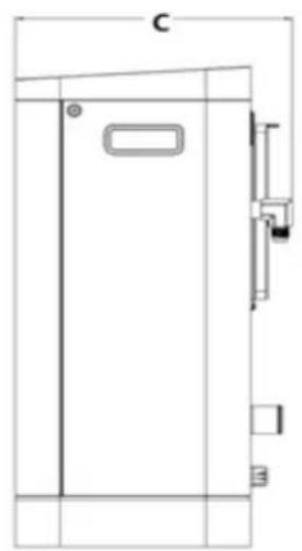
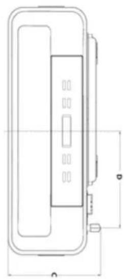
omega altise
EXPLODED VIEW
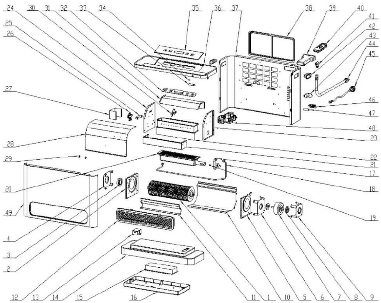
| No. | Description | QTY | No. | Description | QTY |
| 1 | Fan blade assembly | 1 | 26 | ODS (Oxygen depletion sensor) | 1 |
| 2 | Air duct left bracket | 1 | 27 | ODS wind shield | 1 |
| 3 | Axle anti vibration ring | 1 | 28 | Combustion chamber heat shield | 1 |
| 4 | Axle fixing bracket | 1 | 29 | Fuse fixing bracket | 2 |
| 5 | Air duct right bracket | 1 | 30 | Ignition pin | 1 |
| 6 | Motor inner fixing bracket | 1 | 31 | Combustion chamber guide plate | 1 |
| 7 | Fan motor | 1 | 32 | Display | 1 |
| 8 | Motor anti vibration ring | 2 | 33 | Remote receiver | 1 |
| 9 | Motor outer fixing bracket | 1 | 34 | Infrared filter plate | 1 |
| 10 | Air duct back panel | 1 | 35 | Control panel glass | 1 |
| 11 | Air duct front panel | 1 | 36 | Top cover | 1 |
| 12 | Vent louver assembly | 1 | 37 | Back panel | 1 |
| 13 | Igniter | 1 | 38 | Air filter assembly | 1 |
| 14 | Base | 1 | 39 | Remote controller capsule | 1 |
| 15 | Main PCB | 1 | 40 | Remote controller | 1 |
| 16 | Base cover | 1 | 41 | Brass connector | 1 |
| 17 | Main gas pipe assembly | 1 | 42 | Handle slot | 2 |
| 18 | ODS gas pipe | 1 | 43 | Wire rack | 2 |
| 19 | Nozzle | 1 | 44 | Hose assembly | 1 |
| 20 | Burner assembly | 1 | 45 | Power cord | 1 |
| 21 | Combustion Chamber Cover | 1 | 46 | Room temperature sensor cover | 1 |
| 22 | Combustion Chamber assembly | 1 | 47 | Room temperature sensor base | 1 |
| 23 | Combustion Chamber right bracket | 1 | 48 | Proportional valve assembly | 1 |
| 24 | Combustion Chamber left bracket | 1 | 49 | Front panel | 1 |
| 25 | ODS fixing bracket | 1 |
omega altise
SERVICING
Servicing shall only be carried out by an authorised person. OMEGA ALTISE recommends that this room heater be serviced every 24 months to ensure the heater continues to operate in a safe and optimum condition.
This is part of general maintenance and any costs incurred are not covered by warranty. If the unit fails to ignite after following these instructions, contact your authorised OMEGA ALTISE service centre.
NOTES/SERVICE RECORD
omega altise
WIRING DIAGRAM

A division of Shriro Australia Pty Ltd 104 Vanessa St Kingsgrove NSW 2208 In Australia: 1300 795 572 In New Zealand: (09) 415 6000 www.omegaaltise.com
IM Rev: 1.3
omega altise

- OPERATION, MAINTENANCE AND SAFETY INSTRUCTIONS
- OMEGA ALTISE
- IMPORTANT SAFETY INSTRUCTIONS
- DO NOT INSTALL IN A FIREPLACE
- SERVICING SHALL ONLY BE CARRIED OUT BY AUTHORIZED PERSONS
- NOTE
- GENERAL HEATER LAYOUT
- CONTROL PANEL FUNCTIONS
- REMOTE CONTROL FUNCTIONS
- GAS SUPPLY DATA
- INSTALLATION INSTRUCTIONS
- GAS SUPPLY
- CONNECTING TO GAS SUPPLY
- TO DISCONNECT
- ELECTRICAL SUPPLY
- ABNORMAL OPERATION
- OPERATING INSTRUCTIONS
- TURNING ON THE HEATER
- DEFAULT OPERATION
- SET TEMPERATURE ADJUSTMENT
- AUTO MODE
- BOOST MODE
- ECO MODE
- CHILD LOCK
- ON TIMER FUNCTION
- OFF TIMER FUNCTION
- MAINTENANCE
- ALWAYS UNPLUG THE HEATER BEFORE CLEANING
- ALL PARTS OF THE HEATER CAN BE CLEANED BY USING A SOFT, DAMP CLOTH. DO NOT USE SOLVENTS TO CLEAN ANY PARTS
- TROUBLE SHOOTING
- ERROR CODES
- SPECIFICATIONS
- EXPLODED VIEW
- SERVICING
Brand : Omega Altise
Model : OAGCH25
Category : Heating