
XTP FT HD 4K - Audiovisual Equipment Extron - Free user manual and instructions
Find the device manual for free XTP FT HD 4K Extron in PDF.


| Product Type | Fiber Optic Transmitter |
| Model | XTP FT HD 4K |
| Brand | Extron |
| Video Support | Up to 4K@60Hz, 4:4:4 |
| Input Interface | HDMI |
| Output Interface | LC fiber optic (single mode or multimode) |
| Maximum Distance | Up to 300 meters (multimode) or 10 km (single mode) |
| Dimensions (H x W x D) | 1.7 x 4.3 x 3.0 inches (4.3 x 10.9 x 7.6 cm) |
| Weight | 1.0 lb (0.45 kg) |
| Power Supply | 12V DC, 1.0 A (included) |
| Power Consumption | 8 watts (max) |
| HDCP Compliance | HDCP 2.2 |
| EDID Management | Extron EDID Minder |
| Key Features | Signal extension, cable equalization, skew delay |
| Enclosure Type | Metal, half-rack width |
| Mounting | Desk, rack, or wall mountable |
| Operating Temperature | 32°F to 122°F (0°C to 50°C) |
| Regulatory Compliance | CE, FCC Class A, RoHS |
| Included Accessories | Power supply, mounting kit, user manual |
| Warranty | 3 years parts and labor |
Frequently Asked Questions - XTP FT HD 4K Extron
User questions about XTP FT HD 4K Extron
0 question about this device. Answer the ones you know or ask your own.
Ask a new question about this device
Download the instructions for your Audiovisual Equipment in PDF format for free! Find your manual XTP FT HD 4K - Extron and take your electronic device back in hand. On this page are published all the documents necessary for the use of your device. XTP FT HD 4K by Extron.
USER MANUAL XTP FT HD 4K Extron
Safety Instructions • English

WARNING: This symbol, when used on the product, is intended to alert the user of the presence of uninsulated dangerous voltage within the product's enclosure that may present a risk of electric shock.
ATTENTION: This symbol, ⚠, when used on the product, is intended to alert the user of important operating and maintenance (servicing) instructions in the literature provided with the equipment.
For information on safety guidelines, regulatory compliances, EMI/EMF compatibility, accessibility, and related topics, see the Extron Safety and Regulatory Compliance Guide, part number 68-290-01, on the Extron website, www.extron.com.
© 2015-2019 Extron Electronics. All rights reserved. www.extron.com
Trademarks
All trademarks mentioned in this guide are the properties of their respective owners. The following registered trademarks ( ^® ), registered service marks ( ^SM ), and trademarks ( ^TM ) are the property of RGB Systems, Inc. or Extron Electronics (see the current list of trademarks on the Terms of Use page at www.extron.com):
| Registered Trademarks (®) |
| Extron, Cable Cubby, ControlScript, CrossPoint, DTP, eBUS, EDID Manager, EDID Minder, Flat Field, FlexOS, Global Configurator, Global Scripter, GlobalViewer, Hideaway, HyperLane, IP Intercom, IP Link, Key Minder, LinkLicense, LockIt, MediaLink, MediaPort, NetPA, PlenumVault, PoleVault, PowerCage, PURE3, Quantum, Show Me, SoundField, SpeedMount, SpeedSwitch, System INTEGRATOR, TeamWork, TouchLink, V-Lock, VideoLounge, VN-Matrix, VoiceLift, WallVault, WindoWall, XTP, XTP Systems, and ZipClip |
| Registered Service Mark(SM): S3 Service Support Solutions |
| Trademarks(TM) |
| AAP, AFL (Accu-Rate Frame Lock), ADSP (Advanced Digital Sync Processing), Auto-Image, CableCover, CDRS (Class D Ripple Suppression), Codec Connect, DDSP (Digital Display Sync Processing), DMI (Dynamic Motion Interpolation), Driver Configurator, DSP Configurator, DSVP (Digital Sync Validation Processing), eLink, EQIP, Everlast, FastBite, FOX, FOXBOX, IP Intercom HelpDesk, MAAP, MicroDigital, Opti-Torque, PendantConnect, ProDSP, QS-FPC (QuickSwitch Front Panel Controller), Room Agent, Scope-Trigger, ShareLink, SIS, Simple Instruction Set, Skew-Free, SpeedNav, StudioStation, Triple-Action Switching, True4K, VectorTM 4K , WebShare, XTRA, and ZipCaddy |
FCC Class A Notice
This equipment has been tested and found to comply with the limits for a Class A digital device, pursuant to part 15 of the FCC rules. The Class A limits provide reasonable protection against harmful interference when the equipment is operated in a commercial environment. This equipment generates, uses, and can radiate radio frequency energy and, if not installed and used in accordance with the instruction manual, may cause harmful interference to radio communications. Operation of this equipment in a residential area is likely to cause interference. This interference must be corrected at the expense of the user.
Class 1 Laser Product
Any service to this product must be carried out by Extron Electronics and its qualified service personnel.
CAUTION: Using controls, making adjustments, or performing procedures in a manner other than what is specified herein may result in hazardous radiation exposure.
NOTE: For more information on safety guidelines, regulatory compliances, EMI/EMF compatibility, accessibility, and related topics, see the “Extron Safety and Regulatory Compliance Guide” on the Extron website.
Conventions Used in this Guide
Notifications
The following notifications are used in this guide:

WARNING: Potential risk of severe injury or death.
CAUTION: Risk of minor personal injury.
NOTE: A note draws attention to important information.
TIP: A tip provides a suggestion to make working with the application easier.
Software Commands
Commands are written in the fonts shown here:
^AR Merge Scene, ,∅p1 scene 1,1 ^B 51 ^W^C.∅ [∅1] R∅004∅03∅0∅04∅0∅08∅0∅06∅0 [∅2] 35 [17] [∅3]
Esc X1 * X17 * X20 * X23 * X21 CE ←
NOTE: For commands and examples of computer or device responses used in this guide, the character "∅" is used for the number zero and "O" is the capital letter "O."
Computer responses and directory paths that do not have variables are written in the font shown here:
Reply from 208.132.180.48: bytes=32 times=2ms TTL=32 C:\Program Files\Extron
Variables are written in slanted form as shown here:
ping xxx.xxx.xxx.xxx -t SOH R Data STX Command ETB ETX
Selectable items, such as menu names, menu options, buttons, tabs, and field names are written in the font shown here:
From the File menu, select New. Click the OK button.
Specifications Availability
Product specifications are available on the Extron website, www.extron.com.
Extron Glossary of Terms
A glossary of terms is available at http://www.extron.com/technology/glossary.aspx.
Contents
Introduction.... 1
Guide Overview ...... 1
Product Descriptions .... 1
System Compatibility 2
Cable Transmission....2
Control Methods....3
Features 3
XTP Interconnection Features 3
Video Features....3
Audio Features 3
Control Features 4
General Features 4
Installation....5
Rear Panel Connectors....5
Transmitter inputs 5
Transmitter XTP interconnection 6
Transmitter power....6
Connection Details 7
HDMI Connection....7
RS-232 and IR Communication 8
Power Connection 8
Operation....10
Transmitter Front Panel Features 10
HDMI Audio Switch 11
EDID....11
Audio Output Overview....11
Reset Modes....12
SIS Configuration and Control....13
Host Device Connection 13
SIS Overview 13
Host and Device Communication....13
Error Responses....13
Using the Command and Response Tables for
SIS Commands 14
Symbol Definitions 14
Command and Response Tables....15
Audio Configuration Commands 15
EDID Commands....16
Advanced Configuration Commands ...... 16
Device Commands 17
Configuration Software....18
Software Installation.... 18
Software Download Center Page....18
Software Product Page....19
Software Connection....20
Software Operation.... 21
Menu Bar 21
Transmitter Configuration....24
Reference Information 28
Mounting 28
Tabletop Mounting....28
Furniture Mounting.... 28
Rack Mounting 28
Firmware Download....29
Introduction
This section contains general information about this guide and the Extron XTP FT HD 4K Fiber Optic Transmitter. Topics in this section include:
• Guide Overview
• Product Descriptions
- Features
Guide Overview
This guide contains installation, operation, control, and reference information for the XTP FT HD 4K fiber optic transmitter.
NOTE: See an XTP matrix switcher user guide at www.extron.com for matrix applications.
In this guide, the terms "XTP FT HD 4K" and "transmitter" are used interchangeably to refer to the XTP FT HD 4K fiber optic transmitter.
Product Descriptions
The XTP FT HD 4K sends video, audio, bidirectional RS-232 and IR, and Ethernet signals over a fiber optic cable. It extends digital video signals (up to 4096x2160 @ 24 Hz) with deep color support up to 500 m (1,640 feet) using a multimode OM4 fiber cable or up to 10 km (6.2 mi) with a singlemode fiber cable.
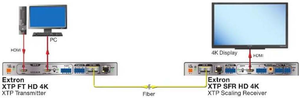
The following diagram shows one way the XTP FT HD 4K can be integrated in an XTP point-to-point application.
flowchart
graph TD
    A["Extron XTP FT HD 4K XTP Transmitter"] -->|HDMI| B["PC"]
    B --> C["Extron XTP SFR HD 4K XTP Scaling Receiver"]
    C -->|Fiber| D["4K Display"]
    D --> E["HDMI"]
Figure 1. Typical Point-to-Point Application
The XTP FT HD 4K is compatible with XTP systems, but the maximum video resolution may be limited with different XTP devices. See the table below for maximum video resolutions and refresh rates for various inputs and outputs.
| Maximum Resolution and Refresh Rates for XTP Systems | |||||
| Output | |||||
| Non-4K 4K | Fiber 4K Twisted | Pair | 4K PLUS | ||
| Input | Analog 1920x1200 | @ 60 Hz | 1920x1200@ 60 Hz | 1920x1200@ 60 Hz | 1920x1200@ 60 Hz |
| Non-4K Digital 2048x1080@ 60 Hz | 2048x1080@ 60 Hz | 2048x1080@ 60 Hz | 2048x1080@ 60 Hz | ||
| 4K Fiber 2048x1080@ 60 Hz | 4096x2160@ 24 Hz | 4096x2160@ 24 Hz | 4096x2160@ 24 Hz | ||
| 4K Twisted Pair 2048x1080@ 60 Hz | 4096x2160@ 24 Hz | 4096x2160@ 30 Hz | 4096x2160@ 30 Hz | ||
| 4K PLUS 2048x1080@ 60 Hz | 4096x2160@ 24 Hz | 4096x2160@ 30 Hz | 4096x2160@ 60 Hz | ||
Cable Transmission
The device is further categorized by the type of fiber optic cable, multimode (MM) or singlemode (SM), which defines the effective range of transmission:
- Multimode — Long distance, up to 500 m (1,640 feet) depending on the fiber cable
- Singlemode — Very long distance, up to 10 km (6.21 miles)
NOTES:
- The multimode and singlemode models are physically and functionally identical with the exception of the effective range of transmission.
- Different modes are not compatible with each other.
- A color-coded sticker identifies the type of SFP module: orange for multimode and yellow for singlemode.
Control Methods
To directly control the device, use one of the following methods:
- Simple Instruction Set (SIS) commands (see SIS Configuration and Control on page 13)
• XTP System Configuration Software (see Configuration Software no page 18)
Certain features can also be controlled through an XTP matrix switcher (see the XTP matrix switcher user guide at www.extron.com).
NOTE: If the XTP FT HD 4K is connected to an XTP matrix switcher, configure it through the XTP matrix switcher (se the XTP matrix switcher user guide for SIS command or the XTP System Configuration Help File for software details).
Features
XTP Interconnection Features
- Reliable cable infrastructure — Transmits video, audio, bidirectional RS-232 and IR, and Ethernet over a fiber optic cable.
- Fiber optic cable compatibility — Supports maximum performance over long distances.
- Bidirectional RS-232 and IR insertion for AV control — Allows remote AV devices to be controlled without the need for additional cabling.
- Ethernet extension — Reduces independent network drops required within a system with centralized 10/100 Ethernet communication.
- Signal and link status LED indicators for XTP ports — Provides a means for validating signal flow and operation from transmitter to receiver, allowing quick identification of connectivity issues.
Video Features
- Computer and video resolutions — Supports up to 4K (4096x2160 @ 24 Hz) at 4:4:4 color sampling over one fiber cable.
- HDMI specification features — Include data rates up to 10.2 Gbps, Deep Color up to 12-bit, 3D, and HD lossless audio formats.
- HDCP compliance — Ensures display of content-protected media and interoperability with other HDCP-compliant devices.
- HDMI loop-through with selectable audio control — Features an active HDMI output with support for embedded audio for connection to a local monitor.
Audio Features
- Multiple embedded audio formats — Supports a broad range of multi-channel audio signals, providing reliable operation with HDMI sources.
- Selectable analog stereo audio input embedding — Supports balanced or unbalanced audio for extended transmission by embedding stereo audio into the signal stream. This feature enables direct connection of separate stereo audio signals from a laptop, Blu-ray Disc™ player, or other device.
- Audio input gain and attenuation adjustment — Sets the level of gain or attenuation, eliminating noticeable volume differences when switching between sources.
Control Features
- Front panel USB configuration port — Provides convenient access for setup, configuration, and firmware updates.
- Extron XTP System Configuration Software compatibility — Allows for easy setup and commissioning.
General Features
- XTP compatibility — Provides a flexible signal switching and distribution solution that is completely integrated, ensuring reliable routing of multiple digital and analog formats.
- EDID Minder — Automatically manages EDID communication between connected devices. It ensures that all sources power up properly and reliably outputs content for display.
- Key Minder — Authenticates and maintains continuous HDCP encryption between input and output devices to ensure quick and reliable switching in professional AV environments, while enabling simultaneous distribution of a single source signal to one or more displays.
- HDCP visual confirmation — Provides a green signal when encrypted content is sent to a non-compliant display, providing immediate visual confirmation that protected content cannot be viewed on the display.
- EDID and HDCP transmission support — Actively buffers DDC channels, allowing continuous communication between source and display.
- Internal color bars test pattern — Helps with setup and calibration.
- User-selectable HDCP authorization — Allows individual inputs to appear HDCP compliant or non-HDCP compliant to the connected source, which is beneficial if the source automatically encrypts all content when connected to an HDCP-compliant device. Protected material is not passed in non-HDCP mode.
- LED indicators — Provide visual indication of signal presence, HDCP, selected audio input format, audio signal clipping, and power.
- Lockit HDMI cable lacing brackets — Secure HDMI cables to the HDMI connectors.
- 1" (2.5 cm) high, half rack width metal enclosure — Allows for discreet placement and concealment.
- Highly reliable, energy-efficient external universal power supply included — Provides worldwide power compatibility, with high demonstrated reliability and low power consumption for reduced operating costs.
Installation
This section contains the installation procedures and operation methods for the XTP FT HD 4K. Topics in this section include:
• Rear Panel Connectors
- Connection Details
Rear Panel Connectors

A HDMI input connector
B HDMI loop-through connector
© Analog audio input connector
RS-232 and IR Over XTP connector (see next page)
E XTP output connector (see next page)
F LAN connector (see next page)
G Power connector and LED (see next page)
Figure 2. XTP FT HD 4K Rear Panel Connectors
Transmitter inputs
NOTES:
- For HDMI cables, the maximum cable length is 15 feet (4.6 meters).
- Use Extron LockIt Cable Lacing Brackets to secure HDMI connectors to the device (see HDMI Connection on page 7).
A HDMI input connector — Connect a digital video source device to the HDMI input connector. It accepts HDMI, DVI (with an appropriate adapter), or dual mode DisplayPort video sources.
B HDMI loop-through connector — Connect a digital video display to the HDMI loop-through connector for a local display of the HDMI input (see HDMI Audio Switch on page 11 to select local audio output options). A display that is not HDCP-compliant displays a green screen when HDCP encrypted content is sent to it.
© Analog audio input connector — Connect an audio source to the 5-pole captive screw connectors. Wire the connector as shown in figure 3.
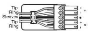
Balanced Audio Input
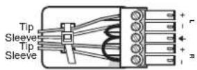
Unbalanced Audio Input
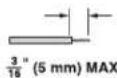
Do not tin the wires!
Figure 3. Audio Input Wiring
Transmitter XTP interconnection
RS-232 Over XTP connector — To pass bidirectional serial or other control signals between XTP-compatible devices, connect a control device to the 5-pole captive screw connector. The connector includes only the two poles labeled "RS-232" and shares the ground pole with the IR poles.
IR Over XTP connector — To transmit and receive IR signals (up to 56 kHz), connect a control device to the 5-pole captive screw connector. This port includes the two poles labeled "IR" and shares the ground pole with the RS-232 poles.
NOTE: RS-232 and IR data can be transmitted simultaneously (see RS-232 and IR Communication on page 8 for wiring details).
E XTP output connector — Connect an XTP fiber receiver or matrix switcher to the XTP fiber output connector.
4 WARNING: Potential risk of severe injury. The XTP FT HD 4K outputs continuous invisible light, which may be harmful to the eyes; use with caution.
NOTE: Ensure the proper fiber optic cable is used. Typically, singlemode fiber optic cable has a yellow jacket and multimode fiber optic cable has an orange or aqua jacket.
F LAN connector — Connect a control device or device to be controlled to the pass-through LAN connector for 10/100Base-T Ethernet communication. LEDs on the connector indicate link and activity status.
Transmitter power
G Power connector and LED — Connect the external 12 V, 1.5 A power supply to the 2-pole captive screw connector. For wiring considerations, see Power Connection on page 8. The Power LED lights to indicate the device is receiving power.
Connection Details
HDMI Connection
To secure the HDMI cable to the HDMI input connector, use an Extron LockIt Cable Lacing Bracket and a tie wrap.
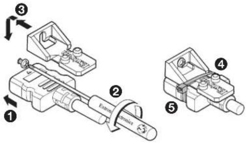
Figure 4. Installing the LockIt Cable Lacing Bracket
- Plug the HDMI cable into the panel connection (see figure 4, ①).
-
Loosen the HDMI connection mounting screw from the panel (②) enough to allow the LockIt to be placed over it. The screw does not have to be removed.
-
Place the LockIt on the screw and against the HDMI connector (③), and then tighten the screw to secure the bracket.
-
Loosely place the included tie wrap around the HDMI connector and the LockIt ( ④).
-
While holding the connector securely against the cable lacing bracket, use pliers or similar tools to tighten the tie wrap, then remove any excess length (⑤).
ATTENTION:
RS-232 and IR Communication
The RS-232 and IR Over XTP connector is for pass-through transmission of serial signals, such as projector control signals, and infrared data. To pass bidirectional serial command signals between XTP-compatible devices, connect a control device to the three poles (Tx, Rx, and G) under "RS-232" of the 5-pole captive screw connector. To transmit and receive IR signals, connect a control device to the three poles (G, Tx, and Rx) under "IR." The ground (G) pole is shared.
NOTE: RS-232 and IR data can be transmitted or received simultaneously (see figure 5 for wiring considerations).
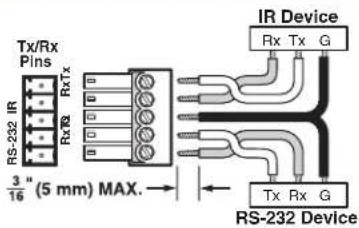
Figure 5. RS-232 and IR Over XTP Connector Wiring Configuration
ATTENTION: The length of the exposed wires in the stripping process is important.
Apply power to the transmitter locally with the provided power supply (if necessary, see figure 6 for wiring considerations).
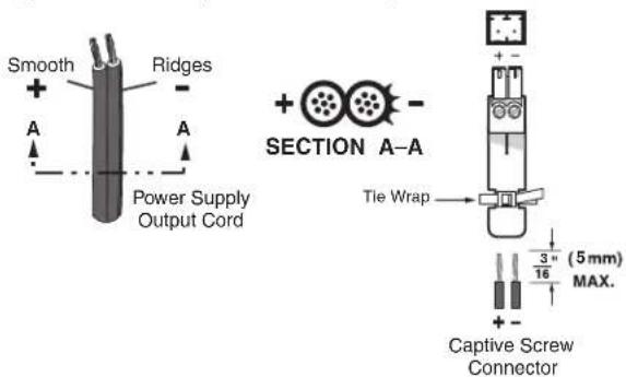
Figure 6. Power Wiring
See the notifications on the next page for other considerations.

WARNING: The wires must be kept separate while the power supply is plugged in. Remove power before wiring.
TIP: Do not tin the stripped power supply leads. Tinned wires are not as secure in the captive screw connectors and could be pulled out.
Operation
After all transmitters and their connected devices are powered up, the system is fully operational. If any problems are encountered, verify that the cables are routed and connected properly. If problems persist, call the Extron S3 Sales & Technical Support Hotline (see the contact numbers on the last page of this guide for the nearest Extron office).
This section contains information about the local operation of the XTP FT HD 4K as well as the operational indicators. Topics in this section include the following:
• HDMI Audio Switch
• EDID
• Audio Output Overview
- Reset Modes
• Transmitter Front Panel Features
Transmitter Front Panel Features

Figure 7. XTP FT HD 4K Front Panel Features
Power LED indicator — Lights when power is applied to the device from the power supply. There are two Power LED indicators, one on the front panel and one on the rear panel (see figure 2, G on page 5).
B Configuration connector — Connect a host device to the female USB mini-B connector to configure the connected transmitter or update firmware.
© Input LED indicators
• Signal — Lights when an active video signal is detected from the source.
- HDMI Audio — Lights when the HDMI audio input is selected.
- HDCP — Lights when the input signal is encrypted.
• Analog Audio — Lights when the analog audio input is selected.
- Audio Signal Clip — Lights when the analog audio input signal remains above -3 dBFS. The LED remains lit for 200 milliseconds after the signal falls below -3 dBFS.
HDMI Audio Switch
The rear panel HDMI audio switches mute or unmute the embedded audio on the related HDMI connector (see figure 2, B on page 5). The audio switch affects the audio on the HDMI loop-thru connector. The LED next to the switch lights when HDMI audio is enabled.
- Hold the HDMI audio switch up until the LED lights (about 1 second) to enable embedded audio on the associated HDMI connector.
- Hold the HDMI audio switch down (until the LED turns off (about 1 second) to disable embedded audio on the associated HDMI connector.
The switch returns to the middle position after it has been released so the device can continue to be controlled through SIS commands.
EDID
The XTP FT HD 4K can record and save EDID in a user memory location on the transmitter. EDID can come from the loop-through display on the transmitter. For EDID management, use the XTP System Configuration Software (see EDID Minder on page 26).
NOTE: In matrix applications, EDID on the transmitter is assigned by the matrix switcher using the XTP System Configuration Software.
Audio Output Overview
By default, the XTP FT HD 4K prioritizes embedded digital audio over analog audio to send over the XTP communication. Use SIS commands (see SIS Configuration and Control on page 13) or the XTP System Configuration Software (see Configuration Software on page 18) to manually select the audio input.
NOTES:
- To pass analog audio without video to a display connected to the HDMI output connector on a connected receiver, the transmitter sends a black video signal to simulate one of the following video signals:
- 720p @ 50 Hz
- 720p @ 60 Hz (default)
• 1080p @ 60 Hz - To set the black video signal, see the Black video signal SIS commands on page 15 or Transmitter device settings on page 24.
Reset Modes
Use the recessed Reset button (see figure 8, Ⓐ) on the rear panel of the transmitter to return the device to default settings or to restore factory-shipped firmware.

Figure 8. Reset Button
| Rest Mode Summary | |||
| Mode Activation Result | Purpose/Notes | ||
| Factory Firmware Reset (mode 1) | Press and hold the recessedResetbutton while applying power to the device. | The device reverts to the factory default firmware for a single power cycle. | Use this reset to return the firmware to the factory version temporarily if an incompatibility issue arises with the current firmware. |
| NOTE: After this reset, update the device with the latest firmware version. Do not operate the device with the firmware version that results from this mode reset. | NOTE: If this reset was performed by mistake or is no longer desired, cycle power to the device again to restore the firmware version running prior to the reset. | ||
| User Settings Reset (mode 5) | Hold down theResetbutton until the Power LED blinks three times (over approximately 9 seconds). Then, press theResetbutton again momentarily (<1 second). | The device reverts user settings to the factory default values (firmware excluded).All user configurations reset to default values including real-time adjustments.The front panel Power LED blinks four times in quick succession during the reset. | Use this reset to restart with the default configuration. This is equivalent to the ZXXX SIS command (see theReset modeSIS command on page 17). |
SIS Configuration and Control
This section contains SIS communication details and SIS commands and responses when the host device is connected directly to an XTP FT HD 4K. Topics in this section include the following:
- Host Device Connection
• SIS Overview
• Command and Response Table
Host Device Connection
Use a connected computer running the Extron DataViewer utility to send and receive SIS commands and responses. To connect directly to an XTP FT HD 4K, connect the computer to the front panel USB configuration connector (see figure 7, B on page 10).
SIS Overview
Host and Device Communication
SIS commands consist of one or more characters per field. No special characters are required to begin or end a command sequence. When the XTP FT HD 4K determines that a command is valid, it executes the command and sends a response to the host device. All responses from the transmitter to the host device end with a carriage return and a line feed (CR/LF = ←), which signals the end of the response character string. A string is one or more characters.
Error Responses
If the transmitter determines a command is invalid or contains invalid parameters, it returns an error response to the host. The following error codes may apply to either device:
$$ E 0 1 = \text { Invalid input number } \quad E 1 4 = \text { Not valid for this configuration } $$
$$ E 1 \emptyset = \text { Invalid command } E 1 7 = \text { Invalid command for signal type } $$
$$ E 1 2 = \text { Invalid port number } E 2 2 = \text { Busy } $$
$$ E 1 3 = \text { Invalid parameter } $$
Using the Command and Response Tables for SIS Commands
The command and response tables for SIS commands list the commands that the transmitter recognizes as valid, the responses returned to the host, a description of the command function or results of executing the command, and some examples of commands in ASCII.
NOTE: Uppercase and lowercase text are interchangeable unless otherwise stated.
Symbol Definitions
The table below shows the hexadecimal equivalent of ASCII characters used in the command and response tables. Hexadecimal values contain two digits. The following symbols are commonly used throughout the command and response tables.
| ASCII and Hexadecimal Conversion Table | ||||||||||||||||||
| Second Hexadecimal Digit | ||||||||||||||||||
| 0 1 | 2 3 | 4 5 | 6 | 7 8 | 9 | A B | C D | E F | ||||||||||
| First Hexadecimal Digit | 0 | LF | ← | |||||||||||||||
| 1 | Esc | |||||||||||||||||
| 2 | ● | ! | “ | # | $ | % & | ‘ | ( ) * | + , | - . | / | |||||||
| 3 | ∅ 1 | 2 3 | 4 5 | 6 | 7 | 8 | 9 | : ; | < = | > ? | ||||||||
| 4 | @ A | B C | D E | F G | H I | J K | L M | N O | ||||||||||
| 5 | P Q | R S | T U | V W | X Y | Z [ | \ ] | ^ _ | ||||||||||
| 6 | ` a b c d e f g h i j k l m n o | |||||||||||||||||
| 7 | p q r s t u v w z y z { | } ~ | |||||||||||||||||
← = Carriage return and line feed (LF)
← = Carriage return with no line feed
| = Pipe (can be used interchangeably with the ← character).
- = Space
Esc = Escape key
W = Can be used interchangeably with the Esc character.
Command and Response Tables
The following commands are for direct connection to the XTP FT HD 4K (see the XTP matrix switcher user guide for commands sent from the matrix switcher to the transmitter).
| Command ASCII Command (Host to Device) | ASCII Response (Device to Host) | Additional Description | |
| Audio Configuration Commands | |||
| Input audio format selection | |||
| Set input audio format | EscI X1 AFMT←Afmt I X1← | Set which audio input signal the transmitter sends. Auto prioritizes digital audio over analog audio. | |
| View input audio format | EscIAFMT←Afmt I X1← | ||
| Audio gain and attenuation | |||
| NOTE: Gain and attenuation commands are case-sensitive. Audio level commands are not case-sensitive. | |||
| Set audio gain | X2G Aud+X2← | Set the audio gain in dB above zero. | |
| Set audio attenuation | X3g Aud- X3← | Set the audio attenuation in dB below zero. | |
| Increase audio level +G or +g | Aud X4← | Increase the audio level by 1 dB. | |
| Decrease audio level -G or -g | Aud X4← | Decrease the audio level by 1 dB. | |
| View audio level G or g | Aud X4← | ||
| Black video signal | |||
| NOTE: The transmitter uses a black signal to simulate a 720p or 1080p, 50 Hz or 60 Hz signal to pass audio without video. | |||
| Enable black video signal | EscB1AFMT←Afmt B1← | Enable the black video signal for audio only. | |
| Disable black video signal | EscB0AFMT←Afmt B0← | Disable the black video signal. | |
| View black signal status | EscBAFMT←Afmt B X5← | ||
| Black video signal resolution and refresh rate | |||
| Set black video signal resolution and refresh rate | EscA X6 AFMT←Afmt A X6← | Set the resolution and refresh rate for an enabled black video signal. | |
| View black video signal resolution and refresh rate | EscAAFMT←Afmt A X6← | ||
| KEY: | |
| 1 = Input audio format | = auto (default) |
| 1 = digital embedded | |
| 2 = analog | |
| 2 = Audio gain | to 24 in 1 dB steps ( = default) |
| 3 = Audio attenuation | to 18 in 1 dB steps ( = default) |
| 4 = Audio level | -18 to 24 in 1 dB steps ( = default) |
| 5 = Black video signal | = disable black video signal |
| 1 = enable black video signal (default) | |
| 6 = Black video signal resolution | 2 = 720p @ 50 Hz |
| 4 = 720p @ 60 Hz (default) | |
| 6 = 1080p @ 60 Hz | |
| Command ASCII Command (Host to Device) | ASCII Response (Device to Host) | Additional Description | |
| EDID Commands | |||
| NOTE: For EDID management, use the XTP System Configuration Software (see EDID Minder on page 26). | |||
| Advanced Configuration Commands | |||
| Loop-through video mute | |||
| Mute video to black | 2*1B | Vmt2*1← | Mute the video to black. |
| Unmute video | 2*0B | Vmt2*0← | Unmute the video. |
| View video mute status | 2B | Vmt2*X8← | View current video mute status. |
| Loop-through audio mute | |||
| Mute loop-through audio | 2*1Z | Amt2*1← | Mute the loop-through audio. |
| Unmute loop-through audio | 2*0Z | Amt2*0← | Unmute the loop-through audio. |
| View loop-through audio mute status | 2Z | Amt2*X9← | View the mute status of the loop-through audio. |
| HDCP Authorized device | |||
| NOTES:For source devices that require encryption, enable the HDCP Authorized feature. If HDCP Authorized is disabled for sources that require encryption (for example, a Blu-ray DiscTM player), the output is muted.For source devices that encrypt their output even if the source material does not require HDCP encryption, disable the HDCP Authorized feature to view the content on non-HDCP compliant displays. | |||
| Enable the HDCP Authorized feature | EscE1HDCP←HdcpE1← | Report the input as an HDCP authorized device. | |
| Disable the HDCP Authorized feature | EscE0HDCP←HdcpE0← | Report the input as a non-HDCP authorized device. | |
| View HDCP Authorized status | EscEHDCP←HdcpEX10← | ||
| Test pattern | |||
| Set test pattern | X11J TstX11← | Set color bars test pattern resolution. | |
| View test pattern setting | J | TstX11← | View the test pattern setting. |
KEY:
| X8 = Loop-through video mute | ∅ = unmute (default)1 = mute video to black |
| X9 = Loop-through audio mute | ∅ = unmute (default)1 = mute loop-through audio |
| X10 = HDCP Authorized device | ∅ = Input does not report as an HDCP Authorized device1 = Input reports as an HDCP Authorized device (default) |
| X11 = Test pattern | ∅ = disabled (default)1 = 720p @ 50 Hz3 = 720p @# 60 Hz5 = 1080p @ 60 Hz |
| Command ASCII Command | (Host to Device) | ASCII Response (Device to Host) | Additional Description |
| Device Commands | |||
| Reset mode | |||
| Reset user settings to factory defaults | EscZXXX←Zpx← | Reset all user settings back to factory default values. Firmware is not reset. | |
| Information requests | |||
| View input signal presence | ∅LS | FrqX12← | View the status of the presence of an input signal. |
| View HDCP input status | EscIHDCP←HdcpI X13← | View the HDCP status of the input. | |
| View HDCP output status | Esc02HDCP←Hdcp02* X14← | View the HDCP status of the output. | |
| View firmware version | Q | X.XX← | View the current firmware version. |
| View full firmware version | *Q | X.XX.XXXX← | View the current full firmware version. |
| View part number | N | XX-XXXX-XX← | View the transmitter part number. |
KEY:
| 12 = Video signal status | = video or TMDS signal not detected |
| 1 = video or TMDS signal detected | |
| 13 = Input HDCP status | = no source detected |
| 1 = HDCP-compliant source detected | |
| 2 = non-compliant source detected | |
| 14 = Output HDCP status | , 2, 4, 6 = no sink device detected |
| 1, 3, 5 = sink device detected, but the output signal is not encrypted | |
| 7 = sink device detected and the output signal is encrypted |
Configuration Software
This section contains installation and configuration procedures for the XTP System Configuration Software to configure and control the XTP FT HD 4K. The device can also be configured and controlled remotely through the XTP System Configuration Software and the XTP matrix switcher (see the XTP System Configuration Software Help file). Topics in this section include the following:
- Software Installation
- Software Connection
- Software Operation
Software Installation
The XTP System Configuration Software is compatible with most Microsoft Windows operating systems and available for download on the Extron website, www.extron.com. To download the software from the Extron website, locate it on the Download Center page or go to the XTP System Configuration Software product page.
Software Download Center Page
The software Download page contains the necessary files to install the XTP System Configuration Software.
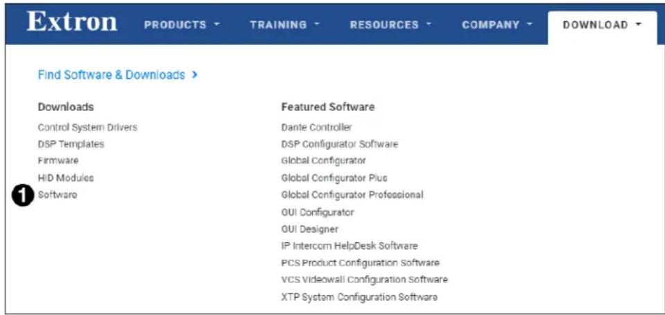
Figure 9. Extron Website Download Page
To download and install the XTP System Configuration Software from this page, perform the following:
- On the Extron website, go to the Download tab and click Software (see figure 9, 1).
TIP: If the XTP System Configuration Software is listed under "Featured Software" on the Download tab, click the XTP System Configuration Software link to go directly to the product page (see Software Product Page on the next page).
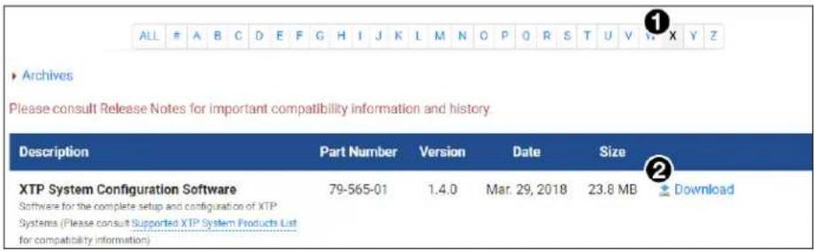
Figure 10. XTP System Configuration Software Download Link
- Click the X link (see figure 10, ①).
- Locate the XTP System Configuration Software and click the Download link (see figure 10, ②) to the right of the product name.
- Submit any required information to start the download. Note where the file is saved.
- Open the saved executable (.exe) file.
- Follow the instructions that appear on the screen to install the program.
Software Product Page
The software product page contains information about the software.
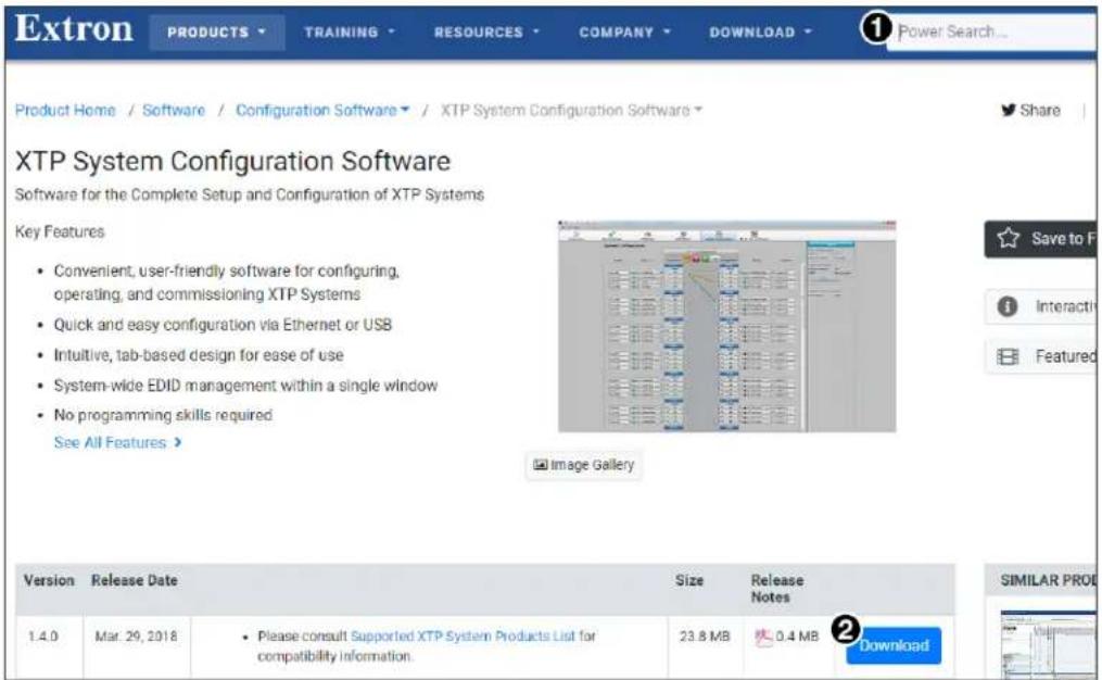
Figure 11. XTP System Configuration Software Product Page
To download and install the XTP System Configuration Software from this page, perform the following:
- In the Search field (see figure 11, ①), type XTP System Configuration Software.
- Press
on the keyboard or select XTP System Configuration Software from the drop-down menu. - Click the Download button (②).
- Submit any required information to start the download. Note where the file is saved.
- Open the saved executable (.exe) file.
- Follow the instructions that appear on the screen to install the program.
Software Connection
To connect the software directly to the XTP FT HD 4K, connect the computer running the software to the configuration connector (see figure 7, B on page 10).
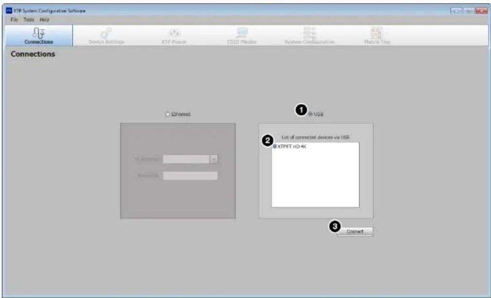
Figure 12. Connections Screen
To connect to a device:
- Open the XTP System Configuration Software. The Connections screen opens.
- From the Connections screen, select the USB radio button (see figure 12, ①).
- From the displayed list, select the connected device (②).
- Click the Connect button (③). The Device Settings screen opens (see Transmitter Configuration on page 24).
Software Operation
Menu Bar
The top menu bar contains three menus for configuring software settings.
File menu
The File menu contains options for disconnecting from the transmitter and exiting the program. To access the menu, click the File menu.
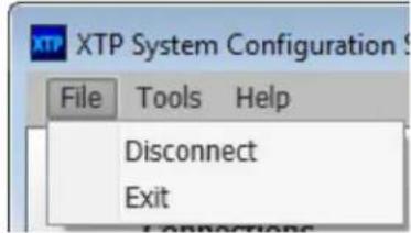
Figure 13. File Menu
Disconnect
This option disconnects the device from the XTP System Configuration Software.
From the File menu, select Disconnect. The Connections screen opens.
NOTE: If the device is already disconnected, the Disconnect option is disabled until a device is connected.
Exit
This option disconnects the transmitter from the software and closes the application.
From the File menu, select Exit to close the application.
Tools menu
The Tools menu contains an option for updating firmware. To access this menu, click the Tools menu.
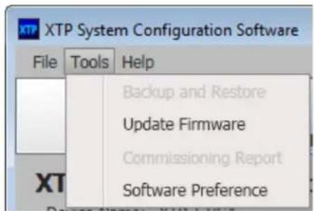
Figure 14. Tools Menu
NOTE: The Backup and Restore and Commissioning Report options are not available when directly connected to the XTP FT HD 4K (see an XTP matrix switcher user guide (www.extron.com) for more information on these features).
Update Firmware
This option uploads firmware from the host device to the connected device.
- From the Tools menu, select Update Firmware. A dialog box opens to ask permission to disconnect from the device.
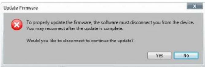
Figure 15. Confirm Disconnect Dialog Box
- Click the Yes button to disconnect from the device and continue with the firmware update process. The Update Firmware dialog box opens.
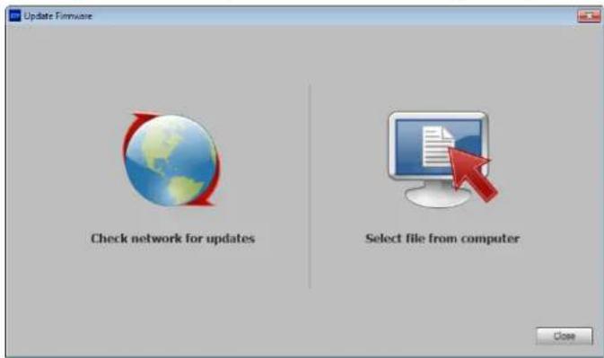
Figure 16. Update Firmware Dialog Box
-
Click one of the following options:
-
Select file from computer — Uploads a manually selected firmware file saved on the connected computer.
-
Check network for updates — Checks the connected network for firmware updates. If any are found, click the Update X Devices button to update the firmware for the applicable connected devices or click Save File to Computer to save the firmware file to the connected computer.
-
Click the Close button after the firmware finishes updating.
Software Preference
This option resets all disabled confirmation dialogs to the default settings.
- From the Tools menu, select Software Preference. The Software Preference dialog box opens.
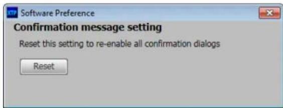
Figure 17. Software Preference Dialog Box
- Click the Reset button. The dialog box closes.
Help menu
The Help menu contains a way to access XTP System Configuration Software information, a link to the help file, and a link to the Extron website.
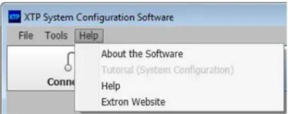
Figure 18. Help Menu
NOTE: The Tutorial (System Configuration) option is not available when the XTP System Configuration Software is directly connected to the device.
About the Software
This option provides basic information about the XTP System Configuration Software, including version number and copyright information.
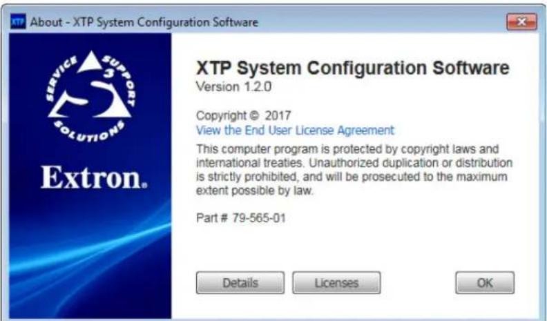
Figure 19. About - XTP System Configuration Software Dialog Box (Example)
- From the Help menu, select About the Software. The About dialog box opens.
- Click the Details button for more information.
- Click the 0k button to close the dialog box.
Help
This option opens the XTP System Configuration Software help file in a web browser.
From the Help menu, select Help.
Extron Website
This option opens the Extron website in a web browser.
From the Help menu, select Extron Website.
Transmitter Configuration
The Device Settings screen allows a user to view and edit various device settings of the transmitter connected to the host device.
Transmitter device settings
Click the Device Settings icon (see figure 20, 1) on the Global Navigation Bar to open the Device Settings screen.
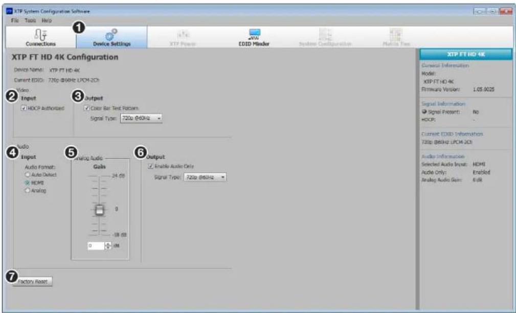
Figure 20. Transmitter Device Settings Screen
Video panel
② Video input — Select the HDCP Authorized check box to set the input as an HDCP authorized device or deselect it to indicate that the device is not an HDCP authorized device. By default, the check box is selected.
③ Video output — Select the Color Bars Test Pattern check box to transmit a test pattern to an XTP receiver or XTP matrix switcher or deselect it to stop transmitting a test pattern to an XTP receiver or XTP matrix switcher. If selected, also select a signal type from the Signal Type drop-down menu.
Audio panel
4 Audio format (see figure 20 on the previous page) — Select one of the following radio buttons to determine the audio input format:
- Auto Detect — Automatically detects the input audio format. When enabled, HDMI audio has priority over analog audio.
• HDMI — Transmits embedded audio from an HDMI signal. - Analog — Transmits an analog audio signal.
⑤ Analog audio — If applicable, move the handle of the Analog Audio Gain slider up or down or specify the desired gain in the field below the slider to adjust the audio gain or attenuation in dB.
6 Audio output — Select the Enable Audio Only check box to enable a black signal for audio-only transmission to the HDMI output connector on a connected receiver. By default, the check box is selected.
If selected, also select the black signal resolution from the Signal Type drop-down menu. The default resolution is 720p @ 60 Hz.
Factory reset
⑦ Factory Reset — Click the Factory Reset button to reset the transmitter to factory settings except for firmware (see mode 5 in Reset Modes on page 12).
NOTE: This is the same as the Esc ZXXX SIS command (see Reset mode SIS command on page 17).
Device Information panel
The Device Information panel on the right side of the software screen displays device information and settings.
① Model — Displays the device model.
② Firmware Version — Displays the full firmware version.
③ Signal Present — Indicates whether an active signal is on the input.
④ HDCP — Displays the HDCP status of an active input.
⑤ EDID — Displays the current resolution and refresh rate.
⑥ Selected Audio Input — Displays the audio format of the selected input.
⑦ Audio only — Displays whether only audio is sent to outputs.
⑧ Analog Audio Gain — Displays the gain for analog audio.
| XTP FT HD 4K | |
| General Information | |
| Model: | |
| XTP FT HD 4K | 1 |
| Firmware Version: 1.05.0025 | 2 |
| Signal Information | |
| ● Signal Present: No | 3 |
| HDCP: - | 4 |
| Current EDID Information | |
| 720p @60Hz LPCM-2Ch | 5 |
| Audio Information | |
| Selected Audio Input: HDMI | 6 |
| Audio Only: Enabled | 7 |
| Analog Audio Gain: 0 dB | 8 |
EDID Minder
Use the EDID Minder screen to assign unique EDID to the input or match current output EDID to the input. Click the EDID Minder button (see figure 21, ①) on the Global Navigation bar. The EDID Minder screen opens.
The EDID Minder screen displays a table of EDID options and connected output devices, which are each represented by output display icons.
• Factory default EDID options are displayed in blue.
- Connected output resolutions and devices are displayed in green.
- Custom loaded or saved EDID options are displayed in yellow.
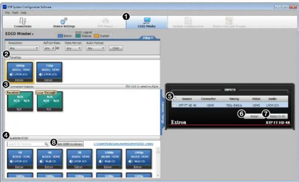
Figure 21. EDID Minder Screen
Assign EDID to the input
- Select an available EDID setting (represented by a blue, green, or yellow output display icon) from the Favorites, Connected Outputs, or Available EDID panel (2-4).
- Select the check box of the connected input ( 5).
- Click the Assign button (⑥) or the Assign to All button (⑦) below the input area.
TIP: Alternatively, EDID can be assigned by dragging and dropping the desired EDID onto the input.
Add an EDID File to the EDID Library
- In the Available EDID panel, click the Add EDID to Library button (⑧). The Browse window opens.
- Navigate to and select the desired EDID file and click Open. The EDID file appears in the Available EDID panel (4).
- Assign the EDID file from the Available EDID panel to import the EDID to the device.
Save output EDID
- Right-click on the desired EDID icon in the Connected Outputs panel (see figure 21, ③ on the previous page).
- Select the Save EDID to Library option. The EDID setting is saved to the connected PC. Alternatively, right-click on the desired EDID, select Copy, and then Paste the EDID into the Favorites or Available EDID panel.
Set favorite EDID
To add commonly used EDID settings to the Favorites panel for quick access, perform one of the following methods:
- Click and drag the desired EDID from the Connected Outputs or the Available EDID panel to the Favorites panel. The EDID setting is copied to the Favorites panel (see figure 21, ②).
- Right-click the desired EDID and select Copy. Then, Paste the EDID setting into the Favorites panel.
EDID filters
The filters (see figure 22) can be used to easily locate a specific EDID setting.

① Resolution filter
② Refresh Rate filter
③ Video Format filter
4 Audio Format filter
⑤ Clear button
Figure 22. EDID Minder Filters
To use a filter or combination of filters, perform the following:
-
Select an EDID setting from one of the drop-down lists of the associated filter (see figure 22, ①-④). The available EDID options that match the filter selection are displayed in their respective panels.
-
Repeat step 1 to apply more filters.
NOTE: To clear the currently applied filters, click the Clear button next to the filters (see figure 22, 5). All filters are reset.
Common timings
This function automatically displays available EDID settings that are common among multiple selected outputs.
- Hold
and click the desired outputs in the Connected Outputs panel. The Common Timings tab (located to the right of the Connected Outputs panel) appears, listing the EDID settings common among the selected outputs. - Select the desired common EDID. The EDID is shown in the Available EDID panel.
Reference Information
This section covers the following topics:
- Mounting
- Firmware Download
Mounting
The XTP FT HD 4K can be placed on a tabletop or mounted in a rack or underneath a desk.
Tabletop Mounting
Attach the provided rubber feet to the bottom four corners of the enclosure.
Furniture Mounting
Go to www.extron.com for a list of available furniture mounting kits. To install either device to furniture, follow the mounting kit instructions.
Rack Mounting
Go to www.extron.com for a list of compatible rack mounting kits. To install either device in a rack, follow the mounting kit instructions and see the UL guidelines for rack-mounted devices below.
UL guidelines for rack-mounted devices
The following Underwriters Laboratories (UL) guidelines pertain to the safe installation of the XTP FT HD 4K in a rack.
- Elevated operating ambient temperature — If installed in a closed or multi-unit rack assembly, the operating ambient temperature of the rack environment may be greater than room ambient temperature, Therefore, install the XTP FT HD 4K in an environment compatible with the maximum ambient temperature (Tma = +122 °F, +50 °C) specified by Extron.
- Reduced air flow — Install the equipment in a rack so that the amount of air flow required for safe operation of the equipment is no compromised.
- Mechanical loading — Mount the equipment in the rack so that a hazardous condition is not achieved due to uneven mechanical loading.
- Circuit overloading — Connect the equipment to the supply circuit and consider the effect that circuit overloading might have on overcurrent protection and supply wiring. Appropriate consideration of equipment nameplate ratings should be used when addressing this concern.
- Reliable earthing (grounding) — Maintain reliable grounding of rack-mounted equipment. Pay particular attention to supply connections other than direct connections to the branch circuit (for example, the use of power strips).
XTP FT HD 4K Fiber Transmitter • Reference Information 28
Firmware Download
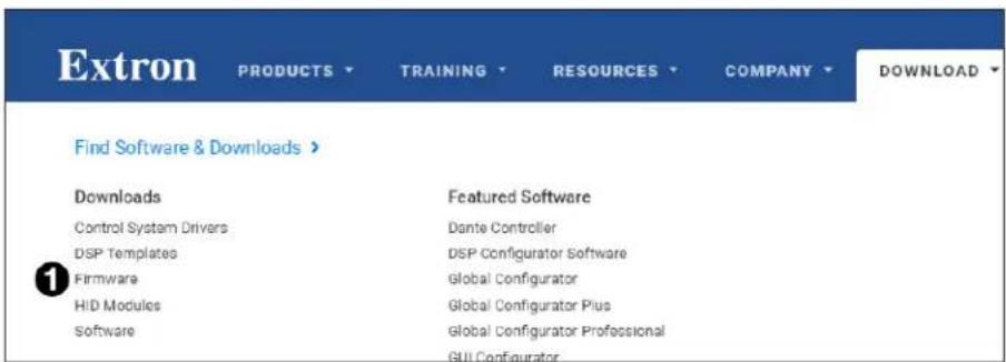
Figure 23. Downloading Firmware from the Extron Website
- On the Extron website, www.extron.com, go to the Download tab and click Firmware (see figure 23, ①).
- Navigate to the desired product (see figure 24, ②).
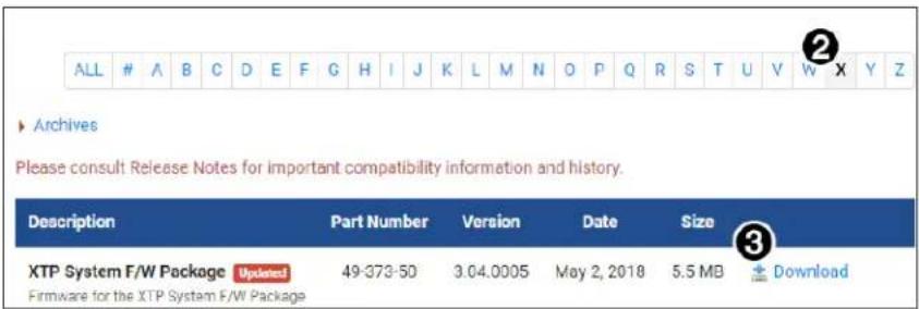
Figure 24. Downloading Firmware from the Extron Website
- Ensure the available firmware version is a later version than the current one on the device, and click the Download link (③).
NOTE: The firmware release notes are a PDF file that provides details about the changes between different firmware versions. The file can be downloaded from the same page as the firmware.
- Submit any required information to start the download. Note where the file is saved.
Extron Warranty
Extron Electronics warrants this product against defects in materials and workmanship for a period of three years from the date of purchase. In the event of malfunction during the warranty period attributable directly to faulty workmanship and/or materials, Extron Electronics will, at its option, repair or replace said products or components, to whatever extent it shall deem necessary to restore said product to proper operating condition, provided that it is returned within the warranty period, with proof of purchase and description of malfunction to:
USA, Canada, South America, and Central America:
Extron Electronics
1230 South Lewis Street
Anaheim, CA 92805
U.S.A.
Japan:
Extron Electronics, Japan
Kyodo Building, 16 Ichibancho
Chiyoda-ku, Tokyo 102-0082
Japan
Europe and Africa:
Extron Europe
Hanzeboulevard 10
3825 PH Amersfoort
The Netherlands
China:
Extron China
686 Ronghua Road
Songjiang District
Shanghai 201611
China
Asia:
Extron Asia Pte Ltd
135 Joo Seng Road, #04-01
PM Industrial Bldg.
Singapore 368363
Singapore
Middle East:
Extron Middle East
Dubai Airport Free Zone
F13, PO Box 293666
United Arab Emirates, Dubai
This Limited Warranty does not apply if the fault has been caused by misuse, improper handling care, electrical or mechanical abuse, abnormal operating conditions, or if modifications were made to the product that were not authorized by Extron.
NOTE: If a product is defective, please call Extron and ask for an Application Engineer to receive an RA (Return Authorization) number. This will begin the repair process.
USA: 714.491.1500 or 800.633.9876
Europe: 31.33.453.4040
Asia: 65.6383.4400 Japan: 81.3.3511.7655
Units must be returned insured, with shipping charges prepaid. If not insured, you assume the risk of loss or damage during shipment. Returned units must include the serial number and a description of the problem, as well as the name of the person to contact in case there are any questions.
Extron Electronics makes no further warranties either expressed or implied with respect to the product and its quality, performance, merchantability, or fitness for any particular use. In no event will Extron Electronics be liable for direct, indirect, or consequential damages resulting from any defect in this product even if Extron Electronics has been advised of such damage.
Please note that laws vary from state to state and country to country, and that some provisions of this warranty may not apply to you.
- Safety Instructions • English
- Trademarks
- FCC Class A Notice
- Class 1 Laser Product
- Conventions Used in this Guide
- Notifications
- Software Commands
- Specifications Availability
- Extron Glossary of Terms
- Contents
- Introduction.... 1
- Installation....5
- Operation....10
- SIS Configuration and Control....13
- Configuration Software....18
- Reference Information 28
- Introduction
- Guide Overview
- Product Descriptions
- Cable Transmission
- NOTES:
- Control Methods
- Features
- XTP Interconnection Features
- Video Features
- Audio Features
- Control Features
- General Features
- Installation
- Rear Panel Connectors
- Transmitter inputs
- Transmitter XTP interconnection
- Transmitter power
- Connection Details
- HDMI Connection
- ATTENTION:
- RS-232 and IR Communication
- Operation
- Transmitter Front Panel Features
- HDMI Audio Switch
- EDID
- Audio Output Overview
- Reset Modes
- SIS Configuration and Control
- Host Device Connection
- SIS Overview
- Host and Device Communication
- Error Responses
- Using the Command and Response Tables for SIS Commands
- Symbol Definitions
- Command and Response Tables
- Configuration Software
- Software Installation
- Software Download Center Page
- Software Product Page
- Software Connection
- Software Operation
- Menu Bar
- File menu
- Disconnect
- Exit
- Tools menu
- Update Firmware
- Software Preference
- Help menu
- About the Software
- Help
- Extron Website
- Transmitter Configuration
- Transmitter device settings
- Video panel
- Audio panel
- Factory reset
- Device Information panel
- EDID Minder
- Assign EDID to the input
- Add an EDID File to the EDID Library
- Save output EDID
- Set favorite EDID
- EDID filters
- Figure 22. EDID Minder Filters
- Common timings
- Reference Information
- Mounting
- Tabletop Mounting
- Furniture Mounting
- Rack Mounting
- UL guidelines for rack-mounted devices
- Firmware Download
- Extron Warranty
- USA, Canada, South America, and Central America:
- Japan:
- Europe and Africa:
- China:
- Asia:
- Middle East:
Brand : Extron
Model : XTP FT HD 4K
Category : Audiovisual Equipment