
AXI 016 - Audiovisual Equipment Extron - Free user manual and instructions
Find the device manual for free AXI 016 Extron in PDF.


| Product Type | 16-Channel Audio Power Amplifier |
| Model | AXI 016 |
| Brand | Extron |
| Channels | 16 |
| Power Output (per channel) | 60 W at 4 Ω, 30 W at 8 Ω |
| Total Power (all channels) | 960 W at 4 Ω |
| Frequency Response | 20 Hz – 20 kHz (±0.5 dB) |
| THD+N | <0.05% at 1 kHz, rated power |
| Signal-to-Noise Ratio | >100 dB |
| Input Connectors | 16 × Phoenix-style 3-pin |
| Output Connectors | 16 × Phoenix-style 4-pin |
| Control | RS-232, Ethernet, contact closure |
| Rack Mount | 19-inch, 1U height |
| Dimensions (H × W × D) | 1.7" × 17.0" × 12.0" (4.3 cm × 43.2 cm × 30.5 cm) |
| Weight | 10.5 lb (4.8 kg) |
| Power Supply | 100-240 V AC, 50/60 Hz, internal |
| Power Consumption | 1000 W maximum |
| Cooling | Variable speed fan, front-to-rear airflow |
| Protection | Short circuit, thermal, overcurrent |
| Operating Temperature | 32 °F to 104 °F (0 °C to 40 °C) |
| Compliance | UL, CE, FCC Class A |
| Warranty | 3 years parts and labor |
Frequently Asked Questions - AXI 016 Extron
User questions about AXI 016 Extron
0 question about this device. Answer the ones you know or ask your own.
Ask a new question about this device
Download the instructions for your Audiovisual Equipment in PDF format for free! Find your manual AXI 016 - Extron and take your electronic device back in hand. On this page are published all the documents necessary for the use of your device. AXI 016 by Extron.
USER MANUAL AXI 016 Extron
This guide provides basic instructions for an experienced technician to install the AXI 016 Audio Expansion Interface. The AXI 016 is a pure breakout device that provides 16 line-level outputs for EXP-enabled devices. The AXI 016 is simple to use with no DSP processing hardware controls. For additional information and specifications, go to www.extron.com.
NOTES:
- EXP-enabled devices are devices that contain an Extron EXP port for routing 16 bidirectional channels of digital audio.
- In this guide, "EXP-enabled devices" and "EXP devices" are used interchangeably.
Disconnect Power and Mount the AXI 016
Disconnect power from the AXI 016 and power off all devices that will be connected to it. The AXI 016 is housed in a half-rack width, 6-inch deep, 1U-high metal enclosure that can be rack mounted, set on a rack shelf, or placed on a table with the provided rubber feet. Select a suitable mounting location, then choose an appropriate mounting option.
Rear Panel Connections
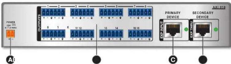
A Power Inlet
B Analog Audio Outputs
© EXP Input Port and LED
EXP Thru Port and LED
Figure 1. AXI 016 Rear Panel Connections
A 12 VDC Power Inlet — Connect the 12 VDC power supply to the rear panel captive screw power inlet. Then, plug the power cable into the IEC inlet on the external power supply (see figure 2 and the following Attention notices).
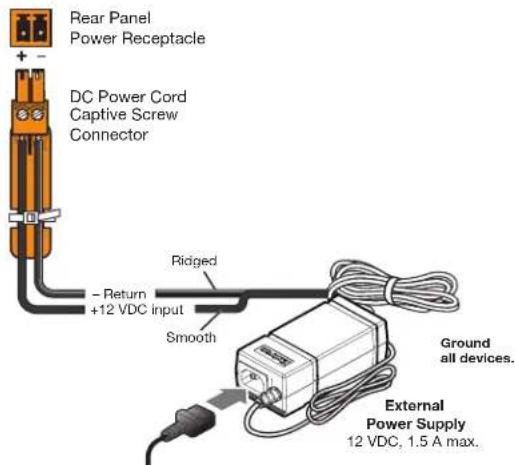
Figure 2. Connecting the External Power Supply
ATTENTION:
B Analog Audio Outputs — Use 6-pole, 3.5 mm captive screw connectors to connect up to 16 balanced or unbalanced line-level devices. Balanced or unbalanced mono devices can also be connected using 3-pole, 3.5 mm captive screw connectors.
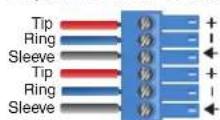
Balanced Output Unbalanced Output
6-pole Audio OUTPUT Wiring
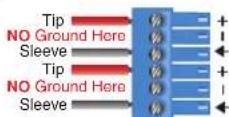
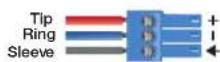
Balanced Output

Unbalanced Output
3-pole Audio OUTPUT Wiring
Figure 3. Audio Output Wiring
ATTENTION :
- For unbalanced audio outputs, connect the sleeves to the ground contact. DO NOT connect the sleeves to the negative (-) contacts.
- Pour l'audio asymétrique, connectez les manchons au contact au sol. NE PAS connecter les manchons aux contacts négatifs (-).
EXP Input Port and LED — This RJ-45 EXP port connects the AXI 016 to the EXP port of a primary EXP device. The Expansion output channels of the primary EXP device are sent to the AXI 016 line outputs (see Connecting a Primary Device to the EXP Input Port on the next page). The LED to the right of the EXP INPUT port blinks to indicate a primary EXP device is connected.
NOTE: A primary EXP device is a device that has been set as a Primary Unit in DSP Configurator (see the DMP 128 Plus User Guide for more information regarding primary and secondary EXP devices). DMP 128 Plus units are set to primary by default.
EXP Thru Port and LED — This RJ-45 EXP port connects the Expansion output channels of a secondary EXP device to the AXI 016. When a primary EXP device is connected to the EXP INPUT port, the Expansion output channels of the secondary EXP device connected to the EXP THRU port are sent through the AXI 016 to the Expansion input channels of the primary device connected to the EXP INPUT port (see Connecting a Primary EXP Device and Secondary EXP Device on page 4). If no primary EXP device is connected to the EXP INPUT port, the Expansion output channels of the secondary EXP device connected to the EXP THRU port are sent to the AXI 016 line outputs (see Connecting a Secondary EXP Device to the EXP Thru Port on page 6). The LED to the right of the EXP THRU port lights solid to indicate a secondary EXP device is connected.
NOTE: A secondary EXP device is a device that has been set as a Secondary Unit in DSP Configurator (see the DMP 128 Plus User Guide for more information regarding primary and secondary EXP devices). DTP CrossPoint units are set to secondary by default.
Front Panel Features
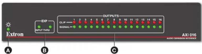
A Power Indicator LED
B EXP Indicator LEDs
© Output Signal and Clip LEDs
Figure 4. AXI 016 Front Panel Features
Power Indicator LED — This green LED lights solid when the AXI 016 is powered and fully operational.
B EXP Indicator LEDs — The green Input LED blinks to indicate a primary EXP device is connected to the rear-panel EXP INPUT port. The green Thru LED lights solid to indicate a secondary EXP device is connected to the rear-panel EXP THRU port.
C Output Signal and Clip LEDs — Sixteen pairs of stacked green and red LEDs light steadily when signal is present and increase in intensity from -60 dBFS (lowest intensity, signal presence indication) to -3 dBFS (full brightness). The red clip LEDs light solid to indicate clipping when a signal exceeds -3 dBFS. The red clip LEDs stay lit for one second after clipping ceases.
Application and Signal Flow Diagrams
The following diagrams display the different signal flows when primary and secondary EXP-enabled devices are connected to the AXI 016.
NOTE: Daisy-chaining two or more AXI 016 units together is not supported.
Connecting a Primary Device to the EXP Input Port
The diagram below displays the AXI 016 signal flow when only a primary EXP device, such as the DMP 128 Plus, is connected to the EXP INPUT port of the AXI 016.
All 16 Expansion output channels of the primary device are routed to the line outputs of the AXI 016 (see path A1 in figure 5).
• Expansion output channel 1 of the primary device is routed to the AXI 016 line output 1, and so on.
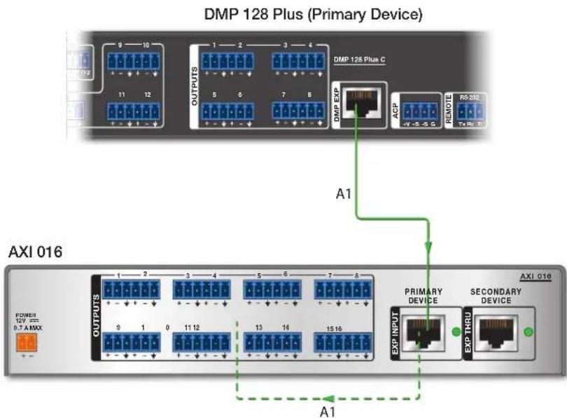
NOTE: Dotted lines represent signal flows inside the AXI 016. Solid lines represent signal flows over CAT 6 cable.
Figure 5. Basic Signal Flow from Primary EXP Device to AXI 016
Connecting a Primary EXP Device and Secondary EXP Device
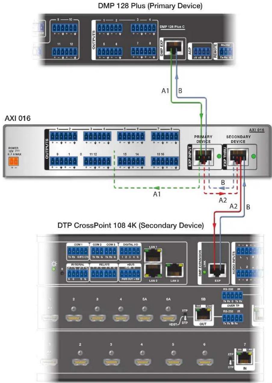
The diagram below displays the signal flow when a primary EXP-enabled device is connected to the EXP INPUT port and a secondary EXP-enabled device is connected to the EXP THRU port.
- All 16 Expansion output channels of the secondary device are routed through the AXI 016 and into the primary EXP device Expansion input channels (see path B in the figure below).
- All 16 Expansion output channels of the primary EXP device are routed to the 16 analog line outputs of the AXI 016 (see path A1 in the figure below). Expansion output channel 1 of the primary EXP device is routed to the AXI 016 line output 1, and so on.
- All 16 Expansion output channels of the primary EXP device are also routed to the Expansion input channels of the secondary EXP device (see path A2 in the figure below). Expansion output channel 1 of the secondary EXP device is routed to Expansion input channel 1 of the primary EXP device, and so on.
flowchart
graph TD
    A["DMP 128 Plus (Primary Device)"] -->|A1, B| B["AXI 016"]
    A -->|A1, B| C["DTP CrossPoint 108 4K (Secondary Device)"]
    C -->|A1, B| D["AXI 016"]
    C -->|A1, B| E["AXI 016"]
    style A fill:#f9f,stroke:#333
    style B fill:#ccf,stroke:#333
    style C fill:#cfc,stroke:#333
    style D fill:#fcc,stroke:#333
    style E fill:#cff,stroke:#333
NOTE: Dotted lines represent signal flows inside the AXI 016. Solid lines represent signal flows over CAT 6 cable.
Figure 6. Advanced Signal Flow when Primary and Secondary EXP Devices are Connected
Connecting a Secondary EXP Device to the EXP Thru Port
The diagram below displays the signal flow when only a secondary EXP device such as the DTP CrossPoint 108 4K is connected to the EXP THRU port.
- All 16 Expansion output channels of the secondary EXP device are routed to the 16 line outputs of the AXI 016. The Expansion output channels of a secondary EXP device are only routed to the AXI 016 line outputs when no primary device is connected to the EXP INPUT port (see Connecting a Primary EXP Device and Secondary EXP Device on the previous page).
• Expansion output channel 1 of the secondary EXP device is routed to the AXI 016 line output 1, and so on.
AXI 016
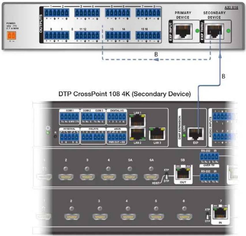
NOTE: Dotted lines represent signal flows inside the AXI 016. Solid lines represent signal flows over CAT 6 cable.
Figure 7. Basic Signal Flow from Secondary EXP Device to AXI 016
For information on safety guidelines, regulatory compliances, EMI/EMF compatibility, accessibility, and related topics, see the Extron Safety and Regulatory Compliance Guide on the Extron website.
- NOTES:
- Disconnect Power and Mount the AXI 016
- Rear Panel Connections
- ATTENTION:
- ATTENTION :
- Front Panel Features
- Application and Signal Flow Diagrams
- Connecting a Primary Device to the EXP Input Port
- Connecting a Primary EXP Device and Secondary EXP Device
- Connecting a Secondary EXP Device to the EXP Thru Port
Brand : Extron
Model : AXI 016
Category : Audiovisual Equipment