
DSC HD-HD 4K PLUS A xi - Audiovisual Equipment Extron - Free user manual and instructions
Find the device manual for free DSC HD-HD 4K PLUS A xi Extron in PDF.


| Product Type | HDMI to HDMI 4K Scaler |
| Model | DSC HD-HD 4K PLUS A xi |
| Brand | Extron |
| Input Connectors | 2 x HDMI (female) |
| Output Connectors | 2 x HDMI (female) |
| Max Video Resolution | 4096x2160 @ 60 Hz (4:4:4) |
| Video Bandwidth | Up to 18 Gbps |
| HDCP Compliance | HDCP 1.4 and 2.2 |
| Audio Input | 2-channel analog on 5-pole captive screw connector |
| Audio Output | 2-channel analog on 5-pole captive screw connector |
| Embedded Audio | HDMI audio embedding and de-embedding (LPCM 2.0) |
| Control Ports | RS-232 (rear), USB (front), Ethernet RJ-45 |
| Scaling Engine | Extron Vector 4K with 30-bit precision |
| Video Processing | Motion-adaptive deinterlacing up to 1080i, 3:2/2:2 pulldown |
| EDID Management | EDID Minder™ with auto and custom modes |
| Frame Lock | Accu-RATE Frame Lock (AFL) technology |
| Auto-Image | One-touch automatic image optimization |
| Test Patterns | Built-in (color bars, crosshatch, grayscale, etc.) |
| On-Screen Display | Full OSD menu system via front panel buttons |
| Front Panel Lock | Executive Mode for security |
| Power Supply | Internal, 100-240 VAC, 50-60 Hz |
| Enclosure | 1U high, half rack width, 9.5" deep (24 cm) |
| Safety | FCC Class A, CE compliant |
| Cleaning | Wipe with dry, soft cloth. Do not use liquids. |
| Warranty | 3 years (parts and labor) |
Frequently Asked Questions - DSC HD-HD 4K PLUS A xi Extron
User questions about DSC HD-HD 4K PLUS A xi Extron
0 question about this device. Answer the ones you know or ask your own.
Ask a new question about this device
Download the instructions for your Audiovisual Equipment in PDF format for free! Find your manual DSC HD-HD 4K PLUS A xi - Extron and take your electronic device back in hand. On this page are published all the documents necessary for the use of your device. DSC HD-HD 4K PLUS A xi by Extron.
USER MANUAL DSC HD-HD 4K PLUS A xi Extron
DSC HD-HD 4K A Series
HDMI to HDMI 4K Scalers
Safety Instructions
Safety Instructions • English
WARNING: This symbol, , when used on the product, is intended to alert the user of the presence of uninsulated dangerous voltage within the product's enclosure that may present a risk of electric shock.
ATTENTION: This symbol, when used on the product, is intended to alert the user of important operating and maintenance (servicing) instructions in the literature provided with the equipment.
For information on safety guidelines, regulatory compliances, EMI/EMF compatibility, accessibility, and related topics, see the Extron Safety and Regulatory Compliance Guide, part number 68-290-01, on the Extron website, www.extron.com.
© 2016 Extron Electronics. All rights reserved.
Trademarks
All trademarks mentioned in this guide are the properties of their respective owners.
The following registered trademarks®, registered service marks ^(SM) , and trademarks ^(TM) are the property of RGB Systems, Inc. or Extron Electronics (see the current list of trademarks on the Terms of Use page at www.extron.com):
| Registered Trademarks ^(3) |
| Extron, AVTrac, Cable Cubby, ControlScript, CrossPoint, DTP, eBUS, EDID Manager, EDID Minder, Flat Field, FlexOS, Global Configurator, Global Scripter, GlobalViewer, Hideaway, Inline, IP Intercom, IP Link, Key Minder, LinkLicense, LockIt, MediaLink, MediaPort, NetPA, PlenumVault, PoleVault, PowerCage, PURE3, Quantum, SoundField, SpeedMount, SpeedSwitch, System INTEGRATOR, TeamWork, TouchLink, V-Lock, VersaTools, VN-Matrix, VoiceLift, WallVault, WindoWall, XTP, and XTP Systems |
| Registered Service Mark ^(SM) : S3 Service Support Solutions |
| Trademarks ^(TM) |
| AAP, AFL (Accu-Rate Frame Lock), ADSP (Advanced Digital Sync Processing), Auto-Image, CableCover, CDRS (Class D Ripple Suppression), DDSP (Digital Display Sync Processing), DMI (Dynamic Motion Interpolation), Driver Configurator, DSP Configurator, DSVP (Digital Sync Validation Processing), eLink, Entwine, EQIP, FastBite, FOX, FOXBOX, IP Intercom HelpDesk, MAAP, MicroDigital, Opti-Torque, ProDSP, QS-FPC (QuickSwitch Front Panel Controller), Room Agent, Scope-Trigger, ShareLink, SIS, Simple Instruction Set, Skew-Free, SpeedNav, Triple-Action Switching, True4K, Vector ^TM 4K , WebShare, XTRA, ZipCaddy, and ZipClip |
FCC Class A Notice
This equipment has been tested and found to comply with the limits for a Class A digital device, pursuant to part 15 of the FCC rules. The Class A limits provide reasonable protection against harmful interference when the equipment is operated in a commercial environment. This equipment generates, uses, and can radiate radio frequency energy and, if not installed and used in accordance with the instruction manual, may cause harmful interference to radio communications. Operation of this equipment in a residential area is likely to cause interference. This interference must be corrected at the expense of the user.
NOTES: For more information on safety guidelines, regulatory compliances, EMI/EMF compatibility, accessibility, and related topics, see the “Extron Safety and Regulatory Compliance Guide” on the Extron website.
Battery Notice
This product contains a battery. Do not open the unit to replace the battery. If the battery needs replacing, return the entire unit to Extron (for the correct address, see the Extron Warranty section on the last page of this guide).
CAUTION: Risk of explosion. Do not replace the battery with an incorrect type. Dispose of used batteries according to the instructions.
Conventions Used in this Guide
Notifications
The following notifications are used in this guide:
CAUTION: Risk of minor personal injury.
NOTE: A note draws attention to important information.
TIP: A tip provides a suggestion to make working with the application easier.
Software Commands
Commands are written in the fonts shown here:
^AR Merge Scene,,∅p1 scene 1,1 ^B 51 ^W^C.∅ [∅1] R∅∅4∅03∅0∅04∅0∅08∅0∅06∅[∅2] 35 [17] [∅3]
Esc X1 * X17 * X20 * X23 * X21 CE ←
NOTE: For commands and examples of computer or device responses used in this guide, the character “∅” is used for the number zero and “O” is the capital letter “o.”
Computer responses and directory paths that do not have variables are written in the font shown here:
Reply from 208.132.180.48: bytes=32 times=2ms TTL=32 C:\Program Files\Extron
Variables are written in slanted form as shown here:
ping xxx.xxx.xxx.xxx -t SOH R Data STX Command ETB ETX
Selectable items, such as menu names, menu options, buttons, tabs, and field names are written in the font shown here:
From the File menu, select New. Click the OK button.
Specifications Availability
Product specifications are available on the Extron website, www.extron.com.
Extron Glossary of Terms
A glossary of terms is available at http://www.extron.com/technology/glossary.aspx.
Contents
Introduction.... 1
About This Guide....1
About the DSC HD-HD 4K A Series ....1
Features 2
Application Diagrams......5
Installation....6
Rear Panel Features 6
Connecting for 4K Processing .... 10
Single Input to Single Output 10
Single Input to Dual Outputs (xi Model Only)....11
Two Input Columns to a Single Output (xi Model Only)....12
Single Input to Two Output Columns (xi Model Only)....12
Two Inputs to Two Side-by-Side Outputs (xi Model Only)....13
Securing the HDMI Connector Using the LockIt Cable Lacing Bracket ....14
Connecting for Remote Control 14
Connecting to the RS-232 Port 14
Connecting to the USB Config Port ..... 15
Operation....18
Front Panel Features....18
On-screen Display Menu 19
Menu Overview....19
Using the Front Panel Buttons with the OSD Menu 20
Using the OSD Menu....21
Quick Setup Submenu.... 22
Picture Controls Submenu....23
Input Submenu....25
Output Submenu....28
Audio Submenu....32
Advanced Submenu 34
Communications Submenu 36
Device Info Screen....38
Auto-Image 38
Changing the Output Resolution and Refresh Rate 39
Custom Rates 39
Resetting the Output Rate 39
Power Save Mode....40
Presets....40
Auto Memories 40
Input Presets 41
Locking the Front Panel (Executive Mode) ..... 41
Resetting....42
Remote Configuration and Control....43
SIS Commands 43
Copyright Information 43
DSC-initiated Messages 44
Error Responses....45
Using the Command and Response Table .... 45
Symbol Definitions 46
Command and Response Table for SIS Commands 54
Product Configuration Software (PCS) Program 74
Downloading the PCS Software from the Website 74
Starting the Configuration Program....76
Updating Firmware 78
DSC HD-HD 4K A Series Web Page....79
Accessing the Web Page....79
Web Page Components 80
Special Characters 85
Mounting 86
Introduction
This section provides an overview of the DSC HD-HD 4K A series scalers, covering the following topics:
- About This Guide
• About the DSC HD-HD 4K A Series - Features
• Application Diagrams
About This Guide
The DSC HD-HD 4K A Series User Guide describes the Extron DSC HDMI-to-HDMI Digital Scaling Converters and provides instructions for experienced installers to install, configure, and operate them.
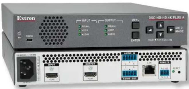
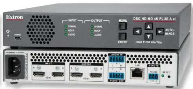
In this guide, the terms “scaler,” “DSC,” and “DSC HD-HD 4K A Series” are used interchangeably to refer to any of the DSC HD-HD 4K A series models. The term “PLUS models” refers to both the DSC HD-HD 4K PLUS A and DSC HD-HD 4K Plus A xi.
About the DSC HD-HD 4K A Series
The Extron DSC HD-HD 4K A, DSC HD-HD 4K PLUS A, and DSC HD-HD PLUS A xi are high performance, HDCP 2.2-compliant scalers capable of converting between HDMI resolutions up to 4K with full 4:4:4 signal processing and 4K @ 60 Hz with 4.2.0. They feature HDMI 2.0 connections that support data rates up to 18 Gbps (PLUS models) or 8.91 Gbps (non-PLUS model). All models incorporate the Extron-exclusive Vector 4K scaling engine, specifically engineered for critical-quality 4K applications. The two PLUS models support 4K @ 60 Hz signals at 4:4:4 on a single connection, with the DSC HD-HD 4K PLUS A xi also supporting 4K @ 60 Hz signals as columns using two connections. The DSC HD-HD 4K A (non-PLUS) model supports 4K @ 30 Hz signals at 4:4:4 and 4K @ 60 Hz at 4:2:0, on a single connection.
The scalers feature on-screen displays, stereo audio embedding and de-embedding, internal test patterns, and the ability to display custom images and logos for on-screen corporate branding and messaging. Remote configuration is available via USB and Ethernet, while external control is available through RS-232 and Ethernet.
The DSC HD-HD 4K A Series provides deinterlacing of all interlaced signals up to 1080i, automatic 3:2 and 2:2 pull down detection, and Deep Color Processing, and are compatible with all DVI or HDMI display devices. The Vector 4K scaling engine provides high-performance scaling with 30-bit precision processing and 4:4:4 color sampling, as well as downscaling of 4K source signals for interoperability with lower resolution displays or system components. Audio integration capabilities include discrete, selectable output analog and digital audio muting, analog input gain and attenuation, and output volume control. They also include a two-channel analog audio input for embedding audio onto the HDMI output and a two-channel analog audio output for sending de-embedded audio to a sound system or other audio destination.
All models are housed in 1U high by one-half rack wide by 9.5 inches (24 cm) deep enclosures and can be rack or furniture mounted.
Features
- HDMI video cross conversion — The DSC HD-HD 4K series scalers provide high quality scaling and conversion of HDMI video resolutions and frame rates.
- Advanced 4:4:4 signal processing — 4:4:4 signal processing for enhanced color accuracy and fine picture detail.
-
Inputs —
-
Video — One HDMI input for DSC HD-HD 4K A and DSC HD-HD 4K PLUS A, and two HDMI inputs for DSC HD-HD 4K PLUS A xi.
- Audio — Embedded digital audio on HDMI inputs and analog audio input on a 5-pole captive screw connector.
- Outputs —
• Video — One HDMI output for DSC HD-HD 4K A and DSC HD-HD 4K PLUS A, and two HDMI outputs for DSC HD-HD 4K PLUS A xi.
- Audio — Embedded digital audio on HDMI outputs and analog audio output on a 5-pole captive screw connector.
- Accepts HDMI video from 480i up to 4096x2160.
• DSC HD-HD 4K A — Up to 4096x2160 @ 30 Hz and up to 4096x2160 @ 60 Hz at 4:2:0.
• DSC HD-HD 4K PLUS A models — Up to 4096x2160 @ 60 Hz at 4:4:4.
- Supports single path and dual path 4K signals (DSC HD-HD 4K PLUS A xi only) — The DSC HD-HD 4K Plus A xi model delivers up to 4K/60 video as a single output or as two columns from a video source such as a workstation PC, to a display, such as a large-venue projector.
- Distribution amplifier mode (xi model only) — The second output of the DSC HD-HD 4K PLUS A xi can provide a duplicate of the primary output, allowing a source to be scaled and presented simultaneously on two separate displays without the need for a distribution amplifier.
- Advanced Extron Vector 4K scaling engine — The Vector 4K scaling engine is specifically designed for quality-critical 4K imagery, with best-in-class image upscaling and downscaling.
- Motion-adaptive deinterlacing for signals up to 1080i — Advanced deinterlacing for all interlaced signals up to 1080i delivers optimized image quality.
- Displays user-supplied images for screen saver, corporate branding, logo insertion, and HDCP notification — Custom user-loaded images can be displayed as a screen saver for a predefined duration of inactivity at the video input, or whenever the input is disconnected between presentations. User-supplied images can also be displayed for HDCP Visual Confirmation, whenever HDCP-encrypted content is transmitted to a non-HDCP compliant display.
- Logo image keying and display — A logo graphic may be placed at any position on the video output as a foreground image. Logo graphics in BMP, JPG, PNG, or TIFF format may be uploaded to the unit. Full screen images up to 4K resolution can also be displayed to eliminate blank screens between presentations.
- HDCP 1.4 and 2.2 compliant — Ensures display of content-protected media and interoperability with other HDCP-compliant devices.
- HDMI audio embedding — Audio from the two-channel analog input can be embedded onto the HDMI output.
- HDMI audio de-embedding — Embedded HDMI two-channel PCM audio can be extracted to the analog output.
- User-selectable HDCP authorization — Allows the unit to appear HDCP compliant or non-HDCP compliant to the connected source, which is beneficial if the source automatically encrypts all content when connected to an HDCP-compliant device. Protected material is not passed in non-HDCP mode.
- Supported HDMI 2.0 specification features include data rates up to 18 Gbps (PLUS models) and up to 8.91 Gbps (non-PLUS model), Deep Color, and HD lossless audio formats.
- EDID Minder automatically manages EDID communication between connected devices — EDID Minder ensures that the source powers up properly and reliably outputs content for display.
- Supports custom EDID and output resolutions — Three user-defined scaling output resolutions can be supported by uploading custom EDID files, or capturing EDID from a display or other destination device.
- Aspect ratio control — The aspect ratio of the video output can be controlled by selecting a fill mode, which provides a full screen output, or a follow mode, which preserves the original aspect ratio of the input signal.
- HDCP authentication and signal presence confirmation — Provides real-time verification of HDCP status for the digital video input and output. This allows for quick signal and HDCP verification through front panel LEDs, RS-232, USB, or Ethernet, providing feedback to a system operator or help desk support staff.
- HDCP Visual Confirmation — A full-screen green signal or a user-supplied image file is displayed when HDCP-encrypted content is transmitted to a non-HDCP compliant display, providing immediate visual confirmation that protected content cannot be viewed on the display.
- HDMI to DVI Interface Format Correction — Automatically enables or disables embedded audio and InfoFrames, and sets the correct color space for proper connection to HDMI and DVI displays.
- Accu-RATE Frame Lock (AFL) — A patented technology exclusive to Extron that locks the output frame rate to the input to eliminate stuttering caused by frame rate conversion.
- Front panel LEDs for video, HDCP, and audio presence plus power — Provide visual indication of system status for real-time feedback and monitoring of key performance parameters.
- Image freeze control — A live image can be frozen using RS-232 serial control, USB, or Ethernet control.
- Auto-Image setup — When Auto-Image is activated, the unit automatically optimizes the image by analyzing and adjusting to the video input signal. This is useful in setting up a newly connected source, particularly in presentation environments where different guest presenter laptops with various output resolutions will be connected.
- Auto Input Memory — When auto memory is activated, the unit stores size, position, and picture settings based on the incoming signal. When the same signal is detected again, these image settings are recalled from memory.
- On-screen menus — OSD menus enable system setup from the front panel controls. Key parameters such as input and output video formats are grouped on the initial Quick Setup screen, while additional screens provide full control over other unit functions and settings.
- Output Standby Mode — The unit can be set to automatically mute video and sync output to the display device when no active input signal is detected. This allows the projector or flat-panel display to automatically enter into standby mode to save energy and enhance lamp or panel life.
- Power Save Mode — The unit can be placed in a low power standby state to conserve energy when not in use.
- Automatic 3:2 and 2:2 pulldown detection — Film mode processing techniques help maximize image quality for NTSC, PAL, and 1080i sources that originated from film.
- Picture controls for brightness, contrast, detail, horizontal and vertical positioning, overscan, and sizing.
- Input presets — User memory presets are available for each input to store and recall optimized image settings.
- Internal video test patterns and pink noise generator for calibration and setup — The unit offers several video test patterns and audio pink noise to facilitate proper system setup and calibration of display devices.
- Automatic input cable equalization — Actively conditions incoming HDMI signals to compensate for signal loss when using long cables, low quality cables, or source devices with poor signal output.
- Output volume control — Provides master volume control for the analog and HDMI embedded audio outputs.
- Audio input gain and attenuation — Gain and attenuation can be adjusted for the analog audio input.
- Integrated audio delay — The audio output is automatically delayed to compensate for latency introduced by the video processing.
- Selectable audio muting — Incoming analog and HDMI embedded audio can be muted. The audio can also be muted for the analog audio and HDMI outputs.
- Front panel security lockout — Locks out all front panel functions except for input selection. (All functions, however, are available through Ethernet, USB, or RS-232 control.)
- Ethernet monitoring and control — Enables control and proactive monitoring over a LAN or WAN. An intuitive web interface is included for system monitoring and firmware updates.
- Built-in web pages — Enable the use of a standard browser for monitoring, troubleshooting, and firmware upgrades over an intuitive web interface.
- RS-232 control port — Enables the use of serial commands for integration into a control system. Extron products use the SIS (Simple Instruction Set) command protocol, a set of basic ASCII commands that enable programming of the unit.
- USB configuration port — The front panel USB Config port enables configuration without having to access the rear panel.
- Product Configuration Software (PCS) — Enables configuration of multiple products using a single software application.
• 1U, half rack width metal enclosure. - LockIt HDMI cable lacing brackets provided.
- Internal universal power supply — The 100-240 VAC, 50-60 Hz, international power supply provides worldwide power compatibility with high demonstrated reliability.
Application Diagrams
flowchart
graph TD
    A["Extron DSC HD-HD 4K PLUS A"] -->|HDMI 4K| B["Extron DTP HDMI 4K 4K"]
    A -->|HDMI 1080p| C["Extron DTP HDMI 4K 330 Rx Receiver"]
    A -->|HDMI 4K| D["Extron SM 26 Surface Mount Speakers"]
    A -->|HDMI 4K| E["Blu-ray Player"]
    A -->|HDMI 1080p| F["Laptop"]
    A -->|HDMI 4K| G["Workstation PC"]
    A -->|CATx Cable up to 330' (100 m)| H["Extron DTP HDMI 4K 330 Rx Receiver"]
    A -->|CATx Cable up to 330' (100 m)| I["Extron SM 26 Surface Mount Speakers"]
    A --> J["Audio"]
    A --> K["4K Display HDMI 4K"]
    style A fill:#f9f,stroke:#333
    style B fill:#ccf,stroke:#333
    style C fill:#cfc,stroke:#333
    style D fill:#fcc,stroke:#333
    style E fill:#cff,stroke:#333
    style F fill:#ffc,stroke:#333
    style G fill:#cfc,stroke:#333
    style H fill:#fcc,stroke:#333
    style I fill:#cfc,stroke:#333
    style J fill:#fcc,stroke:#333
    style K fill:#cfc,stroke:#333
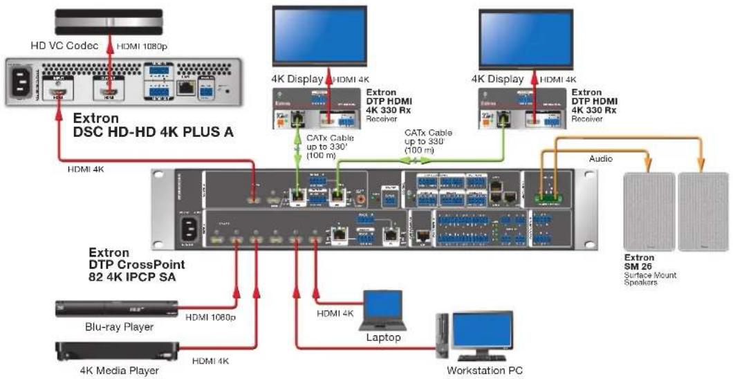
Figure 1. DSC HD-HD 4K PLUS A Application Example
flowchart
graph TD
    A["Workstation PC"] -->|HDMI 1920x2160 @ 60 Hz| B["Extron DSC HD-HD 4K PLUS A xi"]
    B -->|HDMI 3840x2160 @ 60 Hz with Audio| C["HDMI"]
    B -->|HDMI 3840x2160 @ 60 Hz with Audio| D["HDMI"]
    B -->|HDMI 3840x2160 @ 60 Hz with Audio| E["HDMI"]
    B -->|HDMI 3840x2160 @ 60 Hz with Audio| F["HDMI"]
    B -->|HDMI 3840x2160 @ 60 Hz with Audio| G["HDMI"]
    B -->|HDMI 3840x2160 @ 60 Hz with Audio| H["HDMI"]
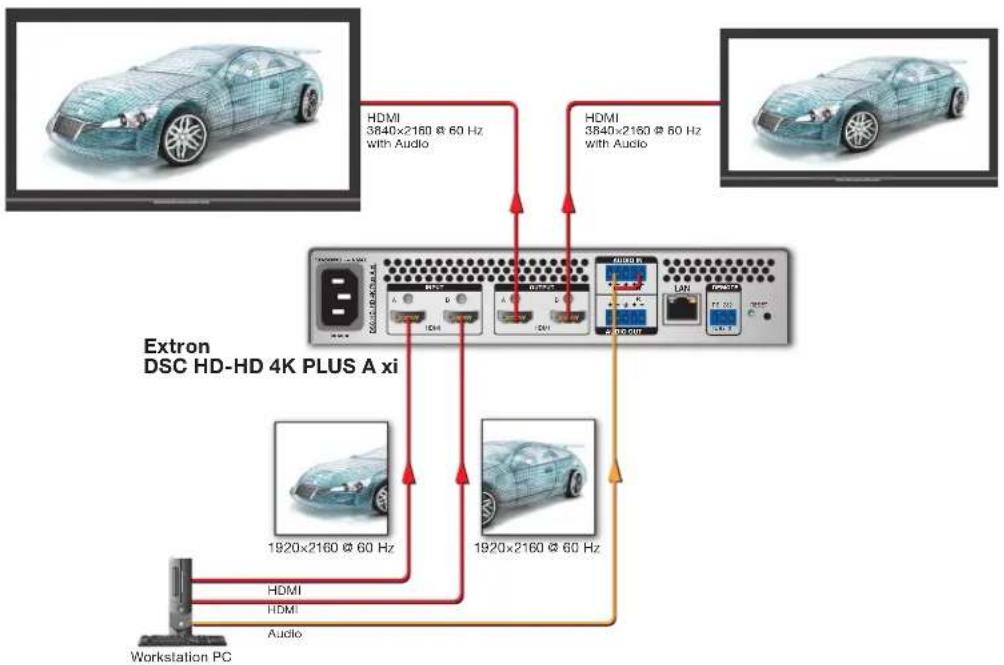
Figure 2. DSC HD-HD 4K PLUS A xi Application Example
Installation
This section provides a description of the DSC HD-HD 4K A Series rear panel connectors and instructions for cabling. Topics include:
- Rear Panel Features
- Connecting for 4K Processing
• Securing the HDMI Connector Using the LockIt Bracket - Connecting for Remote Control
ATTENTION:
The DSC HD-HD 4K A Series consists of three models:
• DSC HD-HD 4K A — One input and one output
• DSC HD-HD 4K PLUS A — One input and one output
• DSC HD-HD 4K PLUS A xi — Two inputs and two outputs
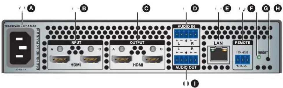
On the next page, figure 3 shows the rear panel of the standard model and figure 4 shows the rear panel of the xi model.
CAUTION: Remove power from the system before making any connections.
A AC power connector
F Remote RS-232 connector
B HDMI input connector
G Reset LED
© HDMI output connector
H Reset button
D Audio input connector
Audio output connector
E Ethernet LAN connector
Figure 3. Rear Panel, DSC HD-HD 4K PLUS A
NOTE: The rear panel of the DSC HD-HD 4K A is identical to that of the DSC HD-HD 4K PLUS A except for the product name, displayed vertically to the right of the power connector.
A AC power connector
F Remote RS-232 connector
B HDMI input connectors
G Reset LED
© HDMI output connectors
H Reset button
Audio input connector
Audio output connector
E Ethernet LAN connector
Figure 4. Rear Panel, DSC HD-HD 4K PLUS A xi
AC power connector — Connect the supplied US standard IEC power cable between this IEC connector and a 110-220 V 50-60 Hz AC power source. The front panel control and input selection buttons light in sequence during power-up.
B HDMI input connectors — These inputs accept DVI and HDMI signals with or without HDCP 1.4 or 2.2. You can enable or disable HDCP authorization using the OSD menu system (see Input Submenu on page 25), SIS commands (see HDCP Authorized commands on page 55), or the PCS software (see the DSC HD-HD 4K A Series help file) for more information.
- DSC HD-HD 4K A and DSC HD-HD 4K PLUS A — Connect an HDMI source to this female HDMI connector.
- DSC HD-HD 4K PLUS A xi — Connect one or two cables from an HDMI source to one or both of these female HDMI connectors.
Secure the HDMI output cable to the HDMI connector using the LockIt bracket (see Securing the HDMI Connector Using the LockIt Cable Lacing Bracket on page 14).
C HDMI output connectors — These outputs display the scaled video signals, support embedded digital audio signals, and are HDCP compliant. The xi model can output two identical signals, or can output column 4K modes (see Connecting for 4K Processing on page 10 for more information).
- DSC HD-HD 4K A and DSC HD-HD 4K PLUS A — Connect an HDMI output device to this female HDMI connector.
- DSC HD-HD 4K PLUS A xi — Connect one or two cables to one or both of these female HDMI connectors from an output device.
Secure the HDMI output cable to the HDMI connector using the LockIt bracket (see Securing the HDMI Connector Using the LockIt Cable Lacing Bracket).
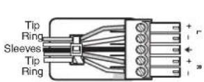
D Audio input connector — If desired, connect a 2-channel balanced or unbalanced analog audio source to this 5-pole captive screw connector to embed analog audio in the HDMI output signal. Input gain range is -18 dB to +24 dB. The default is 0 dB.
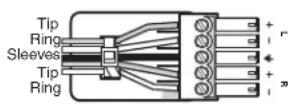
Balanced Stereo Input
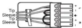
Unbalanced Stereo Input

Do not tin the wires!
Figure 5. Wiring the Audio Input Connector
ATTENTION:
Ethernet LAN connector — Plug an Ethernet cable into this RJ-45 jack to connect the unit to a computer network. Ethernet control allows you to configure and control the DSC from a remote location using SIS commands, the PCS software, or the embedded web pages. When connected to an Ethernet LAN, the DSC can be accessed from a computer running a standard Internet browser. Use a patch or crossover cable to connect the DSC to a switch, router, or computer.
The LAN connector contains two LEDs (see the illustration at right):

- Act LED — This amber LED blinks to indicate LAN signal activity.
- Link LED — This green LED lights steadily to indicate a LAN connection.
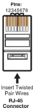
| Pin | End 1 End Wire color | 2 Wire color |
| 1 | White-green | White-orange |
| 2 | Green | Orange |
| 3 | White-orange | White-green |
| 4 | Blue | Blue |
| 5 | White-blue | White-blue |
| 6 | Orange | Green |
| 7 | White-brown | White-brown |
| 8 | Brown | Brown |
A cable that is wired as T568A at one end and T568B at the other (Tx and Rx pairs reversed) is a "crossover" cable.
| Straight-through Cable | ||
| Pin | End 1 End 2 Wire color | Wire color |
| 1 | White-orangeWhite-orange | |
| 2 | OrangeOrange | |
| 3 | White-greenWhite-green | |
| 4 | Blue | Blue |
| 5 | White-blue | White-blue |
| 6 | GreenGreen | |
| 7 | White-brown | White-brown |
| 8 | Brown | Brown |
A cable that is wired the same at both ends is called a "straight-through" cable, because no pin or pair assignments are swapped.
Figure 6. Connecting to the LAN Port
F Remote RS-232 connector — For serial RS-232 control, connect a host computer or control system to this 3-pole captive screw connector (see Connecting for Remote Control on page 14).
G Reset LED — This green LED remains lit while the DSC has power. While the Reset button (H) is being pressed and held, this LED blinks every 3 seconds to indicate the level of reset that will be initiated if the button is released at that point (see Resetting on page 42 for more information).
Reset button — This recessed button initiates levels (modes) of reset on the DSC. To initiate the different reset levels, use a pointed object such as a small Philips screwdriver or a stylus to press and hold the button while the DSC is running or while it is being powered up (see Resetting).
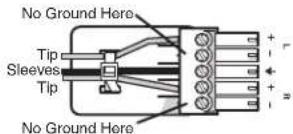
Audio output connector — Connect an amplifier or other audio output device to this 5-pole captive screw connector for analog output as shown in figure 7.
Balanced Audio Output
Unbalanced Audio Output
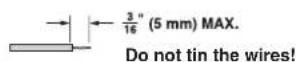
Figure 7. Wiring the Audio Output Connector
ATTENTION:
Connecting for 4K Processing
Input and output connections to the DSC HD-HD 4K A Series can vary depending on the capability of your source or sink to process signals at 4K resolution on one cable.
Single Input to Single Output
For a single-input to single-output configuration, the 4K source or sink must be capable of passing a 4K signal on a single cable (see the example in figure 8).
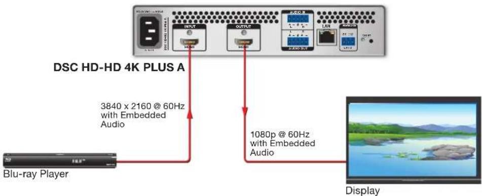
Figure 8. Single 4K Video Input to Single Output
If the sink will be displaying output at 4K as well, it must also be capable of receiving a 4K signal on a single cable.
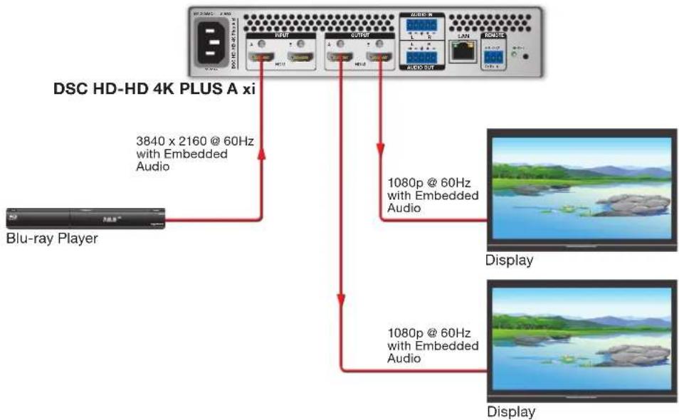
Single Input to Dual Outputs (xi Model Only)
If you are connecting a source to two sinks, the same image is displayed on both output devices (see the example in figure 9).
flowchart
graph TD
    A["Blu-ray Player"] -->|3840 x 2160 @ 60Hz with Embedded Audio| B["DSC HD-HD 4K PLUS A xi"]
    B -->|1080p @ 60Hz with Embedded Audio| C["Display"]
    B -->|1080p @ 60Hz with Embedded Audio| D["Display"]
Figure 9. Single Input (4K Video) to Two Output Devices
NOTE: If the 4K source or the 4K sink device supports 4K signals using right and left columns, connect the inputs and outputs as shown in figures 10 and 11 on the next page to process 4K video.
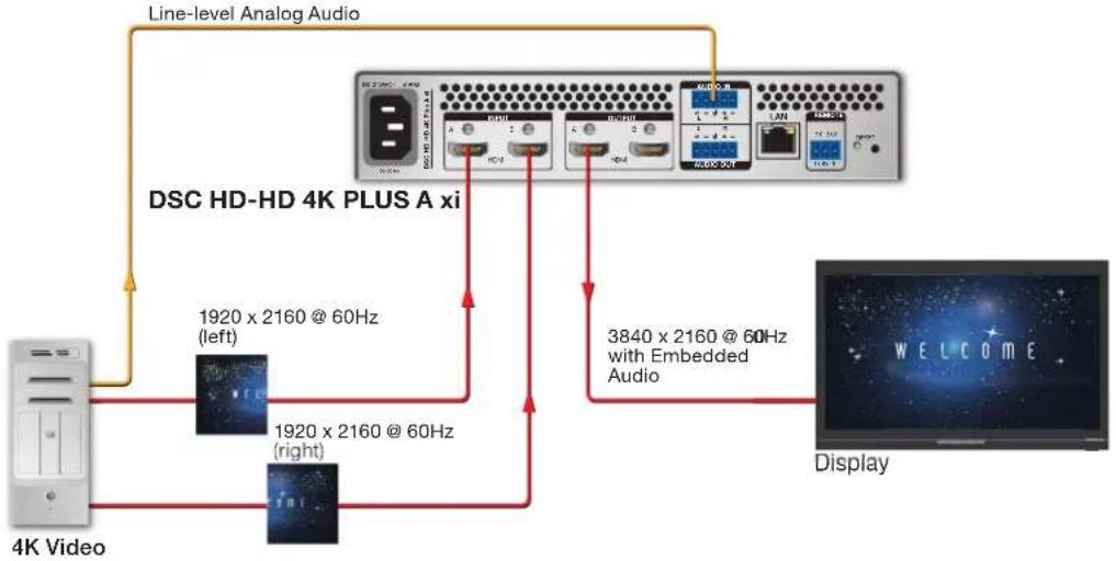
Two Input Columns to a Single Output (xi Model Only)
Input signals can be received over two wires in a "column" configuration (left and right 1920x2160 or 2048x2160 columns) and processed as a single 4K image. The left signal column is sent through a cable from the source device to DSC Input A, and the right column through a second cable to DSC Input B. The DSC combines the two input signal columns into one signal, then displays a single scaled output to output A or to outputs A and B (see the example in figure 10).
flowchart
graph TD
    A["4K Video"] -->|1920 x 2160 @ 60Hz (left)| B["DSC HD-HD 4K PLUS A xi"]
    A -->|1920 x 2160 @ 60Hz (right)| C["Display"]
    B -->|3840 x 2160 @ 60Hz with Embedded Audio| C
    C -->|Line-level Analog Audio| B
Figure 10. Left and Right Columns of 4K Video Input to a Single Output
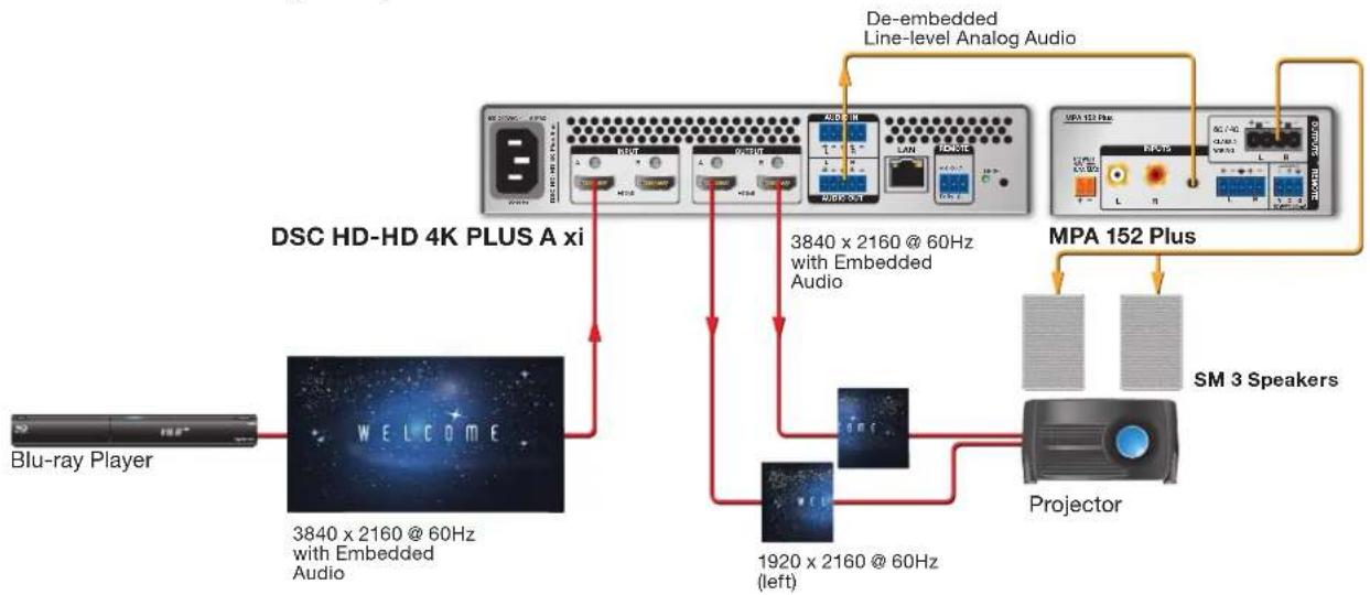
Single Input to Two Output Columns (xi Model Only)
Output signals can be sent over two wires in a split, "column" configuration (left and right 1920x2160 or 2048x2160 columns). The left column (the left half of the image) is sent to the sink through a cable connected between output A and the sink, while the right column is passed to the sink through another cable connected to output B. The sink then combines the two columns and displays them as a single image (see the example in figure 11).
flowchart
graph TD
    A["Blu-ray Player"] --> B["WELCOME"]
    B --> C["3840 x 2160 @ 60Hz with Embedded Audio"]
    C --> D["1920 x 2160 @ 60Hz (left)"]
    D --> E["Projector"]
    E --> F["MPA 152 Plus"]
    F --> G["De-embedded Line-level Analog Audio"]
    G --> H["3840 x 2160 @ 60Hz with Embedded Audio"]
    H --> I["Projector"]
    I --> J["SM 3 Speakers"]
    J --> K["Projector"]
    K --> L["MPA 152 Plus"]
    L --> M["De-embedded Line-level Analog Audio"]
    M --> N["3840 x 2160 @ 60Hz with Embedded Audio"]
    N --> O["Projector"]
    O --> P["SM 3 Speakers"]
    P --> Q["De-embedded Line-level Analog Audio"]
    Q --> R["3840 x 2160 @ 60Hz with Embedded Audio"]
    R --> S["Projector"]
    S --> T["SM 3 Speakers"]
    T --> U["De-embedded Line-level Analog Audio"]
    U --> V["3840 x 2160 @ 60Hz with Embedded Audio"]
    V --> W["Projector"]
    W --> X["SM 3 Speakers"]
    X --> Y["De-embedded Line-level Analog Audio"]
    Y --> Z["3840 x 2160 @ 60Hz with Embedded Audio"]
Figure 11. Single HDMI Input to Left and Right Columns of 4K Video Output
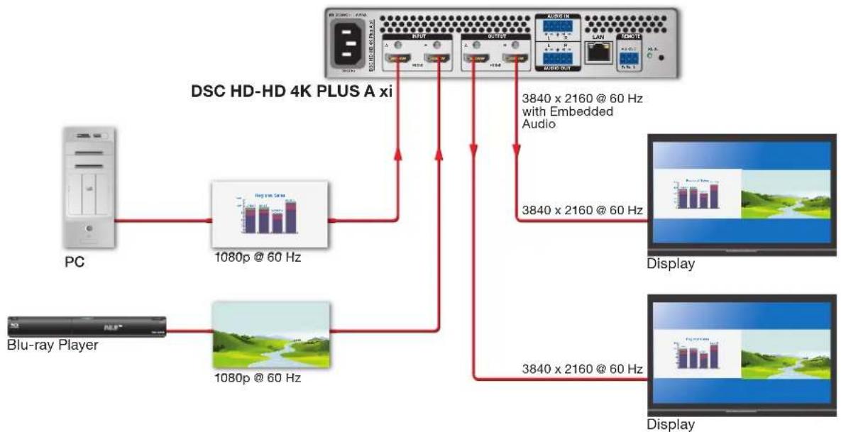
Two Inputs to Two Side-by-Side Outputs (xi Model Only)
Two HDMI inputs with the same resolution and refresh rate can be scaled and displayed as two side-by-side images on one or both of the outputs (see the example in figure 12). In this configuration, the aspect ratio selection (Fill or Follow) affects the appearance of the output as follows:
- Fill — The image fills the vertical space on its portion of the display (stretched to fit if necessary). This could result in a distorted image.
- Follow — The image is centered vertically on its portion of the display. If the image takes up less vertical space than is available for it on the display, black bars are added above and below the image to fill the space.
NOTE: The DSC HD-HD 4K PLUS A xi defaults to Input A if no video or incompatible video is connected to Input B (for example, if the resolution and refresh rate on Input A does not equal the resolution and rate on Input B).
flowchart
graph TD
    A["PC"] --> B["1080p @ 60 Hz"]
    C["Blu-ray Player"] --> D["1080p @ 60 Hz"]
    B --> E["DSC HD-HD 4K PLUS A xi"]
    D --> E
    E --> F["3840 x 2160 @ 60 Hz with Embedded Audio"]
    E --> G["3840 x 2160 @ 60 Hz"]
    F --> H["Display"]
    G --> I["Display"]
Figure 12. Two Inputs to Side-by-Side Display on One or Two Outputs
Securing the HDMI Connector Using the LockIt Cable Lacing Bracket
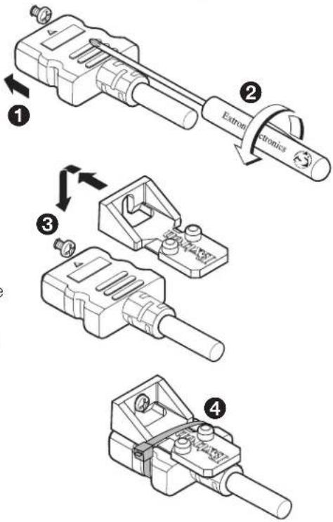
After connecting an input or output device to an HDMI connector, secure the connector in place with the provided LockIt bracket as follows:
-
Plug the HDMI cable into the panel connection (①).
-
Loosen the HDMI connection mounting screw from the panel enough to allow the LockIt lacing bracket to be placed over it (②).
-
Place the LockIt lacing bracket onto the screw and slide it up against the HDMI connector. Tighten the screw to secure the bracket (③).
-
Loosely place the included tie wrap around the HDMI connector and LockIt lacing bracket (④).
-
While holding the connector securely against the lacing bracket, tighten the tie wrap, then remove any excess length.
Connecting for Remote Control
The DSC HD-HD 4K A Series scalers have three control ports through which they can be connected to a computer or control system for configuration and control: the rear panel Remote RS-232 port (see Connecting to the RS-232 Port), the rear panel LAN port (see Ethernet LAN connector on page 9), and the front panel USB Config port (see Connecting to the USB Config Port on the next page).
Connecting to the RS-232 Port
The RS-232 port uses a protocol of 9600 baud, 8 data bits, 1 stop bit, no parity, and no flow control. To connect a computer or control system to the DSC Remote RS-232 port, use an Extron Universal Control cable (UC50' or UC100') or other female 9-pin-to-bare-wire RS-232 cable (see figure 13 on the next page).
- Wire the unterminated end of the RS-232 cable to the provided 3-pole captive screw connector as follows:
a. Connect the transmit wire to the left pin, which plugs into the Tx (transmit) port.
b. Connect the receive wire to the center pin, which plugs into the Rx (receive) port.
c. Connect the ground wire to the rightmost pin, which plugs into the ground port, marked with G.
-
Plug the captive screw connector into the RS-232 port on the rear panel.
-
Connect the 9-pin connector end of the RS-232 cable to the serial port of the computer or control system.
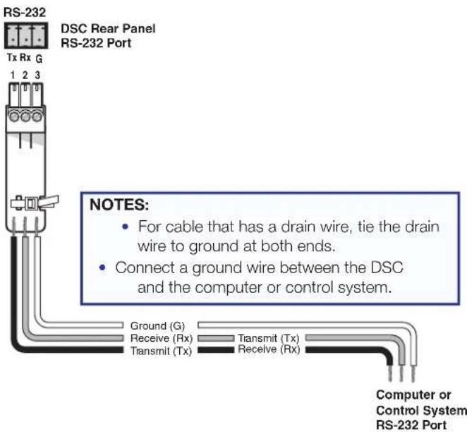
Figure 13. Connecting to the RS-232 Port
See SIS Commands on page 43 for information on sending SIS commands through this port.
Connecting to the USB Config Port
The USB mini-B USB Config port is located on the DSC front panel. It can be used to configure the DSC via the PCS software or SIS commands.
- Use a USB A-to-mini-B cable to connect the DSC USB Config port to a USB port on a computer.
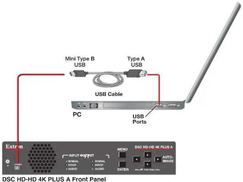
Figure 14. Connecting to the Front Panel USB Config Port
- When the DSC is first connected to a particular USB port on the computer, one of the following windows may open:
- Windows XP and earlier: If the following window opens, specify whether Windows Update will search the Web for the driver needed for the computer to communicate with the DSC via the USB port (this is not necessary if the USB driver already exists on the computer).
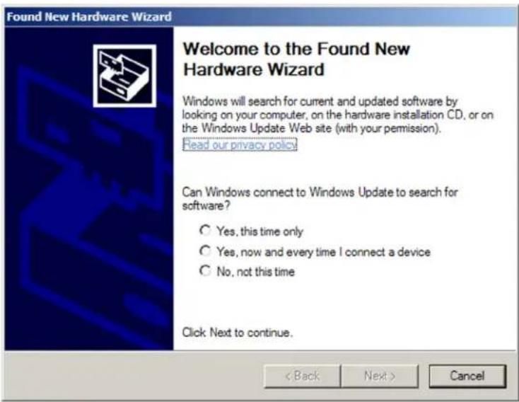
Figure 15. Found New Hardware Wizard Opening Screen
Select one of the following radio buttons:
- Select the Yes, this time only radio button for the computer to connect to Windows Update only this one time (recommended).
- Select the Yes, now and every time I connect a device radio button to automatically connect to Windows Update every time the DSC is connected to this USB port.
- Select the No, not this time radio button to not connect to Windows Update at this time (for example, if the driver is already installed).
NOTE: This wizard appears only the first time the DSC is connected to each USB port. It does not open again until you connect the DSC to a different USB port.
- Windows 7 and later: A pop-up notification appears on the Windows taskbar informing you that Windows Update is searching the Web for the USB driver and installing it. If desired, click the USB icon on the computer desktop to view the progress of the search. The Driver Software Installation window appears:
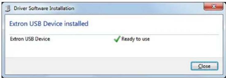
Figure 16. Driver Software Installation Window for USB Software
- (Windows XP and earlier) Click Next. On the next screen, if asked whether to install the driver automatically or from a specific location, select to install the software automatically.
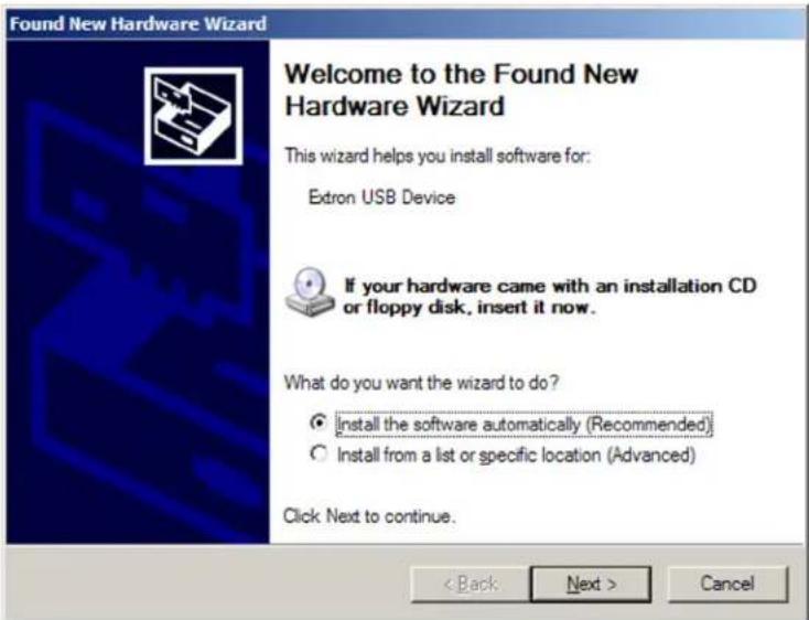
Figure 17. Selecting the Radio Button to Install the USB Driver Automatically
NOTE: If you have uploaded the PCS software to your computer, the USB driver is already installed and the screens do not appear.
The computer locates the driver needed for it to communicate with the DSC via the USB port.
- Windows XP or earlier: When the Completed window appears, click Finish to close the wizard.
Windows 7 or later: When the USB software has been located and downloaded, the message Ready to use appears on the Driver Software Installation screen (a pop-up message appears above the Windows taskbar if the screen is closed). Click Close to close the status window.
Operation
This section discusses the functions available through the front panel and the on-screen display (OSD) to configure and operate the DSC. Topics include:
- Front Panel Features
• On-screen Display Menu - Auto-Image
• Changing the Output Resolution and Refresh Rate
• Power Save Mode - Presets
- Locking the Front Panel (Executive Mode)
- Resetting
Front Panel Features
flowchart
graph LR
    A["Configuration"] --> B["Input"]
    B --> C["SIGNAL HDCP AUDIO"]
    C --> D["OUTPUT"]
    D --> E["SIGNAL HDCP AUDIO"]
    E --> F["MENU ENTER"]
    F --> G["DSC HD-HD 4K PLUS A xi HOLD FOR XGA/720p"]
    G --> H["AUTO-IMAGE"]
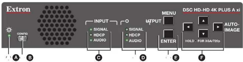
A Status LED (power and signal)
B USB Config port
© Input signal LEDs
Output signal LEDs
E Menu and Enter Buttons
F Navigation (arrow) Buttons
Figure 18. DSC HD-HD 4K PLUS A xi Front Panel
NOTE: Figure 18 shows the front panel of the xi model. The front panels of the non-xi models are identical except for the product name in the upper-right corner.
A Status LED (power and signal) — This bicolor LED lights steadily amber when the unit is powered on but no signal is present, blinks amber every 3 seconds when the unit is in standby mode, and lights steadily green when both power and an input video signal are present.
USB Config port — Connect a computer to this USB mini-B port for device configuration and firmware upgrades.
C Input signal LEDs — Light to indicate presence of an input signal and the type of audio signal if one is also present.
• Signal — Indicates that an input signal is present.
- HDCP — Indicates that the input signal is HDCP-encrypted content.
- Audio — Indicates that an embedded or analog audio signal is present on the input.
Output signal LEDs
- Signal — Indicates that HDMI video is being output. (If the video is muted, this LED does not light.)
- HDCP — Indicates that the output signal is HDCP-encrypted content.
- Audio — Indicates that an embedded or analog audio signal is present in the output signal.
Menu and Enter buttons — Let you access and make selections from the on-screen display menus (see Using the Front Panel Buttons with the OSD Menus on the next page for detailed explanations of these buttons and the arrow buttons).
F Navigation (arrow) buttons — (Left ◀, right ▶, up ▲, and down ▼ arrows) Let you navigate through the OSD submenus, lock the front panel controls (see page 41), perform Auto-Image (see page 38), and reset the output rate (see page 39).
On-screen Display Menu
The on-screen display menu enables you to configure and adjust the DSC from submenus displayed on a monitor or other display device connected to a rear panel output.
NOTE: The settings available through the OSD menu can also be selected via SIS commands (see the On-screen Menu Configuration commands on page 66).
Menu Overview
The OSD menu has seven configuration submenus and one read-only information screen. The OSD Menu Structure table on the next page shows the submenus and their items.
NOTE: The Device Info and Communication screens are read-only and give current device status.
The menu screen always displays the following items, regardless of which submenu is displayed.
- The Extron model name is in the upper-left corner.
• IP address and firmware version number are in the upper-right corner. - Current input resolution and refresh rate are in the lower-left corner.
• Current output resolution and refresh rate are in the lower-right corner.
| OSD Menu Structure | |||||||
| Submenu Sub | menu Items | ||||||
| Quick Setup | Input EDID | Output Rate HDCP | Authorized | Auto Memory | Aspect Ratio | Test Pattern | Output Audio Format |
| Picture Controls | Auto-Image | Image Position (H and V) | Image Size (H and V) | Brightness | Contrast Detail | ||
| Input | Film Detect | Active Video (H and V) | HDCP Authorized | Input EDID | Capture Display EDID | ||
| Output | Output Rate | Output A* Format---- Output B Format | HDCP Notification | Input AFL | Logo Logo | Position | |
| Audio | Audio Mute | Input Audio Format | Output Audio Format | Analog Gain | Volume | ||
| Advanced | Test Pattern | Screen Saver | Screen Saver Timeout | Aspect Ratio | Auto Memory | Overscan | Factory Reset |
| Communication | Serial Port | MAC Address | DHCP Mode | IP Address | Subnet Mask | Gateway | |
| Device Info (Read-only) | Unit Name Firmware Temperature | Input A*---- Input B Resolution, Pixel Clock, Total Lines, HDCP Status | Output A*---- Output B Resolution, Format, Display Info, HDCP Status | AFL | |||
*Only the xi model has two inputs and outputs (A and B). For the other two models, these screens show only Input or Output.
Using the Front Panel Buttons with the OSD Menu
Use the front panel Menu, arrow, and Enter buttons to access, navigate, and select items on the OSD menu.
- Menu — Press this button to activate or exit the OSD menu.
- Enter — Press this button to select submenus or submenu items, or to accept pending changes (moves a yellow outline to the first submenu item in the right panel). Press this button again to access the selections available from the outlined submenu.
- Navigation (arrow) buttons —
- Press the Up arrow (▲) and the Down arrow (▼) buttons to navigate through the submenus and submenu items.
The Down arrow button can also be used to reset the output rate (see Resetting the Output Rate on page 39) and, in conjunction with the Menu button, to lock the front panel (see Locking the Front Panel (Executive Mode) on page 41).
- Press the Right arrow (▶) button to access the selections available for the current submenu item.
When the OSD is closed, pressing this button performs an Auto-Image (see Auto-Image on page 38).
- Press the Left arrow (◀) button to exit a currently selected submenu or submenu item.
Using the OSD Menu
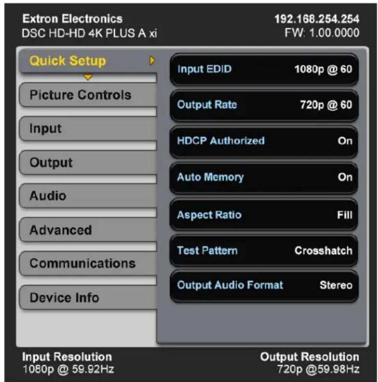
Figure 19. OSD Menu Initial View
To access and use the OSD menus:
- Press the Menu button once to open the OSD menu on the display. The menu system opens with the Quick Setup submenu displayed and the submenu name highlighted in yellow in the left panel (see figure 19).
- If you want to select a different submenu, press the front panel ▼ or ▲ button to move the highlighting to the desired menu.
- Press the Enter or ▶ button to access the menu items. A yellow outline appears around the first item.
- Press the ▼ or ▲ button to cycle through the items until the desired one is outlined.
- Press the Enter button to select the outlined item. The selected item is outlined in yellow. Yellow navigation arrows appear above, below, to the right, and to the left of the selected item field, indicating the front panel arrow buttons that you can press to move to the available selections.

Figure 20. Example of a Selected Submenu Item
NOTE: When you select a Picture Controls submenu item (for example, Brightness or Contrast), the OSD menu collapses so that the item is displayed alone on the screen to facilitate adjustment (see Adjusting the picture controls on page 24 to adjust settings on the Picture Controls submenu).
-
Press the arrow buttons to adjust the value as desired.
-
Press Enter to confirm your new values. Press it again if action confirmation is required.
-
Do any of the following:
- Press the ▲ or ▼ button to move to another item on the submenu and repeat steps 5 through 7.
- Press ◀ to exit the submenu. The yellow outline is removed from the item and returns to the submenu name. If desired, use the ▲ and ▼ buttons to select another submenu.
- Press Menu to exit the submenu and close the OSD menu.
NOTES:
- Settings in submenus that do not apply to the current input are shown as N/A.
- An asterisk following an item indicates that it is the default value.
- The OSD times out and closes after 1 minute if no buttons are pressed.
Quick Setup Submenu
This submenu provides access to common DSC settings.
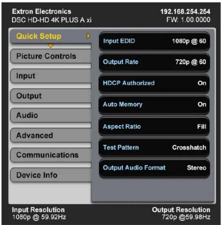
Figure 21. Quick Setup Submenu
From the Quick Setup submenu you can configure the following:
- Input EDID — Select this item to match the input EDID to the output rate or to set a discrete EDID (see the Input EDID Resolutions table on page 26 for EDID data). The default is Auto (match the current output resolution).
-
Output Rate — Select this item to set the scaler output resolution and refresh rate. The DSC HD-HD 4K A Series scalers have 80 factory installed output resolutions and rates and three custom user defined blocks for new resolutions (see the Output Resolutions and Refresh Rates Table on page 29). The default setting is 1080p @ 60 Hz.
-
HDCP Authorized — Select whether or not the scaler input will report to a source as an HDCP authorized device, thereby allowing HDCP-encrypted content. The default is On.
- Auto Memory — Select this item to enable or disable Auto Memories. When Auto Memories are enabled, the DSC automatically stores the current input configuration and picture control values as a preset in one of its 32 Auto Memory locations (see Auto Memories on page 40 for more information). The default is On.
- Aspect Ratio — Select this item to specify whether input signals will fill the entire output raster (Fill), or be automatically compensated to follow the native aspect ratio of the input signal (Follow). The default is Fill.
- Test Pattern — Select this item to choose a test pattern to aid in setting up the DSC and the corresponding display device. Available pattern selections are: Off (no test pattern), Crop, Alternating Pixels, Crosshatch, Color Bars, Grayscale, and Audio Test (displays a crop pattern and outputs 48 kHz, 24-bit pink noise). The default is Off.
- Output Audio Format — Select between stereo and dual mono. The default is Stereo.
Picture Controls Submenu
This submenu lets you adjust the image horizontal and vertical positions, image height and width, brightness, contrast, and sharpness (Detail) of the display.
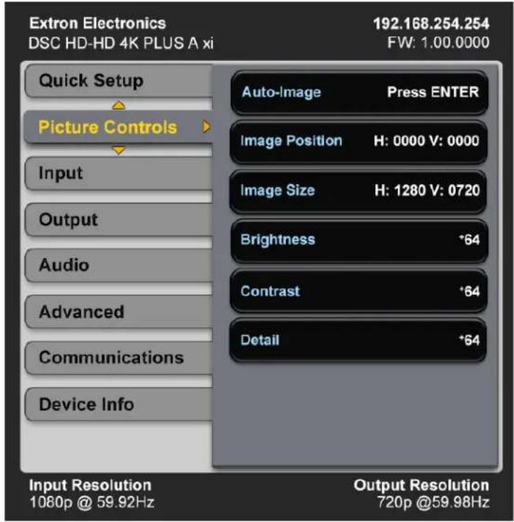
Figure 22. Picture Controls Submenu
The following picture settings can be adjusted:
- Auto-Image — Select this item, then press Enter to perform a one-time Auto-Image on the video input (see Auto-Image on page 38 for more information about this function).
- Image Position — Select this item to adjust the horizontal and vertical position of the image on the display. The ranges are:
• Horizontal position: -4096 through +4096 pixels
• Vertical position: -2160 through +2160 lines
- Image Size — Select this item to adjust the horizontal size (width) and vertical size (height) of the image. The ranges are:
• Horizontal size: 10 through 8192 of signal
• Vertical size: 10 through 4320 of signal
- Brightness — Select this item to adjust the black level of the video signal. The range is 0 through 127. The default is 64.
- Contrast — Select this item to adjust the range of white to black levels of the video signal. The range is 0 through 127. The default is 64.
- Detail — Select this item to adjust the image sharpness. The range is 0 to 127. The default is 64).
NOTE: An asterisk (*) before a value on a screen indicates that it is the default.
Adjusting the picture controls
When you select a Picture Controls submenu item, the OSD menu collapses so that the item is displayed alone on the screen to facilitate adjustment (see figure 23). The separate item field contains yellow arrows that indicate which front panel arrow buttons to press to adjust the item.
Image Position

H: 0000
V: 0000

Figure 23. Example of a Selected Picture Controls Submenu Item
After selecting the item to adjust, do the following:
- With the separate item field displayed, use the arrow buttons to select and adjust the desired settings as indicated by the yellow arrows on the screen. (To rapidly increment or decrement the values, press and hold the arrow button.)
Example: In figure 23, the yellow right and left arrows next to the H setting indicate that you can press the ◀ and ▶ buttons on the front panel to adjust the horizontal position. To adjust the vertical position, press the ▲ and ▼ buttons, as indicated by the yellow up and down arrows next to the V setting.
- When finished, press Enter to return to the OSD menu.
Input Submenu
This submenu allows you to perform certain input adjustments.
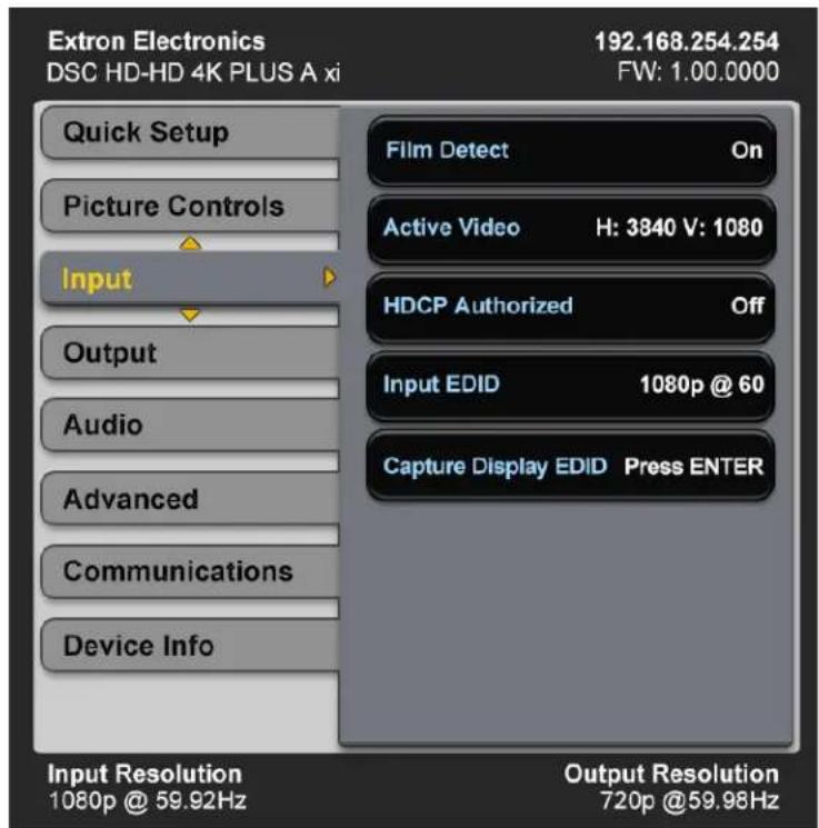
Figure 24. Input Submenu
From the Input submenu, you can configure the following:
- Film Detect — Select this item to enable and disable film detection, which helps maximize image detail and sharpness for video sources originating from film. After pressing Enter to select the item, press the ▲ or ▼ button to toggle between On (default) and Off.
If On is selected, the DSC detects and applies reverse pull-down for:
• 3:2 pull-down for 480i and 1080i @ 59.94 Hz
• 2:2 and 24:1 pull-down for 576i and 1080i @ 50 Hz
• Active Video — This view-only field shows the width in pixels (the H value) and the height in lines (the V value) of the applied input signal.
- HDCP Authorized — Select this item to enable or disable HDCP communication by selecting whether the DSC input will report to the source as an authorized HDCP sink. After pressing Enter to select this item, press the ▲ or ▼ button to toggle between On (default) and Off.
Setting HDCP authorization to 0ff is useful for devices that always encrypt their output if the downstream sink is capable of HDCP. If HDCP Authorized is disabled, most content from these sources can be passed as a non-encrypted signal. In a video system that should not transmit HDCP encrypted data, such as broadcast or streaming environments, HDCP authorization should be disabled at the input to ensure that the output remains unencrypted.
- Input EDID — Select this item to select an EDID (resolution and refresh rate) emulation for the HDMI inputs. You can match the input EDID to the output rate or set a discrete EDID. The Input EDID Resolutions table below lists the available EDID selections, including their SIS command variable numbers (see the Input EDID commands on page 54 for information on the SIS commands).
NOTE: On the xi model, the EDIDs on HDMI inputs A and B always match.
Input EDID Resolutions
| Resolution 23.98 | Hz 24 Hz 25 | Hz 29.97 | Hz 30 | Hz 50 Hz | 59.94 Hz | 60 Hz | ||
| Automatic* | * — Match current scaler output resolution | |||||||
| Output A HDMI | 1 (EDID export only) | |||||||
| Output B HDMI** | 2 (EDID export only) | |||||||
| 640x480 | 10 | |||||||
| 800x600 | 11 | |||||||
| 1024x768 | 12 | |||||||
| 1280x768 | 13 | |||||||
| 1280x800 | 14 | |||||||
| 1280x1024 | 15 | |||||||
| 1360x768 | 16 | |||||||
| 1366x768 | 17 | |||||||
| 1440x900 | 18 | |||||||
| 1400x1050 | 19 | |||||||
| 1600x900 | 20 | |||||||
| 1680x1050 | 21 | |||||||
| 1600x1200 | 22 | |||||||
| 1920x1200 | 23 | |||||||
| 480p | 24 25 | |||||||
| 576p | 26 | |||||||
| 720p | 29 30 31 32 33 34 | |||||||
| 1080i | 35 36 37 | |||||||
| 1080p | 38 39 | 40 41 | 42 43 | 44 45 | ||||
| 2K (2048x1080) | 46 47 | 48 49 | 50 51 | 52 53 | ||||
| 2048x1200 | 54 | |||||||
| 2048x1536 | 55 | |||||||
| 2560x1080 | 56 | |||||||
| 2560x1440 | 57 | |||||||
| 2560x1600 | 58 | |||||||
| 3840x2160 | 59 60 | 61 62 | 63 64 | 65 66 | ||||
| 3840x2160 Column** | 101 | 102 | 103 | 104 | 105 | 106 | 107 | 108 |
| 4096x2160 Column** | 111 | 112 | 113 | 114 | 115 | 116 | 117 | 118 |
| Custom EDID 1 | 201 | |||||||
| Custom EDID 2 | 202 | |||||||
| Custom EDID 3 | 203 | |||||||
*Default EDID
**xi model only
NOTE: EDID for 4096x2160 is not possible using native or preferred timings (VESA EDID Detailed Timings allow a maximum of 4095 active pixels). All factory EDIDs include a Video Identification Code (VIC) in the EDID CEA extension block, so that if a 4096x2160 EDID is desired, Extron recommends that the EDID be configured for 3840x2160 with the desired vertical refresh rate.
- Capture Display EDID — Select this item to capture the EDID of the sink attached to the output (output A on the xi model) and save it to one of the three custom EDID slots. The DSC assigns the captured EDID to its input (both inputs A and B on the xi model). To capture an EDID:
- Select Capture Display EDID, then press Enter. A list of the three custom EDID slots is displayed at the top of the OSD screen.
NOTE: If no EDID has been captured yet, the names displayed for the slots is the default: 1080p @ 60 Hz (EXT). The last three letters in parentheses represent the name of the display manufacturer (for example, EXT is an abbreviation of Extron).
C1: C1 3840x2160 @ 60 Hz (SAM)
C1: C1 1920x1080 @ 60 Hz (EXT)
C1: C1 1920x1080 @ 60 Hz (EXT)
Figure 25. Custom EDID Slots List Example
- Press the ▲ or ▼ button to highlight the slot to which you want to save the current display EDID.
- Press Enter. The display EDID is saved to the selected custom slot and assigned to the connected inputs.
Output Submenu
This submenu allows you to configure the HDMI outputs of the DSC.
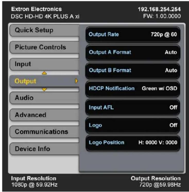
Figure 26. Output Submenu
- Output Rate — Select this item to specify the output resolution and refresh rate. The DSC HD-HD 4K A Series scalers have a range of resolutions from which to choose (see the Output Resolutions and Refresh Rates table on the next page for the available settings). The available rates depend on the selected resolution.
Three custom user-defined output rate slots are also available to be defined via SIS commands or via the Capture Display EDID item on the Input menu. If a custom EDID has not been captured from a display device or has not been uploaded to the unit, these slots default to 1080p @ 60 Hz.
When a resolution is applied to a user-defined EDID slot, its name is displayed in the Output Resolution panel in the format cn: nnnnxnnnn @ nn (XXX). An example would be C1: 1280x780 @ 60 Hz (EXT) (the last three letters in parentheses represent the name of the manufacturer of the device).
Output Resolutions and Refresh Rates
| Resolution 23.98 | Hz 24 Hz 25 | Hz 29.97 | Hz 30 | Hz 50 Hz 59.94 | Hz 60 Hz | ||
| 640x480 X | |||||||
| 800x600 X | |||||||
| 1024x768 X | |||||||
| 1280x768 X | |||||||
| 1280x800 X | |||||||
| 1280x1024 X | |||||||
| 1360x768 X | |||||||
| 1366x768 X | |||||||
| 1440x900 X | |||||||
| 1400x1050 X | |||||||
| 1600x900 X | |||||||
| 1680x1050 X | |||||||
| 1600x1200 X | |||||||
| 1920x1200 X | |||||||
| 480p XX | |||||||
| 576p X | |||||||
| 720p XXXXXX | |||||||
| 1080i | XXX | ||||||
| 1080p* | XX | XXXXXXXXX* | |||||
| 2048x1080 | XX | XXXXXXXXX | |||||
| 2048x1200 X | |||||||
| 2048x1536 X | |||||||
| 2560x1080 X | |||||||
| 2560x1440 X | |||||||
| 2560x1600 X | |||||||
| 3840x2160 | X | X | X | X | X | X*** | X*** |
| 4096x2160 | X | X | X | X | X | X*** | X*** |
| 3840x2160 column** | XX | XXXXXX | |||||
| 4096x2160 column** | XX | XXXXXX | |||||
| Custom output rate 1 | New resolution 1 | ||||||
| Custom output rate 2 | New resolution 2 | ||||||
| Custom output rate 3 | New resolution 3 | ||||||
*Default rate
**Supported on the xi model only
***Non-PLUS models: Available in YUV 4:2:0 Limited output format only
To select an output rate:
- Select Output Rate from the Output submenu and press the Enter button.
- Press the ▲ or ▼ button to select the resolution.
- Press the ▶ button to move the yellow selection arrows to the rate and press the ▲ or ▼ button to select a refresh rate.
- Press the Enter button to confirm your selections.
- Press ◀ to return to the Input submenu.
NOTE: If you do not confirm your resolution and rate selection within 15 seconds, the scaler returns to the previously selected resolution and rate.
- Output Format — This item lets you set the HDMI output format and control the output colorspace.
To select the format:
- Select Output Format from the Output submenu and press Enter.
- Press the ▲ or ▼ button to select the format.
- Press Enter to confirm your selection.
- Press ◀ to return to the Output submenu.
The format choices are:
• Auto (based on the EDID of the sink) (default)
• DVI RGB 444
• HDMI RGB 444 Full
• HDMI RGB 444 Ltd
• HDMI YUV 444 Ltd
• HDMI YUV 422 Ltd
• HDMI YUV 420 Ltd
- HDCP Notification — This item lets you select what is displayed on the HDMI output when the input signal contains HDCP-protected content and the output is a non-HDCP sink. After pressing Enter to select this item, press the ▲ or ▼ button to select between:
- Green w/OSD — Displays a green screen with the message HDCP Content on the HDMI output display (default).
- Black Screen — Displays a black screen and the output sync is maintained.
- User File — Displays a user-uploaded image. To upload images, use the PCS software Logo screen (see the DSC help file for the procedure).
- Input AFL — This item lets you enable and disable the Extron Accu-RATE Frame Lock (AFL). After pressing Enter to select this item, press the ▲ or ▼ button to toggle Input AFL on and off. The default is Off.
When 0n is selected, frame lock mode locks the output vertical refresh rate to the vertical refresh rate of the currently applied input using Accu-RATE Frame Lock technology. This ensures no frames of the input are repeated or dropped due to frame rate conversion. Input AFL mode can cause glitches or interruptions in the output sync when a new signal has been routed to the input as the DSC locks to the new vertical refresh rate.
NOTE: AFL locks the output refresh rate to the vertical rate of the input signal only if they are similar frequencies. If the input refresh rate greatly differs from the set output resolution, the DSC may not output a signal or may blink.
- Logo — Select this item to enable or disable display of a user-uploaded logo image. There are 16 slots available for storing logo files. To upload a logo file to the unit, use the Logo page of the PCS configuration program (see the DSC HD-HD 4K A Series help file for the procedure).
To select a logo to display:
- Select Logo from the Output menu and press Enter.
- Press the ▶ button to move the yellow selection arrows to the logo names list.
-
Press the ▲ or ▼ button to select a logo name. By default the logo slots are named ∅1 through 16. Use the Logo SIS commands (see the Logos commands beginning on page 61) or the Logo screen of the PCS software (see the DSC HD-HD 4K A Series help file) to change the logo name. The default is 0ff.
-
Press Enter to confirm your selection.
NOTE: To configure logo key effects (such as RGB keying, alpha keying, and so on) and to key logos over live video see the DSC HD-HD 4K A Series help file.
- Logo Position — This item lets you specify a position for the selected logo on the display. The default is H: 0000 V: 0000. To position the logo:
- Press the Enter button to select Logo Position from the Output submenu. The yellow selection arrows move to the H: parameter.
- Press the ▲ or ▼ arrow button to select the horizontal position.
- Press the ▶ button to move the yellow selection arrows to the V: parameter and press the ▲ or ▼ button to select the vertical position.
- Press the Enter button to confirm your selections.
- Press ◀ to return to the Output submenu.
Audio Submenu
This submenu allows you to configure the audio settings through the DSC.
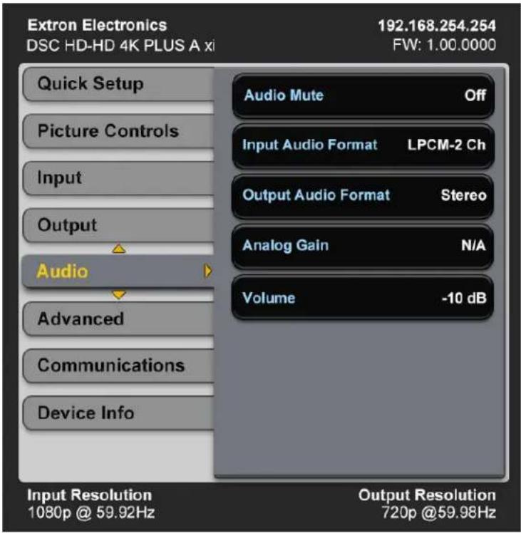
Figure 27. Audio Submenu
To use this submenu, press Enter to select this item, then press the ▲ or ▼ button to step through the selections.
- Audio Mute — Select this item to mute and unmute the output audio. You can make the following audio mute selections:
- Off — Audio output is not muted (default).
- Analog — Mutes the analog audio output only.
• Digital — Mutes the embedded digital audio output only. - On — Mutes both the analog and the embedded digital audio outputs.
- Input Audio Format — Select this item to choose the audio format for the input. The first item on the Audio menu shows the selected format of the audio.
| Audio Format Selection | Details |
| None | Configures input EDID with no audio support. All audio outputs are muted. |
| Analog Audio | Configures input EDID with no audio support. Analog audio from the 5-pole captive screw input is embedded into the HDMI output. |
| LPCM-2Ch | Configures input EDID for LPCM-2Ch support. Passes all digital audio input signals to the HDMI outputs. If LPCM-2Ch audio is present it is also de-embedded to the 5-pole captive screw analog output. |
| Multi-Ch | Configures input EDID for Multi-Ch support. Passes all digital audio input signals to the HDMI outputs. If LPCM-2Ch audio is present it is also de-embedded to the 5-pole captive screw analog output. |
| LPCM-2Ch Auto | Configures input EDID for LPCM-2Ch support. Passes all digital audio input signals to the HDMI outputs. If LPCM-2Ch audio is present it is also de-embedded to the analog 5-pole captive screw output.If no embedded audio is present on the input the DSC passes analog audio from the 5-pole captive screw input. |
| Multi-Ch Auto | Configures input EDID for Multi-Ch support. Passes all digital audio input signals to the HDMI outputs. If LPCM-2Ch audio is present it is also de-embedded to the analog 5-pole captive screw output.If no embedded audio is present on the input, the DSC passes analog audio from the 5-pole captive screw input. |
- Output Audio Format — Select this item to specify stereo or dual mono (Mono) for the analog and embedded digital audio output. Press Enter to select this item, then press the ▲ or ▼ button to toggle between the two formats. The default is Stereo.
- Analog Gain — Select this item to set the analog input gain value. Press Enter to select this item, then press the ▲ or ▼ button to increase or decrease the gain in 1 dB increments. The range is -18 dB through +24 dB. The default is 12 dB.
- Volume — Select this item to set the volume level in decibels for both the analog and embedded digital audio outputs. Press Enter to select the item, then press the ▲ or ▼ button to raise or lower the volume in increments of 1 dB. The range is -100 dB through 0 dB. The default is -10 dB.
Advanced Submenu
This submenu allows you to configure the global settings for the unit.
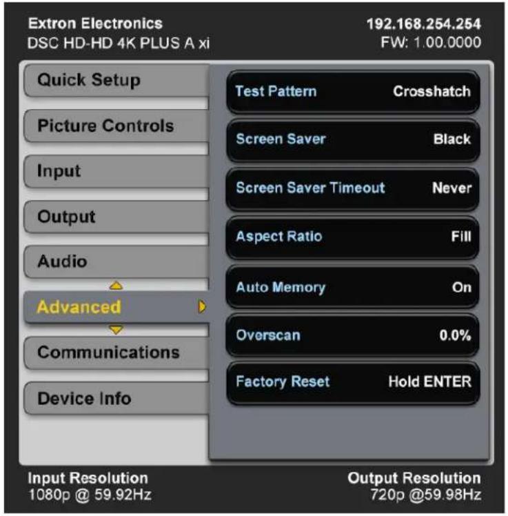
Figure 28. Advanced Submenu
The following items are available on the Advanced submenu:
- Test Pattern — Lets you choose a test pattern to use in setting up a display when outputting different resolutions. The default is Off.
The following test patterns are available:
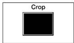
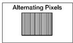
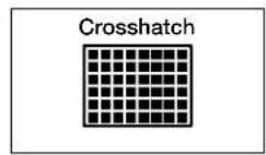
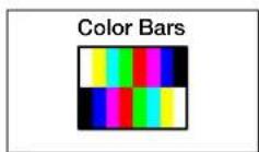
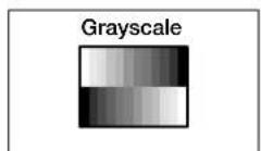
Figure 29. Test Pattern Items
NOTES:
- By default all test patterns include a single pixel wide crop pattern line.
- The Audio Test pattern displays a crop pattern and also outputs pink noise at 48 kHz, 24 bit.
- Test pattern selections persist through a power cycle.
- Screen Saver — Configures device behavior when no active input signal is detected. Options include a black (default) or blue screen, or a user provided logo file. Optionally, you can set a timeout to disable the HDMI output after a set duration to allow display devices (such as an LCD panel, plasma screen, or projector) to enter a lower power or standby state to increase panel or lamp life.
To select the screen saver:
-
Select Screen Saver from the Advanced menu and press Enter.
-
Press the ▲ or ▼ button to select the screen saver type. The menu selections are:
-
Black (default)
• Blue with a No Signal OSD message -
User Image — Displays an image that has been previously uploaded to the DSC. The location of this image on the screen can be adjusted using the OSD menu (see the Logo Position item of the Output submenu on page 31), SIS commands (see the Logo Horizontal Shift and Vertical Shift commands on page 62) or the PCS software (see the DSC HD-HD 4K A Series help file).
-
Press Enter to confirm your selection.
NOTE: The DSC exits screen saver mode when the front panel Menu or Enter button is pressed, a video test pattern is activated, or an active input is detected. If the unit is in front panel lock mode (see Locking the Front Panel (Executive Mode) on page 41), pressing a front panel button exits time out but access to any front panel controls or the menu system is disabled.
- Screen Saver Timeout — Lets you specify a number of seconds the selected screen saver is displayed before the output sync times out.
To set the sync timeout:
- Select Screen Saver Timeout from the Advanced menu and press Enter.
- Press the ▲ or ▼ button to select the amount of time before output sync times out. You can select a duration of 0 (timeout is immediate) to 500 seconds before the output sync times out. The default is Never, meaning that the sync does not time out.
- Aspect Ratio — Sets the aspect ratio to Fill (fills the entire output raster) or Follow (follows the native aspect ratio of the input).
- In fill mode, if you want to set an aspect ratio adjustment for a single input rate, you can select the correct image size and position manually from the Picture Controls submenu (Image Size and Position) (see Picture Controls Submenu on page 23).
- In follow mode, each input rate is displayed with its native aspect ratio (4:3, 5:4, 16:9, or 16:10) with the correct letter box or pillar box settings, visible under the Image Size and Image Position items on the Picture Controls submenu. If you want a single input to fill the screen in follow mode, you can manually set the Image Position item on the Picture Controls submenu to 0,0 and set the Image Size to match the current output rate X, Y.
- Auto Memory — Enables or disables Auto Memory. When Auto Memory is set to On (default), the DSC stores the current input configuration and picture control values as an input preset (see Auto Memories on page 40 for more information).
- Overscan — Lets you select a default overscan mode to apply to SMPTE input rates (480i, 576i, 480p, 576p, 720p, 1080i, 1080p, 2K, and 4K). This zooms and crops SMPTE inputs to mask edge effects and ancillary data that may occur in broadcast signals. The selections are 0% (default), 2.5%, and 5%.
NOTE: If the overscan mode is not 0%, when Auto-Image is performed on an SMPTE input rate, it refers to the default input values for sizing and centering instead of performing a true Auto-Image.
- Factory Reset — Resets the unit to its factory default values (removing any user-specified values) while retaining all TCP/IP settings.
To reset using the OSD menu, press and hold the Enter button until Factory Reset is displayed (approximately 5 seconds). The message remains for approximately 1 minute after the reset is complete to allow time for the display device to sync with the DSC output.
NOTE: The equivalent SIS command is Esc ZXXX ←.
For other reset methods, see Resetting on page 42.
Communications Submenu
This menu enables you to view the RS-232 remote port baud rate, port type, and the unit MAC address, and to edit the IP settings.
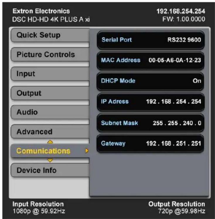
Figure 30. Communications Screen
The Communications submenu contains the following items (see figure 30 on the previous page):
- Serial Port — (View only) Displays the port type (RS-232) and the baud rate. The protocols for this port is 9600 baud, eight data bits, no stop bits, and no parity.
- MAC Address — (View only) Displays the media access code (hardware address) of the unit. This address is hard-coded at the factory and cannot be changed.
- DHCP Mode — When this mode is enabled (On), the unit configures its IP address and other network settings from the DHCP server. The default is Off.
To enable or disable DHCP mode:
- Select DHCP Mode from the Communications submenu and press Enter.
- Press the ▲ or ▼ button to select On or Off and press Enter again.
You can also set the DHCP mode via SIS commands (see the DHCP mode commands on page 68), the PCS software, or the DSC HD-HD 4K A Series internal web page.
- IP Address — Lets you set the IP address for the unit. The default address is 192.168.254.254.
- Subnet Mask — Lets you set the subnet mask for the unit. The default subnet mask is 255.255.0.0.
- Gateway — Lets you set the gateway address for the unit. The default gateway address is 0.0.0.0.
Setting the IP, subnet mask, and gateway addresses
To set the IP address, subnet mask, or gateway address:
- Select the item to be changed from the Communications submenu and press Enter.
- Press the ◀ and ▶ buttons to move the yellow selection arrows and highlighting to the octet to be changed and press Enter.
- Press the ▲ or ▼ button to select the desired value for the octet, then press Enter.
- To rapidly increase or decrease the octet value, press and hold the ▲ or ▼ button until the desired value is displayed.
- Repeat step 2 for the next octet to be changed, or press Enter again to return to the submenu level.
Device Info Screen
This read-only screen provides a quick view of certain selections, parameters, and status information for the DSC.
NOTE: The following example shows a DSC HD-HD 4K PLUS A xi Device Info screen, which shows two inputs (Input A and Input B) and two outputs (Output A and Output B). The non-xi models include only a single Input and Output.
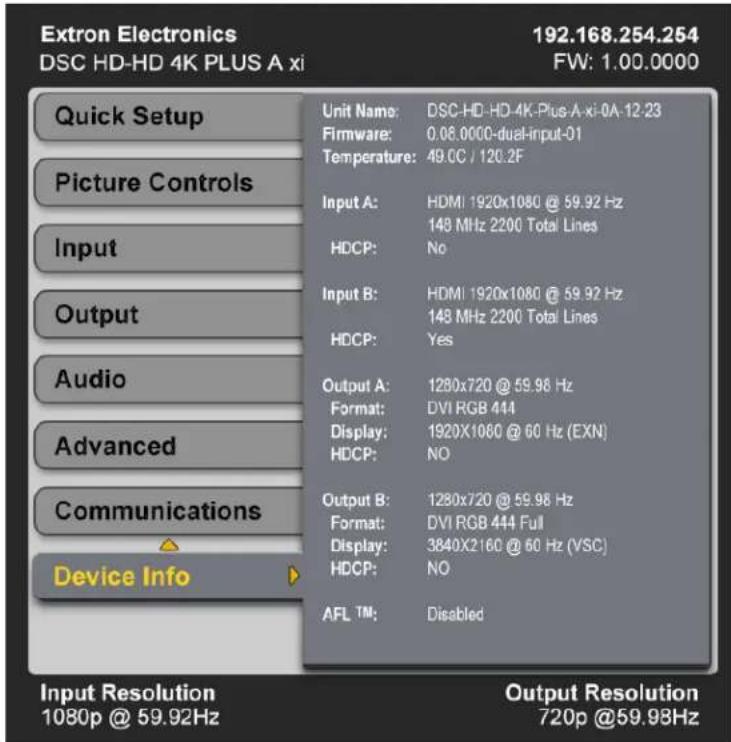
Figure 31. Device Info Screen, xi Model Example
Auto-Image
When Auto-Image is performed, the DSC attempts to size and position the image to fill the display screen (fill mode) or use the native aspect ratio of the input (follow mode). Only the horizontal and vertical image positioning and the horizontal and vertical image size are adjusted by the Auto-Image. All other controls are left unchanged.
- If the aspect ratio has been set to Fill, the horizontal and vertical image position returns to , and the horizontal and vertical image size is set to match the current output rate.
- If the aspect ratio has been set to Follow, the horizontal and vertical image position and size are set to maintain the native aspect ratio of the input rate with respect to the current output resolution.
Auto-Image is useful in applications in which a variety of new input sources may be encountered (such as when a matrix switcher is connected). It is also useful for centering and sizing an image that has been adjusted out of default settings.
You can perform a one-time Auto-Image by the following methods:
- Front panel button — While the OSD is not displayed, press the Auto-Image (▶) button twice. The first press displays the message Press Auto again to Confirm on the OSD. The second press initiates the Auto-Image.
- OSD submenu — Select Auto-Image from the Picture Controls submenu (see page 23).
• SIS commands (see the Auto-Image commands on page 54).
• PCS software (see the DSC HD-HD 4K A Series help file).
Changing the Output Resolution and Refresh Rate
In addition to the Output submenu (see page 28), other methods for setting the output resolution and refresh rate include resetting the output rate using the front panel ▼ button (see Resetting the Output Rate on page 39, SIS commands (see the Output Configuration commands beginning on page 59), and the PCS software program (see the DSC HD-HD 4K A Series help file).
Custom Rates
In addition to the 80 factory output resolutions, three custom user-defined rates are available. Using SIS commands, the Capture Display EDID item on the Input submenu, or the PCS software program, you can capture the EDID of the device connected to the HDMI output or upload a custom EDID file from a computer (see the Output Scaler Rate commands on page 59 or the PCS software DSC HD-HD 4K A Series help file). When no custom EDIDs are defined, these three custom slots default to 1080p @ 60 Hz.
The OSD dynamically updates based on the current file stored in the custom EDID slot. For example, if a custom 720p EDID has been uploaded, the OSD would display C1: 1280x720 @ 60 Hz. See the Output Rate item of the Output submenu on page 28 for more information.
When you set this resolution using the menu system, a confirmation prompt appears. If you do not respond to the prompt by pressing Enter within 20 seconds, the DSC reverts to the previous resolution.
Resetting the Output Rate
If an output image cannot be displayed due to an incompatible output rate, you can use the front panel down arrow ▼ button to toggle the output rate between 1024x768 @ 60 Hz (XGA) and 1280x720 (720p) @ 60 Hz. To set the rate or toggle between the two rates:
- Ensure that the OSD is closed by pressing and holding Menu for 3 seconds.
- Press and hold the ▼ button until a message appears on the display indicating the new rate (approximately 5 seconds).
NOTE: On the front panel, the ▼ button is labeled Hold ▼ for XGA/720p.
Power Save Mode
In power save (standby) mode, all non-essential hardware is shut down in order to conserve power. The default state for power save mode is Off.
- To enable power save mode, enter the Power Save ON SIS command (see the Power Save Mode commands on page 60). While the DSC is in power save mode, the Status LED (power and signal) blinks amber slowly.
- To exit power save mode, do one of the following:
• Enter the Power Save OFF SIS command.
- Press any front panel button (if the front panel is locked, this method does not work).
• Cycle power to the unit.
NOTE: Many functions in the PCS software, such as backup and restore, are not accessible while the unit is in power save mode.
Presets
A preset is a set of input parameters that are either saved by you or automatically by the DSC as a file in DSC memory. Saved presets can be recalled and their settings implemented at any time. A preset saves time by enabling you to apply a group of settings to the DSC at one time. The DSC HD-HD 4K A Series scalers have two types of presets: Auto Memories and input presets.
Auto Memories
The DSC has 32 memory locations in which the current input configuration and picture control values are automatically stored as a preset, when Auto Memory is enabled. An Auto Memory preset is recalled when an identical input resolution and rate is applied to the input.
Auto memories can be enabled using the OSD (see the Auto Memory item on the Advanced submenu on page 35), by SIS commands (see the Auto Memories commands on page 58), and the PCS software (see the DSC HD-HD 4K A Series help file).
The following information is stored in an Auto Memory preset:
- Contrast • Horizontal image position
- Brightness • Vertical image position
• Detail • Horizontal image size (width)
• Active pixels (H Active) • Vertical image size (height)
• Active lines (V Active)
Input Presets
The DSC HD-HD 4K A Series scalers have 128 memory slots in which you can save input presets. These presets allow a matrix switcher with multiple types of video inputs (such as an XTP) to be placed upstream from the DSC to expand the number of video sources. Input presets can be saved and recalled only through SIS commands (see the Input Presets commands on page 59).
- When you recall an input preset, it fills the output raster based on the sizing and positioning that it had at the time it was saved.
- Input presets can be saved based on one input rate and recalled to a different rate. This enables presets to be used as aspect ratio or other quick-sizing shortcuts.
Values for the following settings are saved in input presets:
- Contrast • Active lines (V Active)
- Brightness • Horizontal image position
• Detail • Vertical image position - Film detect
- Horizontal image size (width)
- Audio gain and attenuation
- Vertical image size (height)
• Active pixels (H Active) • Preset name
Saving a preset when using a matrix switcher
When using the DSC with a matrix switcher, do the following to save a preset:
- Switch each input of the matrix to the DSC.
- Configure each input: size, position, detail, brightness, and contrast. The remaining settings (active pixels and lines) are not user-configurable, but are stored automatically as part of the preset.
- Save the settings to a preset for recall by the control system when that matrix input is routed to the HDMI input.
Locking the Front Panel (Executive Mode)
To prevent access by unauthorized users or accidental changes to the DSC settings, you can lock the front panel controls by placing the DSC in executive mode. In this mode, all front panel buttons are disabled and control is available only by SIS commands.
To lock the front panel, do any of the following:
- Press and hold the front panel Menu and ▼ buttons until the OSD displays the message Executive Mode Enabled (approximately 5 seconds). The message remains on the OSD approximately 2 seconds.
- Enter the Enable SIS command (see the Front Panel Lock (Executive Mode) commands on page 65).
- Select Lock Front Panel on the General Settings screen of the PCS software (see the DSC HD-HD 4K A Series help file).
To unlock the front panel, do any of the following:
- Press and hold the front panel Menu and ▼ buttons again until the OSD displays the message Executive Mode Disabled (approximately 5 seconds). The message remains on the OSD approximately 2 seconds.
- Enter the Disable SIS command (see the Front Panel Lock (Executive Mode) commands).
- Select Unlock Front Panel on the PCS software General Settings screen (see the DSC HD-HD 4K A Series help file).
Resetting
Resetting the unit causes various settings to revert to the defaults that were set at the factory. Resets can be performed via the front panel buttons, the rear panel Reset button, the OSD, the PCS software, or SIS commands. The following resets are available:
- Factory defaults — This reset clears all user-specified settings but retains the TCP/IP settings. You can perform this reset by:
- Selecting Factory Reset from the Advanced submenu of the OSD (see the Factory Reset item on the Advanced submenu on page 36)
- Entering the SIS command to reset all device settings to factory default (see the Resets commands on page 66)
- Selecting Reset Device from the Device tab menu in the PCS software When the reset is complete, the message Factory Reset is displayed on the OSD.
- Resetting using the Reset button — The Reset Modes Summary table summarizes the reset modes that are accessible via the recessed Reset button on the rear panel.
| Reset Modes Summary | |||
| Mode A | Activation Result Purpose and Notes | ||
| 1 Hold in the rear panel Reset button while applying power to the unit. | Restores the factory-installed default firmware version for a single power cycle.Retains all user files and settings, including audio adjustments, and IP settings. | Use mode 1 to remove a version of firmware for one power cycle if incompatibility issues arise. | |
| 4 Hold in the Reset button until the Reset LED blinks twice (once after approximately 3 seconds and again after 6 seconds). Then, within 1 second, press Reset momentarily (for less than 1 second). | Sets the following to factory defaults:IP address — 192.168.254.254Subnet mask — 255.255.0.0Gateway address — 0.0.0.0DHCP — 0ffSets port mapping to the factory default.The Reset LED blinks four times in quick succession during the reset. | Mode 4 sets all IP information to factory defaults.It does not replace any user-installed firmware.This is equivalent to the SIS command 1ZQQQ. | |
| 5 Hold in the Reset button until the Reset LED blinks three times (once after approximately 3 seconds, again after 6 seconds, and then again after 9 seconds). Then, within 1 second, press Reset momentarily (for less than 1 second). | Performs a complete reset to factory defaults except the firmware.Does everything that mode 4 does Presets all user-modifiable configuration to default values, including IP settings and real-time adjustments.Deletes all user-loaded files, including user images.The Reset LED blinks four times in quick succession during the reset. | Mode 5 is useful if you want to start over with the default configuration.This is equivalent to the SIS command ZQQQ. | |
| NOTE: Mode 5 reset clears all adjustments. To save these settings, use the PCS software program and select Backup from the DSC HD-HD 4K PLUS A tab menu before you perform this reset (see the control DSC HD-HD 4K A Series help file for more information). | |||
Remote Configuration and Control
This section describes the methods by which the DSC HD-HD 4K A Series can be configured and controlled remotely: the Extron Simple Instruction Set (SIS) commands, the web page, and the PCS software. It describes the available SIS commands and the controls on the web page and also provides instructions for obtaining and accessing the PCS software. Topics include:
• SIS Commands
• Command and Response Table for SIS Commands
• Product Configuration Software (PCS) Program
• DSC HD-HD 4K A Series Web Page
SIS Commands
You can use SIS commands to configure and control the DSC via a host computer or other device (such as a control system) attached to the rear panel RS-232 connector, the front panel USB port or the rear panel LAN port. Enter commands using an application such as the Extron DataViewer, available at www.extron.com (see the DataViewer Help file to use this program). The RS-232 port uses a protocol of 9600 baud, 8 data bits, 1 stop bit, no parity, and no flow control.
SIS commands consist of one or more characters per field. No special characters are required to begin or end a command sequence. When the DSC determines that a command is valid, it executes the command and sends a response to the host device. All responses from the scaler to the host end with a carriage return and a line feed (CR/LF = ←), indicating the end of the response character string (one or more characters).
Copyright Information
The DSC sends the following copyright message if power is cycled while the DSC is connected to the host. It displays on the computer screen only with an RS-232 connection.
(c) Copyright 20nn, Extron Electronics, DSC HD-HD 4K [PLUS] A [xi], Vn.nn, 60-1573-0n
WWW, DD Mmm YYYY hh:mm:ss
(Where 20nn is the year, Vn.nn is the firmware version, 60-1573-0n is the model number, and Www is the day of the week.)
DSC-initiated Messages
When a local event such as a front panel selection or adjustment takes place, the DSC responds by sending a message to the host. No response is required from the host. Examples of DSC-initiated messages are listed below.
- Reconfig The DSC sends this response when a change in the input frequency is detected.
- Hplg0 X2 * X69 ← The DSC sends this response when hot plug event X69 is detected on output X2, for example, when an HDMI output is unplugged and reconnected. X2 = Output. For X2: 1 = HDMI A 2 = HDMI B (xi model only) X69 = Hot plug change. For X69: 1 = New sink connected 2 = Sink disconnected
- In∅∅ • X61 ← (Non-xi models) The DSC sends this response when a change in input signal presence occurs. X61 = Video signal status. For X61: ∅ = video signal not detected 1 = video signal detected
- In00 • X61 * X61 ← (xi model) The DSC sends this response when a change in input signal presence occurs on input A or B. X61 = Video signal status (INA * INB). For X61: ∅ = video signal not detected 1 = video signal detected
- HdcpI [X1] * [X44] ← The DSC sends this response when a change in HDCP status of input [X1] occurs. [X44] = HDCP status. For [X44]: ∅ = No source detected 1 = Source detected but no HDCP is present 2 = Source detected with HDCP
- Hdcp0 X2 * X44 ← The DSC sends this response when a change in HDCP status of output X2 occurs. X44 = HDCP status. For X44: ∅ = No sink detected 1 = Sink detected but no HDCP is present 2 = Sink detected with HDCP
- Psav9 ← The DSC sends this response when it enters power save mode due to the unit exceeding its maximum operating temperature.
Error Responses
When the DSC receives a valid command, it executes the command and sends a response to the host device. If the unit is unable to execute the command because the command contains invalid parameters, it returns an error response to the host.
E01 — Invalid input number
E10 — Invalid command
E11 — Invalid preset number
E12 — Invalid port number
E13 — Invalid parameter
E14 — Invalid command for this configuration
E17 — Invalid command for signal type
E22 — Busy
E24 — Privilege violation
E28 — Bad file name or file not found
E33 — Bad file type or size
Using the Command and Response Table
The Command and Response Table for SIS Commands, beginning on page 54, lists the commands that the DSC scaler recognizes as valid, the responses that are returned to the host, a description of the command function or the results of executing the command, and some examples of the command syntax in ASCII.
NOTE: Unless otherwise stated, upper- and lowercase text can be used interchangeably in the commands.
| ASCII to HEX Conversion Table | Esc 1B | CR ∅D | LF ∅A | |||||||
| Space 20 | ! | 21 | " | 22 | # | 23 | $ 24 | % 25 | & 26 | ' 27 |
| ( 28 | ) | 29 | * | 2A | + | 2B | , 2C | . 2D | . 2E | / 2F |
| ∅ 30 | 1 | 31 | 2 | 32 | 3 | 33 | 4 34 | 5 35 | 6 36 | 7 37 |
| 8 38 | 9 | 39 | : | 3A | ; | 3B | < 3C | = 3D | > 3E | ? 3F |
| @ 40 | A | 41 | B | 42 | C | 43 | D 44 | E 45 | F 46 | G 47 |
| H 48 | | | 49 | J | 4A | K | 4B | L 4C | M 4D | N 4E | O 4F |
| P 50 | Q | 51 | R | 52 | S | 53 | T 54 | U 55 | V 56 | W 57 |
| X 58 | Y | 59 | Z | 5A | [ | 5B | \ 5C] | 5D | ^ 5E | _ 5F |
| ` 60 | a | 61 | b | 62 | c | 63 | d 64 | e 65 | f 66 | g 67 |
| h 68 | i | 69 | j | 6A | k | 6B | l 6C | m 6D | n 6E | o 6F |
| p 70 | q | 71 | r | 72 | s | 73 | t 74 | u 75 | v 76 | w 77 |
| x 78 | y | 79 | z | 7A | { | 7B | l 7C} | 7D | ~ 7E | DEL 7F |
Figure 32. ASCII to Hexadecimal Character Conversion Table
Symbol Definitions
- = Space
← = Carriage return with line feed
← or | = Carriage return with no line feed
Esc or W = Escape
^24 = Superscripts indicate the error message displayed if the command is entered incorrectly or with invalid parameters (see Error Responses on the previous page).
NOTE: If the unit does not support or recognize an entered command, it does not respond to the command in any way.
x1 = Input selection
1 = HDMI (HDMI A on the xi model)
2 = HDMI B (xi model only)
X2 = Output
1 = HDMI (HDMI A on the xi model)
2 = HDMI B (xi model only)
X3 = Input video format
∅ = No input signal detected
1 = HDMI
2 = DVI
x6 = Total lines
X7 = Total pixels
Response is four digits, padded with zeros.
x8 = Active pixels
Response is four digits, padded with zeros.
X9 = Active lines
Response is four digits, padded with zeros.
x10 = On or off (enable or disable)
∅ = Off or disable
1 = On or enable
X12 = Internal temperature in degrees Celsius
Response is two digits.
X13 = Horizontal and vertical frequencies
Response format is three digits with leading zeros and one decimal place (example: 175.3).
X14 = Text label, preset name, or logo name (up to 32 characters)
NOTES:
- Input presets saved without a name are given the default name Input Preset nnn (for example, Input Preset 005).
- Logos saved without a name are given the default name Logo nn (for example, Logo 05).
X15 = Picture adjustments - ∅ to 127. Default is 64.
Response is three digits, padded with zeros.
X16 = Horizontal and vertical image position:
Horizontal = -4096 to +4096
Vertical = -2400 to +2400
Response is four digits with leading + or - and padded with zeros (example: -∅175).
X17 = Horizontal and vertical image size (depends on resolution)
Response is four digits, padded with zeros (example: ∅175).
X20 = EDID emulation
Response is three digits padded with zeros.
∅ = Automatic — Matches the current scaler output resolution (default)
| Resolution 23.98 Hz | 24 Hz 25 Hz | 29.97 Hz | 30 Hz | 50 Hz 59.94 Hz | 60 Hz | ||
| Automatic* | ^* — Match current scaler output resolution (EDID only) | ||||||
| Output A HDMI | 1 (EDID export only) | ||||||
| Output B HDMI** | 2 (EDID export only)** | ||||||
| 640x480 | 10 | ||||||
| 800x600 | 11 | ||||||
| 1024x768 | 12 | ||||||
| 1280x768 | 13 | ||||||
| 1280x800 | 14 | ||||||
| 1280x1024 | 15 | ||||||
| 1360x768 | 16 | ||||||
| 1366x768 | 17 | ||||||
| 1440x900 | 18 | ||||||
| 1400x1050 | 19 | ||||||
| 1600x900 | 20 | ||||||
| 1680x1050 | 21 | ||||||
| 1600x1200 | 22 | ||||||
| 1920x1200 | 23 | ||||||
| 480p | 24 25 | ||||||
| 576p | 26 | ||||||
| 720p | 29 30 31 32 33 34 | ||||||
| 1080i | 35 36 37 | ||||||
| 1080p | 38 39 | 40 41 | 42 43 | 44 45 | |||
| 2048x1080 | 46 47 | 48 49 | 50 51 | 52 53 | |||
| 2048x1200 | 54 | ||||||
| 2048x1536 | 55 | ||||||
| 2560x1080 | 56 | ||||||
| 2560x1440 | 57 | ||||||
| 2560x1600 | 58 | ||||||
| 3840x2160 | 59 60 | 61 62 | 63 64** | 65*** | 66*** | ||
| 3840x2160 Column** | 101 | 102 | 103 | 104 | 105 | 106 | 107 |
| 4096x2160 Column** | 111 | 112 | 113 | 114 | 115 | 116 | 117 |
| Custom EDID 1 | 201 | ||||||
| Custom EDID 2 | 202 | ||||||
| Custom EDID 3 | 203 | ||||||
*Default EDID
**xi model only
NOTE: EDID for 4096 x 2160 is not possible using native or preferred timings (VESA EDID detailed timings allow a maximum of 4095 active pixels). All factory EDIDs include a VIC (Video Identification Code) in the EDID CEA extension block, so if 4096 x 2160 EDID is desired, it is recommended that EDID is configured for 3840 x 2160 at the desired vertical refresh rate.
X21 = Output scaler resolution
Response is three digits, padded with a zero.)
| Output Resolutions and Refresh Rates (X21 = 10 through 203) | |||||||||
| Resolution 23.98 | Hz 24 Hz 25 | Hz 29. | 97 Hz 30 | Hz 50 Hz 59.94 Hz | 60 Hz | ||||
| 640x480 | 10 | ||||||||
| 800x600 | 11 | ||||||||
| 1024x768 | 12 | ||||||||
| 1280x768 | 13 | ||||||||
| 1280x800 | 14 | ||||||||
| 1280x1024 | 15 | ||||||||
| 1360x768 | 16 | ||||||||
| 1366x768 | 17 | ||||||||
| 1440x900 | 18 | ||||||||
| 1400x1050 | 19 | ||||||||
| 1600x900 | 20 | ||||||||
| 1680x1050 | 21 | ||||||||
| 1600x1200 | 22 | ||||||||
| 1920x1200 | 23 | ||||||||
| 480p | 24 25 | ||||||||
| 576p | 26 | ||||||||
| 720p | 29 63 31 32 33 34 | ||||||||
| 1080i | 35 36 37 | ||||||||
| 1080p* | 38 39 | 40 41 | 42 43 | 44 45* | |||||
| 2048x1080 | 46 47 | 48 49 | 50 51 | 52 53 | |||||
| 2048x1200 | 54 | ||||||||
| 2048x1536 | 55 | ||||||||
| 2560x1080 | 56 | ||||||||
| 2560x1440 | 57 | ||||||||
| 2560x1600 | 58 | ||||||||
| 3840x2160 | 59 60 | 61 62 | 63 64*** | 65*** | 66*** | ||||
| 4096x2160 | 69 70 | 71 72 | 73 74*** | 75*** | 76*** | ||||
| 3840x2160 Column** | 101 | 102 | 103 | 104 | 105 | 106 | 107 | 108 | |
| 4096x2160 Column** | 111 | 112 | 113 | 114 | 115 | 116 | 117 | 118 | |
| Custom rate 1 | 201 | ||||||||
| Custom rate 2 | 202 | ||||||||
| Custom rate 3 | 203 | ||||||||
*Default output resolution
**xi model only
***Non-PLUS model: Available only at YUV 4:2:0 Limited output formats

= Supports buffered output mode (xi model only)

= Supports left-right column mode only on outputs A and B respectively (xi model only)
NOTE: Custom output rates are supported only as buffered outputs and not column outputs (xi model).
X22 = Test patterns
∅ = Off (default)
1 = Crop
2 = Alternating pixels
3 = Crosshatch
4 = Color bars
5 = Grayscale, 32-level split
6 = Audio Test (Crop pattern, OSD text Audio Test. Outputs pink noise at 48 kHz, 24 bits, channels 1 and 2.)
X23 = Input video mode
∅ = Single channel mode (default)
1 = Left-right column mode (Input is paired with the adjacent input connector: A or B.)
X26 = Input presets - 1 to 128
Response is three digits padded with zeros.
X28 = Output sync timeout — 1 to 500 seconds in 1-second increments
∅ = The output sync is instantly disabled with no active input.
501 = The output sync never times out (default).
Response is three digits padded with zeros.
X29 = Front panel lock (executive mode)
∅ = Disable lock mode (front panel controls are available) (default).
1 = Enable lock mode (front panel controls are locked).
X30 = OSD menu status
∅ = Off (default)
1 = On (displayed)
X31 = Verbose mode
∅ = None (default for LAN connection)
1 = Verbose mode (default for RS-232 and USB connection)
2 = Tagged response for queries
3 = Verbose mode and tagged response for queries
NOTES:
- In verbose response mode, the DSC responds with unsolicited responses for value and setting changes that may result from a signal change, or a setting adjustment made via another interface.
For example, the DSC can send out a notice of a change in some setting without receiving a query via a PC or a control system. That change could have been a result of an internal process, a selection made from the front panel, or a selection made from the OSD. This is an example of a verbose (wordy) relationship between the controller and a connected device.
- If tagged responses are enabled, all "view" commands return the command string plus the data, the same as in responses for setting a value. For example:
Command: Esc M SSAV ←
Response: SsavM X11 ← (tagged response)
or x11 ← (untagged response)
X32 = Unit name (TCP/IP Hostname — A text string of up to 63 characters. A - Z, ∅ - 9, and the hyphen (-) are permitted.
The first character must be a letter.
The last character cannot be a hyphen.
No distinction is made between uppercase and lowercase letters.
Space or blank characters are not permitted.
X33 = Default unit name:
DSC HD-HD 4K A — DSC-HD-HD-4K-A-XX-XX-XX
DSC HD-HD 4K PLUS A — DSC-HD-HD-4K-PLUS-A-XX-XX-XX
DSC HD-HD 4K PLUS A xi — DSC-HD-HD-4K-PLUS-A-xi-XX-XX-XX
where XX-XX-XX are the last three character pairs of the MAC address of the unit.
[X34] = Model name
1 = DSC HD-HD 4K PLUS A
2 = DSC HD-HD 4K PLUS A xi
3 = DSC HD-HD 4K A
X35 = Part number
1 = 60-1573-01 (DSC HD-HD 4K PLUS A)
2 = 60-1573-02 (DSC HD-HD 4K PLUS A xi)
3 = 60-1573-03 (DSC HD-HD 4K A)
X38 = Overscan (Applied only to SMPTE input rates: 480i, 576i, 1080i, 1080p, 2K, and 4K)
= 0.0% — A true Auto-Image is executed on SMPTE inputs (default).
1 = 2.5% — Auto-Image commands snap to a 2.5% table (no true Auto-Image is performed).
2 = 5.0% — Auto-Image commands snap to a 5.0% table (no true Auto-Image is performed).
X39 = Aspect ratio
1 = Fill — Each input rate automatically fills the entire output raster (default).
2 = Follow — Each input rate is displayed with its native aspect ratio.
X40 = Screen saver mode
1 = Black screen (default)
2 = Blue output with OSD text
3 = User screen saver logo
X42 = Video mute
∅ = Off (unmute) (default)
1 = On (mute to black screen)
2 = On (mute all output sync and video)
X43 = User logo number
1 through 16. The response is three digits padded with leading zeros.
101 = Screen saver user logo
201 = User HDCP logo
X44 = HDCP status
∅ = No sink or source device detected
1 = Sink or source detected with no HDCP present
2 = Sink or source detected with HDCP present
X46 = HDCP output mode
∅ = Off - Disables all HDCP authentication and encryption attempts.
1 = Auto — Continuous authentication. Output is encrypted to HDCP only when required by the input source.
2 = On — Outputs are always authenticated and encrypted.
X47 = HDCP notification mode
∅ = Black screen — Notification disabled (mute output)
1 = Green screen with OSD message (default)
2 = User image
X48 = HDMI output format
∅ = Auto (default). (HDMI RGB Full to a CEA sink, or DVI to a non-CEA sink)
1* = DVI (RGB 444, 0-255, no audio, no InfoFrames. Valid for output rates up to 165 MHz.)
2 = HDMI RGB Full (RGB 444, 0-255, audio, InfoFrames)
3 = HDMI RGB Limited (RGB 444, 16-235, audio, InfoFrames)
5 = HDMI YUV 444 Limited (YUV 444, 16-235, audio, InfoFrames)
7 = HDMI YUV 422 Limited (YUV 422, 16-235, audio, InfoFrames)
9** = HDMI YUV 420 Limited (YUV 420, 16-235, audio, InfoFrames)
* If the DSC is in DVI mode and a rate greater than 165 MHz is selected, the output defaults to HDMI RGB 444 Full.
** 420 formats are available only when the current output resolution is 4K/UHD @ 50, 59.94, or 60 Hz and use half the TMDS character rate.
** If rates other than 4K/UHD @ 50, 59.94, or 60 Hz are set, an E13 error code is returned if you attempt to set [X48] to 9.
** If X48 is set to 9 and the output rate is changed to a rate other than 4K/UHD @ 50, 59.94, or 60 Hz, X48 is automatically set to ∅ (Auto), and an SIS response is broadcast.
X49 = Unsolicited signal or HDCP status responses
∅ = Disabled
1 = Enabled
X50 = Output volume
0 dB to -100 dB in 1.0 dB steps. Default is -10 dB. Response is three digits padded with a leading + or - (examples: +000, -010).
X51 = Audio output format
1 = Dual mono 2 = Stereo (default)
X54 = Audio input gain
-18 dB to +24 dB. Default is 12 dB. Response is two digits padded with a leading zero.
X58 = Audio input format
∅ = None. Audio is muted.
1 = Analog
2 = LPCM-2Ch
3 = Multi-Ch
4 = LPCM-2Ch Auto (default)
5 = Multi-Ch Auto
X61 = Video signal status
∅ = Video signal not detected 1 = Video signal detected
X62 = Power save modes
= Full power mode (default)
1 = Low power mode
9 = Low power state due to overheating (response to query only)
X63 = Screen saver status
= Active input detected, timer not running 1 = No active input detected, timer running, output sync active 2 = No active input detected, timer expired, output sync disabled
X64 = Input lock (AFL) setting
= Disable input lock. Free running pixel clock is generated internally (default).
1 = Enable input lock. Locks the output vertical rate to the vertical refresh rate of the input.
65 = Input lock (AFL) status = Input lock (AFL) disabled 1 = Input lock (AFL) enabled, but cannot lock to applied input signal. The DSC defaults to the current output rate and a free running pixel clock. 2 = Input lock (AFL) enabled, output locked to the applied input signal
X66 = Input HDCP Authorized status
∅ = HDCP Authorized disabled
1 = HDCP Authorized enabled
X69 = Hot plug change or detect
1 = A new sink has been connected.
2 = A sink has been disconnected.
X70 = Key effect variable for logo
∅ = Transparency (available only when X74 = 1)
1 = Red of RGB key (available only when 74=2 )
2 = Green of RGB key (available only when 74=2 )
3 = Blue of RGB key (available only when 74=2 )
4 = Level key (available only when X74 = 3)
5 = Alpha key
X71 = Key effect setting for logo
∅ to 255
X72 = Audio output mute
1 = Local 5-pole captive screw analog audio output
2 = Embedded TMDS audio output
X74 = Label key effect
∅ = Disabled
1 = Transparency
2 = RGB key
3 = Level key
4 = Alpha key
X75 = IP address (nnn.nnn.nnn.nnn). Leading zeros in each of the four octets are optional in setting values and are suppressed in returned values.
Factory default address (when DHCP is turned off) is 192.168.254.254.
X76 = Subnet mask (nnn.nnn.nnn.nnn). Leading zeros are optional in setting values in each of the four octets, and are suppressed in returned values.
X77 = Gateway IP address (nnn.nnn.nnn.nnn). Leading zeros are optional in setting values in each of the four octets, and are suppressed in returned values.
X78 = Password (128 characters maximum). The following characters are not allowed: / \ | * and {space}. Passwords are case-sensitive.
NOTE: A user password cannot be assigned if no administrator password exists. An E14 error code is returned. If the administrator password is cleared, the user password and all extended security level passwords are also removed.
X79 = Serial port baud rate
X80 = Serial port parity
X81 = Serial port number of data bits
X82 = Serial port number of stop bits
X83 = Hardware (MAC) address (XX-XX-XX-XX-XX-XX)
[X84] = (Ethernet only) Number of seconds (stated in tens of seconds) before timeout on IP connections
Minimum = 1 (10 seconds)
Maximum = 65000 (650,000 seconds)
Default = 30 (300 seconds)
Each step = 10 seconds
The response contains leading zeros.
If no data is received during the timeout period, the Ethernet connection is closed. When the unit is connected via RS-232 or USB, only the global timeout commands apply.
Anything else returns an E13 error code.
X85 = Local date and time
Set format: MM/DD/YY-HH:MM:SS
Example: ∅6/21/15-10:54:00
View format: Www {day of the week}, DD Mmm YYYY HH:MM:SS
Example: Fri, 26 Sep 2015 18:19:33
X86 = Greenwich Mean Time (GMT) offset value (-12:00 through 14:00) in hours and minutes (hh:mm)
X87 = A 2- to 6-digit code, such as "PST" for GMT - 8.00
X88 = UTC offset and location name, such as (UTC-08:00) Pacific Time for PST
X89 = Subnet mask for CISG command: a 2-digit code with optional leading zero.
Command and Response Table for SIS Commands
| Command ASCII Command (Host to Scaler) | Response (Scaler to Host) | Additional Description | |
| Input Configuration Input EDID | |||
| NOTES: • Exporting a default EDID table (X20 value of 10 or greater) results in the HDMI 2-Ch audio table being exported. • The filename can optionally consist of a full path name. The EDID file extension is .bin, carrying 128 or 256 bytes of binary data. | |||
| Assign EDID to input | Esc A X1 * X20 EDID ← | Edid A X1 * X20 ← | Set the EDID resolution and refresh rate X20 for input X1. |
| View assigned EDID data | Esc A X1 EDID ← | X20 ← In verbose modes 2 and 3: Edid A X1 * X20 ← | View EDID resolution and refresh rate X20 for input X1. |
| Save HDMI output EDID | Esc S X2 * X20 EDID ← | Edid S X2 * X20 ← | Save HDMI output X2 EDID to custom EDID X20. X20 can be 201, 202, or 203. |
| Export EDID file | Esc E X20, filename EDID ← | Edid E X20 ← | Export EDID table X20 to file filename. |
| Import EDID file | Esc I X20, filename EDID ← | Edid I X20 ← | Import EDID table X20 from file filename. Valid only when X20 = 201, 202, or 203. |
| Auto-Image | |||
| Execute | 1*∅A | Img 1*∅ ← | Perform an Auto-Image on the current input (follows current aspect ratio setting). |
| Execute and Fill | 1*1A | Img 1*1 ← | Perform an Auto-Image and fill entire output raster. |
| Execute and Follow | 1*2A | Img 1*2 ← | Perform an Auto-Image and follow the input aspect ratio. |
| Active Pixels | |||
| View | Esc 1 APIX ← | X8 ← In verbose modes 2 and 3: Apix1* X8 ← | Show active pixels X8 for the input. X8 is four digits padded with zeros. |
| Active Lines | |||
| View | Esc 1 ALIN ← | X9 ← In verbose modes 2 and 3: Alin1* X9 ← | Show active lines X9 for the input. X9 is four digits padded with zeros. |
NOTE: X1 = Input number: 1 or 2 (2 is available on the xi model only)
X2 = Output number: 1 or 2 (2 is available on the xi model only)
X8 = Number of active pixels
X9 = Number of active lines
20 = EDID emulations: = Automatic: matches current output resolution (default), 21 = Custom EDID 1, 22 = Custom EDID 2, 23 = Custom EDID 3
For variables 10-87, see the SIS EDID table on page 47.
| Command ASCII Command (Host to Scaler) | Response (Scaler to Host) | Additional Description | |
| Input Configuration (continued) | |||
| Total Lines | |||
| View total lines | Esc 1 TLIN ← | X6←In verbose modes 2 and 3:Tlin 1* X6← | Show total number of lines (X6) for the input. |
| Total Pixels | |||
| View total pixels | Esc 1 TPIX ← | X7←In verbose modes 2 and 3:Tpix 1* X7← | Show the total number of pixels (X7) for the input. |
| 3:2, 2:2, and 24:1 Film Detection | |||
| Enable auto detection | Esc 1*1 FILM ← | Film 1*1← | Enable automatic detection of film mode (3:2, 2:2, and 24:1 pull-down). |
| Disable auto detection | Esc 1*∅ FILM ← | Film 1*∅← | Disable automatic film detect detection. |
| View film detect setting | Esc 1 FILM ← | X10←In verbose modes 2 and 3:Film 1* X10← | View the current film detect setting (X66). |
| HDCP Authorized | |||
| HDCP authorized | Esc E 1* X66 HDCP ← | Hdcp E 1* X66← | Set HDCP Authorized to X66. |
| View HDCP authorized device status | Esc E 1 HDCP ← | X66←In verbose modes 2 and 3:Hdcp E 1* X66← | View HDCP authorized device status X10. |
| HDCP Status | |||
| View input status | Esc I X1 HDCP ← | X44←In verbose modes 2 and 3:Hdcp I X1* X44← | View HDCP status X44 for input X1. |
| View output status | Esc 0 X2 HDCP ← | X44←In verbose modes 2 and 3:Hdcp 0 X2* X44← | View HDCP status X44 for output X2. |
NOTE: X1 = Input number: 1 or 2 (2 is available on the xi model only)
[X2] = Output number: 1 or 2 (2 is available on the xi model only)
X6 = Total lines
X7 = Total pixels
X10 = Automatic film detection status: 0 = disabled, 1 = enabled (default is 1)
44 = Input or output HDCP status: = no sink or source device detected, 1 = sink or source device detected but no HDCP present, 2 = sink or source detected with HDCP
X66 = HDCP Authorized status: = HDCP Authorized off, 1 = HDCP Authorized on (the input reports as an HDCP authorized device to allow HDCP input signals). (Default is 1).
| Command ASCII Command (Host to Scaler) | Response (Scaler to Host) | Additional Description | |
| Picture Adjustment | |||
| Video Mute - Individual Output (Defaults to Unmuted after a power cycle.) | |||
| Mute video to black | X2 *1B | Vmt X2 *1 ← | Mute video on output X2, displaying a black screen. |
| Mute sync and video | X2 *2B | Vmt X2 *2 ← | Mute video and sync on HDMI output X2. |
| Unmute output video and sync | X2 *∅B | Vmt X2 *∅ ← | Display the selected input on HDMI output X2. |
| View mute | X2 *B X42 ← | In verbose modes 2 and 3: Vmt X2 * X42 ← | View mute status X42 of output X2. |
| Video Mute - Global (Defaults to Unmuted after a power cycle.) | |||
| Mute video to black | 1B | Vmt 1 ← | Mute video on all outputs, displaying black screens. |
| Mute sync and video | 2B | Vmt 2 ← | Mute video and sync on all outputs. |
| Unmute video and sync | ∅B | Vmt ∅ ← | Display all outputs. |
| View global mute | B | Non-xi models: X42 ←In verbose modes 2 and 3: Vmt X42 ←xi model: X42 • X42 ←In verbose modes 2 and 3: Vmt X42 • X42 ← | View video mute status X42 of all outputs. |
| Contrast | |||
| Set a specific value | Esc 1* X15 CONT ← | Cont 1 * X15 ← | Set the range of image light and dark values (contrast level) to X15 for the current input. |
| Increment contrast value | Esc 1+ CONT ← | Cont 1 * X15 ← | Increase the contrast level by 1. |
| Decrement value | Esc 1- CONT ← | Cont 1 * X15 ← | Decrease the contrast level by 1. |
| View contrast | Esc 1 CONT ← | X15 ←In verbose modes 2 and 3: Cont 1 * X15 ← | View the current contrast level for the current input. |
NOTE: X2 = Output number: 1 or 2 (2 is available on the xi model only)
X15 = Picture adjustment: ∅ through 127 (default is 64)
42 = Video mute: = mute off (default), 1 = mute on (mute to black screen), 2 = mute on (mute all output sync and video)
| Command ASCII Command (Host to Scaler) | Response (Scaler to Host) | Additional Description | |
| Picture Adjustment (continued) | |||
| Brightness | |||
| Set a specific value | Esc 1* X15 BRIT ← | Brit 1 * X15 ← | Set the intensity of video light on the screen (brightness level) to X15 for the current input. |
| Increment value | Esc 1+ BRIT ← | Brit 1 * X15 ← | Increase the brightness level by 1. |
| Decrement value | Esc 1- BRIT ← | Brit 1 * X15 ← | Decrease the brightness level by 1. |
| View | Esc 1 BRIT ← | X15 ←In verbose modes 2 and 3: Brit 1 * X15 ← | View the current brightness level for the current input. |
| Detail Filter | |||
| Set detail level | Esc 1* X15 HDET ← | Hdet 1 * X15 ← | Set the sharpness (detail) level to X15 for the current input. |
| Increment value | Esc 1+ HDET ← | Hdet 1 * X15 ← | Increase the detail level by 1. |
| Decrement value | Esc 1- HDET ← | Hdet 1 * X15 ← | Decrease the detail level by 1. |
| View | Esc 1 HDET ← | X15 ←In verbose modes 2 and 3: Hdet 1 * X15 ← | Show the detail level for the current input. |
| Horizontal Shift (Image) | |||
| Specific value | Esc I 1* X16 HCTR ← | Hctr I 1* X16 ← | Set the horizontal position of the image in relation to the top left corner of the output raster to X16. |
| Increment value | Esc I 1+ HCTR ← | Hctr I 1* X16 ← | Shift image right 1 pixel. |
| Decrement value | Esc I 1- HCTR ← | Hctr I 1* X16 ← | Shift image left 1 pixel. |
| View | Esc I 1 HCTR ← | X16 ←In verbose modes 2 and 3: Hctr I 1* X16 ← | View image horizontal centering value X16. |
| Vertical Shift (Image) | |||
| Specific value | Esc I 1* X16 VCTR ← | Vctr I 1* X16 ← | Set the vertical position of the image in relation to the top left corner of the output raster to X16. |
| Increment value | Esc I 1+ VCTR ← | Vctr I 1* X16 ← | Shift the image down by 1 line. |
| Decrement value | Esc I 1- VCTR ← | Vctr I 1* X16 ← | Shift the image up by 1 line. |
| View | Esc I 1 VCTR ← | In verbose modes 2 and 3: Vctr I 1* X16 ← | View image vertical centering value X16. |
NOTE: X15 = Picture adjustment: ∅ to 127 (default is 64).
X16 = Horizontal or vertical image position: Response is 5 digits with leading + or - and padded with zeros.
| Command ASCII Command (Host to Scaler) | Response (Scaler to Host) | Additional Description | |
| Picture Adjustment (continued) | |||
| Horizontal Size (Image) | |||
| Specific value | Esc I 1* X17 HSIZ← | Hsiz I 1* X17← | Set the horizontal size (width) of the image to X17. |
| Increase horizontal size | Esc I 1+ HSIZ← | Hsiz I 1* X17← | Widen the image by 1 pixel. |
| Decrease horizontal size | Esc I 1- HSIZ← | Hsiz I 1* X17← | Narrow the image by 1 pixel. |
| View | Esc I 1 HSIZ← | X17←In verbose modes 2 and 3: Hsiz I 1* X17← | View horizontal size X17. |
| Vertical Size (Image) | |||
| Specific value | Esc I 1* X17 VSIZ← | Vsiz I 1* X17← | Set the vertical size (height) of the image to X17. |
| Increase vertical size | Esc I 1+ VSIZ← | Vsiz I 1* X17← | Make the image taller by 1 line. |
| Decrease vertical size | Esc I 1- VSIZ← | Vsiz I 1* X17← | Shorten the image by 1 line. |
| View | Esc I 1 VSIZ← | X17←In verbose modes 2 and 3: Vsiz I 1* X17← | View vertical size X17. |
| Compound Image Position and Size (Image) | |||
| Specific value | Esc 1, X16 * X16 * X17 * X17 XIMG←Ximg 1, X16 * X16 * X17 * X17←Set the horizontal and vertical position (X16) and horizontal and vertical size (X17) for the image. | ||
| View | Esc 1 XIMG← | X16 * X16 * X17 * X17←In verbose modes 2 and 3:Ximg1, X16 * X16 * X17 * X17←View x, y position and x, y size for image. | |
| Presets | |||
| Auto Memories | |||
| Enable | Esc 1*1 AMEM← | Amem 1*1← | Set Auto Memory to On. Settings are automatically stored as presets. Previous settings for the incoming signal are recalled. |
| Disable | Esc 1*∅ AMEM← | Amem 1*∅← | Set Auto Memory to Off. Manual recall of input presets is required to configure the input. |
| View setting | Esc 1 AMEM← | X10←In verbose modes 2 and 3: Amem 1* X10← | View current Auto Memory status X10. |
NOTE: X10 = Enable or disable Auto Memories: ∅ = Off or disable, 1 = On or enable (default)
X16 = Horizontal or vertical image position: Response is 5 digits with leading + or - and padded with zeros.
X17 = Horizontal or vertical image size. Response is 5 digits with leading + or - and padded with zeros.
| Command ASCII Command (Host to Scaler) | Response (Scaler to Host) | Additional Description | |
| Presets (continued) Values Saved in Input Presets | |||
| Input Presets | |||
| Contrast Preset Name | H Image Position | ||
| Brightness Audio Gain and Attenuation V Image Position | |||
| Detail H Active (Pixels) | H Image Size | ||
| Film Detect V Active | Lines) V Image Size | ||
| Input Presets | |||
| Recall preset | 2*1* X26 . | 2 Rpr 1* X26 ← | Recall input preset X26 for the selected input. |
| Save preset | 2*1* X26 , | 2 Spr 1* X26 ← | Save input preset X26 for the selected input. |
| Delete preset | Esc X 2 * X26 PRST ← | Prst X 2* X26 ← | Clear input preset X26 and set its name to [unassigned]. |
| Input Preset Name | |||
| Write name | Esc 2* X26 , X14 PNAM ← | Pnam 2* X26 , X14 ← | Set the name of input preset X26 to X14. |
| View name | Esc 2* X26 PNAM ← | X14 ←In verbose modes 2 and 3: Pnam 2* X26 , X14 ← | View the name (X14) of input preset X26. |
| NOTE: Unsaved input presets are shown as [unassigned]. To restore a default input preset name (with the format Input Preset nnn with leading zeros), enter a single space character for X14. These entries are valid only for previously saved presets. | |||
| Output Configuration Output Scaler Rate | |||
| Set output rate | Esc 1* X21 RATE ← | Rate 1* X21 ← | Select the output resolution and refresh rate (X21). |
| View output rate | Esc 1 RATE ← | X21 ←In verbose modes 2 and 3: Rate 1* X21 ← | Show the selected output rate. |
NOTE: X14 = Preset name, up to 16 characters
X21 = Output resolution and refresh rate: 10 - 87.
201 = Custom rate 1, 202 = Custom rate 2, 203 = Custom rate 3,
For variables 10-87, see the Output Resolutions and Refresh Rates table on page 48.
Response is two digits padded with a zero.
X26 = Input preset number: 1 - 128. Response is three digits padded with zeros.
| Command ASCII Command (Host to Scaler) | Response (Scaler to Host) | Additional Description | |
| Output Configuration (continued) | |||
| HDMI Output Format | |||
| Set format | Esc X2 * X48 VTP0 ← | Vtpo X2 * X48 ← | Set output colorspace and format X48 for HDMI output X2. |
| View setting | Esc X2 VTP0 ← | X48 ←In verbose modes 2 and 3: Vtpo X2 * X48 ← | Show current HDMI output colorspace and format X48 for output X2. |
| Power Save Mode | |||
| Power save off | Esc ∅ PSAV ← | Psav ∅ ← | Set the DSC to run in full power mode (default). |
| Power save on | Esc 1 PSAV ← | Psav 1 ← | Place the DSC in low power mode. |
| NOTE: This mode can be exited via the Esc ∅ PSAV ← command, by pressing any button on the front panel, or by connecting the DSC to the computer via the PCS software. | |||
| View setting | Esc PSAV ← X62 ← | In verbose modes 2 and 3: Psav X62 ← | View power save status X62. |
| Screen Saver (displayed when no active video signal is detected on the HDMI input) | |||
| Set screen saver mode | Esc M 1* X40 SSAV ← | Ssav M 1* X40 ← | Set the screen saver mode to X40. Default = 1 (black). |
| View mode | Esc M 1 SSAV ← | X40 ←In verbose modes 2 and 3: Ssav M 1* X40 ← | View current screen saver mode X40. |
| Set screen saver duration before output sync timeout | Esc T 1* X28 SSAV ← | Ssav T 1* X28 ← | Set the screen saver timeout duration to X28 seconds. Default = 501 (never). |
| View screen saver duration before output sync timeout. | Esc T 1 SSAV ← | X28 ←In verbose modes 2 and 3: Ssav T 1* X28 ← | View screen saver timeout duration X28. |
| View screen saver status | Esc S 1 SSAV ← | X63 ←In verbose modes 2 and 3: Ssav S 1* X63 ← | View screen saver status X63. |
NOTE: X2 = Output: 1 = output A, 2 = output B (xi model only)
x28 = Screen saver duration before output sync timeout - 1 through 500 seconds, in 1-second increments.
∅ = The output sync is instantly disabled with no active input.
501 = Output sync never times out (default).
x40 = Screen saver mode: 1 = black screen (default), 2 = blue output with OSD text
X48 = HDMI output format:
∅ = Auto (default). (HDMI RGB Full to a CEA sink, or DVI to a non-CEA sink)
1 = DVI (RGB 444, 0-255, no audio, no InfoFrames)
2 = HDMI RGB Full (RGB 444, 0-255, audio, InfoFrames)
3 = HDMI RGB Limited (RGB 444, 16-235, audio, InfoFrames)
5 = HDMI YUV 444 Limited (YUV 444, 16-235, audio, InfoFrames)
7 = HDMI YUV 422 Limited (YUV 422, 16-235, audio, InfoFrames)
9 = HDMI YUV 420 Limited (YUV 420, 16-235, audio, InfoFrames)
62 = Power save mode: = full power mode (default), 1 = low power mode, 9 = Low power state due to overheating (not settable, query only)
x63 = Screen saver status:
∅ = active input detected, timer not running
1 = No active input detected, timer running, output sync active
2 = No active input detected, timer expired, output sync disabled
| Command ASCII Command (Host to Scaler) | Response (Scaler to Host) | Additional Description | |
| Output Configuration (continued) | |||
| Input lock (Accu-Frame Lock [AFL]) | |||
| Disable input AFL | Esc 1*∅ GLOK← | Glok 1*∅← | Disable AFL. |
| Enable input AFL | Esc 1*1 GLOK← | Glok 1*1← | Enable AFL. |
| View the AFL setting | Esc 1 GLOK← | X64←In verbose modes 2 and 3: Glok 1* X64← | View the current AFL setting (X64). |
| View AFL status | Esc 41 STAT← | X65←In verbose modes 2 and 3: 41 Stat • X65← | View the current AFL status (X65). |
| Logos | |||
| User Supplied Image | |||
| Select image file | Esc A X43, filename LOGO← | Logo A X43, filename← | Assign logo filename to logo slot X43. |
| View logo image file | Esc A X43 LOGO← | filename←In verbose modes 2 and 3: Logo A X43, filename← | View the logo filename assigned to logo slot X43. |
| Clear Logo Setting | |||
| Clear logo | Esc X 3* X43 PRST← | Prst X 3* X43← | Clear logo slot X43 and change setting name to [unassigned]. |
| Logo On or Off | |||
| Disable logo | Esc E 1*∅ LOGO← | Logo E 1*∅← | Disable display of the current full screen notification logo. |
| Enable logo | Esc 1* X43 LOGO← | Logo E 1* X43← | Display the logo assigned to slot X43. |
| View logo status | Esc E 1 LOGO← | X43←In verbose modes 2 and 3: Logo E 1* X43← | View logo slot X43 for which the logo is enabled. |
| Logo Name | |||
| Write name | Esc L X43, X14 UNAM← | Unam L X43, X14← | Apply logo name X14 to logo X43. |
| View logo name | Esc L X43 UNAM← | X43←In verbose modes 2 and 3: Unam L X43, X14← | View the name assigned to logo X43. |
| Logo Availability | |||
| View logo availability | Esc Q LOGO← | <16 characters>*<1 character>*<1 character>←In verbose modes 2 and 3: Logo Q <16 characters>*<1 character>*<1 character>← | 1 = saved, ∅ = empty |
| NOTE: The first 16 digits denote logo images, the digit immediately following the first * indicates the screen saver logo, and the last digit (following the second *) indicates the HDCP logo. | |||
NOTE: X14 = Logo name (up to 32 characters)
X43 = User logo number: 1 - 16. ∅ = logo is disabled, 1∅1 = screen saver user logo, 1∅2 = HDCP user logo.
X64 = Input lock (AFL): = disable input lock. Free running pixel clock is generated internally (default).
1 = enable input lock. Locks the output vertical rate to the vertical refresh rate of the input.
65 = Input lock (AFL) status: = Input lock is disabled. 1 = Input lock is enabled but cannot lock to the input signal. 2 = Input lock is enabled. The output is locked to the input signal.
| Command ASCII Command (Host to Scaler) | Response (Scaler to Host) | Additional Description | |
| Logos (continued) | |||
| Horizontal Shift (Logo) | |||
| Specific value | Esc L X43 * X16 HCTR← | Hctr L X43 * X16← | Set the horizontal centering of logo X43 to X16. |
| Increment value | Esc L X43 + HCTR← | Hctr L X43 * X16← | Shift logo right 1 pixel. |
| Decrement value | Esc L X43 - HCTR← | Hctr L X43 * X16← | Shift logo left 1 pixel. |
| View | Esc L X43 HCTR← | X16←In verbose modes 2 and 3: Hctr L X43 * X16← | View horizontal centering value X16. |
| Vertical Shift (Logo) | |||
| Specific value | Esc L X43 * X16 VCTR← | Vctr L X43 * X16← | Set the vertical centering of logo X43 to X16. |
| Increment value | Esc L X43 + VCTR← | Vctr L X43 * X16← | Shift logo down 1 pixel. |
| Decrement value | Esc L X43 - VCTR← | Vctr L X43 * X16← | Shift logo up 1 pixel. |
| View | Esc L X43 VCTR← | X16←In verbose modes 2 and 3: Vctr L X43 * X16← | View vertical centering value X16. |
| Logo Key Effect | |||
| Disabled | Esc X43 *∅ LKEF← | Lkef X43 *∅← | Disable key effect for logo X43. |
| Transparency | Esc X43 *1 LKEF← | Lkef X43 *1← | Enable transparency for logo X43 |
| RGB Key | Esc X43 *2 LKEF← | Lkef X43 *2← | Enable RGB key for logo X43. |
| Level Key | Esc X43 *3 LKEF← | Lkef X43 *3← | Enable Level key for logo X43. |
| Alpha Key | Esc X43 *4 LKEF← | Lkef X43 *4← | Enable Alpha key for logo X43. |
| View setting | Esc X43 LKEF← | X74←In verbose modes 2 and 3: Lkef X43 * X74← | View the current key effect (X74) for logo X43. |
| Logo Key Effect Level | |||
| Specific value | Esc X43 * X70 * X71 *LKEY← | Lkey X43 * X70 * X71← | Set the level for key effect variable X70 to X71 for logo X43. |
| View setting | Esc X43 * X70 LKEY← | X71←In verbose modes 2 and 3: Lkey X43 * X70 * X71← | View level X71 set for key effect variable X70 for logo X43. |
| NOTE: | X16 = Horizontal or vertical position of logo: Response is four digits with leading + or - and padded with zeros. Horizontal range = -4096 to +4096, vertical range = -2400 to +2400. |
| X43 = User logo number: 1 - 16. Response is three digits padded with a zero. 101 = screen saver user logo, 102 = HDCP user logo. | |
| X70 = Key effect variable:∅ = transparency (available only when X74 = 1)1 = Red of RGB key (available only when X74 = 2)2 = Green of RGB key (available only when X74 = 2)3 = Blue of RGB key (available only when X74 = 2)4 = Level key (available only when X74 = 3)5 = Alpha key | |
| X71 = Key effect level setting: ∅ - 255 | |
| X74 = Key effect: ∅ = disabled, 1 = Transparency, 2 = RGB key, 3 = Level key, 4 = Alpha key |
| Command ASCII Command (Host to Scaler) | Response (Scaler to Host) | Additional Description | |
| Audio Configuration | |||
| Audio Mute - HDMI and Analog (persists after a power cycle) | |||
| Enable global audio mute | 1Z | Amt1← | Mute all audio outputs. |
| Disable global audio mute | ∅Z | Amt∅← | Unmute all audio outputs. |
| Enable or disable discrete mute | X72 * X10 Z | Amt X72 * X10← | Set mute of audio output X72 to X10. |
| View discrete mute status | X72 * Z | X10←In verbose modes 2 and 3:Amt X10← | View mute status X10 of audio output X72. |
| View global mute status | Z | X10 • X10←In verbose modes 2 and 3:Amt X10 • X10← | View audio mute status X10 of outputs 1 and 2. |
| Audio Input Gain (analog audio only) | |||
| Set audio gain | X54 G Aud X54← | Set the audio gain on the analog input to X54. | |
| Increment | +G | Aud X54← | Increase audio level by 1 to X54. |
| Decrement | -G | Aud X54← | Decrease audio level by 1 to X54. |
| View gain | G | X54←In verbose modes 2 and 3:Aud X54← | View audio gain level of the current input. |
| Audio Input Format | |||
| Set input audio format | Esc I 1 * X58 AFMT← | Afmt I 1* X58← | Set the audio format for the current input to X58. |
| View audio input format | Esc I 1 AFMT← | X58←In verbose modes 2 and 3:Afmt I 1* X58← | View audio input type X58 for the current input. |
| Volume | |||
| Set volume | X50 V | Vol X50← | Set the output volume to X50. |
| Increment volume | +V | Vol X50← | Increase the output volume by 1 to X50. |
| Decrement volume | -V | Vol X50← | Decrease the output volume by 1 to X50. |
| View volume | V | X50←In verbose modes 2 and 3: Vol X50← | View current volume setting X50. |
NOTE: X10 = Mute or unmute audio: ∅ = unmute (default), 1 = mute
50 = dB to -100 dB in 1.0 dB steps. Default = -10 dB. Response is three digits padded with a leading + or -.
X54 = Audio input gain: -18 dB - +24 dB. Default = +12. Response is two digits padded with a leading zero.
58 = Audio input format: = input is muted, 1 = analog, 2 = LPCM-2Ch, 3 = Multi-Ch, 4 = LPCM-2Ch Auto (default), 5 = Multi-Ch Auto.
X72 = Audio output: 1 = local 5-pole captive screw analog audio output, 2 = embedded TMDS audio output.
| Command ASCII Command (Host to Scaler) | Response (Scaler to Host) | Additional Description | |
| Audio Configuration (continued) | |||
| Audio Output Format | |||
| Set audio output format | Esc 0 1* X51 AFMT ← | Afmt 0 1* X51 ← | Set the audio output format to X51. |
| View audio output format | Esc 0 1 AFMT ← | X51 ←In verbose modes 2 and 3: Afmt 0 1* X51 ← | View audio output format X51. |
| Advanced Configuration | |||
| Test Pattern | |||
| Set test pattern | Esc 1* X22 TEST ← | Test 1* X22 ← | Select test pattern X22. |
| View test pattern | Esc 1TEST ← X22 ← | In verbose modes 2 and 3: Test 1* X22 ← | View the current test pattern. |
| Freeze | |||
| Enable | 1*1 F | Frz 1*1 ← | Freeze the selected input. |
| Disable | 1*∅ F | Frz 1*∅ ← | Unfreeze the selected input. |
| View | 1F | X10 ←In verbose modes 2 and 3: Frz 1* X10 ← | View the freeze status of the selected input. |
| Input Aspect Ratio | |||
| Set to Fill | Esc 1*1 ASPR ← | Aspr 1*1 ← | Set the scaler to always fill the entire output raster (default). |
| Set to Follow | Esc 1*2 ASPR ← | Aspr 1*2 ← | Set the scaler to display each input with its native aspect ratio. |
| View aspect ratio setting | Esc 1 ASPR ← | X39 ←In verbose modes 2 and 3: Aspr 1* X39 ← | View input aspect ratio X39. |
| NOTE: | X10 = Freeze or unfreeze the selected input: ∅ = Unfreeze, 1 = Freeze |
| X22 = Test pattern:∅ = Off (default), 1 = Crop, 2 = Alternating pixels, 3 = Crosshatch, 4 = Color bars,5 = Grayscale (32-level split), 6 = Audio Test (crop pattern, OSD text Audio Test. Outputs pink noise, channels 1 and 2, 48 kHz, 24 bit) | |
| X39 = Aspect ratio: 1 = Fill — The input rate fills the entire output raster (default), 2 = Follow — The input rate is displayed with its native aspect ratio. | |
| X51 = Audio output format: 1 = dual mono, 2 = stereo (default) |
| Command ASCII Command (Host to Scaler) | Response (Scaler to Host) | Additional Description | |
| Advanced Configuration (continued) | |||
| Front Panel Lock (Executive Mode) | |||
| Enable lock mode | 1 X | Exe 1← | Lock the front panel controls. |
| Disable lock mode | ∅ X | Exe ∅← | Unlock front panel controls. All front panel adjustments can be made. |
| View lock mode status | X | X29←In verbose modes 2 and 3: Exe X29← | View current lock mode status X29. |
| Overscan Mode (Applies only to SMPTE input rates: 480i, 576i, 1080i, 720p, 1080p, 2K, and 4K) | |||
| Set value | Esc 6* X38 OSCN← | Oscn 6* X38← | Set the selected input to overscan mode X38. |
| View status | Esc 6 OSCN← | X38←In verbose modes 2 and 3: Oscn 6* X38← | Show overscan mode status X38 for the input. |
| Video Signal Presence | |||
| View signal presence — non-xi models | Esc ∅LS← X61← | In verbose modes 2 and 3: In∅∅ • X61← | View video signal status X61. |
| View signal presence — xi model | Esc ∅LS← | X61 * X61←In verbose modes 2 and 3: In∅∅ • X61 * X61← | View video signal status X61 for both inputs (displayed as InA*InB). |
| HDCP Notification | |||
| Set HDCP notification | Esc N 1* X47 HDCP← | Hdcp N 1* X47← | Set the HDCP notification to X47. |
| View notification | Esc N 1 HDCP← | X47←In verbose modes 2 and 3: Hdcp N 1* X47← | View the HDCP notification selection. |
| Unsolicited Signal Statuses | |||
| Enable unsolicited responses | Esc S 1 NTFY← | Ntfy S 1← | Enable unsolicited signal status responses from the DSC. |
| Disable unsolicited responses | Esc S ∅ NTFY← | Ntfy S ∅← | Disable unsolicited responses from the DSC (default). |
| View unsolicited responses state | Esc S NTFY← | X49←In verbose modes 2 and 3: Ntfy S X49← | View state (On-Off) of unsolicited signal status responses. |
| NOTE: The following is an example of an unsolicited message that is generated by an xi model when both inputs become disconnected: In∅∅ ∅*∅. In this message, In∅∅ is the command tag and ∅*∅ represent inputs A * B. | |||
NOTE: X29 = Front panel lock mode (executive mode):
∅ = Unlock front panel (default), 1 = Lock front panel.
X38 = Overscan mode:
∅ = 0.0% — A true Auto-Image is executed on SMPTE inputs (default).
1 = 2.5% — Auto-Image commands snap to a 2.5% table (no true Auto-Image is performed).
2 = 5.0% — Auto-Image commands snap to a 5.0% table (no true Auto-Image is performed).
X61 = View video signal status:
∅ = No video signal detected, 1 = Video signal detected.
X47 = HDCP notification mode: ∅ = Black screen (notification disabled and output muted),
1 = Green screen with OSD message (default), 2 = User HDCP logo.
X49 = Unsolicited signal status response: = Enabled, 1 = Disabled.
| Command ASCII Command (Host to Scaler) | Response (Scaler to Host) | Additional Description | |
| Advanced Configuration (continued) | |||
| Unsolicited HDCP Statuses | |||
| Enable unsolicited HDCP responses | Esc H 1 NTFY ← | Ntfy H 1 ← | Enable unsolicited HDCP status responses from the DSC. |
| Disable unsolicited responses | Esc H ∅ NTFY ← | Ntfy H ∅ ← | Disable unsolicited responses from the DSC (default). |
| View unsolicited responses state | Esc H NTFY ← | X49 ←In verbose modes 2 and 3:Ntfy H X49 ← | View state (On-Off) of unsolicited HDCP status responses. |
| On-screen Menu Configuration (Front Panel Control Button Emulation) | |||
| NOTES:An E13 error code is returned if an arrow button command other than R MENU (right arrow button) is sent while the OSD menu system is off.The right arrow command can be used to initiate an Auto-Image, therefore, it does not return an error code.An E14 error code is returned if a menu emulation command is sent while the unit is in front panel lock mode.The unit exits power save mode if a menu emulation command is sent while the DSC is in power save mode. | |||
| Toggle menu on and off | Esc M MENU ← | Menu M ← | Emulate the front panel Menu button: Toggle the OSD menu on and off. |
| Enter menu system | Esc A MENU ← | Menu A ← | Discretely enter the OSD menu system. |
| Exit menu system | Esc X MENU ← | Menu X ← | Discretely exit the OSD menu system. |
| Enter (select) | Esc E MENU ← | Menu E ← | Emulate the Enter button (select a submenu or item) |
| Up Arrow | Esc U MENU ← | Menu U ← | Emulate the ▲ button. |
| Down Arrow | Esc D MENU ← | Menu D ← | Emulate the ▼ button. |
| Left Arrow | Esc L MENU ← | Menu L ← | Emulate the ◀ button. |
| Right Arrow | Esc R MENU ← | Menu R ← | Emulate the ► button. |
| View menu status | Esc MENU ← X30 ← | In verbose modes 2 and 3:Menu X30 ← | View the OSD menu On-Off status. |
| Resets | |||
| System reset | Esc ZXXX ← | Zpx ← | Reset all device settings to factory defaults |
| Absolute system reset | Esc ZQQQ ← | Zpq ← | Set all device settings plus DHCP and the IP address to factory defaults. DHCP = Off, IP address = 192.168.254.254. |
| Absolute system reset, retain IP settings | Esc ZY ← Zpy ← | Same as absolute system reset except that IP address, subnet mask, gateway address, DHCP, and port mapping are not reset. | |
NOTE: X30 = OSD menu status: ∅ = Off (default), 1 = On (displayed).
[X49] = Unsolicited signal or HDCP status response: ∅ = Enabled, 1 = Disabled.
| Command ASCII Command (Host to Scaler) | Response (Scaler to Host) | Additional Description | |
| Information Requests | |||
| General information | 1 *I | Vid 1 • Typ 3 • Amt 10 • Blk 42 • Hrt 13 • Vrt 13 ←(Responses are the same in verbose modes 2 and 3.)View video input signal type, audio mute status, video mute status, and horizontal and vertical frequencies. | |
| Query model name | 1I | 34 ←In verbose modes 2 and 3:Inf02 * 34 ← | View the DSC model name. |
| View unit description | 2I | Digital Scaling Converter←In verbose modes 2 and 3:Inf02 * Digital Scaling Converter← | |
| Query firmware version | Q | n.nn←In verbose modes 2 and 3:Ver01* n.nn← | View the model description.View firmware version to the second decimal place. |
| Query firmware build version | * Q | n.nn.nnnn←In verbose modes 2 and 3:Bld n.nn.nnnn← | View firmware version with its build number. |
| Query part number | N | 35 ←In verbose modes 2 and 3:Pno 35 ← | View unit part number 35. |
| View internal temperature | Esc 20STAT ← 12 ← | In verbose modes 2 and 3:20Stat • 12 ← | View unit internal temperature 12 in degrees Celsius. |
| IP Setup | |||
| NOTE: After adjusting any IP setting, you must enter the network reboot command Esc 2B00T ← for the command to take effect. | |||
| Set unit name (Hostname) | Esc 32 CN ← | Ipn • 32 ← | Specify a name for the unit. |
| Set unit name to factory default | Esc • CN ← | Ipn • 33 ← | Reset the unit name to the factory default name. |
| View unit name (Hostname) | Esc CN ← 32 ← | In verbose modes 2 and 3:Ipn • 32 ← | View the name of the unit. |
| NOTE: | X1 = Input number: A or B (B is available on the xi model only) |
| X3 = Input video format: ∅ = No signal, 1 = HDMI, 2 = DVI | |
| X10 = Audio mute status: ∅ = Unmuted (audio on = default), 1 = Muted. | |
| X12 = Internal temperature in degrees Celsius. Response is two digits. | |
| X13 = Horizontal and vertical frequencies. Response is three digits with one decimal place and padded with zeros. | |
| X32 = Unit name (Hostname): A text string of up to 63 characters (A-Z, ∅-9, and the hyphen [-] are permitted. | |
| X33 = Factory default name: DSC-HD-HD-4K-A-xx-xx-xx, DSC-HD-HD-4K-PLUS-A-xx-xx-xx, or DSC-HD-HD-4K-PLUS-A-xi-xx-xx-xx. | |
| Command ASCII Command (Host to Scaler) | Response (Scaler to Host) | Additional Description | |
| IP Setup (continued) | |||
| NOTE: After adjusting any IP setting, you must enter the network reboot command Esc 2B00T ← for the command to take effect. | |||
| View hardware (MAC) address | Esc CH← X83 ← | View unit media access code (MAC) address X83. | |
| With tagged responses (verbose modes 2 and 3): Iph X83 ← | |||
| Set verbose mode | Esc X31 CV ← | Vrb X31 ← | Set the verbose mode. |
| View verbose mode | Esc CV ← X31 ← | View current verbose mode X31. | |
| In verbose modes 2 and 3: Vrb X31 ← | |||
| Set DHCP to On | Esc 1DH ← | Idh 1 ← | Enable Dynamic Host Configuration Protocol (DHCP) to enable automatic assigning of IP addresses. |
| NOTE: Attempting to set the IP address, subnet mask, or gateway address while DHCP is on results in an E14 error message. | |||
| Set DHCP to Off | Esc ∅DH ← | Idh ∅ ← | Disable DHCP automatic IP address assignment. |
| View DHCP mode | Esc DH ← X10 ← | View the DHCP status: On or Off. | |
| With tagged responses (verbose modes 2 and 3): Idh X10 ← | |||
| Set IP address14,24 | Esc X75 CI ← | Ipi • X75 ← | Set IP address X75 for the unit. |
| View IP address | Esc CI ← X75 ← | View unit IP address X75. | |
| With tagged responses (verbose modes 2 and 3): Ipi X75 ← | |||
| Set subnet mask14,24 | Esc X76 CS ← | Ips • X76 ← | Set subnet mask X76 for the unit. |
| Set gateway IP address14,24 | Esc X77 CG ← | Ipg • X77 ← | Set gateway IP address X77 for the unit. |
| View gateway IP address | Esc CG ← X77 ← | View unit gateway IP address X77. | |
| With tagged responses (verbose modes 2 and 3): Ipg X77 ← | |||
NOTE: X10 = DHCP mode: = Off, 1 = On
X31 = Verbose mode: 0 = None (default for Telnet), 1 = verbose mode on (default for RS-232 and USB), 2 = verbose mode off, tagged responses enabled for queries, 3 = Verbose mode and tagged responses for queries enabled (see the Verbose mode symbol definitions on page 49).
42 = Video mute (blanking) status: = Off (unmuted), 1 = On (muted to black screen), 2 = On (all output sync and video muted).
X75 = IP address in the format nnn.nnn.nnn.nnn. Leading zeros in each of the four fields are optional in setting values and are suppressed in returned values. Factory default address (when DHCP is turned off) is 192.168.254.254.
76 = Subnet mask (nnn.nnn.nnn.nnn). Leading zeros are optional in setting values in each of the four octets, and are suppressed in returned values.
77 = Gateway address (nnn.nnn.nnn.nnn). Set IP address for your gateway. Leading zeros are optional. 83 = MAC (hardware) address of the unit in the format - 5 - A6 - xx - xx - xx.
| Command ASCII Command (Host to Scaler) | Response (Scaler to Host) | Additional Description | |
| IP Setup (continued) | |||
| NOTE: After adjusting any IP setting, you must enter the network reboot command Esc 2BOOT ← for the command to take effect. | |||
| Set all addresses at once Esc 1* X75 / X89 * X77 CISG← | |||
| View all addresses Esc 1 CISG 1 ← | Cisg 1* X75 / X89 * X77 ← | Set IP address, subnet mask, and gateway address all at once and reboot. | |
| * X75 / X89 * X77With tagged responses (verbose modes 2 and 3): Cisg 1* X75 / X89 * X77 ← | View IP address X75, subnet mask X89, and gateway address X77 at one time. | ||
| View connections listing Esc CC ← | {Number of connections} ←With tagged responses (verbose modes 2 and 3): Icc {Number of connections} ← | View the number of IP connections to the DSC.Example: Icc17 | |
| Set date and time Esc X85 CT ← | Ipt • X85 ← | Set local date and time X85. | |
| View date and time Esc CT ← X85 ← | With tagged responses (verbose modes 2 and 3): Ipt • X85 ← | View local date and time X85. | |
| View GMT offset Esc CZ ← X86 ← | With tagged responses (verbose modes 2 and 3): Ipz X86 ← | View Greenwich Mean Time (GMT) offset value X71 for the MediaPort location. GMT offset (-12.00 through +14.00) represents the time difference in hours and minutes (± hh:mm relative to Greenwich, England). The plus sign and leading zero are optional.X71 is in the format hh:mm.Example: 5:30 or 5.30 = +05:30. | |
| NOTE: Use the read available time zones command (Esc * TZON←) to determine and select the time zone variable (X72) to enter for your location with the set time zone command (Esc TZON←). | |||
NOTE: X75 = IP address in the format nnn.nnn.nnn.nnn. Leading zeros in each of the four fields are optional in setting values and are suppressed in returned values. Factory default address (when DHCP is turned off) is 192.168.254.254.
X77 = Gateway address (nnn.nnn.nnn.nnn). Set IP address for your gateway. Leading zeros are optional.
X85 = Local date and time.
- The set format is: MM/DD/YY-HH:MM:SS. (The hours, minutes, and seconds can also be separated by periods.) Examples: 11/13/15-10:54:00 or 11/13/15-10.54.00
- The view format is: Www [day of the week], DD Mmm YYYY HH:MM:SS.
Example: Tue, 18 Nov 2015 18:19:33.
X86 = Current Greenwich Mean Time (GMT) for the MediaPort location. The GMT view format is hh:mm.
Example: 5:30 or 5.30 = +05:30.
[X87] = Time zone: a 2- to 6-digit code, such as PST for GMT - 8.00.
89 = Subnet mask for the command to set all addresses at once (CISG): a 2-digit code with optional leading zero. Default is 16.
| Command ASCII Command (Host to Scaler) | Response (Scaler to Host) | Additional Description | |
| IP Setup (continued) | |||
| NOTE: After adjusting any IP setting, you must enter the network reboot command Esc 2B00T ← for the command to take effect. | |||
| Read available time zones | Esc * TZON ← | X87 * X88 ←X87 * X88 ←...X87 * X88 ←With tagged responses (verbose modes 2 and 3): Tzon X87 * X88 ←X87 * X88 ←X87 * X88 ←...X87 * X88 ← | The DSC returns a list of installed time zones. |
| Set time zone24 | Esc X87 * TZON ← | Tzon • X87 * X88 ← | Set the time zone to X87. |
| View current time zone | Esc TZON ← | X87 * X88 ←With tagged responses (verbose modes 2 and 3): Tzon X87 * X88 ← | View the name (X87) and location (X68) of the current time zone. |
| Password and Security Settings | |||
| Set administrator password24 | Esc X78 CA ← | Ipa • X78 ← | Set password X78 for the unit. Passwords are case-sensitive. |
| Clear administrator password24 | Esc • CA ← | Ipa • ← | Remove the administrator password from the unit. The user password is also removed. |
| View administrator password24 | Esc CA ← | **** ←With tagged responses (verbose modes 2 and 3): Ipa **** ← | The actual password cannot be viewed. Four asterisks are returned instead. If there is no password, **** is omitted from the response. |
| Set user password24 | Esc X78 CU ← | Ipu • X78 ← | Set password X78 for the unit. Passwords are case-sensitive. |
| Clear user password24 | Esc • CU ← | Ipu • ← | Remove the user password from the unit. |
| View user password24 | Esc CU ← | **** ←With tagged responses (verbose modes 2 and 3): Ipu **** ← | The actual password cannot be viewed. Four asterisks are returned instead. If there is no password, **** is omitted from the response. |
NOTE: X78 = Administrator or user password, 128 characters maximum. / \ | * and space characters are not allowed. Passwords are case-sensitive.
X87 = Time zone: a 2- to 6-digit code, such as PST for GMT - 8.00.
X88 = UTC offset and location name, such as (UTC-08:00) Pacific Time for PST.
| Command ASCII Command (Host to Scaler) | Response (Scaler to Host) | Additional Description | |
| Ethernet Data Port | |||
| NOTES:If no data is received during the timeout period the Ethernet connection is closed.With an RS-232 or USB connection, only the global timeout commands apply. A current connection timeout command returns error code E13. | |||
| Set current connection port timeout period ^13 | Esc∅ * X84 TC ← | Pti ∅ * X84 ← | Set number of seconds (in tens of seconds) before timeout on the current IP connection only.X84 = 1 through 65000.Default is 30 = 300 seconds = 5 minutes. |
| View current connection port timeout period ^13 | Esc∅ TC ← | X84 ←With tagged responses (verbose modes 2 and 3):Pti ∅ X84 ← | View the current timeout setting. |
| Set global IP port timeout | Esc 1 * X69 TC ← | Pti 1 * X84 ← | Set number of seconds (in tens of seconds) before timeout on all IP connections from this unit.X84 = 1 through 65000.Default is 30 = 300 seconds = 5 minutes. |
| View global IP port timeout | Esc 1 TC ← | X84 ←With tagged responses (verbose modes 2 and 3):Pti 1 X84 ← | View the current global timeout setting. |
| Serial Data Port | |||
| View parameters | Esc 1 CP ← | X79 , X80 , X81 , X82 ←With tagged responses (verbose modes 2 and 3):Cpn∅1 • Ccp X79 , X80 , X81 , X82 | View settings X79, X80, X81, and X82 for the connected serial port. |
| NOTE: | X75 = IP address in the format nnn.nnn.nnn.nnn. Leading zeros in each of the four fields are optional in setting values and are suppressed in returned values. Factory default address (when DHCP is turned off) is 192.168.254.254. |
| X77 = Gateway address (nnn.nnn.nnn.nnn). Set IP address for your gateway. Leading zeros are optional. | |
| X79 = Baud rate for serial port | |
| X80 = Parity for serial port | |
| X81 = Stop bits for serial port | |
| X82 = Data bits for serial port | |
| X84 = Number of seconds (stated in tens of seconds) before timeout on IP connections:Minimum = 1 (10 seconds), maximum = 65000 (650,000 seconds), default = 30 (300 seconds).Each step = 10 seconds. Response contains leading zeros. |
| Command ASCII Command (Host to Scaler) | Response (Scaler to Host) | Additional Description | |
| Directories | |||
| NOTE: A directory is a text string consisting of letters (a through z, A through Z), digits (∅ through 9), hyphen or minus sign (-), plus sign (+), or colon (:). No blanks or space characters are permitted. | |||
| Create or change directory | Esc {path}/{directory}/ CJ ← | ||
| NOTE: A directory does not exist until a file has been copied into the path. | |||
| Dir • {path}/{directory}/ ← | |||
| Move back to root directory | Esc/CJ ← | Dir • / ← | |
| Move up one directory | Esc .. CJ ← | Dir • {path} / {directory} / ← | |
| View current directory | Esc CJ ← | {path} / {directory} / ← | |
| File Commands | |||
| Erase user-supplied web page or file | Esc filename EF ← | Del 1 {filename} ← | |
| Erase current directory and its files | Esc / EF ← | Ddl ← | |
| Erase current directory and subdirectories24,28 | Esc // EF ← | Ddl ← | |
| List files from current directory | Esc DF ← | (See below.) Retrieve a list of files stored in the DSC. | |
| List files from current directory and below | Esc LF ← | (See below.) Each line of the response lists a different file name and its corresponding file size. The last line of the response indicates how much file space remains. | |
| Unit Telnet responses: | |||
| filename x+1 • date/time • length ← | |||
| filename x+1 • date/time • length ← | |||
| filename x+1 • date/time • length ← | |||
| filename x+1 • date/time • length ← | |||
| ... | |||
| space_remaining • bytes left ← ← | |||
| Unit web responses (HTML sample code): | |||
| var file = new array ( ) ; | |||
| file [1] = ‘filename1, date1, filesize1’ ; | |||
| file [2] = ‘filename2, date2, filesize2’ ; | |||
| file [3] = ‘filename3, date3, filesize3’ ; | |||
| ... | |||
| file [n] = ‘filename n, date n, filesize n’ ; | |||
| file [n+1] = ‘filename n+1, date n+1, filesize n+1’ ; | |||
NOTE: [X79] = Baud rate for serial port
X80 = Parity for serial port
X81 = Stop bits for serial port
X82 = Data bits for serial port
| Command ASCII Command (Host to Scaler) | Response (Scaler to Host) | Additional Description | |
| Port Assignment | |||
| Notes:Duplicate port number assignments are not permitted (that is, the Telnet and web port numbers cannot be the same) and result in an E13 error message.Remapping of ports other than to reset them to defaults (23 or 80) or disabling them (setting to 0) must be to port numbers equal to or greater than 1024. | |||
| Set Telnet port map24 | Esc {port#} MT ← | Pmt {port number} ← | Set Telnet port number. |
| Reset Telnet port map24 | Esc 23 MT ← | Pmt 00023 ← | Reset the Telnet port number to the default (23). |
| Disable Telnet port24 | Esc ∅ MT ← | Pmt 00000 ← | Disable the Telnet port. |
| View Telnet port map24 | Esc MT ← | {port#} ← | View the current Telnet port selection. |
| Set web port map24 | Esc {port#} MH ← | Pmh {port number} ← | Set the web port number. |
| Reset web port24 | Esc 80 MH ← | Pmt 00080 ← | Reset the web port number to the default (80). |
| Disable web port24 | Esc ∅ MH ← | Pmh 00000 ← | Disable the web port. |
| View web port map24 | Esc MH ← | {port#} ← | View the current web port selection. |
| Set SNMP port map24 | Esc A {port#} PMAP ← | Pmap A{port number} ← | Set the SNMP port number. |
| Reset SNMP port map24 | Esc A ∅ 161 PMAP ← | Pmap A ∅0161 ← | Reset the SNMP port number to the default (161). |
| Disable SNMP port24 | Esc A 161 PMAP ← | Pmap A ∅0000 ← | Disable the SNMP port. |
| View SNMP port map24 | Esc A PMAP ← | {port#} ← | View the current SNMP port selection. |
Product Configuration Software (PCS) Program
The Extron PCS software program is a Windows-based program for the DSC that provides a convenient way to configure the input and output, audio, and image settings. It lets you perform nearly all the other functions that can be accomplished via the front panel controls or SIS commands.
Downloading the PCS Software from the Website
To use the Product Configuration Software, download the latest version of the program from the Extron web page and install it on the PC that will be connected to the DSC, as described in the following sections. You can also download updates to the DSC software as they become available. To access the software:
- Go to www.extron.com and select the Download tab (see figure 33, ①).
- On the Download screen, click the PCS link on the left sidebar menu (②).
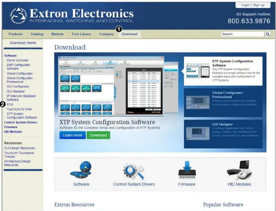
Figure 33. PCS Software Link on the Download Page of the Extron Website
- On the PCS page, click the Download button in the new features table (see figure 34, ①, on the next page).
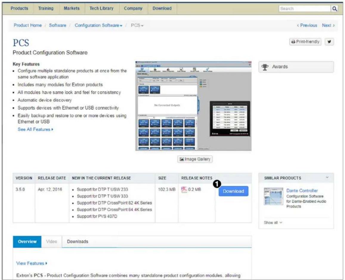
Figure 34. Download Button on the PCS Web Page
- On the Download Center page, fill in the required information, then click the Download PCS_vnxnxnxnn.exe button.
- If the File Download - Security Warning window appears, click Run to begin downloading the installer file.
NOTE: If you want to save the installation file to your computer hard drive to run later, click Save. On the Save As window that opens, save the setup file to the desired location. When you are ready to install the software, double-click on the PCS_vnxnxnxnn.exe icon, click Run on the download screen that opens, and restart this procedure at step 6.
If, instead, you see a Download icon at the bottom of the page, wait until the icon displays the name PCS_vnxnxnxnn.exe, then click it.
- On the next prompt window that opens, click Run to start the installation process.
- Follow the instructions on the InstallShield Wizard screens to complete the software program installation. By default the installation creates a folder called "Extron PCS" in one of the following locations on the computer (depending on the Windows version):
c:\Program Files (x86)\Extron\Extron PCS or
c:\Program Files\Extron\Extron PCS
If there is not already an Extron folder in your Program Files or Program Files x86 folder, the installation program creates it as well.
Starting the Configuration Program
In order to use the PCS software, the DSC must be connected to your computer via the front panel USB port (see Connecting for Remote Control on page 14) or the rear panel LAN port.
-
To start the configuration program, do either of the following:
-
Access the program from the Start menu on your computer as follows:
a. Click Start on your computer screen.
b. Select All Programs from the Start menu.
c. From the All Programs menu, select Extron Electronics/Extron Product Configuration Software/Extron Product Configuration Software. The Extron Product Configuration Software window opens.
- Double-click on the EAF.exe file, located on your computer at c:\Program Files [or Program Files(x86)]\Extron\Extron PCS.
- The first time you open the PCS software, the Tutorial screen appears, identifying items on the toolbar at the top of the PCS screen. When finished looking at the tutorial, click I Get It to close the screen. The Extron PCS window opens.
- In the Device Discovery panel of the PCS window, click on DSC HD-HD 4K A, DSC HD-HD 4K PLUS A, or DSC HD-HD 4K PLUS A xi (see figure 35, ①). You may need to scroll to locate it, depending on the number of devices listed. The Connect button in the bottom-right corner becomes available.
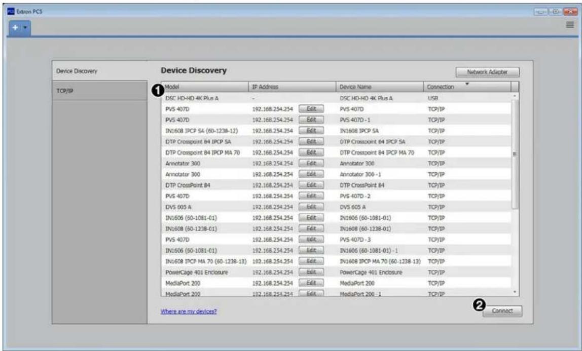
Figure 35. Device Discovery Panel
If your DSC does not appear in the Device Directory and you have an IP connection:
a. Click the TCP/IP button in the left panel of the Device Discovery screen. The TCP/IP login panel opens.
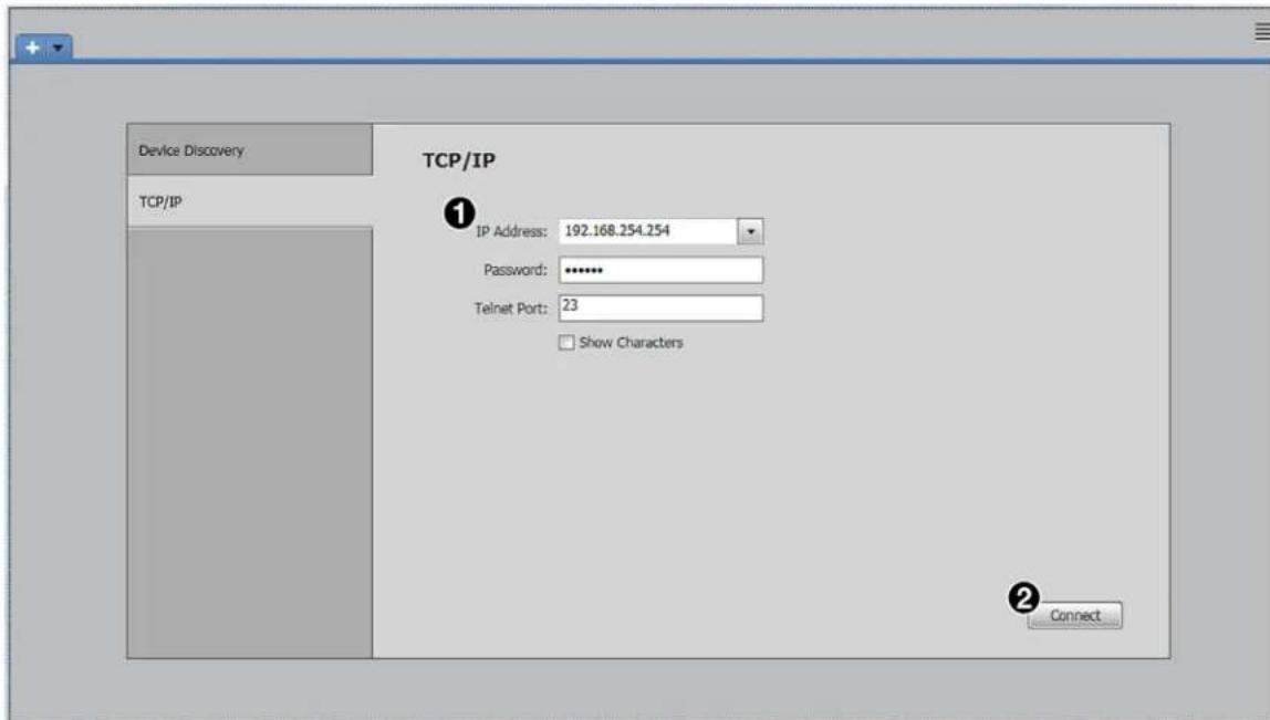
Figure 36. TCP/IP Login Panel
b. Enter the IP address where indicated (see figure 36, ①), and the password, if any.
- Click Connect (see figure 35, ②, on the previous page, or figure 36, ②) to open the DSC HD-HD 4K A Series main window (see figure 37 on the next page).
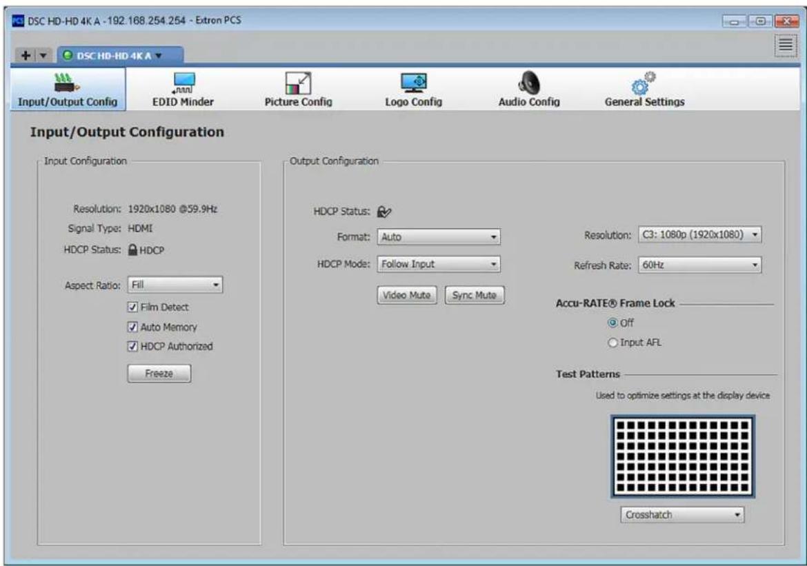
Figure 37. DSC HD-HD 4K A Main Window
See the DSC HD-HD 4K A Series help file, included in the PCS software, for instructions on using this software to configure the DSC.
Updating Firmware
Extron periodically updates product firmware. Before updating any Extron product to the latest revision level, be sure to read the supplied release notes or contact Extron Technical Support to determine if your product requires a firmware update.
You can update firmware using the PCS software (see the DSC HD-HD 4K A Series help file) or the DSC HD-HD 4K A Series web page (see DSC HD-HD 4K A Series Web Page, on the next page).
DSC HD-HD 4K A Series Web Page
The embedded DSC HD-HD 4K A Series web page enables you to monitor and adjust certain settings of the DSC through its Ethernet port, connected via a LAN or WAN and using a web browser such as Microsoft® Internet Explorer®. This factory-installed web page is always available and cannot be erased or overwritten.
Accessing the Web Page
To access the HTML page:
-
In the Address field of your web browser, enter the IP address of your unit. To obtain this address, do either of the following:
-
Press the front panel Menu button and select the Communications submenu. The current IP address is the fourth item in the right panel.
- Enter the View IP address SIS command: Esc CI ← on page 68. See SIS Commands, beginning on page 43, for information on entering these commands.
NOTE: If the local system administrators have not changed the IP address, use the factory-specified default 192.168.254.254 in this field.
-
Press the
key. The DSC checks to see if the web page is password protected. -
If the unit is not password protected, the web page opens.
- If the unit is password protected, the Authentication Required dialog box opens (see figure 38).
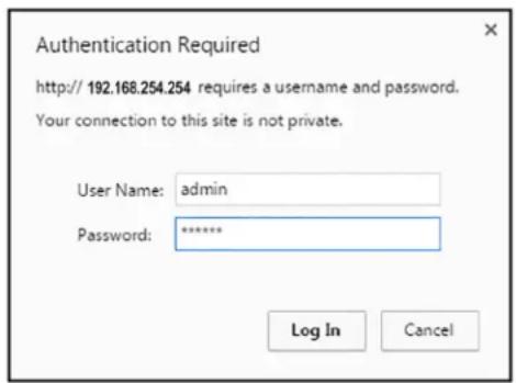
Figure 38. Example of a Network Password Dialog Box
- If an administrator or user password is required, enter admin or user in the User Name field and the password in the Password field. Click Log In.
Web Page Components
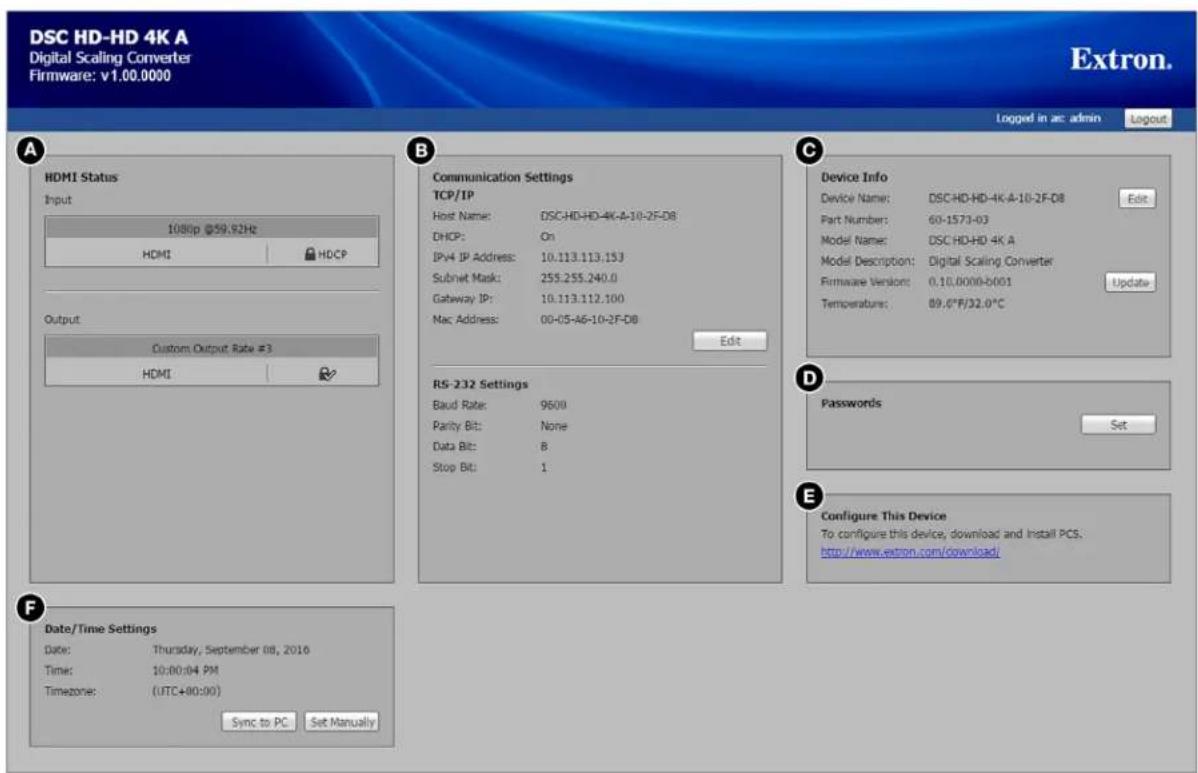
A HDMI Status
© Device Info
E Configure This Device
B Communication Settings
D Passwords
F Date/Time Settings
Figure 39. DSC HD-HD 4K PLUS A Web Page
NOTE: Figure 39 shows the web page for a DSC HD-HD 4K PLUS A, non-xi model. The DSC HD-HD 4K A model page is identical except for the product name in the upper-left corner of the page. The xi model page is also identical except that the HDMI Status panel contains information for two inputs and two outputs, and the product name displayed in the upper-left corner is DSC HD-HD 4K PLUS A xi.
The web pages for both models contain the following panels:
A HDMI Status — Shows the resolution and refresh rate of the HDMI (or DVI) input (see figure 40, ①) and output (③), the input HDCP encryption status (②) and the HDCP compliance of the attached sink (④).
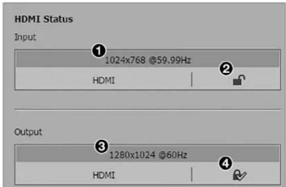
Figure 40. HDMI Status Panel for a DSC HD-HD 4K A and PLUS A
- Input panel:
- If the input signal is HDCP encrypted, the Input status field displays a closed lock icon followed by HDCP (see the illustration at right).

- If the input signal is NOT HDCP encrypted, the Input status field displays an open lock icon (2).
- If no device is connected to the HDMI input, the input status field displays a dash (−).
- Output panel:
- If the attached sink is HDCP compliant, the output status field displays a lock icon with a check mark (4).
- If the sink is non-HDCP compliant, this field displays an open lock icon with an X on it.
- If no device is connected to the output connector, the output status field displays a dash (−).
NOTE: Figure 40 on the previous page shows an HDMI Status panel for the DSC HD-HD 4K A Series non-xi models. The HDMI Status panel for the xi model displays information for two inputs and outputs.
B Communication Settings — This panel contains the current TCP/IP and RS-232 connection settings. It also has an Edit button that lets you access the IP settings for editing. The RS-232 settings are view-only and cannot be changed.
Editing the TCP/IP settings
- In the Communication Settings panel (see figure 39, B, on the previous page) click the Edit button. The following dialog box opens:
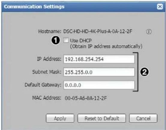
Figure 41. Communication Settings Dialog Box
- Enter the desired settings in the IP Address, Subnet Mask, and Default Gateway fields (see figure 41, ②). The Use DHCP checkbox must be cleared for you to edit these fields.
Alternatively, select the Use DHCP checkbox (1) to have the unit obtain its IP address from a DHCP server.
If you want to reset all IP settings to their factory defaults, click Reset to Default, then click Reset on the confirmation prompt that opens.
- Click Apply to confirm the settings and close the dialog box.
Device Info — Contains the device name, part number, model name and description, firmware version and build numbers, and the current internal temperature of the DSC unit. In this panel you can edit the device name and upload another version of firmware.
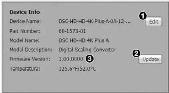
Figure 42. Device Info Panel
Changing the device name (TCP/IP Hostname)
- In the Device Info panel, click the Edit button (see figure 42, ①). The following dialog box opens:
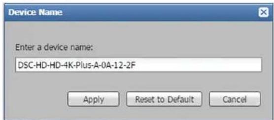
Figure 43. Device Name Dialog Box
- Enter a name for the DSC device.
If you want to reset the name to the factory default, click Reset to Default.
- Click Apply to confirm the new name and close the dialog box.
Updating firmware
The current firmware version number is displayed in the Firmware Version field (see figure 42, ③) of the Device Info panel.
-
Click the Update button (②). The Firmware Update dialog box opens.
-
In the dialog box, either click the Browse button to locate the firmware file on your computer (by default the file is stored at C:\Program Files (x86)\Extron\Firmware\DSC HD-HD 4K A Series after being downloaded from the Extron web page) and double-click the firmware file name, or enter the path to the firmware file in the Firmware field (see figure 44, ①).
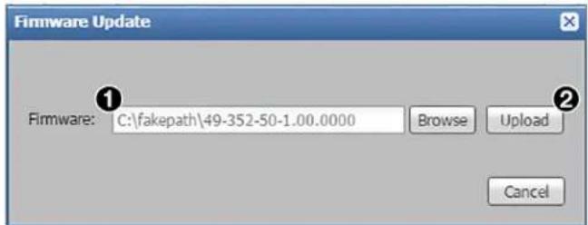
Figure 44. Firmware Update Dialog Box
- Click Upload to begin (see figure 44, ②, on the previous page). During the updating process, a window appears in the middle of the screen, showing messages giving the progress of the update: Initializing, Installing the Firmware, and Rebooting Device.
Figure 45. Firmware Update Message Window
When the update is completed, the message window closes and the message Firmware Upload Complete appears near the top of the screen.
Passwords — From this panel you can set and remove administrator and user passwords.
NOTES:
- An administrator password must be in place before a user password can be assigned.
- Passwords must contain 4 to 12 alphanumeric characters. Symbols and spaces are not allowed, and the passwords are case sensitive.
Setting a password
To assign a password:
- In the Passwords panel (see figure 39, D, on page 80) click Set. The Passwords dialog box opens (see figure 46).
- If requested, enter a Login ID. The default is Admin.
- Enter the new administrator password in the Administrator Password field (see figure 46, ①).
- Repeat the password in the Confirm Password field (2).
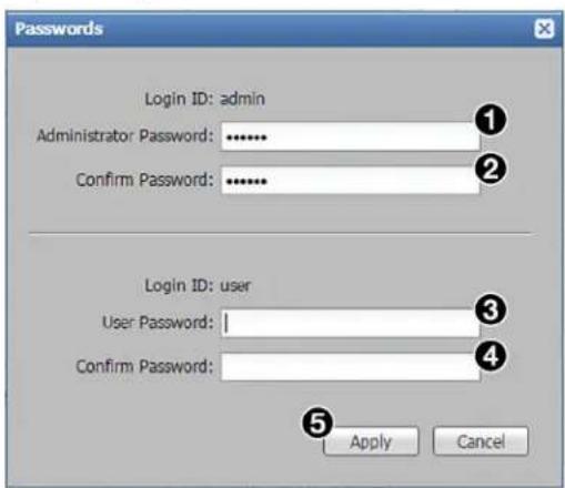
Figure 46. Passwords Dialog Box with Administrator Password Entered
- If you want to assign a user password, enter it in the User Password field (see figure 46, ③, on the previous page.
- Reenter the same user password in the next Confirm Password field (4).
- When finished, click the Apply button ( 5) to set the passwords.
To remove an assigned password:
- In the Administrator Password or User Password field, enter a single space.
- Enter a single space in the appropriate Confirm Password field.
- Click Apply.
E Configure This Device — This panel contains a link to the Extron website, Download page, from which you can download and install the PCS software program.
Date/Time Settings — In this panel you can view and set the unit date and time.
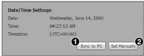
Figure 47. Date/Time Settings Panel
- To set the DSC HD-HD 4K PLUS A date and time to match that of your computer, click Sync to PC (see figure 47, 1). When the sync is completed, the message at right appears at the top of the screen.
- To set the date and time manually, click Set Manually (②) to open the Date and Time Settings dialog box (see figure 48).
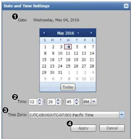
Figure 48. Date and Time Settings Dialog Box
Use the controls to set the date, time, and time zone as follows:
- Date — In the calendar, click on the number to select the day, the down arrow to select the month and year, the right and left arrows to move backward and forward through the months, or the Today button to select the current date (see figure 48, 1).
- Time — Click the up and down arrows for each field to set the hours, minutes, seconds, and AM or PM (see figure 48, 2, on the previous page).
- Time Zone — Select the time zone from the drop-down menu ( ③).
When finished entering settings, click Apply (4) to confirm them.
Special Characters
The HTML language reserves certain characters for specific functions. The DSC does not accept these characters as part of device names, passwords, or locally created file names. The following characters are not accepted:
$$ + \sim , @ = ^ {\prime} [ ] {} < > ^ {\prime}, ^ {\prime \prime};: | \backslash ? a n d {\text {space} }. $$
Mounting
This section contains information on mounting the DSC HD-HD 4K A Series scaler (see www.extron.com for available Extron mounting kits and ordering information).
The DSC HD-HD 4K A Series scalers can be mounted by any of the methods listed below. Follow the instructions provided with the mounting kit.
- Rack mounting: Attach the DSC to a standard 19-inch rack shelf. The following Underwriters Laboratories (UL) guidelines pertain to the installation of the DSC HD-HD 4K A series in a rack:
- Elevated operating ambient temperature — If the equipment is installed in a closed or multi-unit rack assembly, the operating ambient temperature of the rack environment may be greater than room ambient temperature. Therefore, install the equipment in an environment compatible with the maximum ambient temperature (TMA = +122 °F, +50 °C) specified by Extron.
- Reduced air flow — Install the equipment in the rack so that the amount of air flow required for safe operation of the equipment is not compromised.
- Mechanical loading — Mount the equipment in the rack so that uneven mechanical loading does not create a hazardous condition.
- Circuit overloading — When connecting the equipment to the supply circuit, consider the effect that circuit overloading might have on overcurrent protection and supply wiring. Consider equipment nameplate ratings when addressing this concern.
- Reliable earthing (grounding) — Maintain reliable grounding of rack-mounted equipment. Pay particular attention to supply connections other than direct connections to the branch circuit (such as the use of power strips).
- Under-furniture mounting: Mount the DSC under the surface of a desk, table, or podium.
- Through-furniture mounting: Mount the DSC through a table or desk in which a hole has been cut to enable access to the front panel.
- Free-standing: Attach the included four rubber feet to the bottom of the DSC in the four corners and place the unit on furniture as desired.
Extron Warranty
Extron Electronics warrants this product against defects in materials and workmanship for a period of three years from the date of purchase. In the event of malfunction during the warranty period attributable directly to faulty workmanship and/or materials, Extron Electronics will, at its option, repair or replace said products or components, to whatever extent it shall deem necessary to restore said product to proper operating condition, provided that it is returned within the warranty period, with proof of purchase and description of malfunction to:
USA, Canada, South America, and Central America:
Extron Electronics
1230 South Lewis Street
Anaheim, CA 92805
U.S.A.
Japan:
Extron Electronics, Japan
Kyodo Building, 16 Ichibancho
Chiyoda-ku, Tokyo 102-0082
Japan
Europe and Africa:
Extron Europe
Hanzeboulevard 10
3825 PH Amersfoort
The Netherlands
China:
Extron China
686 Ronghua Road
Songjiang District
Shanghai 201611
China
Asia:
Extron Asia Pte Ltd
135 Joo Seng Road, #04-01
PM Industrial Bldg.
Singapore 368363
Singapore
Middle East:
Extron Middle East
Dubai Airport Free Zone
F13, PO Box 293666
United Arab Emirates, Dubai
This Limited Warranty does not apply if the fault has been caused by misuse, improper handling care, electrical or mechanical abuse, abnormal operating conditions, or if modifications were made to the product that were not authorized by Extron.
NOTE: If a product is defective, please call Extron and ask for an Application Engineer to receive an RA (Return Authorization) number. This will begin the repair process.
USA: 714.491.1500 or 800.633.9876
Europe: 31.33.453.4040
Asia: 65.6383.4400
Japan: 81.3.3511.7655
Units must be returned insured, with shipping charges prepaid. If not insured, you assume the risk of loss or damage during shipment. Returned units must include the serial number and a description of the problem, as well as the name of the person to contact in case there are any questions.
Extron Electronics makes no further warranties either expressed or implied with respect to the product and its quality, performance, merchantability, or fitness for any particular use. In no event will Extron Electronics be liable for direct, indirect, or consequential damages resulting from any defect in this product even if Extron Electronics has been advised of such damage.
Please note that laws vary from state to state and country to country, and that some provisions of this warranty may not apply to you.
| Extron Headquarters+1.800.633.9876 (Inside USA/Canada Only)Extron USA - West Extron USA - East+1.714.491.1500 +1.919.850.1000+1.714.491.1517 FAX +1.919.850.1001 FAX | Extron Europe+800.3987.6673(Inside Europe Only)+31.33.453.4040+31.33.453.4050 FAX | Extron Asia+65.6383.4400+65.6383.4864 FAX | Extron Japan+81.3.3511.7656+81.3.3511.7656 FAX | Extron China+86.21.3760.1568+86.21.3760.1566 FAX | Extron Middle East+971.4.299.1800+971.4.299.1880 FAX | Extron Australia+61.8.8351.2188+61.8.8351.2511 FAX | Extron India1800.3070.3777(Inside India Only)+91.80.3055.3777+91.80.3055.3737 FAX |
- DSC HD-HD 4K A Series
- Safety Instructions
- Safety Instructions • English
- Trademarks
- FCC Class A Notice
- Battery Notice
- Conventions Used in this Guide
- Notifications
- Software Commands
- Specifications Availability
- Extron Glossary of Terms
- Contents
- Introduction.... 1
- Installation....6
- Operation....18
- Remote Configuration and Control....43
- Mounting 86
- Introduction
- About This Guide
- About the DSC HD-HD 4K A Series
- Features
- Installation
- ATTENTION:
- Connecting for 4K Processing
- Single Input to Single Output
- Single Input to Dual Outputs (xi Model Only)
- Two Input Columns to a Single Output (xi Model Only)
- Single Input to Two Output Columns (xi Model Only)
- Two Inputs to Two Side-by-Side Outputs (xi Model Only)
- Securing the HDMI Connector Using the LockIt Cable Lacing Bracket
- Connecting for Remote Control
- Connecting to the RS-232 Port
- Connecting to the USB Config Port
- Operation
- Front Panel Features
- On-screen Display Menu
- Menu Overview
- Using the Front Panel Buttons with the OSD Menu
- Using the OSD Menu
- NOTES:
- Quick Setup Submenu
- Picture Controls Submenu
- Adjusting the picture controls
- Image Position
- Figure 23. Example of a Selected Picture Controls Submenu Item
- Input Submenu
- Figure 25. Custom EDID Slots List Example
- Output Submenu
- To select an output rate:
- Audio Submenu
- Advanced Submenu
- Communications Submenu
- Setting the IP, subnet mask, and gateway addresses
- Device Info Screen
- Auto-Image
- Changing the Output Resolution and Refresh Rate
- Custom Rates
- Resetting the Output Rate
- Power Save Mode
- Presets
- Auto Memories
- Input Presets
- Saving a preset when using a matrix switcher
- Locking the Front Panel (Executive Mode)
- Resetting
- Remote Configuration and Control
- SIS Commands
- Copyright Information
- DSC-initiated Messages
- Error Responses
- Using the Command and Response Table
- Symbol Definitions
- Command and Response Table for SIS Commands
- Product Configuration Software (PCS) Program
- Downloading the PCS Software from the Website
- Starting the Configuration Program
- If your DSC does not appear in the Device Directory and you have an IP connection:
- Updating Firmware
- DSC HD-HD 4K A Series Web Page
- Accessing the Web Page
- - Input panel:
- - Output panel:
- Editing the TCP/IP settings
- Changing the device name (TCP/IP Hostname)
- Setting a password
- To remove an assigned password:
- Special Characters
- Mounting
- Extron Warranty
- USA, Canada, South America, and Central America:
- Japan:
- Europe and Africa:
- China:
- Asia:
- Middle East:
Brand : Extron
Model : DSC HD-HD 4K PLUS A xi
Category : Audiovisual Equipment