Transarc 300i - Welding machine Cigweld - Free user manual and instructions
Find the device manual for free Transarc 300i Cigweld in PDF.


| Product Type | Multi-Process Welding Machine (MMA, TIG, MIG) |
| Brand | Cigweld |
| Model | Transarc 300i |
| Dimensions (L x W x H) | 550 mm x 280 mm x 450 mm |
| Weight | 25 kg |
| Power Supply | 415V, 3-Phase, 50/60 Hz |
| Output Current Range | 10 A - 300 A |
| Duty Cycle | 60% @ 300 A (40°C) |
| Welding Processes | MMAW (Stick), GTAW (TIG), GMAW (MIG/MAG), FCAW |
| Open Circuit Voltage | 70 V (MMA), 60 V (TIG), 50 V (MIG) |
| Efficiency | > 85% |
| Protection Class | IP23 |
| Insulation Class | H |
| Cooling System | Fan-cooled |
| Regulation | IGBT Inverter Technology |
| Arc Force | Adjustable (0-10) |
| Hot Start | Adjustable (0-10) |
| Anti-Stick | Yes |
| VRD (Voltage Reduction Device) | Yes, for safety |
| Maintenance | Regular cleaning of air vents, check cables and torch, replace consumables as needed |
| Safety | Overload protection, thermal protection, earth leakage protection |
| Spare Parts & Repairability | Available through Cigweld distributors: circuit boards, fans, switches, torch, earth clamp, cables |
| General Information | User manual contains safety instructions, setup, operation, maintenance, and troubleshooting guidelines |
Frequently Asked Questions - Transarc 300i Cigweld
User questions about Transarc 300i Cigweld
0 question about this device. Answer the ones you know or ask your own.
Ask a new question about this device
Download the instructions for your Welding machine in PDF format for free! Find your manual Transarc 300i - Cigweld and take your electronic device back in hand. On this page are published all the documents necessary for the use of your device. Transarc 300i by Cigweld.
USER MANUAL Transarc 300i Cigweld
natural_image
Blue and black OGNED Professional welding machine with 300V power input and control panel (no visible text or symbols on main body)Manual
Revision: AA
Issue Date: January 15, 2008
Manual No: 0-4956
Operating Features:


WE APPRECIATE YOUR BUSINESS!
Congratulations on your new CIGWELD ^® product. We are proud to have you as our customer and will strive to provide you with the best service and reliability in the industry. This product is backed by our extensive warranty and world-wide service network. To locate your nearest distributor or service agency call 800-752-7621, or visit us on the web at www.cigweld.au.com.
This Operating Manual has been designed to instruct you on the correct use and operation of your Cigwe® product. Your satisfaction with this product and its safe operation is our ultimate concern. Therefore, please take the time to read the entire manual, especially the Safety Precautions. They will help you to avoid potential hazards that may exist when working with this product.
YOU ARE IN GOOD COMPANY!
The Brand of Choice for Contractors and Fabricators Worldwide.
Cigweld ^® is a Global Brand of Arc Welding Products for Thermadyne Industries Inc. We manufacture and supply to major welding industry sectors worldwide including; Manufacturing, Construction, Mining, Automotive, Aerospace, Engineering, Rural and DIY/Hobbyist.
We distinguish ourselves from our competition through market-leading, dependable products that have stood the test of time. We pride ourselves on technical innovation, competitive prices, excellent delivery, superior customer service and technical support, together with excellence in sales and marketing expertise.
Above all, we are committed to develop technologically advanced products to achieve a safer working environment within the welding industry.
Read and understand this entire Manual and your employer's safety practices before installing, operating, or servicing the equipment.
While the information contained in this Manual represents the Manufacturer's best judgment, the Manufacturer assumes no liability for its use.
Operating Manual Number 0-4956 for:
Transarc 300 Si Inverter Welding Power Supply Part No. 625781
Published by:
Thermadyne Industries, Inc.
82 Benning Street
West Lebanon, New Hampshire, USA 03784
(603) 298-5711
www.thermadyne.com
Copyright © 2008 by
Thermadyne Industries, Inc.
® All rights reserved.
Reproduction of this work, in whole or in part, without written permission of the publisher is prohibited.
The publisher does not assume and hereby disclaims any liability to any party for any loss or damage caused by any error or omission in this Manual, whether such error results from negligence, accident, or any other cause.
Publication Date: January 15, 2008
Record the following information for Warranty purposes:
Where Purchased: ____
Purchase Date: ____
Equipment Serial #: ____
Table of Contents
SECTION 1:
SAFETY INSTRUCTIONS AND WARNINGS .... 1-1
1.01 Arc Welding Hazards 1-1
1.02 Principal Safety Standards 1-4
1.03 Precautions De Securite En Soudage A L'arc ....1-5
1.04 Dangers relatifs au soudage à l'arc 1-5
1.05 Principales Normes De Securite ....1-8
1.06 Declaration Of Conformity 1-9
SECTION 2:
INTRODUCTION AND DESCRIPTION 2-1
2.01 How To Use This Manual 2-1
2.02 Equipment Identification 2-1
2.03 Receipt Of Equipment 2-1
2.04 Symbol Chart 2-2
2.05 Description 2-3
2.06 Functional Block Diagrams 2-3
2.07 Transporting Methods 2-4
SECTION 3:
INSTALLATION RECOMMENDATIONS 3-1
3.01 Environment 3-1
3.02 Location 3-1
3.03 Electrical Input Connections 3-1
3.04 Mains Supply Voltage Requirements 3-2
3.05 Specifications 3-3
3.05 Duty Cycle 3-4
SECTION 4:
OPERATOR CONTROLS 4-1
4.01 Transarc 300 Si Controls 4-1
4.02 Weld Parameter Description 4-2
4.03 Weld Parameters for Transarc 300 Si 4-3
4.04 Power Source Features 4-4
SECTION 5:
SET-UP FOR SMAW (STICK) AND GTAW (TIG) 5-1
SECTION 6:
6.01 Stick Welding 6-1
6.02 DC LIFT TIG Welding 6-1
Table of Contents
SECTION 7:
BASIC TIG WELDING GUIDE 7-1
7.01 Electrode Polarity 7-1
7.02 Tungsten Electrode Current Ranges 7-1
7.03 Tungsten Electrode Types 7-1
7.04 Guide for Selecting Filler Wire Diameter 7-1
7.05 Shielding Gas Selection 7-2
7.06 TIG Welding Parameters for Low Carbon & Low Alloy Steel Pipe .....7-2
SECTION 8:
BASIC ARC WELDING GUIDE 8-1
8.01 Electrode Polarity 8-1
8.02 Effects of Stick Welding Various Materials 8-1
SECTION 9:
ROUTINE MAINTENANCE 9-1
SECTION 10:
BASIC TROUBLESHOOTING 10-1
10.01 TIG Welding Problems 10-1
10.02 Stick Welding Problems 10-3
10.03 Power Source Problems 10-4
SECTION 11:
VOLTAGE REDUCTION DEVICE (VRD) 11-1
11.01 VRD Specification ....11-1
11.02 VRD Maintenance 11-1
SECTION 12:
POWER SOURCE ERROR CODES 12-1
APPENDIX 1: OPTIONS AND ACCESSORIES ...... A-1
APPENDIX 2: INTERCONNECT DIAGRAM ...... A-3
CIQWELD LIMITED WARRANTY
Terms of Warranty – January 2008
Warranty Schedule – January 2008
GLOBAL CUSTOMER SERVICE CONTACT INFORMATION ......Inside Rear Cover
SECTION 1: SAFETY INSTRUCTIONS AND WARNINGS
WARNING
PROTECT YOURSELF AND OTHERS FROM POSSIBLE SERIOUS INJURY OR DEATH. KEEP CHILDREN AWAY. PACEMAKER WEARERS KEEP AWAY UNTIL CONSULTING YOUR DOCTOR. DO NOT LOSE THESE INSTRUCTIONS. READ OPERATING/INSTRUCTION MANUAL BEFORE INSTALLING, OPERATING OR SERVICING THIS EQUIPMENT.
Welding products and welding processes can cause serious injury or death, or damage to other equipment or property, if the operator does not strictly observe all safety rules and take precautionary actions.
Safe practices have developed from past experience in the use of welding and cutting. These practices must be learned through study and training before using this equipment. Some of these practices apply to equipment connected to power lines; other practices apply to engine driven equipment. Anyone not having extensive training in welding and cutting practices should not attempt to weld.
Safe practices are outlined in the American National Standard Z49.1 entitled: SAFETY IN WELDING AND CUTTING. This publication and other guides to what you should learn before operating this equipment are listed at the end of these safety precautions. HAVE ALL INSTALLATION, OPERATION, MAINTENANCE, AND REPAIR WORK PERFORMED ONLY BY QUALIFIED PEOPLE.
1.01 Arc Welding Hazards

WARNING
ELECTRIC SHOCK can kill.
Touching live electrical parts can cause fatal shocks or severe burns. The electrode and work circuit is electrically live whenever the output is on. The input power circuit and machine internal circuits are also live when power is on. In semiautomatic or automatic wire welding, the wire, wire reel, drive roll housing, and all metal parts touching the welding wire are electrically live. Incorrectly installed or improperly grounded equipment is a hazard.
- Do not touch live electrical parts.
- Wear dry, hole-free insulating gloves and body protection.
- Insulate yourself from work and ground using dry insulating mats or covers.
- Disconnect input power or stop engine before installing or servicing this equipment. Lock input power disconnect switch open, or remove line fuses so power cannot be turned on accidentally.
- Properly install and ground this equipment according to its Owner's Manual and national, state, and local codes.
- Turn off all equipment when not in use. Disconnect power to equipment if it will be left unattended or out of service.
- Use fully insulated electrode holders. Never dip holder in water to cool it or lay it down on the ground or the work surface. Do not touch holders connected to two welding machines at the same time or touch other people with the holder or electrode.
- Do not use worn, damaged, undersized, or poorly spliced cables.
- Do not wrap cables around your body.
-
Ground the workpiece to a good electrical (earth) ground.
-
Do not touch electrode while in contact with the work (ground) circuit.
- Use only well-maintained equipment. Repair or replace damaged parts at once.
- In confined spaces or damp locations, do not use a welder with AC output unless it is equipped with a voltage reducer. Use equipment with DC output.
- Wear a safety harness to prevent falling if working above floor level.
- Keep all panels and covers securely in place.
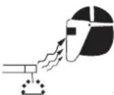
WARNING
ARC RAYS can burn eyes and skin; NOISE can damage hearing. Arc rays from the welding process produce intense heat and strong ultraviolet rays that can burn eyes and skin. Noise from some processes can damage hearing.
- Wear a welding helmet fitted with a proper shade of filter (see ANSI Z49.1 listed in Safety Standards) to protect your face and eyes when welding or watching.
- Wear approved safety glasses. Side shields recommended.
- Use protective screens or barriers to protect others from flash and glare; warn others not to watch the arc.
- Wear protective clothing made from durable, flame-resistant material (wool and leather) and foot protection.
- Use approved ear plugs or ear muffs if noise level is high.
TRANSARC 300 Si
WARNING
FUMES AND GASES can be hazardous to your health. Welding produces fumes and gases. Breathing these fumes and gases can be hazardous to your health.
- Keep your head out of the fumes. Do not breath the fumes.
- If inside, ventilate the area and/or use exhaust at the arc to remove welding fumes and gases.
- If ventilation is poor, use an approved air-supplied respirator.
- Read the Material Safety Data Sheets (MSDSs) and the manufacturer's instruction for metals, consumables, coatings, and cleaners.
- Work in a confined space only if it is well ventilated, or while wearing an air-supplied respirator. Shielding gases used for welding can displace air causing injury or death. Be sure the breathing air is safe.
- Do not weld in locations near degreasing, cleaning, or spraying operations. The heat and rays of the arc can react with vapors to form highly toxic and irritating gases.
-
Do not weld on coated metals, such as galvanized, lead, or cadmium plated steel, unless the coating is removed from the weld area, the area is well ventilated, and if necessary, while wearing an air-supplied respirator. The coatings and any metals containing these elements can give off toxic fumes if welded.
-
Protect yourself and others from flying sparks and hot metal.
- Do not weld where flying sparks can strike flammable material.
- Remove all flammables within 35 ft (10.7 m) of the welding arc. If this is not possible, tightly cover them with approved covers.
- Be alert that welding sparks and hot materials from welding can easily go through small cracks and openings to adjacent areas.
- Watch for fire, and keep a fire extinguisher nearby.
- Be aware that welding on a ceiling, floor, bulkhead, or partition can cause fire on the hidden side.
- Do not weld on closed containers such as tanks or drums.
- Connect work cable to the work as close to the welding area as practical to prevent welding current from traveling long, possibly unknown paths and causing electric shock and fire hazards.
- Do not use welder to thaw frozen pipes.
- Remove stick electrode from holder or cut off welding wire at contact tip when not in use.
WARNING
FLYING SPARKS AND HOT METAL can cause injury. Chipping and grinding cause flying metal. As welds cool, they can throw off slag.
- Wear approved face shield or safety goggles. Side shields recommended.
- Wear proper body protection to protect skin.
WARNING
WELDING can cause fire or explosion.
Sparks and spatter fly off from the welding arc. The flying sparks and hot metal, weld spatter, hot workpiece, and hot equipment can cause fires and burns. Accidental contact of electrode or welding wire to metal objects can cause sparks, overheating, or fire.
Eye protection filter shade selector for welding or cutting (goggles or helmet), from AWS A6.2-73.
| Welding or cutting | Electrode Size | Filter | Welding or cutting | Electrode Size | Filter |
| Torch soldering 2 | Gas metal-arc | ||||
| Torch brazing 3 or 4 Non-ferrous base metal All 11 | |||||
| Oxygen Cutting | Ferrous base metal All 12 | ||||
| Light Under 1 in., 25 mm 3 or 4 | Gas tungsten arc welding | All 12 | |||
| Medium | 1 to 6 in., 25-150 mm | 4 or 5 | (TIG) | All | 12 |
| Heavy | Over 6 in., 150 mm | 5 or 6 | Atomic hydrogen welding | All | 12 |
| Gas welding | Carbon arc welding | All 12 | |||
| Light Under 1/8 in., 3 mm 4 or 5 | Plasma arc welding | ||||
| Medium | 1/8 to 1/2 in., 3-12 mm | 5 or 6 | Carbon arc air gouging | ||
| Heavy | Over 1/2 in., 12 mm | 6 or 8 | Light | 12 | |
| Shielded metal-arc | Under 5/32 in., 4 mm | 10 | Heavy | 14 | |
| 5/32 to 1/4 in., | 12 | Plasma arc cutting | |||
| Over 1/4 in., 6.4 mm | 14 | Light | Under 300 Amp | 9 | |
| Medium | 300 to 400 Amp | 12 | |||
| Heavy | Over 400 Amp | 14 | |||
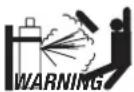
CYLINDERS can explode if damaged.
Shielding gas cylinders contain gas under high pressure. If damaged, a cylinder can explode. Since gas cylinders are normally part of the welding process, be sure to treat them carefully.
- Protect compressed gas cylinders from excessive heat, mechanical shocks, and arcs.
- Install and secure cylinders in an upright position by chaining them to a stationary support or equipment cylinder rack to prevent falling or tipping.
- Keep cylinders away from any welding or other electrical circuits.
- Never allow a welding electrode to touch any cylinder.
- Use only correct shielding gas cylinders, regulators, hoses, and fittings designed for the specific application; maintain them and associated parts in good condition.
- Turn face away from valve outlet when opening cylinder valve.
- Keep protective cap in place over valve except when cylinder is in use or connected for use.
- Read and follow instructions on compressed gas cylinders, associated equipment, and CGA publication P-1 listed in Safety Standards.

WARNING
Engines can be dangerous.

ENGINE EXHAUST GASES can kill.
Engines produce harmful exhaust gases.
- Use equipment outside in open, well-ventilated areas.
- If used in a closed area, vent engine exhaust outside and away from any building air intakes.

WARNING
ENGINE FUEL can cause fire or explosion.
Engine fuel is highly flammable.
- Stop engine before checking or adding fuel.
- Do not add fuel while smoking or if unit is near any sparks or open flames.
- Allow engine to cool before fueling. If possible, check and add fuel to cold engine before beginning job.
- Do not overfill tank — allow room for fuel to expand.
- Do not spill fuel. If fuel is spilled, clean up before starting engine.

MOVING PARTS can cause injury.
Moving parts, such as fans, rotors, and belts can cut fingers and hands and catch loose clothing.
- Keep all doors, panels, covers, and guards closed and securely in place.
- Stop engine before installing or connecting unit.
- Have only qualified people remove guards or covers for maintenance and troubleshooting as necessary.
- To prevent accidental starting during servicing, disconnect negative (-) battery cable from battery.
- Keep hands, hair, loose clothing, and tools away from moving parts.
- Reinstall panels or guards and close doors when servicing is finished and before starting engine.

WARNING
SPARKS can cause BATTERY GASES TO EXPLODE; BATTERY ACID can burn eyes and skin.
Batteries contain acid and generate explosive gases.
- Always wear a face shield when working on a battery.
- Stop engine before disconnecting or connecting battery cables.
- Do not allow tools to cause sparks when working on a battery.
- Do not use welder to charge batteries or jump start vehicles.
- Observe correct polarity (+ and −) on batteries.

WARNING
STEAM AND PRESSURIZED HOT COOLANT can burn face, eyes, and skin.
The coolant in the radiator can be very hot and under pressure.
- Do not remove radiator cap when engine is hot. Allow engine to cool.
- Wear gloves and put a rag over cap area when removing cap.
- Allow pressure to escape before completely removing cap.

WARNING
This product, when used for welding or cutting, produces fumes or gases which contain chemicals know to the State of California to cause birth defects and, in some cases, cancer. (California Health & Safety code Sec. 25249.5 et seq.)
NOTE
Considerations About Welding And The Effects of Low
Frequency Electric and Magnetic Fields
The following is a quotation from the General Conclusions Section of the U.S. Congress, Office of Technology Assessment, Biological Effects of Power Frequency Electric & Magnetic Fields - Background Paper, OTA-BP-E-63 (Washington, DC: U.S. Government Printing Office, May 1989):
“...there is now a very large volume of scientific findings based on experiments at the cellular level and from studies with animals and people which clearly establish that low frequency magnetic fields and interact with, and produce changes in, biological systems. While most of this work is of very high quality, the results are complex. Current scientific understanding does not yet allow us to interpret the evidence in a single coherent framework. Even more frustrating, it does not yet allow us to draw definite conclusions about questions of possible risk or to offer clear science-based advice on strategies to minimize or avoid potential risks.”
To reduce magnetic fields in the workplace, use the following procedures.
- Keep cables close together by twisting or taping them.
- Arrange cables to one side and away from the operator.
- Do not coil or drape cable around the body.
- Keep welding power source and cables as far away from body as practical.
ABOUT PACEMAKERS:
The above procedures are among those also normally recommended for pacemaker wearers. Consult your doctor for complete information.
1.02 Principal Safety Standards
Safety in Welding and Cutting, ANSI Standard Z49.1, from American Welding Society, 550 N.W. LeJeune Rd., Miami, FL 33126.
Safety and Health Standards, OSHA 29 CFR 1910, from Superintendent of Documents, U.S. Government Printing Office, Washington, D.C. 20402.
Recommended Safe Practices for the Preparation for Welding and Cutting of Containers That Have Held Hazardous Substances, American Welding Society Standard AWS F4.1, from American Welding Society, 550 N.W. LeJeune Rd., Miami, FL 33126.
National Electrical Code, NFPA Standard 70, from National Fire Protection Association, Batterymarch Park, Quincy, MA 02269.
Safe Handling of Compressed Gases in Cylinders, CGA Pamphlet P-1, from Compressed Gas Association, 1235 Jefferson Davis Highway, Suite 501, Arlington, VA 22202.
Code for Safety in Welding and Cutting, CSA Standard W117.2, from Canadian Standards Association, Standards Sales, 178 Rexdale Boulevard, Rexdale, Ontario, Canada M9W 1R3.
Safe Practices for Occupation and Educational Eye and Face Protection, ANSI Standard Z87.1, from American National Standards Institute, 1430 Broadway, New York, NY 10018.
Cutting and Welding Processes, NFPA Standard 51B, from National Fire Protection Association, Batterymarch Park, Quincy, MA 02269.
1.03 DECLARATION OF CONFORMITY
Manufacturer: CIGWELD
Address: 71 Gower St, Preston
Victoria 3072
Australia


Description of equipment: Welding Equipment (GMAW, MMAW, GTAW). Including, but not limited to CIGWELD Transtig 200 Pi, Transtig 200 AC/DC, Transarc 300 Si, Transtig 300 Pi, Transtig 300 AC/DC, Transmig 400 i and associated accessories.
Serial numbers are unique with each individual piece of equipment and details description, parts used to manufacture a unit and date of manufacture.
The equipment conforms to all applicable aspects and regulations of the ‘Low Voltage Directive’ (Directive 73/23/EU, as recently changed in Directive 93/68/EU and to the National legislation for the enforcement of the Directive.
National Standard and Technical Specifications
The product is designed and manufactured to a number of standards and technical requirements among them are:
- AS/NZS 3652-(EMC Directive EN50199) applicable to arc welding equipment - generic emissions and regulations.
- EN60974-1 applicable to welding equipment and associated accessories.
- AS60974.1 applicable to welding equipment and associated accessories.
Extensive product design verification is conducted at the manufacturing facility as part of the routine design and manufacturing process, to ensure the product is safe and performs as specified. Rigorous testing is incorporated into the manufacturing process to ensure the manufactured product meets or exceeds all design specifications.
CIGWELD has been manufacturing and merchandising an extensive equipment range with superior performance, ultra safe operation and world class quality for more than 30 years and will continue to achieve excellence.
NOTES
SECTION 2: INTRODUCTION AND DESCRIPTION
2.01 How To Use This Manual
This Owner's Manual applies to just specification or part numbers listed on page i.
To ensure safe operation, read the entire manual, including the chapter on safety instructions and warnings.
Throughout this manual, the words WARNING, CAUTION, and NOTE may appear. Pay particular attention to the information provided under these headings. These special annotations are easily recognized as follows:

A WARNING gives information regarding possible personal injury.

A CAUTION refers to possible equipment damage.
NOTE
A NOTE offers helpful information concerning certain operating procedures.
Additional copies of this manual may be purchased by contacting Cigweld at the address and phone number in your area listed in the inside back cover of this manual. Include the Owner's Manual number and equipment identification numbers.
Electronic copies of this manual can also be downloaded at no charge in Acrobat PDF format by going to the
Cigweld web site listed below and clicking on the Literature Library link:
http://www.cigweld.au.com
2.02 Equipment Identification
The unit's identification number (specification or part number), model, and serial number usually appear on a nameplate attached to the control panel. In some cases, the nameplate may be attached to the rear panel. Equipment which does not have a control panel such as gun and cable assemblies is identified only by the specification or part number printed on the shipping container. Record these numbers on the bottom of page i for future reference.
2.03 Receipt Of Equipment
When you receive the equipment, check it against the invoice to make sure it is complete and inspect the equipment for possible damage due to shipping. If there is any damage, notify the carrier immediately to file a claim. Furnish complete information concerning damage claims or shipping errors to the location in your area listed in the inside back cover of this manual.
Include all equipment identification numbers as described above along with a full description of the parts in error.
Move the equipment to the installation site before un-crating the unit. Use care to avoid damaging the equipment when using bars, hammers, etc., to un-crate the unit.
2.04 Symbol Chart
Note that only some of these symbols will appear on your model.
| On | 1~ | Single Phase | oip | Wire Feed Function | |||
 | Off | 3~ | Three Phase | oio | Wire Feed Towards Workpiece With Output Voltage Off. | ||
| Dangerous Voltage | 3-200E | Three Phase Static Frequency Converter-Transformer-Rectifier | Welding Gun | ||||
 | Increase/Decrease | Remote | Purging Of Gas | ||||
 | Circuit Breaker | X | Duty Cycle | Continuous Weld Mode | |||
 | AC Auxiliary Power | % | Percentage | Spot Weld Mode | |||
 | Fuse | Panel/Local | Spot Time | ||||
 | Amperage | Shielded Metal Arc Welding (SMAW) | Preflow Time | ||||
 | Voltage | Gas Metal Arc Welding (GMAW) | Postflow Time | ||||
 | Hertz (cycles/sec) | Gas Tungsten Arc Welding (GTAW) | 2 Step Trigger OperationPress to initiate wirefeed and welding, release to stop. | ||||
| Frequency | Air Carbon Arc Cutting (CAC-A) | ||||||
 | Negative | Constant Current | 4 Step Trigger OperationPress and hold for preflow, release to start arc. Press to stop arc, and hold for preflow. | ||||
| Positive | Constant Voltage Or Constant Potential | ||||||
 | Direct Current (DC) | High Temperature | Burnback Time | ||||
 | Protective Earth (Ground) | Fault Indication | Disturbance In Ground System | ||||
 | Line | Arc Force | IPM | Inches Per Minute | |||
 | Line Connection | Touch Start (GTAW) | MPM | Meters Per Minute | |||
| Auxiliary Power | Variable Inductance | ||||||
| Receptacle Rating-Auxiliary Power | Voltage Input | ||||||
2.05 Description
The Cigweld Model Transarc 300 Si is a self contained three-phase DC arc welding power source with Constant Current (CC) output characteristics. This unit is equipped with a Digital Volt/Amperage Meter and lift arc starter for use with Gas Tungsten Arc Welding (GTAW) and Shielded Metal Arc Welding (SMAW) processes. The power source is totally enclosed in an impact resistant, flame resistant and non-conductive plastic case.
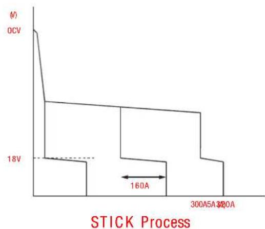
line
| Time (s) | Voltage (V) | | -------- | ----------- | | 0 | 0 | | 160 | 18 | | 300 | 30 |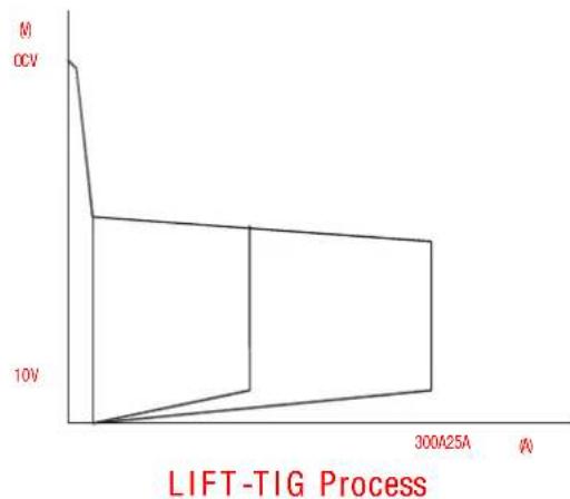
line
| Time (A) | Voltage (V) | | -------- | ----------- | | 0 | 0 | | 5 | 10 | | 10 | 20 | | 300 | 20 |Figure 1 - Transarc 300 Si volt-ampere curve
NOTE
Volt-Ampere curves show the maximum Voltage and Amperage output capabilities of the welding power source. Curves of other settings will fall between the curves shown.
2.06 Functional Block Diagrams
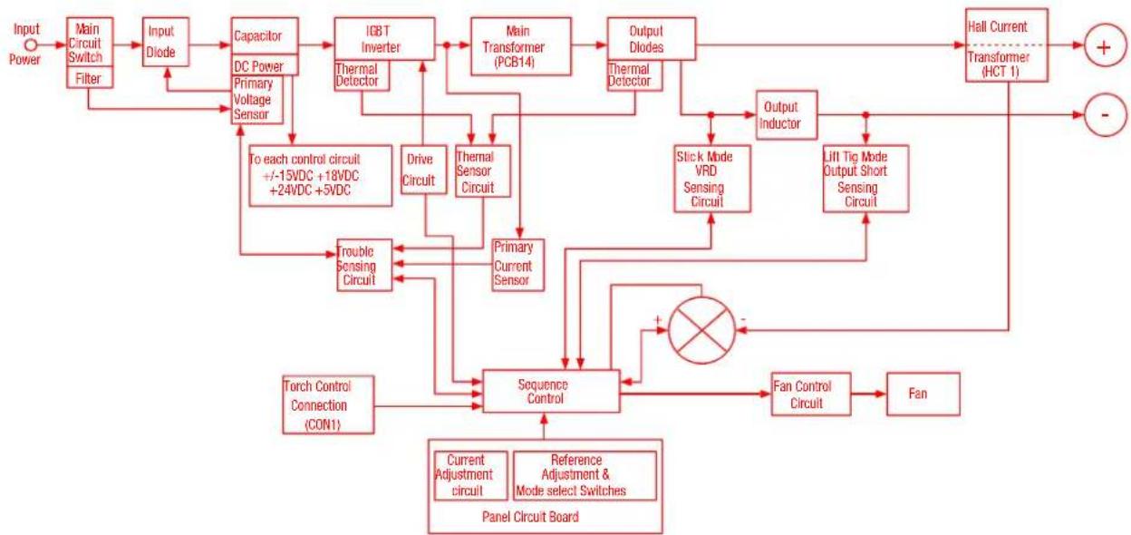
Figure 2 illustrates the functional block diagram of the Transarc 300 Si power source.
flowchart
graph TD
    A["Input Power"] --> B["Main Circuit Switch Filter"]
    B --> C["Input Diode"]
    C --> D["Capacitor"]
    D --> E["DC Power Primary Voltage Sensor"]
    E --> F["IGBT Inverter"]
    F --> G["Main Transformer (PCB14)"]
    G --> H["Output Diodes"]
    H --> I["Hall Current Transformer (HCT 1)"]
    I --> J["+"]
    I --> K["-"]
    D --> L["To each control circuit +/-15VDC +18VDC +24VDC +5VDC"]
    L --> M["Drive Circuit"]
    M --> N["Thermal Sensor Circuit"]
    N --> O["Primary Current Sensor"]
    O --> P["Torque Sensing Circuit"]
    P --> Q["Trouble Sensing Circuit"]
    Q --> R["Sequence Control"]
    R --> S["Fan Control Circuit"]
    S --> T["Fan"]
    T --> U["+"]
    T --> V["-"]
    R --> W["Current Adjustment circuit"]
    R --> X["Reference Adjustment & Mode select Switches"]
    R --> Y["Torch Control Connection (CON1)"]
    R --> Z["Panel Circuit Board"]
    R --> AA["Slick Mode VRD Sensing Circuit"]
    R --> AB["LJII Tig Mode Output Short Sensing Circuit"]
    R --> AC["Output Inductor"]
    R --> AD["Thermal Detector"]
Figure 2 - Transarc 300 Si functional block diagram
2.07 Transporting Methods
These units are equipped with a handle for carrying purposes.

WARNING
ELECTRIC SHOCK can kill. DO NOT TOUCH live electrical parts. Disconnect input power conductors from de-energized supply line before moving the welding power source.

WARNING
FALLING EQUIPMENT can cause serious personal injury and equipment damage.
- Lift unit with handle on top of case.
- Use handcart or similar device of adequate capacity.
- If using a fork-lift vehicle, place and secure unit on a proper skid before transporting.
SECTION 3: INSTALLATION RECOMMENDATIONS
3.01 Environment
The Transarc 300 Si is designed for use in hazardous environments.
Examples of environments with increased hazardous environments are -
a. In locations in which freedom of movement is restricted, so that the operator is forced to perform the work in a cramped (kneeling, sitting or lying) position with physical contact with conductive parts,
b. In locations which are fully or partially limited by conductive elements, and in which there is a high risk of unavoidable or accidental contact by the operator,
c. In wet or damp hot locations where humidity or perspiration considerably reduces the skin resistance of the human body and the insulation properties of accessories.
Environments with hazardous environments do not include places where electrically conductive parts in the near vicinity of the operator, which can cause increased hazard, have been insulated.
3.02 Location
Be sure to locate the welder according to the following guidelines:
• In areas free from moisture and dust.
- Ambient temperature between 0 degrees C to 40 degrees C.
- In areas free from oil, steam and corrosive gases.
- In areas not subjected to abnormal vibration or shock.
- In areas not exposed to direct sunlight or rain.
- Place at a distance of 12" (305mm) or more from walls or similar that could restrict natural airflow for cooling.
WARNING
Cigweld advises that this equipment be electrically connected by a qualified electrician.
3.03 Electrical Input Connections

WARNING
ELECTRIC SHOCK can kill; SIGNIFICANT DC VOLTAGE is present after removal of input power.
DO NOT TOUCH live electrical parts.
SHUT DOWN welding power source, disconnect input power employing lockout/tagging procedures. Lockout/ tagging procedures consist of padlocking line disconnect switch in open position, removing fuses from fuse box, or shutting off and red-tagging circuit breaker or other disconnecting device.
• Electrical Input Requirements
Operate the welding power source from a single/three-phase 50/60 Hz, AC power supply. The input voltage must match one of the electrical input voltages shown on the input data label on the unit nameplate. Contact the local electric utility for information about the type of electrical service available, how proper connections should be made, and inspection required.
The line disconnect switch provides a safe and convenient means to completely remove all electrical power from the welding power supply whenever necessary to inspect or service the unit.
NOTE
These units are equipped with a three-conductor with earth power cable that is connected at the welding power source end for single and three phase electrical input power.
Do not connect an input (BROWN or BLUE or RED) conductor to the ground terminal.
Do not connect the ground (YELLOW/GREEN) conductor to an input line terminal.
3.04 Mains Supply Voltage Requirements
The Mains supply voltage should be within ± 15% of the rated Mains supply voltage. Too low a voltage may cause the fuse or circuit breaker to rupture due to the increased primary current. Too high a supply voltage will cause the Power Source to fail.
415V Mains Current Circuit Requirements for the Transarc 300 Si
The Welding Power Source must be:
- Correctly installed, if necessary, by a qualified electrician.
- Correctly earthed (electrically) in accordance with local regulations.
- Connected to the correct size 415V Mains Current Circuit as per the Specifications

WARNING
CIGWELD advises that this equipment be electrically connected by a qualified electrical trades-person.
The following 415V Mains Current Circuit recommendations are required to obtain the maximum welding current and duty cycle from this welding equipment:.
| Model Minimum 415V MainsCurrent Circuit Size | |
| Transarc 300 Si | 22.3 Amps |
Table 1: 415V Mains Current Circuit Sizes to achieve maximum current
NOTE
Motor Start Fuses or Circuit Breakers are recommended for this application.
• High Frequency Introduction
The importance of correct installation of high frequency welding equipment cannot be over-emphasized. Interference due to high frequency initiated or stabilized arc is almost invariably traced to improper installation. The following information is intended as a guide for personnel installing high frequency welding machines.

WARNING
Explosives
The high frequency section of this machine has an output similar to a radio transmitter. The machine should NOT be used in the vicinity of blasting operations due to the danger of premature firing.
Computers
It is also possible that operation close to computer installations may cause computer malfunction.
• High Frequency Interference
Interference may be transmitted by a high frequency initiated or stabilized arc-welding machine in the following ways:
Direct Radiation
Radiation from the machine can occur if the case is metal and is not properly grounded. It can occur through apertures such as open access panels. The shielding of the high frequency unit in the Power Source will prevent direct radiation if the equipment is properly grounded.
Transmission via the Supply Lead
Without adequate shielding and filtering, high frequency energy may be fed to the wiring within the installation (mains) by direct coupling. The energy is then transmitted by both radiation and conduction. Adequate shielding and filtering is provided in the Power Source.
Radiation from Welding Leads
Radiated interference from welding leads, although pronounced in the vicinity of the leads, diminishes rapidly with distance. Keeping leads as short as possible will minimize this type of interference. Looping and suspending of leads should be avoided where possible.
Re-radiation from Unearthed Metallic Objects
A major factor contributing to interference is re-radiation from unearthed metallic objects close to the welding leads. Effective grounding of such objects will prevent re-radiation in most cases.
3.05 Specifications
| Parameter Transarc 300 $i | |
| Power Source Part Number 625781 | |
| Cooling Fan Cooled | |
| Welder Type Inverter Power Source | |
| Welding Power Source Mass 20kg | |
| Dimensions H 420mm x W 210mm x D 450mm | |
| Manufactured to Australian Standard AS 60974.1-2006 | |
| Number of Phases | 3 |
| Nominal Supply Voltage | 415V ±15% |
| Nominal Supply Frequency | 50Hz |
| Open Circuit Voltage | 65V |
| Welding Current Range | 5 - 300 Amps |
| Effective Input Current (I1eff) | 14.1 Amps |
| Maximum Input Current (I1max) | 22.3 Amps |
| Three Phase Generator Requirement | 16 KVA |
| Welding Output, 40°C, 10 min.(quoted figures refer to MMAW output) | 300A @ 40%, 32.0V250A @ 60%, 30.0V180A @ 100%, 27.2V |
| Welding Output 40°C, 10 min.(Quoted figures refer to GTAW output) | 300A @ 40%, 22.0V250A @ 60%, 20.0V180A @ 100%, 17.2V |
| Protection Class | IP23S |
Cigweld continuously strives to produce the best product possible and therefore reserves the right to change, improve or revise the specifications or design of this or any product without prior notice. Such updates or changes do not entitle the buyer of equipment previously sold or shipped to the corresponding changes, updates, improvements or replacement of such items.
The values specified in the table above are optimal values, your values may differ. Individual equipment may differ from the above specifications due to in part, but not exclusively, to any one or more of the following; variations or changes in manufactured components, installation location and conditions and local power grid supply conditions.
3.06 Duty Cycle
The duty cycle of a welding power source is the percentage of a ten (10) minute period that it can be operated at a given output without causing overheating and damage to the unit. If the welding amperes decrease, the duty cycle increases. If the welding amperes are increased beyond the rated output, the duty cycle will decrease.

WARNING
Exceeding the duty cycle ratings will cause the thermal overload protection circuit to become energized and shut down the output until the unit has cooled to normal operating temperature.

CAUTION
Continually exceeding the duty cycle ratings can cause damage to the welding power source and will void the manufactures warranty.
NOTE
Due to variations that can occur in manufactured products, claimed performance, voltages, ratings, all capacities, measurements, dimensions and weights quoted are approximate only. Achievable capacities and ratings in use and operation will depend upon correct installation, use, applications, maintenance and service.
SECTION 4:
OPERATOR CONTROLS
4.01 Transarc 300 Si Controls
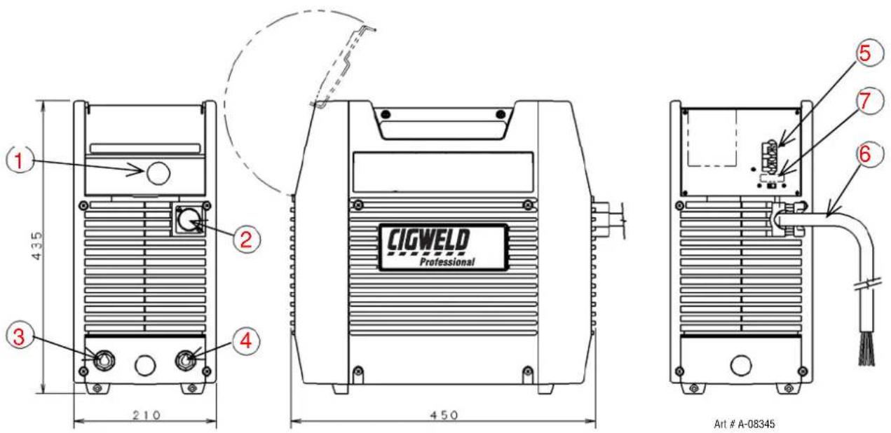
Figure 4 – Transarc 300 Si Power Source
1. Control Knob
This control sets the selected weld parameter, rotating it clockwise increases the parameter that is indicated on the digital meter. Pushing the knob inward displays the actual welding voltage.
2. Remote Control Socket
The 14 pin Remote Control Socket is used to connect remote current control devices to the welding Power Source. To make connections, align keyway, insert plug, and rotate threaded collar fully clockwise.
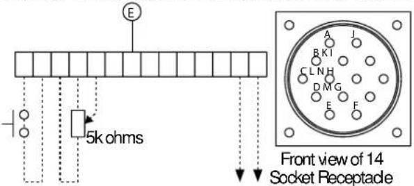
| Socket Pin | Function |
| A | Torch Switch Input (24V) to energize weld current. |
| (connect pins A & B to turn on welding current) | |
| B | Torch Switch Input (0V) to energize weld current |
| (connect pins A & B to turn on welding current) | |
| C | 5k ohm (maximum) connection to 5k ohm remote control potentiometer |
| D | Zero ohm (minimum) connection to 5k ohm remote control potentiometer |
| E | Wiper arm connection to 5k ohm remote control potentiometer |
| G | Mains Earth |
| F,H,I,J,K,L | Not Used |
| M | OK to move current detect signal for robotics applications |
| N | OK to move current detect signal for robotics applications |
3. Positive Terminal
Welding current flows from the Power Source via heavy duty Dinse type terminal. It is essential, however, that the male plug is inserted and turned securely to achieve a sound electrical connection.
4. Negative Terminal
Welding current flows from the Power Source via heavy duty Dinse type terminal. It is essential, however, that the male plug is inserted and turned securely to achieve a sound electrical connection.

CAUTION
Loose welding terminal connections can cause overheating and result in the male plug being fused in the bayonet terminal.
5. ON/OFF Switch
This switch connects the Primary supply voltage to the inverter when in the ON position. This enables the Power Supply.
WARNING
When the welder is connected to the Primary supply voltage, the internal electrical components maybe at primary potential with respect to earth.
6. Input Cable
The input cable connects the Primary supply voltage to the equipment.
7. SMART Logic Switch
Manual slide switch mounted on the back panel selects for proper input voltage. If this slide is not set to the position that matches the input voltage from the electrical source the Smart Logic circuit will inhibit welding power source output. The digital meter will show primary input error code.
NOTE
Due to variations that can occur in manufactured products, claimed performance, voltages, ratings, all capacities, measurements, dimensions and weights quoted are approximate only. Achievable capacities and ratings in use and operation will depend upon correct installation, use, applications, maintenance and service.
4.02 Weld Parameter Description
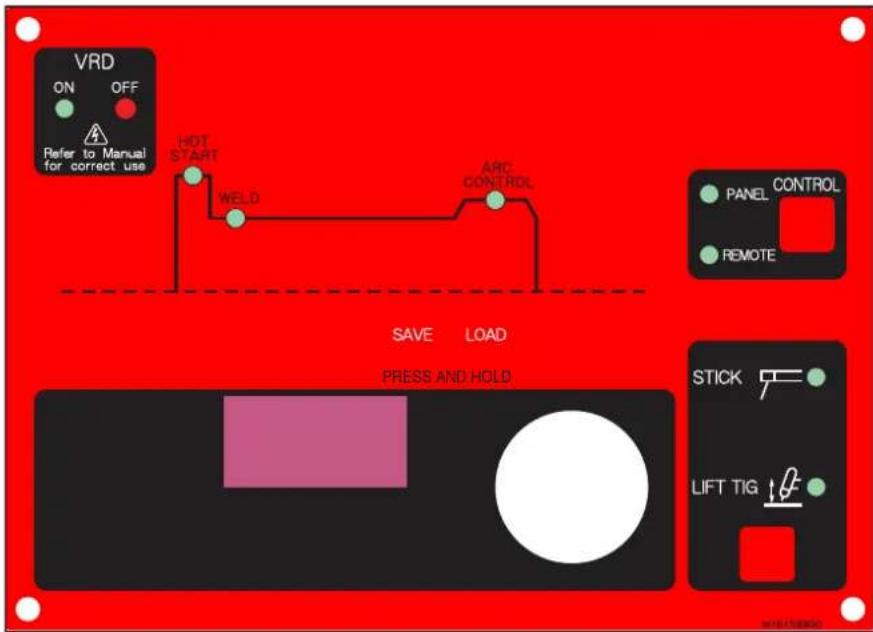
Figure 5 - Transarc 300 Si Front Panel with Parameter Description
| noitpircseD retemara | ||
| HOT START | This parameter operates in STICK weld mode and is used to improve the start characteristics for stick electrodes. e.g. low hydrogen electrodes. It sets the peak start current on top of the (WELD) current. | |
 | Weld Current (Amperage)- sets the STICK and TIG WELD current. | |
 | ARC CONTROL - This parameter provides a suitable short circuit current in STICK welding to improve electrode sticking and arc stability. | |
 | LIFT TIG mode of operation. A remote control device may be used for use during LIFT TIG operation. See section 4.01, section 2 “Remote Control Socket”, for complete details of the remote device. | |
 | STICK Mode of operation | |
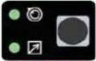 REMOTE REMOTE | Selects Mode of Operation: Panel or Remote | |
 |  | By using the Save & Load buttons, the operator can easily save up to 5 welding parameter programs. |
NOTE
The Save/Load button must remain depressed for 3 seconds in order to store the settings.
Table 3 – Weld Parameter Descriptions
4.03 Weld Parameters for Transarc 300 Si
| Weld Mode | ||||
| Weld Parameter Parameter Range | Factory Setting | Incremental Unit | STICK LIFT TIG | |
| HOT START 0 to 70A 20A 1A Yes No | ||||
| WELD CUR 5 to 300A DC 80A 1A Yes Yes | ||||
| ARC CONTROL 0 to 100% 10% 1% | Yes No | |||
4.04 Power Source Features
| Feature | Description |
| New Digital Control | Almost all welding parameters are adjustable |
| Touch Panel Switches | Touch switches eliminate mechanical damage |
| Front Control Cover | Protects front panel controls |
| Digital Meter | Displays selected weld parameter valueDisplays weld current when weldingDisplays weld current for 20 seconds after weld has been completedA selected weld parameter value can be adjusted at any time even while welding |
| Intelligent Fan Control | The intelligent cooling system is designed to reduce dust and foreign material build-up, whilst providing optimum cooling.Fan speed reduces approximately 30 seconds after machine is turned onFan speed increases when internal components reaches operating temperature |
| ON/OFF switch | Primary voltage Supply ON/OFF switch located on rear panel |
| Voltage Reduction Device (VRD) | Reduces the OCV when the power supply is not in use. Eliminates the need for add on voltage reducers and has no effect on arc starting.VRD fully complies to AS 60974.1When Stick mode is selected the green VRD light is ON when not welding and red when welding.When in TIG modes VRD is off. |
SECTION 5: SET-UP FOR SMAW (STICK) AND GTAW (TIG)
Conventional operating procedures apply when using the Welding Power Source, i.e. connect work lead directly to work piece and electrode lead is used to hold electrode. Wide safety margins provided by the coil design ensure that the Welding Power Source will withstand short-term overload without adverse effects. The welding current range values should be used as a guide only. Current delivered to the arc is dependent on the welding arc voltage, and as welding arc voltage varies between different classes of electrodes, welding current at any one setting would vary according to the type of electrode in use. The operator should use the welding current range values as a guide, then finally adjust the current setting to suit the application.

WARNING
Before connecting the work clamp to the work and inserting the electrode in the electrode holder make sure the Primary power supply is switched off.

CAUTION
Remove any packaging material prior to use. Do not block the air vents at the front or rear or sides of the Welding Power Source.
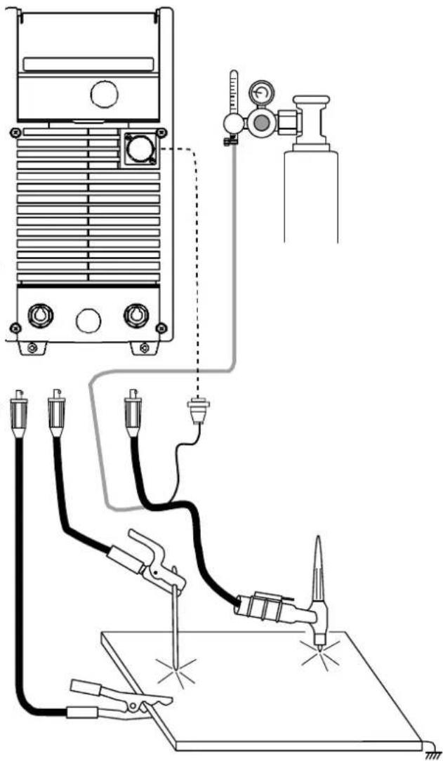
Figure 6 – Transarc 300 Si Set-up
NOTES
NOTE: Scroll Buttons are used to select the parameters to be set. The LED's show which function is being adjusted on the weld sequence graph. Refer to Symbols Table located in the front of the manual for Symbol descriptions.
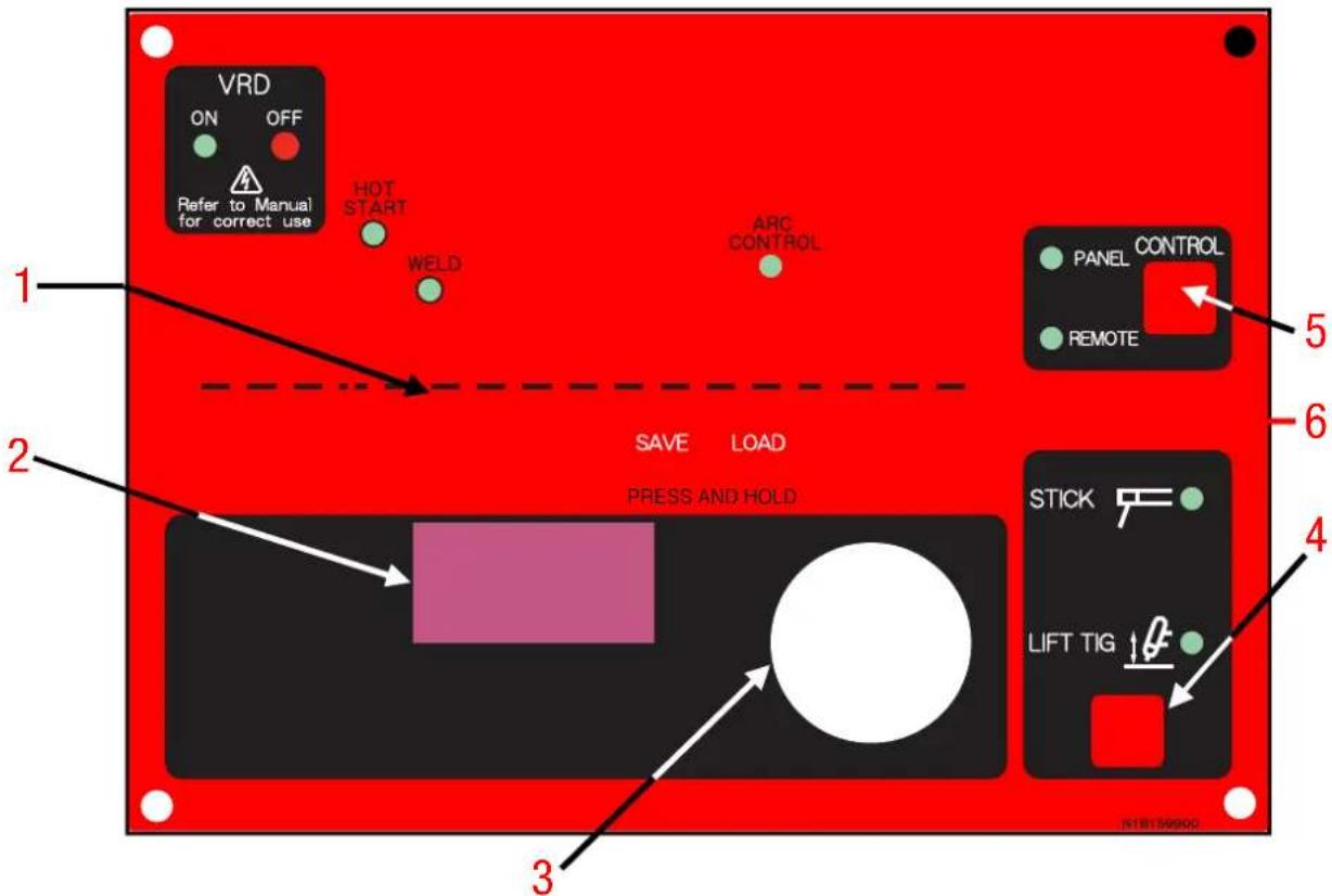
Figure 7 – Transarc 300 Si Front Panel
- Scroll Buttons – used to select the parameter to be set. The LED's show which function is being adjusted on the Sequence Graph.
- Digital LED display – Welding amperage and parameter values are displayed in this window. Internal warnings such as over temperature, low or high input voltage applied are signaled to the operator by a warning sound and error message on the screen.
- Control Knob - allows the operator to adjust the output amperage within the entire range of the power source, also used to set each parameter value.
- Process Button – This button selects between STICK or Lift TIG mode.
- Remote Current Function – Pressing this buttons enables remote current functions.
- Save & Load Buttons – Press and hold these buttons for 3 seconds to save or load up to 5 welding parameter programs.
6.01 Stick Welding
- Connect work lead to negative terminal
- Connect electrode lead to positive terminal
- Switch machine on
- Set Contactor
- Connect remote control device if required
Use the Scroll Buttons to move to the parameter to be set. The LED will show which function is being adjusted on the weld sequence graph. Use the control knob to adjust each parameter.
- Set HOT START
- Set WELD current
- Set Arc Control
Commence welding
6.02 DC LIFT TIG Welding
- Connect work lead to positive terminal
- Connect TIG torch to negative terminal
- Switch machine on
- Set weld current.
- Connect remote control device if desired
Use the Scroll Buttons to move to the parameter to be set. The LED will show which function is being adjusted on the weld sequence graph. Use the control knob to adjust each parameter.
- Set WELD current
Commence welding
SECTION 7:
BASIC TIG WELDING GUIDE
7.01 Electrode Polarity
Connect the TIG torch to the - / TORCH terminal and the work lead to the + / WORK terminal for direct current straight polarity. Direct current straight polarity is the most widely used polarity for DC TIG welding. It allows limited wear of the electrode since 70% of the heat is concentrated at the work piece.
7.02 Tungsten Electrode Current Ranges
| Electrode Diameter DC Current (Amps) | |
| 0.040” (1.0mm) 30 – 60 | |
| 1/16” (1.6mm) 60 – 115 | |
| 3/32” (2.4mm) 100 – 165 | |
| 1/8” (3.2mm) 135 – 200 | |
| 5/32” (4.0mm) 190 – 280 | |
| 3/16” (4.8mm) 250 – 340 |
Table 4 – Current ranges for varies tungsten electrode sizes
7.03 Tungsten Electrode Types
| Electrode Type (Ground Finish) | Welding Application Features Color | Code | |
| Thoriated 2% | DC welding of mild steel, stainless steel and copper. | Excellent arc starting, Long life, High current carrying capacity. | Red |
| Ceriated 2% | DC welding of mild steel, stainless steel, copper, | Longer life, More stable arc, Easier starting, Wider current | Grey |
Table 5 – Tungsten electrode types
7.04 Guide for Selecting Filler Wire Diameter
| Filler Wire Diameter DC Current Range (Amps) | |
| 1/16” (1.6 mm) | 20 - 90 |
| 3/32” (2.4 mm) | 65 - 115 |
| 1/8” (3.2 mm) | 100 - 165 |
| 3/16” (4.8 mm) | 200-350 |
Table 6 – Filler wire selection guide
NOTE
The filler wire diameter specified in Table 6 is a guide only, other diameter wires may be used according to the welding application.
7.05 Shielding Gas Selection
| Alloy Shielding Gas | |
| Aluminium & alloys Argon | |
| Carbon Steel Argon | |
| Stainless Steel Argon | |
| Copper Argon | |
Table 7 – Shielding gas selection
7.06 TIG Welding Parameters for Low Carbon & Low Alloy Steel Pipe
| Electrode Type & Diameter | Current Range DC Amperes | Filler Rod for Root Pass | Joint Preparation |
| Thoriated 2% 3/32” (2.4 mm) | 120 - 170 Yes | ||
| Thoriated 2% 3/32” (2.4 mm) | 100 - 160 Yes | ||
| Thoriated 2% 3/32” (2.4 mm) | 90 - 130 No |
Table 8 – TIG welding parameters for low carbon & low alloy steel pipe
7.07 Welding Parameters for Steel
| Base Metal Thickness | DC Current for Mild Steel | DC Current for Stainless Steel | Tungsten Electrode Diameter | Filler Rod Diameter (if required) | Argon Gas Flow Rate Joint Type | |
| 0.040” 35-45 | 20-30 0.040” | 1/16” Butt/Corner | 5-7 | |||
| 1.0mm | 40-50 | 25-35 | 1.0mm | 1.6mm | Lap/ Fillet | |
| 0.045” 45-55 | 30-45 0.040” | 1/16” Butt/Corner | 5-7 | |||
| 1.2mm | 50-60 | 35-50 | 1.0mm | 1.6mm | Lap/ Fillet | |
| 1/16” | 60-70 | 40-60 | 1/16” | 1/16” | 7 | Butt/Corner |
| 1.6mm | 70-90 | 50-70 | 1.6mm | 1.6mm | Lap/ Fillet | |
| 1/8” | 80-100 | 65-85 | 1/16” | 3/32” | 7 | Butt/Corner |
| 3.2mm | 90-115 | 90-110 | 1.6mm | 2.4mm | Lap/ Fillet | |
| 3/16” | 115-135 | 100-125 | 3/32” | 1/8” | 10 | Butt/Corner |
| 4.8mm | 140-165 | 125-150 | 2.4mm | 3.2mm | Lap/ Fillet | |
| 14 ” | 160-175 | 135-160 | 1/8” | 5/32” | 10 | Butt/Corner |
| 6.4mm | 170-200 | 160-180 | 3.2mm | 4.0mm | Lap/ Fillet |
Table 9 – DC TIG welding parameters
SECTION 8: BASIC ARC WELDING GUIDE
8.01 Electrode Polarity
Stick electrodes are generally connected to the ‘+’ terminal and the work lead to the ‘-’ terminal but if in doubt consult the electrode manufacturers literature.
8.02 Effects of Stick Welding Various Materials
High tensile and alloy steels
The two most prominent effects of welding these steels are the formation of a hardened zone in the weld area, and, if suitable precautions are not taken, the occurrence in this zone of under-bead cracks. Hardened zone and under-bead cracks in the weld area may be reduced by using the correct electrodes, preheating, using higher current settings, using larger electrodes sizes, short runs for larger electrode deposits or tempering in a furnace.
Manganese steels
The effect on manganese steel of slow cooling from high temperatures is to em brittle it. For this reason it is absolutely essential to keep manganese steel cool during welding by quenching after each weld or skip welding to distribute the heat.
Cast Iron
Most types of cast iron, except white iron, are weldable. White iron, because of its extreme brittleness, generally cracks when attempts are made to weld it. Trouble may also be experienced when welding white-heart malleable, due to the porosity caused by gas held in this type of iron.
Copper and alloys
The most important factor is the high rate of heat conductivity of copper, making preheating of heavy sections necessary to give proper fusion of weld and base metal.
Types of Electrodes
Arc Welding electrodes are classified into a number of groups depending on their applications. There are a great number of electrodes used for specialized industrial purposes which are not of particular interest for everyday general work. These include some low hydrogen types for high tensile steel, cellulose types for welding large diameter pipes, etc. The range of electrodes dealt with in this publication will cover the vast majority of applications likely to be encountered; are all easy to use and all will work on even the most basic of welding machines.
| Metals being joined Electrode Comments | ||
| Mild steel 6013 | Ideal electrodes for all general purpose work. Features include out standing operator appeal, easy arc starting and low spatter. | |
| Mild steel 7014 | All positional electrode for use on mild and galvanized steel furniture, plates, fences, gates, pipes and tanks etc. Especially suitable for vertical-down welding. | |
| Cast iron 99% Nickel | Suitable for joining all cast irons except white cast iron. | |
| Stainless steel 318L-16 | High corrosion resistance. Ideal for dairy work, etc. On stainless steels. | |
| Copper, Bronze, Brass, etc. | Bronze5.7 ERCUSI-A | Easy to use electrode for marine fittings, water taps and valves, water trough float arms, etc. Also for joining copper to steel and for bronze overlays on steel shafts. |
| High Alloy Steels, Dissimilar Metals, Crack Resistance. All Hard-To-Weld Jobs. | 312-16 | It will weld most problematical jobs such as springs, shafts, broken joins mild steel to stainless and alloy steels. Not suitable for Aluminum. |
Table 10 - Types of Electrodes
NOTES
SECTION 9: ROUTINE MAINTENANCE
The only routine maintenance required for the power supply is a thorough cleaning and inspection, with the frequency depending on the usage and the operating environment.
WARNING
Disconnect primary power at the source before opening the enclosure. Wait at least two minutes before opening the enclosure to allow the primary capacitors to discharge.
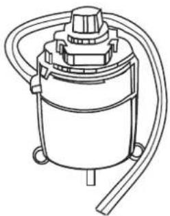
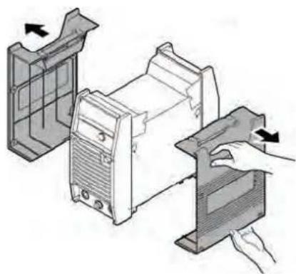
To clean the unit, open the enclosure and use a vacuum cleaner to remove any accumulated dirt and dust. The unit should also be wiped clean, if necessary; with solvents that are recommended for cleaning electrical apparatus.

CAUTION
Do not blow air into the power supply during cleaning. Blowing air into the unit can cause metal particles to interfere with sensitive electrical components and cause damage to the unit.
Warning!
Disconnect input power before maintaining.
Maintain more often if used under severe conditions
Each Use
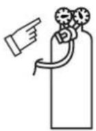
Visual check of regulator and pressure
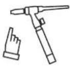
Visual check of torch Consumable parts
Weekly
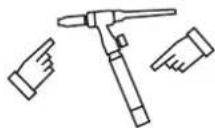
Visually inspect the torch body and consumables
natural_image
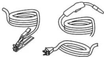
Three types of coiled cable or wire connectors, no text or symbols presentVisually inspect the cables and leads. Replace as needed
3 Months
Replace all broken parts
natural_image
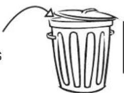
Simple line drawing of a trash bin with an arrow pointing to the top (no text or symbols)Clean exterior of power supply
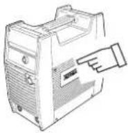
6 Months
natural_image
Line drawing of a vacuum cleaner with coiled tubing and a central top component (no text or symbols)Art # A-07681_AC
Bring the unit to an authorized CIGWELD Service Provider to remove any accumulated dirt and dust from the interior. This may need to be done more frequently under exceptionally dirty conditions.
natural_image
Illustration of a computer monitor with open case and side panel, showing internal components and directional arrows (no text or symbols)SECTION 10: BASIC TROUBLESHOOTING

WARNING
There are extremely dangerous voltages and power levels present inside this product. Do not attempt to open or repair unless you are an Accredited Cigweld™ Service Provider and you have had training in power measurements and troubleshooting techniques.
If major complex subassemblies are faulty, then the Welding Power Source must be returned to an Accredited Cigweld Service Provider for repair.
The basic level of troubleshooting is that which can be performed without special equipment or knowledge.
10.01 TIG Welding Problems
Weld quality is dependent on the selection of the correct consumables, maintenance of equipment and proper welding technique.
| Description Possible Cause Remedy | ||
| 1. Excessive beard build-up or poor penetration or poor fusion at edges of weld. | Welding current is too low Increase weld current and/or faulty joint preparation | |
| 2. Weld bead too wide and flat or undercut at edges of weld or excessive burn through | Welding current is too high Decrease weld current | |
| 3. Weld bead too small or insufficient penetration or ripples in bead are widely spaced apart | Travel speed too fast Reduce travel speed | |
| 4. Weld bead too wide or excessive bead build up or excessive penetration in butt joint | Travel speed too slow Increase travel speed | |
| 5. Uneven leg length in fillet joint Wrong placement of filler rod Re-position filler rod | ||
| 6. Electrode melts when arc is struck. | Electrode is connected to the ‘+’ terminal. | Connect the electrode to the ‘-’ terminal. |
| 7. Dirty weld pool. | A. Electrode contaminated through contact with work piece or filler rod material.B. Gas contaminated with air. | A. Clean the electrode by grinding off the contaminates.B. Check gas lines for cuts and loose fitting or change gas cylinder. |
| 8. Electrode melts or oxidizes when an arc is struck. | A. No gas flowing to welding region.B. Torch is clogged with dust.C. Gas hose is cut.D. Gas passage contains impurities.E. Gas regulator turned off.F. Torch valve is turned off.G. The electrode is too small for the welding current. | A. Check the gas lines for kinks or breaks and gas cylinder contents.B. Clean torchC. Replace gas hose.D. Disconnect gas hose from torch then raise gas pressure and blow out impurities.E. Turn on.F. Turn on.G. Increase electrode diameter or reduce the welding current. |
| 9. Poor weld finish. Inadequate shielding | gas. Increase gas flow or check gas line | for gas flow problems. |
| 10. Arc flutters during TIG welding. A. Tungsten electrode is too large for the welding current.B. Absence of oxides in the weld pool. | A. Select the right size electrode.Refer to Basic TIG Welding guide.B. Refer Basic TIG Welding Guide for ways to reduce arc flutter. | |
| 11. Welding arc can not be established. | A. Work clamp is not connected to the work piece or the work/torch leads are not connected to the right welding terminals.B. Torch lead is disconnected.C. Gas flow incorrectly set, cylinder empty or the torch valve is off. | A. Connect the work clamp to the work piece or connect the work/torch leads to the right welding terminals.B. Connect it to the ‘-’ terminal.C. Select the right flow rate, change cylinders or turn torch valve on. |
| 12. Arc start is not smooth. | A. Tungsten electrode is too large for the welding current.B. The wrong electrode is being used for the welding jobC. Gas flow rate is too high.D. Incorrect shielding gas is being used.E. Poor work clamp connection to work piece. | A. Select the right size electrode.Refer to Section 7, Basic TIG Welding Guide.B. Select the right electrode type.Refer to Section 7, Basic TIG Welding Guide.C. Select the correct rate for the welding job.Refer to Section 7, Basic TIG Welding Guide.D. Select the right shielding gas.Refer to Section 7, Basic TIG Welding Guide.E. Improve connection to work piece. |
10.02 Stick Welding Problems
| Description Possible Cause Remedy | ||
| 1. Gas pockets or voids in weld metal (Porosity). | A. Electrodes are damp.B. Welding current is too high.C. Surface impurities such as oil, grease, paint, etc. | A. Dry electrodes before use.B. Reduce welding current.C. Clean joint before welding. |
| 2. Crack occurring in weld metal soon after solidification commences | A. Rigidity of joint.B. Insufficient throat thickness.C. Cooling rate is too high. | A. Redesign to relieve weld joint of severe stresses or use crack resistance electrodes.B. Travel slightly slower to allow greater build up in throat.C. Preheat plate and cool slowly. |
| 3. A gap is left by failure of the weld metal to fill the root of the weld. | A. Welding current is too low.B. Electrode too large for joint.C. Insufficient gap.D. Incorrect sequence. D. Use correct | A. Increase welding currentB. Use smaller diameter electrode.C. Allow wider gap.build-up sequence. |
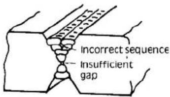
Figure 8 – Example of insufficient gap or incorrect sequence
| 4. Portions of the weld run do not fuse to the surface of the metal or edge of the joint. | A. Small electrodes used on heavy cold plate.B. Welding current is too low.C. Wrong electrode angle.D. Travel speed of electrode is too high.E. Scale or dirt on joint surface. | A. Use larger electrodes and pre-heat the plate.B. Increase welding currentC. Adjust angle so the welding arc is directed more into the base metalD. Reduce travel speed of electrodeE. Clean surface before welding. |
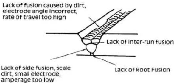
Figure 9 – Example of lack of fusion
TRANSARC 300 Si
| 5. Non-metallic particles are trapped in the weld metal (slag inclusion). | A. Non-metallic particles may be trapped in undercut from previous run.B. Joint preparation too restricted. B. Allow for adequate penetration and room for cleaning out the slag.C. Irregular deposits allow slag to be trapped.D. Lack of penetration with slag trapped beneath weld bead.E. Rust or mill scale is preventing full fusion.F. Wrong electrode for position in which welding is done. | A. If bad undercut is present, clean slag out and cover with a run from a smaller diameter electrode.C. If very bad, chip or grind out irregularities.D. Use smaller electrode with sufficient current to give adequate penetration. Use suitable tools to remove all slag from corners.E. Clean joint before welding.F. Use electrodes designed for position in which welding is done, otherwise proper control of slag is difficult. |
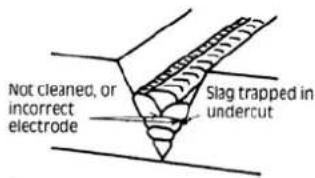
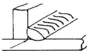
natural_image
Simple line drawing of a tool interacting with a surface (no text or symbols)Figure 10 – Examples of slag inclusion
10.03 Power Source Problems
| Description | Possible Cause | Remedy |
| 1. The welding arc cannot be established | A. The Primary supply voltage has not been switched ON.B. The Welding Power Source switch is switched OFF.C. Loose connections internally. | A. Switch ON the Primary supply voltage.B. Switch ON the Welding Power Source.C. Have an Accredited Cigweld Service Provider repair the connection. |
| 2. Maximum output welding current can not be achieved with nominal Mains supply voltage. | Defective control circuit | Have an Accredited Cigweld Service Provider inspect then repair the welder. |
| 3. Welding current reduces when welding | Poor work lead connection to the work piece. | Ensure that the work lead has a positive electrical connection to the work piece. |
| 4. No gas flow when the torch trigger switch is depressed. | A. Gas hose is cut.B. Gas passage contains impurities.C. Gas regulator turned off.D. Torch trigger switch lead is disconnected or switch/cable is faulty. | A. Replace gas hose.B. Disconnect gas hose from the rear of Power Source then raise gas pressure and blow out impurities.C. Turn gas regulator on.D. Reconnect lead or repair faulty switch/cable. |
SECTION 11: VOLTAGE REDUCTION DEVICE (VRD)
11.01 VRD Specification
| Description Transarc | 300 Si | Notes |
| VRD Open Circuit Voltage 15.3 to 19.8V Open circuit voltage between welding terminals | ||
| VRD Resistance 148 to 193 ohms | The required resistance between welding terminals to turn ON the welding power | |
| VRD Turn OFF Time 0.2 to 0.3 seconds | The time taken to turn OFF the welding power once the welding current has stopped | |
11.02 VRD Maintenance
Routine inspection and testing (power source)
An inspection of the power source, an insulation resistance test and an earth resistance test shall be carried out.
a) For transportable equipment, at least once every 3 months; and
b) For fixed equipment, at least once every 12 months.
The owners of the equipment shall keep a suitable record of the periodic tests.
NOTE
A transportable power source is any equipment that is not permanently connected and fixed in the position in which it is operated.
In addition to the above tests and specifically in relation to the VRD fitted to this machine, the following periodic tests should also be conducted by an accredited Cigweld Service Provider.
| Description | Required Parameters |
| VRD Open Circuit Voltage | Less than 20V; at Vin=415V |
| VRD Turn ON Resistance | Less than 200 ohms |
| VRD Turn OFF Time | Less than 0.3 seconds |
If this equipment is used in a hazardous location or environments with a high risk of electrocution then the above tests should be carried out prior to entering this location.
NOTES
SECTION 12: POWER SOURCE ERROR CODES
| Description Possible Cause Remedy Remarks | |||
| 1 E01 error code displayed.Temperature sensor TH1 (protects IGBTs) is greater than 80°C for about 1 second. | A The Welding Power Source's duty cycle has been exceeded.B Fan ceases to operate. B Have an Accredited Cigweld Service Provider investigate.C Air flow is restricted by vents being blocked. | A Let Power Source cool down then keep within its duty cycle. | Weld current ceases. Buzzer sounds constantly.E01 resets when TH1 decreases to 70°C for about 30 seconds. |
| 2 E02 error code displayed.Temperature sensor TH2 (protects IGBTs) is greater than 90°C for about 1 second. | A The Welding Power Source's duty cycle has been exceeded.B Fan ceases to operate. B Have an Accredited Cigweld Service Provider investigate.C Air flow is restricted by vents being blocked. | A Let Power Source cool down then keep within its duty cycle. | Weld current ceases. Buzzer sounds constantly.E02 resets when TH2 decreases to 70°C for about 30 seconds. |
| 3 E03 error code displayed.Primary (input) current too high. | A Primary current too high because welding arc is too longB Mains supply voltage is more than 10% below nominal voltage | A Reduce length of welding arcB Have an Accredited Cigweld Service Provider or a qualified electrician check for low Mains voltage. | Weld current ceases. Buzzer sounds constantly.Switch machine off then on to reset E03 error. |
| 4 E11 error code displayed.Over Primary supply (input) voltage at primary capacitors is exceeded for one second. | Primary supply voltage is greater than the nominal voltage plus 10%. | Have an Accredited Cigweld Service Provider or a qualified electrician check the Primary voltage. | Weld current ceases. Buzzer sounds constantly.Error code E11 automatically will reset when the voltage reduces. |
| 5 E12 error code displayed.Under mains supply (input) voltage warning primary capacitors is reduced for one second. | Mains supply voltage is down to a dangerously low level. | Have an Accredited Cigweld Service Provider or a qualified electrician check the Mains voltage. Have an Accredited Cigweld Service Provider or a qualified electrician check the primary cable & fuses. | Weld current ceases. Buzzer sounds constantly.Error code E12 will automatically reset when the voltage increases. |
| Description Possible Cause Remedy Remarks | |||
| 6 E14 error code displayed. Under mains supply (input) voltage warning primary capacitors is reduced for one second. | Mains supply voltage is less than the nominal operating voltage plus 10%. | Have an Accredited Cigweld Service Provider or a qualified electrician check the Mains voltage. | Weld current available. Buzzer sounds intermittently. Error code E14 will automatically reset when the voltage increases. |
| 7 E81 error code displayed. Wrong Primary supply (input) voltage connected. | When 3 phase machine is first turned on with the wrong Primary supply (input) voltage connected. | Have an Accredited Cigweld Service Provider check the Mains voltage. | No weld current is available. Buzzer sounds constantly. Switch machine off. |
| 8 E82 error code displayed. Link switch plug not connected. | Link switch plug not connected. | Have an Accredited Cigweld Service Provider or a qualified electrician check the connector plug on input PCB. | No weld current is available. Buzzer sounds constantly. Switch machine off. |
| 9 E83 error code displayed. CPU checks mains supply (input) voltage when the on/off switch on rear panel of machine is turned ON. | The Primary supply (input) voltage fluctuates and is not stable. | Have an Accredited Cigweld Service Provider or a qualified electrician check the connector plug on the input PCB and the Mains voltage. | No weld current is available. Buzzer sounds constantly. Switch machine off then on to reset E83 error. |
| 10 E93 error code displayed. Memory chip (EEPROM) on control PCB can not read/write weld parameters. | Memory chip (EEPROM) error. | Have an Accredited Cigweld Service Provider or a qualified electrician check the control PCB. | Weld current is ceases. Buzzer sounds constantly. Switch machine off. |
| 11 E94 error code displayed. Temperature sensor TH1 for IGBTs is an open circuit. | The Welding Power Source's temperature sensors have malfunctioned. | Have an Accredited Cigweld Service Provider check or replace the temperature sensors. | Weld current ceases. Buzzer sounds constantly. Switch machine off. |
| 12 E99 error code displayed. Mains supply (input) voltage has been turned off, but control circuit has power from the primary capacitors. | A Main on/off switch on machine has been turned off.B Mains supply (input) voltage has been turned off. | A Turn on/off switch on.B Have an Accredited Cigweld Service Provider or a qualified electrician check the Main voltage and fuses. | Weld current ceases. Buzzer sounds constantly. Must switch machine off then on to reset E99 error. |
APPENDIX 1: TRANSARC 300 Si ACCESSORIES
| Description Part No. Details | ||
| 17 Series air cooled TIG torch (suitable for TransTig 200Pi) | 518710402 TIG | torch with 4 metre cable & remote current control |
| 26 Series air cooled TIG torch 53872 | 0401 TIG torch w | with 4 metre cable & remote current control |
| 200 Amp lead set, 5 metre | 646323 | 1 x 5m work lead; 1 x 5m electrode holder |
| 400 Amp lead set, 8 metre | 646325 | 1 x 8m work lead; 1 x 8m electrode holder |
| Slide controller | OTD 10/4013 | 200Pi, 200AC/DC slider only |
| OTD 10/2004 | 300Pi, 300AC/DC, 400i slider only | |
| Hand pendant | OTD 10/4014 | 200Pi, 200AC/DC hand pendant only |
| OTD 10/2005 | 300Pi, 300AC/DC, 400i hand pendant only | |
| Foot controller | OTD 10/4016 | 200Pi, 200AC/DC |
| OTD 10/2007 | 300Pi, 300AC/DC, 400i | |
| CIGWELD COMET argon regulator | 301527 | Regulator only |
| CIGWELD COMET argon flowmeter 0-15 lpm 301710 Flowmeter only | ||
| CIGWELD COMET argon flowmeter 10-40 lpm 301711 Flowmeter only | ||
| CIGWELD COMET argon regulator/flowmeter | 301526 | Regulator/flowmeter only |
| VAF-4 Wirefeeder (for 400i ONLY) | 705700 | VAF-4 wirefeeder, 8m interconnection, operating manual |
| VS212 Voltage sensing wirefeeder | W3512006 | VS212 wirefeeder, operating manual |
| Tweco® 4 MIG Torch | 717201 | MIG torch with 3.6m cable, T4 connection |
| ArcMaster Pro Auto-darkening Helmet, 9-13 - blue | 454294 Welding | helmet, 2 x spare cover lenses, product bag, operating manual |
| ArcMaster Pro Auto-darkening Helmet, 9-13 - blue with graphic | 454295 Welding | helmet, 2 x spare cover lenses, product bag, operating manual |
| ArcMaster Pro Auto-darkening Helmet, 9-13 - black with graphic | 454296 | Welding helmet, 2 x spare cover lenses, product bag, operating manual |
APPENDIX B: TRANSARC 300 Si INTERCONNECT DIAGRAM
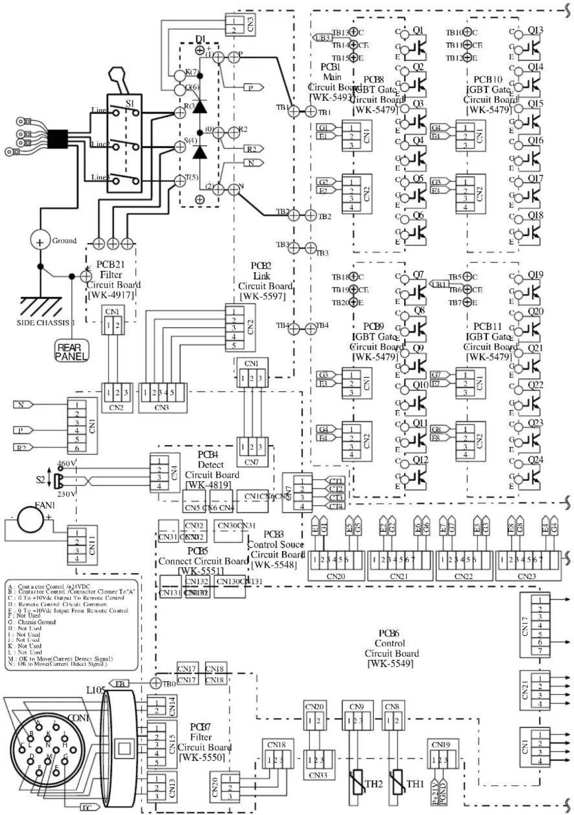
flowchart
graph TD
    A["Power Supply"] --> B["Circuit Board"]
    B --> C["PCB10"]
    B --> D["PCB21"]
    B --> E["PCB3"]
    B --> F["PCB4"]
    B --> G["PCB5"]
    B --> H["PCB6"]
    B --> I["Ground"]

    subgraph Power Supply
        J["CN1"] --> K["CN2"]
        L["CN3"] --> M["CN4"]
        N["CN4"] --> O["CN5"]
        P["CN5"] --> Q["CN6"]
        R["CN6"] --> S["CN7"]
        T["CN7"] --> U["CN8"]
        V["CN8"] --> W["CN9"]
        X["CN9"] --> Y["CN10"]
        Z["CN10"] --> AA["CN11"]
        AB["CN11"] --> AC["CN12"]
        AD["CN12"] --> AE["CN13"]
        AF["CN13"] --> AG["CN14"]
        AH["CN14"] --> AI["CN15"]
        AJ["CN15"] --> AK["CN16"]
        AL["CN16"] --> AM["CN17"]
        AN["CN17"] --> AO["CN18"]
        AP["CN18"] --> AQ["CN19"]
        AR["CN19"] --> AS["CN20"]
        AT["CN20"] --> AU["CN21"]
        AV["CN21"] --> AW["CN22"]
        AX["CN22"] --> AY["CN23"]
    end

    subgraph Control
        AZ["PCB6"] --> BA["Circuit Board"]
        BB["Circuit Board"] --> BC["TW-55-49"]
        BD["Circuit Board"] --> BE["TW-54-79"]
        BF["Circuit Board"] --> BG["TW-54-79"]
        BH["Circuit Board"] --> BI["TW-54-79"]
    end

    subgraph Power Supply
        BJ["PCB7"] --> BK["Circuit Board"]
        BL["Circuit Board"] --> BL["TW-55-48"]
        BM["Circuit Board"] --> BM["TW-54-79"]
        BN["Circuit Board"] --> BN["TW-54-79"]
        BO["Circuit Board"] --> BO["TW-54-79"]
    end

    subgraph Power Supply
        BP["CN3"] --> BQ["CN4"]
        BR["CN4"] --> BS["CN5"]
        BT["CN5"] --> BU["CN6"]
        BV["CN6"] --> BW["CN7"]
        BX["CN7"] --> BY["CN8"]
        BZ["CN8"] --> CA["CN9"]
        CB["CN9"] --> DA["CN10"]
    end

    subgraph Control
        DB["CN10"] --> DC["CN11"]
        DV["CN11"] --> DW["CN12"]
    end

    subgraph Power Supply
        DO["CN10"] --> DP["CN11"]
        DP["CN11"] --> DR["CN12"]
    end

    subgraph Power Supply
        EQ["CN10"] --> RQ["CN11"]
        SB["CN11"] --> TX["CN12"]
    end

    subgraph Control
        DU["CN10"] --> DV["CN11"]
        DW["CN11"] --> BX["CN12"]
    end

    subgraph Power Supply
        DU["CN10"] --> DV["CN11"]
    end

    subgraph Power Supply
        DU["CN10"] --> DV["CN11"]
    end

    subgraph Control
        DU["CN10"] --> DV["CN11"]
    end

    subgraph Power Supply
        DU["CN10"] --> DV["CN11"]
    end

    subgraph Control
        DU["CN10"] --> DV["CN11"]
    end

    subgraph Power Supply
        DU["CN10"] --> DV["CN11"]
    end

    subgraph Power Supply
        DU["CN10"] --> DV["CN11"]
    end

    subgraph Control
        DU["CN10"] --> DV["CN11"]
    end

    subgraph Power Supply
        DU["CN10"] --> DV["CN11"]
    end

    subgraph Control
![PCB14 TRANS Board [WK-5594] TB7 TB2 TB8 UB2 UB16 UB22 TB1 CT3 CT2 L1 TB35 TB33 TB34 TB30 TB32 TB31 D5 D7 D2 D4 FCH1 SH.DET- TO1+Output Terminal HCT1 RY+15V RY_ON CN1 CN3 PCB20 Filter Circuit Board [WK-5499] SIDE CHASSIS 3 Ground TO2-Output Terminal FRONT PANEL EB Ground SIDE CHASSIS 2 R2 UB2UB1 R3 UB4UB3 PCB12 Panel Circuit Board [WK-5527] PCB13 Encoder Board [WK-5528] CN1 CN2 CN1 CN1 CN1 CN1 CN1 CN1 CN1 CN1 CN1 CN1 CN1 CN1 CN1 CN1 CN1 CN1 CN1 CN1 CN1 CN1 CN1 CN1 CN1 CN1 CN1 CN1 CN1 CN1 CN1 CN1 CN1 CN1 CN1 CN1](/content/2026/05/942189/images/f9ed29404bea6317573d3db434ebb515a7473c0cfbe8385fdc8feddbec30f47d.jpg)
LIMITED WARRANTY: CIGWELD, A Thermadyne Company, hereafter, “CIGWELD” warrants to customers of its authorized distributors hereafter “Purchaser” that its products will be free of defects in workmanship or material. Should any failure to conform to this warranty appear within the time period applicable to the CIGWELD products as stated below, CIGWELD shall, upon notification thereof and substantiation that the product has been stored, installed, operated, and maintained in accordance with CIGWELD’s specifications, instructions, recommendations and recognized standard industry practice, and not subject to misuse, repair, neglect, alteration, or accident, correct such defects by suitable repair or replacement, at CIGWELD’s sole option, of any components or parts of the product determined by CIGWELD to be defective.
CIGWELD MAKES NO OTHER WARRANTY, EXPRESS OR IMPLIED. THIS WARRANTY IS EXCLUSIVE AND IN LIEU OF ALL OTHERS, INCLUDING, BUT NOT LIMITED TO ANY WARRANTY OF MERCHANTABILITY OR FITNESS FOR ANY PARTICULAR PURPOSE.
LIMITATION OF LIABILITY: CIGWELD SHALL NOT UNDER ANY CIRCUMSTANCES BE LIABLE FOR SPECIAL, INDIRECT OR CONSEQUENTIAL DAMAGES, SUCH AS, BUT NOT LIMITED TO, LOST PROFITS AND BUSINESS INTERRUPTION. The remedies of the Purchaser set forth herein are exclusive and the liability of CIGWELD with respect to any contract, or anything done in connection therewith such as the performance or breach thereof, or from the manufacture, sale, delivery, resale, or use of any goods covered by or furnished by CIGWELD whether arising out of contract, negligence, strict tort, or under any warranty, or otherwise, shall not, except as expressly provided herein, exceed the price of the goods upon which such liability is based. No employee, agent, or representative of CIGWELD is authorized to change this warranty in any way or grant any other warranty.
PURCHASER'S RIGHTS UNDER THIS WARRANTY ARE VOID IF REPLACEMENT PARTS OR ACCESSORIES ARE USED WHICH IN CIGWELD'S SOLE JUDGEMENT MAY IMPAIR THE SAFETY OR PERFORMANCE OF ANY CIGWELD PRODUCT. PURCHASER'S RIGHTS UNDER THIS WARRANTY ARE VOID IF THE PRODUCT IS SOLD TO PURCHASER BY NON-AUTHORIZED PERSONS.
The warranty is effective for the time stated below beginning on the date that the authorized distributor delivers the products to the Purchaser. Notwithstanding the foregoing, in no event shall the warranty period extend more than the time stated plus one year from the date CIGWELD delivered the product to the authorized distributor.
-
The Trade Practices Act 1974 (Commonwealth) and similar State Territory legislation relating to the supply of goods and services, protects consumers' interests by ensuring that consumers are entitled in certain situations to the benefit of various conditions, warranties, guarantees, rights and remedies (including warranties as to merchantability and fitness for purpose) associated with the supply of goods and services. A consumer should seek legal advice as to the nature and extent of these protected interests. In some circumstances, the supplier of goods and services may legally stipulate that the said conditions, warranties, guarantees, rights and remedies are limited or entirely excluded. The warranties set out in Clause 2 shall be additional to any nonexcludable warranties to which the Customer may be entitled pursuant to any statute.
-
Subject to Clause 3. CIGWELD gives the following warranties to the Customer:
Insofar as they are manufactured or imported by CIGWELD, goods will upon delivery be of merchantable quality and reasonably fit for the purpose for which they are supplied by CIGWELD.
CIGWELD will repair or, at its option, replace those of the goods which, upon examination, are found by CIGWELD to be defective in workmanship and/or materials.
CIGWELD reserves the right to request documented evidence of date of purchase.
- The Warranty in Clause 2;
Is conditional upon:
The Customer notifying CIGWELD or our Accredited Distributor in writing of its claim within seven (7) days of becoming aware of the basis thereof, and at its own expense returning the goods which are the subject of the claim to CIGWELD or nominated Accredited Distributor/Accredited Service Provider. The goods being used in accordance with the Manufacturer's Operating Manuals, and under competent supervision.
Does not apply to:
Obsolete goods sold at auction, second-hand goods and prototype goods.
Breakdown or malfunction caused by accident, misuse or normal wear and tear.
Repairs or replacement made other than by CIGWELD or Accredited Service Providers, unless by prior arrangement with CIGWELD.
Replacement parts or accessories which may affect product safety or performance and which are not manufactured, distributed or approved by CIGWELD.
- CIGWELD declares that, to the extent permitted by law, it hereby limits its liability in respect of the supply of goods which are not of a kind ordinarily acquired for personal, domestic or household use or consumption to any one or more of the following (the choice of which shall be at the option of CIGWELD).
The replacement of the goods or the supply of equivalent goods.
The repair of goods.
The payment of cost of replacing the goods or acquiring equivalent goods.
The payment of the cost of having goods repaired.
- Except as provided in Clauses 2 to 4 above, to the extent permitted by statute, CIGWELD hereby excludes all liability for any loss, damage, death or injury of any kind whatsoever occasioned to the Customer in respect of the supply of goods including direct, indirect, consequential or incidental loss, damage or injury of any kind.
These warranty periods relate to the warranty conditions in clause 2. All warranty periods are from date of sale from the Accredited Distributor of the equipment. Notwithstanding the foregoing, in no event shall the warranty period extend more than the time stated plus one year from the date CIGWELD delivered the product to the Accredited Distributor. Unless otherwise stated the warranty period includes parts and labour. CIGWELD reserves the right to request documented evidence of date of purchase.
MULTI PROCESS EQUIPMENT WARRANTY PERIOD
| CIGWELD PROFESSIONAL INVERTER WELDING EQUIPMENT | WARRANTY PERIOD | LABOR |
| Transtig 200 Pi, Transtig 200 AC/DC, Transarc 300 Si, Transtig 300 Pi, Transtig 300 AC/DC, Transmig 400 i | ||
| Original Main Power Magnetics...... | 3 years | 2 years |
| Original Main Power Rectifiers, Control P.C. Boards, power switch semiconductors...... | 2 years | 2 years |
| All other circuits and components including, but not limited to, relays, switches, contactors, solenoids, fans, electric motors...... | 1 year | 1 year |
Please note that the information detailed in this statement supersedes any prior published data produced by CIGWELD.
GLOBAL CUSTOMER SERVICE CONTACT INFORMATION
Cigweld, Australia
71 Gower Street
Preston, Victoria
Australia, 3072
Telephone: 61-3-9474-7400
Fax: 61-3-9474-7510
Email: cigweldsales@cigweld.com.au
Thermadyne, China
RM 102A
685 Ding Xi Rd
Chang Ning District
Shanghai, PR, 200052
Telephone: 86-21-69171135
Fax: 86-21-69171139
Thermadyne USA
2800 Airport Road
Denton, Tx 76207 USA
Telephone: (940) 566-2000
800-426-1888
Fax: 800-535-0557
Email: sales@thermalarc.com
Thermadyne Asia Sdn Bhd
Lot 151, Jalan Industri 3/5A
Rawang Integrated Industrial Park - Jln Batu Arang
48000 Rawang Selangor Darul Ehsan
West Malaysia
Telephone: 603+ 6092 2988
Fax:603+60921085
Thermadyne Canada
2070 Wyecroft Road
Oakville, Ontario
Canada, L6L5V6
Telephone: (905)-827-1111
Fax: 905-827-3648
Thermadyne Italy
OCIM, S.r.L.
Via Benaco, 3
20098 S. Giuliano
Milan, Italy
Tel: (39) 02-98 80320
Fax: (39) 02-98 281773
Thermadyne Europe
Europe Building
Chorley North Industrial Park
Chorley, Lancashire
England, PR6 7Bx
Telephone: 44-1257-261755
Fax: 44-1257-224800
Thermadyne International
2070 Wyecroft Road
Oakville, Ontario
Canada, L6L5V6
Telephone: (905)-827-9777
Fax: 905-827-9797
- Manual
- WE APPRECIATE YOUR BUSINESS!
- YOU ARE IN GOOD COMPANY!
- The Brand of Choice for Contractors and Fabricators Worldwide.
- Record the following information for Warranty purposes:
- Table of Contents
- SECTION 1:
- SAFETY INSTRUCTIONS AND WARNINGS .... 1-1
- SECTION 2:
- INTRODUCTION AND DESCRIPTION 2-1
- SECTION 3:
- INSTALLATION RECOMMENDATIONS 3-1
- SECTION 4:
- OPERATOR CONTROLS 4-1
- SECTION 5:
- SET-UP FOR SMAW (STICK) AND GTAW (TIG) 5-1
- SECTION 6:
- SECTION 7:
- SECTION 8:
- SECTION 9:
- SECTION 10:
- SECTION 11:
- SECTION 12:
- SECTION 1: SAFETY INSTRUCTIONS AND WARNINGS
- Arc Welding Hazards
- ELECTRIC SHOCK can kill.
- TRANSARC 300 Si
- WARNING
- NOTE
- ABOUT PACEMAKERS:
- Principal Safety Standards
- DECLARATION OF CONFORMITY
- NOTES
- SECTION 2: INTRODUCTION AND DESCRIPTION
- How To Use This Manual
- Equipment Identification
- Receipt Of Equipment
- Symbol Chart
- Description
- Functional Block Diagrams
- Transporting Methods
- SECTION 3: INSTALLATION RECOMMENDATIONS
- Environment
- Location
- Electrical Input Connections
- DO NOT TOUCH live electrical parts.
- • Electrical Input Requirements
- Mains Supply Voltage Requirements
- 415V Mains Current Circuit Requirements for the Transarc 300 Si
- • High Frequency Introduction
- Explosives
- Computers
- • High Frequency Interference
- Direct Radiation
- Transmission via the Supply Lead
- Radiation from Welding Leads
- Re-radiation from Unearthed Metallic Objects
- Specifications
- Duty Cycle
- OPERATOR CONTROLS
- Transarc 300 Si Controls
- Control Knob
- Remote Control Socket
- Positive Terminal
- Negative Terminal
- CAUTION
- ON/OFF Switch
- Input Cable
- SMART Logic Switch
- Weld Parameter Description
- Weld Parameters for Transarc 300 Si
- Power Source Features
- SECTION 5: SET-UP FOR SMAW (STICK) AND GTAW (TIG)
- Stick Welding
- DC LIFT TIG Welding
- BASIC TIG WELDING GUIDE
- Electrode Polarity
- Tungsten Electrode Current Ranges
- Tungsten Electrode Types
- Guide for Selecting Filler Wire Diameter
- Shielding Gas Selection
- TIG Welding Parameters for Low Carbon & Low Alloy Steel Pipe
- Welding Parameters for Steel
- SECTION 8: BASIC ARC WELDING GUIDE
- Electrode Polarity
- Effects of Stick Welding Various Materials
- High tensile and alloy steels
- Manganese steels
- Cast Iron
- Copper and alloys
- Types of Electrodes
- SECTION 9: ROUTINE MAINTENANCE
- Warning!
- Disconnect input power before maintaining.
- SECTION 10: BASIC TROUBLESHOOTING
- TIG Welding Problems
- Stick Welding Problems
- Power Source Problems
- SECTION 11: VOLTAGE REDUCTION DEVICE (VRD)
- VRD Specification
- VRD Maintenance
- APPENDIX B: TRANSARC 300 Si INTERCONNECT DIAGRAM
- GLOBAL CUSTOMER SERVICE CONTACT INFORMATION
- Cigweld, Australia
- Thermadyne, China
- Thermadyne USA
- Thermadyne Asia Sdn Bhd
- Thermadyne Canada
- Thermadyne Italy
- Thermadyne Europe
- Thermadyne International
Brand : Cigweld
Model : Transarc 300i
Category : Welding machine