
AT100-PA - Professional audio equipment ATLAS - Free user manual and instructions
Find the device manual for free AT100-PA ATLAS in PDF.


User questions about AT100-PA ATLAS
0 question about this device. Answer the ones you know or ask your own.
Ask a new question about this device
Download the instructions for your Professional audio equipment in PDF format for free! Find your manual AT100-PA - ATLAS and take your electronic device back in hand. On this page are published all the documents necessary for the use of your device. AT100-PA by ATLAS.
USER MANUAL AT100-PA ATLAS
Attenuator Installations
Wiring
Each terminal will hold up to 2-16AWG stranded wire. For larger wires or home run situations, a small length of wire and a wire nut are recommended. Attach wire according to label on terminal block as shown to the right (Non-PA Models will not have the "VDC+" and "VDC-" terminals).
*Install the unit with the terminal block on top. This will ensure that the OFF position is in the bottom.
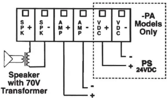
(-PA) PRIORITY ATTENUATORS
Schematics for Priority Attenuators Power Switching Req. for -PA Attenuators

flowchart
graph TD
    A["TO RELAY POWER"] --> B["BLACK"]
    A --> C["WHITE"]
    A --> D["BLUE"]
    B --> E["ATTENUATOR"]
    C --> E
    D --> E
    E --> F["GREEN"]
    G["TO AMP OUTPUT"] --> H["RED"]
    I["LEARN"] --> J["LEARN OUT"]
    K["LEARN OUT"] --> L["LEARN OUT"]
Wiring Requirements: (1) Pair for Audio, (1) Pair for Relay

Use 2nd external relay when paging switch is part of a paging microphone. This will reduce hum and noise pickup from the mic.
Relay Specifications:
Coil Voltage: 24 VDC Coil Current: 10MA
Contacts: SPDT-2Amp Rating
Relay has a protective cover.
(-RM) Rack Mount
Drill holes in panel using the template to the right. Peel off adhesive backing on escutcheon overlay. Align hole openings with holes in panel and affix to surface. Remove knob and nut from attenuator. Insert bushing through large hole in panel making sure that the small indentation on the bracket lines up with the small hole in the panel. Fasten attenuator to panel with the nut. Fit attenuator knob on shaft. Tighten screw on knob to secure.

Dimensional Specifications
-RM Models supplied without a faceplate. All other models supplied with a single faceplate. Double gang stainless steel faceplate can be ordered separately.
| Model A B C | |||
| AT10 2 | ^1/_8" (54mm) 2 | ^3/_4" (70mm) 1 | ^3/_4" (45mm) |
| AT35 2 | ^1/_8" (54mm) 2 | ^3/_4" (70mm) 1 | ^3/_4" (45mm) |
| AT100 2 | ^1/_2" (64mm) 2 | ^3/_4" (70mm) 1 | ^3/_4" (45mm) |


Brand : ATLAS
Model : AT100-PA
Category : Professional audio equipment