
DFS-900M - Video switch SONY - Free user manual and instructions
Find the device manual for free DFS-900M SONY in PDF.


| Product Type | Multi Format Video Switcher |
| Brand | Sony |
| Model | DFS-900M |
| Supported Video Formats | SD: 480i/59.94, 576i/50; HD: 1080i/59.94, 1080i/50, 720p/59.94, 720p/50 |
| Standard Inputs | 8x SDI |
| Standard Outputs | 4x SDI (PGM1, PGM2, AUX1, AUX2) |
| Maximum Inputs (with options) | 24x SDI or analog/DVI |
| Maximum Outputs (with options) | 12x SDI or analog/DVI |
| Internal DME Channels | 2 standard, up to 8 with optional BKDF-940 boards |
| Keyers | 6 (4 full-function keys + 2 downstream keys) |
| Control Panel Options | BKDF-901 (1M/E) or BKDF-902 (1.5M/E) |
| Power Requirements (Processor) | 100-240 V AC, 50/60 Hz, 250 W max |
| Dimensions (Processor Unit) | 424 x 132.5 x 460 mm (16.7 x 5.2 x 18.1 in) |
| Weight (Processor Unit) | Approx. 8.5 kg (18.7 lb) |
| Operating Temperature | 5 to 40 °C (41 to 104 °F) |
| Optional Expansion Boards | BKDF-910 (4x SDI in), BKDF-911 (2x SD analog in), BKDF-912 (2x DVI in), BKDF-960 (4x SDI out), BKDF-961 (2x SD analog out), BKDF-962 (2x DVI out), BKDF-940 (2CH DME), BKDF-950 (Multi Viewer), BKDF-990 (Redundant PSU) |
| Cleaning | Use a soft dry cloth; do not use liquid cleaners or solvents. |
| Safety Precautions | Must be earthed; do not expose to rain or moisture; refer servicing to qualified personnel; use approved power cord. |
| Repairability and Spare Parts | Contact Sony authorized service centers; optional boards and power supply unit available. |
| Software Version | 2.1 (manual covers versions up to 2.1) |
Frequently Asked Questions - DFS-900M SONY
User questions about DFS-900M SONY
0 question about this device. Answer the ones you know or ask your own.
Ask a new question about this device
Download the instructions for your Video switch in PDF format for free! Find your manual DFS-900M - SONY and take your electronic device back in hand. On this page are published all the documents necessary for the use of your device. DFS-900M by SONY.
USER MANUAL DFS-900M SONY
For Customer in China
Multi Format Switcher
出版日期:2011年8月
Printed on recycled paper. http://www.sony.net/
Primed in Japan
Operating Instructions
Software Version 2.1
Before operating the unit, please read this manual thoroughly and retain it for future reference.
DFS-900M
© 2010 Sony Corporation

Owner's Record
The model and serial numbers are located on the bottom. Record these numbers in the spaces provided below. Refer to these numbers whenever you call upon your Sony dealer regarding this product.
Model No. ____ Serial No. ____
WARNING
To reduce the risk of fire or electric shock, do not expose this apparatus to rain or moisture.
To avoid electrical shock, do not open the cabinet. Refer servicing to qualified personnel only.
THIS APPARATUS MUST BE EARTHED.
For the customers in the U.S.A.
This equipment has been tested and found to comply with the limits for a Class A digital device, pursuant to Part 15 of the FCC Rules. These limits are designed to provide reasonable protection against harmful interference when the equipment is operated in a commercial environment. This equipment generates, uses, and can radiate radio frequency energy and, if not installed and used in accordance with the instruction manual, may cause harmful interference to radio communications. Operation of this equipment in a residential area is likely to cause harmful interference in which case the user will be required to correct the interference at his own expense.
You are cautioned that any changes or modifications not expressly approved in this manual could void your authority to operate this equipment.
All interface cables used to connect peripherals must be shielded in order to comply with the limits for a digital device pursuant to Subpart B of Part 15 of FCC Rules.
This device complies with Part 15 of the FCC Rules. Operation is subject to the following two conditions: (1) this device may not cause harmful interference, and (2) this device must accept any interference received, including interference that may cause undesired operation.
For the customers in Canada
This Class A digital apparatus complies with Canadian ICES-003.

This symbol is intended to alert the user to the presence of important operating and maintenance (servicing) instructions in the literature accompanying the appliance.
WARNING: THIS WARNING IS APPLICABLE FOR USA ONLY.
If used in USA, use the UL LISTED power cord specified below.
DO NOT USE ANY OTHER POWER CORD.
Plug Cap Parallel blade with ground pin
(NEMA 5-15P Configuration)
Cord Type SJT, three 16 or 18 AWG wires
Length Minimum 1.5m (4 ft .11in.),
Less than 2.5 m (8 ft .3 in.)
Rating Minimum 10A, 125V
Using this unit at a voltage other than 120V may require the use of a different line cord or attachment plug, or both. To reduce the risk of fire or electric shock, refer servicing to qualified service personnel.
WARNING: THIS WARNING IS APPLICABLE FOR OTHER COUNTRIES.
-
Use the approved Power Cord (3-core mains lead) / Appliance Connector / Plug with earthing-contacts that conforms to the safety regulations of each country if applicable.
-
Use the Power Cord (3-core mains lead) / Appliance Connector / Plug conforming to the proper ratings (Voltage, Ampere).
If you have questions on the use of the above Power Cord / Appliance Connector / Plug, please consult a qualified service personnel.
IMPORTANT (for BKDF-901/902)
The nameplate is located on the bottom.
For the customers in Europe
This product with the CE marking complies with the EMC Directive issued by the Commission of the European Community.
Compliance with this directive implies conformity to the following European standards:
• EN55103-1 : Electromagnetic Interference(Emission)
• EN55103-2 : Electromagnetic Susceptibility(Immunity)
This product is intended for use in the following Electromagnetic Environment: E4 (controlled EMC environment, ex. TV studio).
The manufacturer of this product is Sony Corporation, 1-7-1 Konan, Minato-ku, Tokyo, Japan.
The Authorized Representative for EMC and product safety is Sony Deutschland GmbH, Hedelfinger Strasse 61, 70327 Stuttgart, Germany. For any service or guarantee matters please refer to the addresses given in separate service or guarantee documents.
This apparatus shall not be used in the residential area.
For the customers in Europe, Australia and New Zealand
WARNING
This is a Class A product. In a domestic environment, this product may cause radio interference in which case the user may be required to take adequate measures.
For kundene i Norge
Dette utstyret kan kobles til et IT-strømfordelingssystem.
For DFS-900M
Attention-when the product is installed in Rack:
- Prevention against overloading of branch circuit When this product is installed in a rack and is supplied power from an outlet on the rack, please make sure that the rack does not overload the supply circuit.
- Providing protective earth When this product is installed in a rack and is supplied power from an outlet on the rack, please confirm that the outlet is provided with a suitable protective earth connection.
- Internal air ambient temperature of the rack When this product is installed in a rack, please make sure that the internal air ambient temperature of the rack is within the specified limit of this product.
- Prevention against achieving hazardous condition due to uneven mechanical loading When this product is installed in a rack, please make sure that the rack does not achieve hazardous condition due to uneven mechanical loading.
- Install the equipment while taking the operating temperature of the equipment into consideration For the operating temperature of the equipment, refer to the specifications of the Operation Manual.
- When performing the installation, keep the following space away from walls in order to obtain proper exhaust and radiation of heat.
Right, Left : 10 cm (4 inches) or more
Rear : 10 cm (4 inched) or more
For BKDF-901/902
When installing the installation space must be secured in consideration of the ventilation and service operation.
- Do not block the ventilation slots at the left side and right side panels, and vents of the fans.
- Leave a space around the unit for ventilation.
- Leave more than 10cm of space in the rear of the unit to secure the operation area.
When the unit is installed on the desk or the like, leave at least 10 cm of space in the left and right sides. Leaving 10 cm or more of space above the unit is recommended for service operation.
AVERTISSEMENT
Features of This System ....11
Functions Newly Supported in Version 2.0 ...... 12
Functions Newly Supported in Version 2.1 ...... 12
Chapter 2 Names and Functions of Parts
BKDF-901 1M/E Control Panel....13
BKDF-901 Operating Blocks.... 13
1 External Connections and Power Block.... 14
2 KEYER Block 14
3 KEY DELEGATION Block.... 15
4 Cross-Point Bus Block 15
5 Transition Block 15
6 Joystick Block 16
7 Numeric Keypad.... 17
8 DME/SETUP Block 18
9 Display Panel/Menu Control Block.... 19
BKDF-901 Rear Panel.... 19
BKDF-902 1.5M/E Control Panel....21
BKDF-902 Operating Blocks.... 21
1 External Connections and Power Block 22
2 KEYER Block 22
3 Key/AUX (Auxiliary) Bus Control Block.... 22
4 M/E Cross-Point Bus Block 23
5 PROGRAM/PRESET Cross-Point Bus Block 23
6 PROGRAM/PRESET Transition Block.... 24
7 DSK (Downstream Key)/Fade to Black Control Block 24
8 M/E Transition Block 25
9 DME/SETUP Block 25
10 Joystick Block 26
11 Numeric Keypad.... 26
12 Display Panel/Menu Control Block.... 26
BKDF-902 Rear Panel.... 26
DFS-900M Processor Unit....28
Front Panel 28
Rear Panel.... 28
Options 31
BKDF-910 4 SDI Input Board 31
BKDF-911 2 SD Video Input Board.... 31
BKDF-912 2 DVI Input Board.... 31
BKDF-960 4 SDI Output Board.... 31
BKDF-961 2 SD Video Output Board 31
BKDF-962 2 DVI Output Board 32
BKDF-990 Power Supply Unit 32
Other Options 32
Chapter 3 Preparations
Connecting Peripheral Devices....33
Connection Example 1: Live Recording / Playout System...... 33
Connection Example 2: System with Editor Connected 35
Connection Example 3: Connection to a Device Equipped with a DVI (DVI-I) Connector .... 37
Installing Optional Expansion Boards....39
Installing I/O Expansion Boards 39
Installing Function Expansion Boards 46
Installing the BKDF-990 Power Supply Unit 51
Connecting Up the Switcher....54
Changing the Internal Switch Setting in the Processor Unit (When Using the BKDF-902) 54
Connecting the Processor Unit and the Control Panel 57
Powering the System On 58
Menu Operations 63
Basic Menu Configuration 63
Displaying Menus.... 63
Operating in Menus 64
Menu Operations in the GUI Menus 64
Basic Switcher Settings....71
Setting the Video Format 71
Making Input and Output Reference Sync Signal Settings.... 73
Making Settings Related to Input Signals 74
Making Settings Related to Output Signals 89
Making Other Settings.... 104
Chapter 4 Basic Operations
Selecting Backgrounds....108
Switching Backgrounds....109
Cutting to a New Background 109
Cutting by using GPI output.... 111
Using Transitions to Switch to the Next Video (Mix and Wipe)..... 111
Switching with Mix Transitions.... 113
Switching with Wipe and DME Wipe Transitions.... 115
Setting Transition Rates 117
Using Color Mattes....117
Assigning Color Mattes to Cross-Point Selection Buttons ...... 117
Changing the Colors of Color Mattes.... 117
Using Color Mattes in Background Transitions.... 118
Using Internally Stored Still Images ....118
Acquiring Still Image Files 118
Using Stored Still Images in Background Transitions 120
Using 32-bit TGA Still Image Files in Keys.... 120
Writing Still Images to USB Flash Drives 121
Deleting Still Image Files.... 121
Using Keys to Compose Video....122
Setting Up Keys.... 122
Inserting Keys by a Cut Transition.... 126
Inserting Keys by a Mix Transition.... 127
Inserting Keys by a Wipe or DME Wipe Transition.... 127
Changing Key Priorities 128
Applying DME Effects to Keys 129
Inserting Downstream Keys (with a Cut).... 129
Inserting Downstream Keys (with a Mix).... 130
Using Fade to Black ....131
Chapter 5 Adjusting Wipes and Keys
Customizing Wipe Patterns ....132
Adding Borders to Wipe Patterns.... 132
Modifying Wipe Patterns 133
Registering User Patterns 133
Customizing DME Effects ....134
Changing the Position, Shape, and Size of Images 134
Adding Borders to Images.... 137
Adding Trail Effects, and Changing the Color Type 139
Adjusting 3D DME Warp Effects .... 140
Adding Lighting Effects.... 146
Registering User Patterns 147
Applying Masks to Keys ....147
Adding Edges to Keys....148
Masking Downstream Keys with Box Masks ....150
Chapter 6 Registering Operations and Settings
Event Operations....151
Registering Events.... 151
Recalling Events.... 152
Deleting Events 155
Sequence Operations....156
Creating Sequences 156
Recalling Sequences.... 156
Playing Sequences.... 158
Editing Sequences 159
Deleting Sequences 160
Chapter 7 External Control Interface Settings
Serial Interface Settings....161
Communications Protocol Settings 162
Baud Rate Settings 162
Parity Bit Settings.... 162
GPI Input Settings....163
Tally Output Settings....164
GPI Output Settings....166
Chapter 8 Other Operations and Settings
Backing Up Data ....167
Backing Up, Restoring, and Clearing All Data 168
Backing Up, Restoring, and Clearing System Data 168
Backing Up, Restoring, and Clearing File Data.... 168
Updating the System....169
Status Information....170
To display the Status sub menus 170
Option Board Information 171
Software Version Information.... 171
Alarms 171
Chapter 9 3D Mode
Overview....172
I/O of 3D Mode Signals....172
3D Mode Signal Assignments ......173
System Settings....174
Switching to 3D Mode 174
Selecting the 2D/3D Mode of Stored Still Images.... 174
3D Mode Operations....175
Appendix
Menu Structure ....176
Transition Menu (for Transition, Wipe, and DME Settings) ...... 176
Keyer Menu (for Key Settings) 177
Still Store Menu (for Still Image Settings).... 179
Sequence Event Menu (for Sequence and Event Registration)...... 179
Setup Menu (for System Settings).... 180
DME Menu (for DME Settings).... 183
Pattern List....189
Wipe 189
Mask 191
DME Wipe 192
Messages and Actions to Take 197
Updating the Software....202
Checking the Software Versions 202
Preparing for Software Update.... 202
Updating the Software.... 202
Performing Update Confirmation, Data Clear, and Data Restoration203
Troubleshooting 205
Problems during Startup.... 205
Problems on Video Input and Output.... 205
Problems on Functions 206
Specifications 207
DFS-900M Processor Unit 207
BKDF-901 1M/E Control Panel....207
BKDF-902 1.5M/E Control Panel.... 208
Optional Products 208
Pin Assignments.... 211
Example Connection of GPI Input 214
Example Connection of Tally/GPI Output.... 214
External Dimensions ......215
Glossary ....218
Index 219
Features of This System
The DFS-900M Multi Format Video Switcher is a compact switcher incorporating Digital Multi Effects (DME) functionality, and supporting both SD and HD systems.
Multi-format support
The system supports 480i/59.94 and 576i/50 formats for an SD system, and 1080i/59.94, 1080i/50, 720p/59.94, and 720p/50 formats for an HD system. You can change the format selection with a simple menu operation.
Extensible inputs and outputs
Along with the standard equipment of SDI inputs and outputs (8 inputs, 4 outputs), the following inputs and outputs are available when optional expansion boards are installed.
- SDI inputs and outputs (four channels): BKDF-910/BKDF-960 (of the four channels, two channels provided with format converter)
- SD analog inputs and outputs (two channels): BKDF-911/BKDF-961
• DVI inputs and outputs (two channels): BKDF-912/BKDF-962
For details, see "Installing Optional Expansion Boards" (page 39)
Advanced special effects
As standard features, the system provides two DME channels and six keyers: four full-function keyers and two simple downstream keyers (DSKs). A further maximum of six optional DME channels enables warp and other visual effects.
Multi-view function
The optional multi-view function allows the system to display multiple video images on a single monitor, by splitting the screen into 4, 10, or 16 images. Using the maximum of two multi-view channels, all input video (24 channels) and program/preview output can be viewed simultaneously on just two monitors.
Simple operations in GUI menu screens
You can connect a PC monitor and USB mouse to make system settings in GUI menus.

You can also connect a commercially available touch panel monitor. This allows you to select menu items simply by touching the panel, making it much more convenient to change system settings and adjust setting values.
Compact and easy-to-use control panels
Two types of highly compact and easy-to-use control panels are available, each one designed to meet the requirements of space-limited applications. Together with the 3RU processor chassis, they are ideal for use in any situation where space is at a premium.
The BKDF-902 1.5 M/E Control Panel has a built-in redundant power supply as a standard feature, and allows you to select AUX outputs with key operations.
Functions Newly Supported in Version 2.0
| Functions See | ||
| Input and output of SD analog signals | BKDF-911 board (for input)BKDF-961 board (for output) | Chapters 2 and 3 |
| DVI input and output BKDF- | 912 board (for input)BKDF-962 board (for output) | Chapters 2 and 3 |
| 3D mode Chapter 9 | ||
| Turning ancillary data output on or off Chapter 3 | ||
| GPI output setting Chapter 7 | ||
Functions Newly Supported in Version 2.1
| Functions See | ||
| Customizing DME effects and settings | Selecting global axis Chapter 5 | |
| Trail Settings | ||
| 3D DME warp effects (Ripple, Swirl, Mosaic, Slats, Lens, Mirror) | ||
| Lighting Effects | ||
| Adding Effect Patterns (No.100 to 184, 242 to 251) Appendix | ||
| Description for operation of updating software Appendix | ||
| Troubleshooting Appendix | ||
Names and Functions of Parts
Chapter
2
BKDF-901 1M/E Control Panel
BKDF-901 Operating Blocks
This section explains the functions of control panel parts by dividing them into nine blocks, as shown below.
For details, see the pages indicated within parentheses.
For information about the rear panel of the control panel, see "BKDF-901 Rear Panel" (page 19).

1 External Connections and Power Block
This block provides a connector for USB flash drives, buttons to turn control by editors and GPI on and off, and a button to start the shutdown process.
③GPI button

flowchart
graph TD
    A["② EDITOR button"] --> B["① USB MEMORY connector"]
    B --> C["USB MEMORY"]
    B --> D["EDITOR"]
    B --> E["GP1"]
    B --> F["SHUTDOWN"]
    B --> G["④ SHUTDOWN button"]
①USB MEMORY connector (Type-A)
Use to connect a USB flash drive.
Note
The USB flash drive must be formatted with the FAT16 or FAT32 file system.
② EDITOR button
Turns editor control on and off. When this button is on, you can control the switcher from an editor. When you turn this button on by pressing it twice in quick succession, the Serial menu for setup operations appears in the display panel.
③GPI button
Turns GPI control on and off. When this button is on, you can perform GPI control of the switcher. When you turn this button on by pressing it twice in quick succession, the GPIO Tally menu appears in the display panel.
④SHUTDOWN (start shutdown process) button
When you press this button, lighting it, the message "Shutdown? F2:OK F3:CANCEL" appears. Press the F2 knob to start data backup. When data backup finishes, you can power the switcher off by using the POWER switch on the rear panel of the control panel.
2 KEYER Block
This block allows you to select a key type, to add a mask or edge (shadow) to a key, and to enable or disable DME. The operation target key must be selected in advance (see page 15).
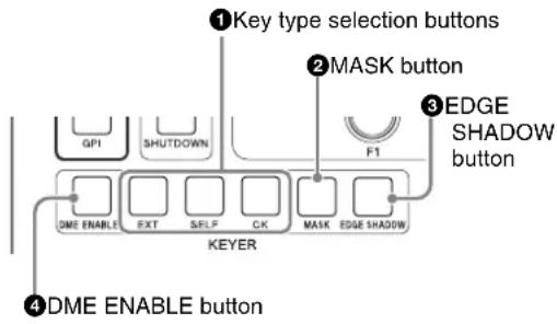
①Key type selection buttons
Press one of the following buttons, lighting it, to select a key type.
EXT (external key) button: Press to create a key by using separate signals for the key fill and key source.
SELF (self key) button: Press to create a key by using the same signal for the key fill and key source.
CK (chroma key) button: Press to create a chroma key.
②MASK button
Press this button, turning it on, to apply a mask to a key. When one of KEY1 to KEY4 is selected as the operation target, the Key Mask sub menu appears when you press this button. This menu allows you to select the mask pattern and to specify the center position and size of the mask.
When DSK1 or DSK2 is selected as the operation target, the Box Mask sub menu appears when you press this button. This menu allows you to specify a box mask position.
③EDGE SHADOW button
Press this button, turning it on, to add an edge or shadow to the key. When you press this button with one of KEY1 to KEY4 selected, the Edge Type sub menu appears, allowing you to select the edge or shadow type, and to specify the width and the color.
④DME ENABLE (enable/disable digital multi effects) button
Enables or disables DME for each of the BKGD (background) and KEY1 to KEY4 layers. This button functions as a three-step switch. With each press, the DME enable/disable state changes as follows, starting with the button not lit (DME disabled).
First press: DME is enabled. As the key, use a white signal for the entire screen.

Second press: With DME still enabled, use a
key-processed signal as the key.

Third press: The button goes out, and DME is disabled again.
3 KEY DELEGATION Block
This block allows you to select KEY1 to KEY4, DSK1, or DSK2 as the target of key, mask, and other operations.
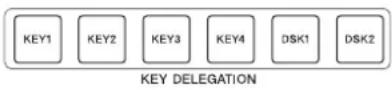
When you press one of the buttons in this block, it selects the corresponding key as the operation target.
The pressed button lights in green and all of the other buttons go out.
If you press a button while it is lit in green, all of the buttons go out and key is not selected as the operation target.
The selection made here specifies the target of operations with buttons in the following blocks.
- KEYER block
- DME settings buttons and USER button in the DME/SETUP block.
- AUTO CK, WIPE POS, DME POS, and DME ROT buttons in the joystick block.
Selections made with these buttons are linked to menu operations. Operations with the buttons may cause a menu to appear, and operations in the menu may cause the buttons to light or go out.
4 Cross-Point Bus Block
This block allows you to select material signals to use in creating the video.

①PROGRAM selection button row
These buttons select current on-air background video.
For the functions of the various buttons, see “Assigning video input signals to cross-point selection buttons” (page 76).
②PRESET selection button row
These buttons select the video that will be the on-air background after a transition.
The signals that are assigned to the buttons in this row are the same as the signals that are assigned to the buttons in the PROGRAM selection button row.
About the SHIFT buttons
The SHIFT buttons on the right side of the PROGRAM and PRESET selection button rows allow you to switch between the two signals assigned to each button in the rows.
The SHIFT buttons have two operating modes: one in which the buttons function as shift buttons only while held down, and one in which the shift function is alternately enabled and disabled each time the buttons are pressed.
For details, see “Selecting the operating mode of the SHIFT buttons” (page 105).
5 Transition Block
This block allows you to set up and execute transitions.

flowchart
graph TD
    A["⑥FTB button"] --> B["①TRANS PVW button"]
    B --> C["⑧Key priorities block"]
    C --> D["⑦Transition range and direction buttons"]
    D --> E["KEY LAYER"]
    E --> F["1 2 3 4 HIGH"]
    F --> G["1 2 3 4"]
    G --> H["1 2 3 4 LOW"]
    H --> I["PRIORITY"]
    I --> J["FADER LIMIT"]
    J --> K["NOR/REV"]
    K --> L["REVERSE"]
    L --> M["DIRECTION"]
    M --> N["FTB"]
    O["④Transition execution block"] --> P["③Transition type selection buttons"]
    P --> Q["②Next transition selection buttons"]
    Q --> R["⑤DSK transition buttons"]
    R --> S["CUT"]
    S --> T["AUTO TRANS"]
    T --> U["MIX"]
    U --> V["Wipe (FAM)"]
    V --> W["DME (NAM)"]
    W --> X["KEY3"]
    X --> Y["KEY4"]
①TRANS PVW (transition preview) button
Allows you to check the video of a transition before carrying out the transition.
When you press this button, lighting it, and then execute a transition with the fader lever, the video of the transition is output to the preview screen.
Notes
- A transition preview is not output when you execute the transition by using an AUTO TRANS button.
- A transition preview is not output when you execute a DME wipe.
②Next transition selection buttons
Select the layer (BKGD, KEY1 to KEY4) to be used in a transition. You can select multiple layers. Pressed buttons light in orange. When a key is turned on, the Key On indicators (red) above the KEY1 to KEY4 buttons light. When DME effects are set for a layer, the DME indicator (green) above that layer lights.
③ Transition type selection buttons
MIX button: Press this button, lighting it, to select a mix transition. The Rate menu appears in the display panel, allowing you to specify the transition rate.
WIPE (FAM (full additive mix)) button: Press this button, lighting it, to select a wipe transition. The Wipe Pattern menu appears in the display panel, allowing you to select the wipe pattern. To select FAM, press this button while pressing the MIX button. Both buttons light.
DME (NAM (non-additive mix)) button: Press this button, lighting it, to use DME in a transition. The DME Pattern menu appears in the display panel, allowing you to select a DME wipe pattern. To select NAM, press this button while pressing the MIX button. Both buttons light.
④ Transition execution block
CUT button: Executes a cut transition. The current video changes instantly to the next video.
AUTO TRANS (auto transition) button: Executes an automatic transition. The video changes according to the currently specified transition rate.
Fader lever: Allows you to control a transition manually. The video changes according to the position of the fader lever as you move it up and down. You can limit the effective range of the fader lever, so that the transition is ended before you move it all the way to the top or bottom.
For information about how to limit the range, see “Limiting the effective range of the fader lever” (page 113).
⑤DSK (downstream key) transition buttons
DSK1 ON and DSK2 ON buttons: Instantly inserts or deletes a downstream key. The button is turned on when a downstream key is inserted.
AUTO TRANS (auto transition) button: Executes a transition using a downstream key.
⑥FTB (fade to black) button
Executes a transition in which the video changes to black. The transition rate is specified by a special fade-to-black setting.
⑦ Transition range and direction buttons
FADER LIMIT button: Limits the effective range of the fader lever. The range limitation is enabled when this button is pressed, lighting it. When you press the button twice to turn it on, the Fader Limit menu appears in the display panel. This menu allows you to specify the effective range of the fader lever as a percentage value. When you press the SHIFT button at the right side of the DME/SETUP block, the effective range is limited to the current fader lever position.
NOR/REV (normal/reverse) button: Press this button, lighting it, to reverse the direction of the transition each time a transition is executed.
REVERSE button: Press this button, lighting it, to execute a transition in the reverse direction.
⑧Key priorities block
This block allows you to change the priorities of the four keys.
For information about how to change the priorities, see “Changing Key Priorities” (page 128).
6 Joystick Block
This block allows you to make settings related to positions on the screen.
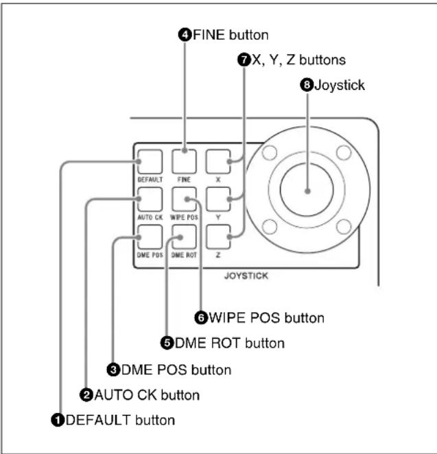
①DEFAULT button
Returns the setting values of parameters assigned to the joystick to the default values.
② AUTO CK (auto chroma key) button
Initiates and confirms the creation of an auto chroma key. Pressing this button once selects auto chroma key mode, in which you can select the color you want to use as the key color to cut out the foreground. Pressing it again confirms the creation of the auto chroma key and returns to manual adjustment mode (the CK Manual 1 menu appears in the display panel).
This button is enabled only when one of KEY1 to KEY4 is selected (see page 15).
For more information about how to create auto chroma keys, see "To create an auto chroma key" (page 123).
③DME POS (DME image position) button
Displays the menu that allows you to specify the position of a DME image. To specify the position of a DME image with the joystick, press this button to display the menu and then adjust the position with the joystick.
④FINE (fine adjustment) button
Selects fine adjustments to setting values when the joystick is moved. Press this button, lighting it, when you want to modify a setting value in small steps.
⑤DME ROT (DME rotation angle) button
Displays the menu that allows you to specify the rotation angle of a DME image. You can adjust the angle with the joystick.
⑥ WIPE POS (wipe center position) button
Displays the menu that allows you to specify the center position of a wipe pattern. To specify the center position with the joystick, press this button to display the menu and then adjust the position with the joystick.
This button is enabled only when key is not selected as the operation target (see page 15).
⑦X, Y, Z (parameter selection) buttons
Select parameters to adjust with the joystick. You can move the joystick to adjust the parameter selected by the lit button.
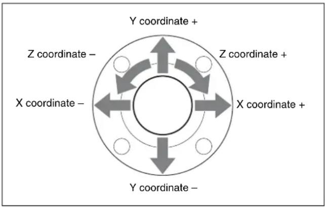
⑧Joystick
As shown in the figure below, you can change X, Y, and Z coordinate parameters by moving the joystick left, right, up and down, or by rotating it to the left or right.
7 Numeric Keypad
The numeric keypad allows you to enter parameter values in menu operations.
When the current parameter has a settable value, you can press the corresponding knob F1 to F4 to enable direct input of a numeric value. Enter the value with the numeric buttons (0 to 9) and then press the ENTER button to confirm it. Press the CANCEL button to cancel the entry operation.
The buttons in the numeric keypad can also be used to switch between menu mode, event mode, and sequence mode, and to perform other operations according to the current mode.

Buttons used to enter numeric values and symbols
| Button display Function | |
| 0 to 9 Enter numeric values. | |
| . Enters a decimal point (.). | |
| - Enters a minus sign (-). | |
| CANCEL Cancels | numeric input. |
| ENTER Confirms | numeric input. |
Buttons used when the MENU button is lit (menu mode)
| Button display Function | |
| ◀◀ Switches to the previous menu. | |
| ▷▷ Switches to the next menu. | |
| EVENT Switches to event mode. | |
| SEQ Switches to sequence mode. | |
| ◀ Switches to the previous sub menu. | |
| ▷ Switches to the next sub menu. |
Buttons used when the EVENT button is lit (event mode)
| Button display Function | |
| EVENT Exits event | mode and switches to menu mode. |
| STORE Stores an event. | |
| RECALL Recalls an event. | |
| INSERT Specifies | settings to be recalled in event mode. |
Buttons used when the SEQ button is lit (sequence mode)
| Button display Function | |
| SEQ Exits sequence mode and switches to menu mode. | |
| STORE Stores a sequence. | |
| ■ Pauses play of a sequence, or restarts play. | |
| LOOP Specifies loop play as the play mode of a sequence. | |
| DIR Reverses the direction of play. | |
| RECALL | Recalls a sequence. |
| ▶■ | Starts play of a sequence, or stops play. |
| NEW | Clears sequence memory. |
| DELETE | Deletes a sequence or key frame. |
| INSERT Inserts a key frame. | |
| ◀, ▷ | Moves the current key frame. |
| ◀◀, ▷◀ | Switches the sequence menu. |
8 DME/SETUP Block
This block provides buttons for use in DME setting and setup operations.
When the SHIFT button on the right side is not lit, the buttons function as DME setting buttons (top-side indications on the buttons). When the SHIFT button is lit, the buttons function as setup buttons (bottom-side indications on the buttons).

flowchart
graph TD
    A["① DME setting buttons"] --> B["② Setup buttons"]
    B --> C["AUX"]
    B --> D["BASIC MATTE"]
    D --> E["BORDER INPUT"]
    E --> F["SUB EFF MV"]
    F --> G["WARP SYSTEM"]
    G --> H["LIGHT STATUS"]
    H --> I["USER STILL"]
    I --> J["SHIFT"]
    K["③ USER/STILL button"] --> L["④ SHIFT button"]
①DME setting buttons
BASIC (basic DME settings) button: Displays a menu that allows you to make basic settings for DME images, such as position and rotation angle.
BORDER button: Displays a menu that allows you to set the color, width, softness and other attributes of borders added to DME images.
SUB EFF (sub effect) button: Displays a menu that allows you to add a Chroma Control sub effect to a DME image.
WARP button: Displays a menu that allows you to set up various warp patterns that can be applied by DME. After the menu appears, each press of the WARP button switches to the next pattern that can be set up.
LIGHT (light source) button: Displays a menu that allows you to specify and adjust light source effects added to 3D effects.
② Setup buttons
AUX (auxiliary) button: Displays an AUX bus output menu that allows you to select the source, format, and level of output signals.
MATTE button: When pressed with the SHIFT button lit, displays a menu that allows you to select the luminance, saturation, and hue of internally generated color matte signals.
INPUT button: When pressed with the SHIFT button lit, displays a menu that allows you to make settings related to input signals, for example make settings for assigning input signals to a bus.
MV (multi-view) button: When pressed with the SHIFT button lit, displays a menu that allows you to select the number of child windows in the optional multi-view display and to select the signals to assign to each child window.
SYSTEM button: When pressed with the SHIFT button lit, displays a menu that allows you to make system settings, such as the video format, the system delay, and the date and time.
STATUS button: When pressed with the SHIFT button lit, displays a menu that allows you to check status information such as the installed option boards, the firmware version, and alarms.
③ USER/ STILL button
When pressed with the SHIFT button unlit, displays the menu used for management of user specified wipe patterns and DME wipe patterns. When pressed with the SHIFT button lit, displays the menu for still image storage operations, such as download, capture, and export.
④SHIFT button
Enables the functions of the STILL button and the setup buttons (except for the AUX button).
9 Display Panel/Menu Control Block

①Display panel
Displays the operation and setting menus of the switcher. The menu title appears in the upper left. Below it is the
display area for four parameters. Useful supporting information for menu operations may appear in the upper right.
②F1 to F4 knobs
The F1 to F4 adjustment knobs are located beneath the parameter display area. They correspond to up to four parameters per menu. You can set parameter values by rotating the knobs or by pressing a knob and entering the value for the corresponding parameter in the numeric keypad.
Instead of specifying parameter values, some menu items may select actions such as store or delete. To execute an action, press the corresponding knob and hold it down for one second or longer.

BKDF-901 Rear Panel

①EXT DISPLAY (external display) connector (high-density D-sub 15-pin)
You can also connect an optional touch panel monitor.
②PROCESSOR connector (RJ-45)
Use the supplied control cable to connect to the PANEL connector of the processor unit.
Note
This connector is for connection to the DFS-900M processor unit only. It cannot be connected to the processor unit of any other system.
CAUTION
- When you connect the PROCESSOR connector of the unit to peripheral devices, use a shielded-type cable to prevent malfunction due to radiation noise.
- For safety, do not connect the connector for peripheral device wiring that might have excessive voltage to this port. Follow the instructions for this port.
ATTENTION
Provided for inspection / maintenance. Not used for operating this system.
④DEVICE connector (USB Type-A)
Allows you to connect an optional touch panel monitor or a mouse.
⑤ Ground terminal
Connect to the system ground wire.
⑥\~ AC IN connector
Connect to an AC power with an AC power cord (not supplied).
⑦ POWER switch
Powers the control panel on and off.
BKDF-902 1.5M/E Control Panel
BKDF-902 Operating Blocks
This section explains the functions of control panel parts by dividing them into twelve blocks, as shown below. For details, see the pages indicated within parentheses.
For information about the rear panel of the control panel, see "BKDF-902 Rear Panel" (page 26).

1 External Connections and Power Block
See descriptions for the BKDF-901 in "1 External Connections and Power Block" (page 14).
2 KEYER Block
See descriptions for the BKDF-901 in "2 KEYER Block" (page 14).
3 Key/AUX (Auxiliary) Bus Control Block

flowchart
graph TD
    A["①Key delegation buttons"] --> B["KEYT"]
    A --> C["KEY2"]
    A --> D["KEY3"]
    A --> E["KEY4"]
    A --> F["DISK1"]
    A --> G["DISK2"]
    H["②AUX delegation buttons"] --> I["AUX1"]
    H --> J["AUX2"]
    H --> K["AUX3"]
    H --> L["AUX4"]
    H --> M["AUX5"]
    H --> N["AUX6"]
    H --> O["AUX7"]
    H --> P["AUX8"]
    H --> Q["AUX9"]
    H --> R["AUX10"]
    S["③KEY/AUX bus selection buttons"] --> T["MV1 K OUT"]
    S --> U["MV2 CLR"]
    S --> V["KEY SRC"]
    W["④Output selection buttons"] --> X["M/E M/E FW"]
    W --> Y["PGM PVW"]
    W --> Z["SHIFT"]
    AA["⑤SHIFT button"] --> AB["SHIFT"]
①Key delegation buttons
See descriptions for the BKDF-901 in "3 KEY DELEGATION Block" (page 15).
② AUX (Auxiliary) delegation buttons
Select the AUX bus output (AUX1 to AUX10) to which one of the KEY/AUX bus selection buttons or of the output selection buttons (MV1/K OUT, KEY SRC) is assigned. Signals selected with the KEY/AUX bus selection buttons or the output selection buttons are output to the bus selected here.
Press one of the buttons to display an AUX bus output menu that allows you to select the source, format, and level of AUX output signals.
Note
When optional expansion boards are not installed, the AUX3 to AUX10 buttons are disabled.
③KEY/AUX (auxiliary) bus selection buttons
Select the output of the bus selected with the key delegation buttons or the AUX delegation buttons. The signals which can be selected with each button are the same as the signals selected by the corresponding buttons in the M/E cross-point bus block (see page 23).
④ Output selection buttons
Select the output of the bus selected with the key delegation buttons or the AUX delegation buttons.
MV1 (multi-view 1)/K OUT (key output) button:
Selects the multi-view 1 output when pressed with the SHIFT button unlit. Selects the key output of the M/E bus when pressed with the SHIFT button lit.
MV2 (multi-view 2)/CLN (clean) button: Selects multi-view outputs 2 when pressed with the SHIFT button unlit. Selects clean outputs when pressed with the SHIFT button lit.
KEY SRC (key source) button: Selects key source outputs. This button is also used to restore the default values for all settings (to reset all settings) in a sub menu of the DME menu (see page 134), to limit the effective range of the fader lever (see page 113), or to recall or delete events (see page 154 or page 155).
M/E / M/E PV (M/E preview) button: Selects the program output of the M/E bus when pressed with the SHIFT button unlit. Selects the preview output of the M/E bus when pressed with the SHIFT button lit.
PGM (program)/PVW (preview) button: Selects the program output when pressed with the SHIFT button unlit. Selects the preview output when pressed with the SHIFT button lit.
⑤SHIFT button
Switches the functions of the MV1/K OUT button, MV2/CLN button, M/E / M/E PV button, and PGM/PVW button.
This button also allows you to switch between the two signals assigned to each KEY/AUX bus selection button.
The SHIFT buttons have two operating modes: one in which the buttons function as shift buttons only while held down, and one in which the shift function is alternately enabled and disabled each time the buttons are pressed.
For details, see “Selecting the operating mode of the SHIFT buttons” (page 105).
4 M/E Cross-Point Bus Block
This block allows you to select material signals to use in creating the video.

①M/E bus A selection button row
Select the background A bus video which is output before the start of a transition (video switching).
For the functions of the various buttons, see “Assigning video input signals to cross-point selection buttons” (page 76).
②M/E bus B selection button row
Select the background B bus video which is output after the start of a transition.
For the functions of the various buttons, see “Assigning video input signals to cross-point selection buttons” (page 76).
About the SHIFT buttons
The SHIFT buttons on the right side of each selection button rows allow you to switch between the two signals assigned to each button in the rows.
The SHIFT buttons have two operating modes: one in which the buttons function as shift buttons only while held down, and one in which the shift function is alternately enabled and disabled each time the buttons are pressed.
For details, see “Selecting the operating mode of the SHIFT buttons” (page 105).
5 PROGRAM/PRESET Cross-Point Bus Block
This block allows you to select material signals to use in creating the video.
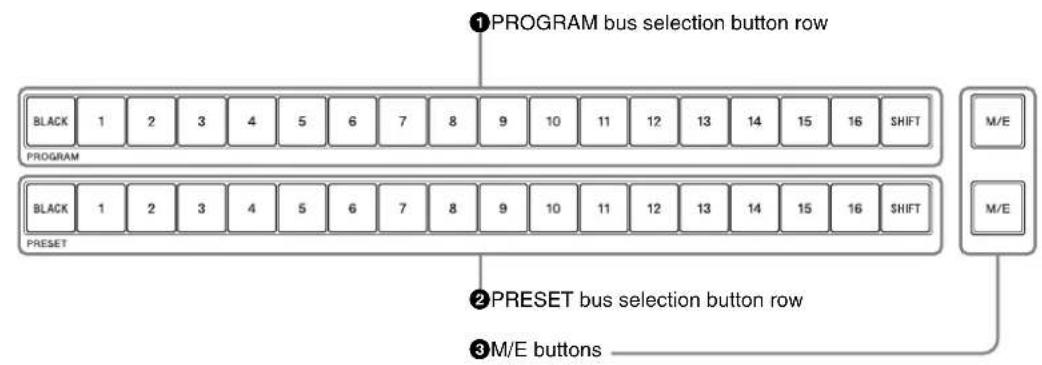
①PROGRAM bus selection button row
See descriptions for the BKDF-901 in "PROGRAM selection button row" and "About the SHIFT buttons" (page 15).
②PRESET bus selection button row
See descriptions for the BKDF-901 in "PRESET selection button row" and "About the SHIFT buttons" (page 15).
③M/E buttons
Select the M/E program video created with the M/E Cross-Point Bus Block as background video.
6 PROGRAM/PRESET Transition Block
This block allows you to set up and execute transitions of program/preset video.

flowchart
graph TD
    A["① Transition type selection buttons"] --> B["MIX"]
    A --> C["WIPE"]
    B --> D["TRANSITION TYPE"]
    C --> E["FADER LIMIT"]
    C --> F["NORM/REV"]
    C --> G["REV"]
    D --> H["DIRECTION"]
    E --> H
    F --> H
    G --> H
    H --> I["CUT"]
    H --> J["AUTO TRANS"]
    K["② Transition range and direction buttons"] --> L["3 Transition execution block"]
① Transition type selection buttons
MIX button: Press this button, lighting it, to select a mix transition. The Rate menu appears in the display panel, allowing you to specify the transition rate.
WIPE button: Press this button, lighting it, to select a wipe transition. The P/P Wipe Pattern menu appears in the display panel, allowing you to select the wipe pattern.
② Transition range and direction buttons
FADER LIMIT button: Limits the effective range of the fader lever. The range limitation is enabled when this button is pressed, lighting it. When you press the button twice to turn it on, the Fader Limit menu appears in the display panel. This menu allows you to specify the effective range of the fader lever as a percentage value.
NOR/REV (normal/reverse) button: Press this button, lighting it, to reverse the direction of the transition each time a transition is executed.
REV (reverse) button: Press this button, lighting it, to execute a transition in the reverse direction.
③ Transition execution block
See descriptions for the BKDF-901 in “Transition execution block” (page 16).
7 DSK (Downstream Key)/Fade to Black Control Block
This block allows you to set up and execute downstream keying and fade to black.

flowchart
graph TD
    A["FTB (fade to black) button"] --> B["FTB"]
    B --> C["DSK1 ON"]
    B --> D["DSK2 ON"]
    B --> E["AUTO TRANS"]
    B --> F["AUTO TRANS"]
    C --> G["DSK1"]
    D --> H["DSK2"]
    E --> I["DSK1"]
    F --> J["DSK2"]
    K["DSK (downstream key) transition buttons"] --> L["②"]
For functions of each button, see descriptions of “FTB (fade to black) button” (page 16) and “DSK (downstream key) transition buttons” (page 16) for the BKDF-901.
8 M/E Transition Block
This block allows you to set up and execute transitions of M/E video.

flowchart
graph TD
    A["①Next transition selection buttons"] --> B["NEXT TRANSITION"]
    C["②Transition type selection buttons"] --> D["MIX W/PE (FAM) DME (NAM)"]
    E["③Transition range and direction buttons"] --> F["TRANSITION TYPE"]
    G["④Key priorities block"] --> H["KEY LAYER LOW PRIORITY"]
    I["⑤Transition execution block"] --> J["CUT AUTO TRANS"]
    B --> K["NEXT TRANSITION"]
    D --> L["DIRECTION"]
    F --> M["KEY4"]
    H --> N["1 2 3 4 HSG"]
    J --> O["1 2 3 4"]
    K --> P["BKGD KEY1 KEY2"]
    L --> Q["FADER LIMIT NORM REV REV"]
    M --> R["1 2 3 4 HIGH"]
    N --> S["1 2 3 4 LOW PRIORITY"]
    O --> T["1 2 3 4 HIGH"]
    P --> U["1 2 3 4 HIGH"]
    Q --> V["1 2 3 4 HIGH"]
    R --> W["1 2 3 4 HIGH"]
    S --> X["1 2 3 4 HIGH"]
①Next transition selection buttons
See descriptions of “Next transition selection buttons” (page 16) for the BKDF-901.
② Transition type selection buttons
MIX button: Press this button, lighting it, to select a mix transition. The Rate menu appears in the display panel, allowing you to specify the transition rate.
WIPE (FAM (full additive mix)) button: Press this button, lighting it, to select a wipe transition. The M/E Wipe Pattern menu appears in the display panel, allowing you to select the wipe pattern. To select FAM, press this button while pressing the MIX button. Both buttons light.
DME (NAM (non-additive mix)) button: Press this button, lighting it, to use DME in a transition. The DME Pattern menu appears in the display panel, allowing you to select a DME wipe pattern. To select NAM, press this button while pressing the MIX button. Both buttons light.
③ Transition range and direction buttons
FADER LIMIT button: Limits the effective range of the fader lever. The range limitation is enabled when this button is pressed, lighting it. When you press the button twice to turn it on, the Fader Limit menu appears in the display panel. This menu allows you to specify the effective range of the fader lever as a percentage value.
NOR/REV (normal/reverse) button: Press this button, lighting it, to reverse the direction of the transition each time a transition is executed.
REV (reverse) button: Press this button, lighting it, to execute a transition in the reverse direction.
④Key priorities block
See descriptions of “Transition execution block” (page 16) for the BKDF-901.
⑤ Transition execution block
See descriptions of “Key priorities block” (page 16) for the BKDF-901.
9 DME/SETUP Block
This block provides buttons for use in DME setting and setup operations.

flowchart
graph TD
    A["① DME setting buttons"] --> B["DME"]
    C["② USER button"] --> B
    B --> D["USER"]
    E["③ Setup buttons"] --> F["SETUP"]
    G["④ STILL button"] --> F
    F --> H["STILL"]
①DME setting buttons
See descriptions of “DME setting buttons” (page 18) for the BKDF-901.
②USER button
Displays the menu used for management of user specified wipe patterns and DME wipe patterns.
③ Setup buttons
See descriptions of “Setup buttons” (page 18) for the BKDF-901.
④ STILL button
Displays the menu for still image storage operations, such as download, capture, and export.
10 Joystick Block
See descriptions for the BKDF-901 in "6 Joystick Block" (page 16).
11 Numeric Keypad
See descriptions for the BKDF-901 in “7 Numeric Keypad” (page 17).
12 Display Panel/Menu Control Block
See descriptions for the BKDF-901 in "9 Display Panel/Menu Control Block" (page 19).
BKDF-902 Rear Panel
Two AC IN connectors (A and B) and two POWER switches (A and B) are provided with the BKDF-902.

On how to use each connectors and switches, see descriptions in "BKDF-901 Rear Panel" (page 19).
DFS-900M Processor Unit
Front Panel

POWER switch and indicator
Powers the processor unit on and off. Press the I of the switch to power the unit on. The indicator lights in green when the unit is powered on.
You can install the optional BKDF-990 Power Supply Unit for use as a backup power supply. When installed, the BKDF-990 provides an additional power switch below the power switch of the standard power supply unit.
For details, see "Installing the BKDF-990 Power Supply Unit" (page 51).
Rear Panel

1 I/O expansion slots

①I/O expansion slot (upper)
In one slot, you can install two input expansion boards
(third and fourth boards) and one output expansion board (second board).
②I/O expansion slot (lower)
In one slot you can install two input expansion boards (first and second boards) and one output expansion board (first board).
For details, see "Installing I/O Expansion Boards" (page 39).
2 Standard I/O module

①SDI IN (SDI input) 1 to 8 connectors (BNC type)
Input SDI signals from video cameras and VTRs (players). Internal frame synchronizers are provided, allowing input of non-synchronized video signals.
②SDI OUT (SDI output) connectors (BNC type)
Output SDI signals. There are four SDI output connectors: PGM1, PGM2, AUX1, and AUX2.
PGM1, 2 (program 1, 2) connectors: Connect to the SDI input connectors of monitors or other devices. These connectors output the signals processed by this unit (program signals). The PGM1 and PGM2 connectors output the same signals.
AUX1, 2 (auxiliary 1, 2) connectors: Connect to the SDI input connectors of monitors or other devices. These connectors can output the same signals as the PGM1, 2 connectors. They can also output other types of signals, including output preview (PVW) signals, clean (CLN) signals, key output (KeyOut) signals, multi-view (MV) signals, and the input signals of this unit (In01 to In24). You can specify output of different signals from the AUX1 connector and the AUX2 connector.
Note
Input signals In09 to In24 appear only when optional input expansion boards have been installed.
3 External device interface connectors

① REF IN (reference sync signal input) connectors (BNC type)
Input an external reference sync signal. One of the connectors can be used as a loop-through output connector. If you will not be using loop-through output, terminate the connector with a 75 Ω terminator.
②REF OUT (reference sync signal output) connectors (BNC type)
If you are not using an external reference sync signal to the REF IN connector, this connector outputs the internal sync signal used by the switcher as the reference signal.
③ REMOTE 1, 2, 3 connectors (D-sub 9-pin)
These connectors are provided for connections to devices that expand the functions of the switcher, such as the optional AUX bus remote controller.
④ EDITOR connector (D-sub 9-pin)
Connect an optional editing control unit. This connector is the same type as the REMOTE 1, 2, 3 connectors, but it is for use with an editor only.
⑤ PANEL connector (RJ-45)
Use the supplied control cable to connect to the PROCESSOR connector of the control panel.
Note
This connector is for connection to the DFS-900M control panel only. It cannot be connected to the control panel of any other system.
CAUTION
- When you connect the PANEL connector of the unit to peripheral devices, use a shielded-type cable to prevent malfunction due to radiation noise.
- For safety, do not connect the connector for peripheral device wiring that might have excessive voltage to this port. Follow the instructions for this port.
ATTENTION
GPI ^1) signals input to this connector can be used to execute transitions and other switcher operations from an external device connected to this unit. 1) GPI is an abbreviation of General-Purpose Interface.
⑦ TALLY/GPI OUT (tally/GPI output) connector (D-sub 37-pin)
You can connect this connector to the tally connector of a video camera. When the camera signals are being used, red and green tally signals are sent to light the tally indicators on the camera. This connector can also be used to send GPI signals from the switcher to a connected camera or other external device.
4 Power connectors
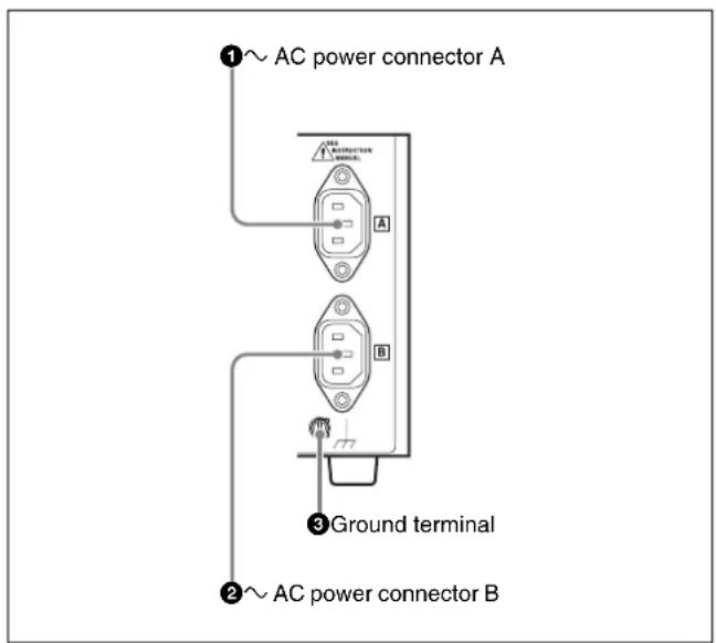
①\~ AC IN (AC power input) connector A
Connect to an AC power supply with an AC power cord (not supplied).
②\~ AC IN connector B
This connector is available when an optional power supply unit is connected.
③ Ground terminal
Connect to the system ground wire.
Options
BKDF-910 4 SDI Input Board
SDI IN 1 to 4 connectors

SDI IN (SDI input) 1 to 4 connectors (BNC type)
Input SDI signals. One board has four connectors, and up to four boards can be installed.
Together with the standard SDI input signals 1 to 8, this allows you to input up to a maximum of 24-SDI signals. Connectors 1 and 2 only are equipped with internal up-converters.
For details, see “Installing I/O Expansion Boards” (page 39) and “Making up-convert input settings” (page 81).
BKDF-911 2 SD Video Input Board
ANALOG IN (analog input) 1 to 4 connectors

ANALOG IN (analog input) 1 to 4 connectors (BNC type)
Input SD analog signals. Both composite and component signals can be input.
The following table shows the name of each connector and input signals.
| Connector number | Connector name | Input signals | |
| Composite Component | |||
| 1 COMP/Y | Composite | signal | Luminance signal (Y) |
| 2 | B-Y | Not | used signal (B-Y) |
| 3 | R-Y | Not | used signal (R-Y) |
| 4 COMP | Composite signal | ||
For signal settings, see “Specifying the signal type of analog input signals” (page 83).
BKDF-912 2 DVI Input Board
DVI IN (DVI input) 1 and 2 connectors

DVI IN (DVI input) 1 and 2 connectors (DVI-I type)
Connect a computer which is equipped with DVI output connectors.
For signal settings, see “Specifying the signal type of DVI input signals” (page 85).
BKDF-960 4 SDI Output Board

SDI OUT (SDI output) 1 to 4 connectors (BNC type)
Output SDI signals. One board has four connectors, and up to two boards can be installed.
Together with the standard SDI output signals 1 to 4, this allows you to output up to a maximum of 12 signals.
Connectors 1 and 2 only are equipped with internal down-converters.
For details, see “Installing I/O Expansion Boards” (page 39) and “Making down-convert output settings” (page 91).
BKDF-961 2 SD Video Output Board
ANALOG OUT (analog output) 1 to 4 connectors

difference
ANALOG OUT (analog output) 1 to 4 connectors (BNC type)
Output SD analog signals. Both composite and component signals can be output.
The following table shows the name of each connector and output signals.
• BKDF-950 Multi Viewer Board
| Connector number | Connector name | Output signals | |
| Composite Component | |||
| 1 COMP/Y | Composite | signal | Luminance signal (Y) |
| 2 | B-Y | Not | used signal (B-Y) |
| 3 | R-Y | Not | used signal (R-Y) |
| 4 COMP Composite signal | |||
difference
difference
For signal settings, see “Specifying the signal type of analog output signals” (page 92).
BKDF-962 2 DVI Output Board
DVI OUT (DVI output) 1 and 2 connectors

DVI OUT (DVI output) 1 and 2 connectors (DVI-I type)
Connect a computer display which is equipped with DVI input connectors.
For signal settings, see “Specifying the signal type of DVI output signals” (page 94).
BKDF-990 Power Supply Unit
Power switch B

natural_image
Pure electrical circuit lines without any symbolsPower switch B
You can install the BKDF-990 Power Supply Unit in the lower rack of the processor unit. You can then use power switch B to turn it on and off as a backup power supply.
For details, see “Installing the BKDF-990 Power Supply Unit” (page 51).
Other Options
For details about the following options, see “Installing Function Expansion Boards” (page 46).
• BKDF-940 2CH DME Board
Connecting Peripheral Devices
This section provides examples of how to connect peripheral devices. After connecting a peripheral device to the switcher, use the menu system to make basic settings.
Notes
- When you connect a device that does not allow input of external sync signals, you can achieve synchronization by enabling the frame synchronizer of the input connector to which you have connected that device. For more information about how to enable frame synchronizers, see “Using the internal frame synchronizers” (page 79).
- The switcher has two REF IN connectors. When you are using a reference sync signal generator, and do not want to perform loop-through output of the reference sync signal input to one of the REF IN connectors of the switcher, attach a 75 terminator to the other connector (see page 29). Also, use 75 termination on all devices connected to the switcher. The method for connecting the termination depends on the connected device and the connection conditions. For details, refer to the operating instructions of the connected devices.
Connection Example 1: Live Recording / Playout System
The figure below shows an example of a system configured with this switcher, several video cameras, and video output devices for the addition of special effects.
Connect the SDI output of the output devices to the SDI IN connectors of the switcher.

Chapter 3 Preparations

flowchart
graph TD
    A["Reference sync signal generator"] --> B["Monitor or other device with HD-SDI input"]
    A --> C["Recorder or other device with HD-SDI input"]
    A --> D["Monitor or other device with HD-SDI input"]
    A --> E["Projector or other device with HD-SDI input"]
    B --> F["To REF IN To PGM1 To PGM2 75 Ω terminator"]
    C --> F
    D --> F
    E --> F
    F --> G["To SDI IN1"]
    F --> H["To SDI IN2"]
    F --> I["To SDI IN3"]
    F --> J["To SDI IN4"]
    F --> K["To SDI IN5"]
    F --> L["To SDI IN6"]
    G --> M["Camera with HD-SDI output (PMW-350, etc.)"]
    H --> N["Camera with HD-SDI output (PMW-EX3, etc.)"]
    I --> O["Camera with HD-SDI output (PMW-EX3, etc.)"]
    J --> P["Camera with HD-SDI output (PMW-EX3, etc.)"]
    K --> Q["Camera with HD-SDI output (PMW-EX3, etc.)"]
    L --> R["Camera with HD-SDI output (PMW-EX3, etc.)"]
    M --> S["Key signal generator or other device with HD-SDI output"]
    N --> S
    O --> S
    P --> S
    Q --> S
    R --> S
    S --> T["Player with HD-SDI output, etc."]
    T --> U["To reference signal input"]
    U --> V["Camera with HD-SDI output (PMW-EX3, etc.)"]
    V --> W["Camera with HD-SDI output (PMW-EX3, etc.)"]
    W --> X["Camera with HD-SDI output (PMW-EX3, etc.)"]
    X --> Y["Camera with HD-SDI output (PMW-EX3, etc.)"]
    Y --> Z["Camera with HD-SDI output (PMW-EX3, etc.)"]
    Z --> AA["Camera with HD-SDI output (PMW-EX3, etc.)"]
    AA --> AB["Camera with HD-SDI output (PMW-EX3, etc.)"]
    AB --> AC["Camera with HD-SDI output (PMW-EX3, etc.)"]
    AC --> AD["Camera with HD-SDI output (PMW-EX3, etc.)"]
    AD --> AE["Camera with HD-SDI output (PMW-EX3, etc.)"]
    AE --> AF["Camera with HD-SDI output (PMW-EX3, etc.)"]
    AF --> AG["Camera with HD-SDI output (PMW-EX3, etc.)"]
    AG --> AH["Camera with HD-SDI output (PMW-EX3, etc.)"]
    AH --> AI["Camera with HD-SDI output (PMW-EX3, etc.)"]
    AI --> AJ["Camera with HD-SDI output (PMW-EX3, etc.)"]
    AJ --> AK["Camera with HD-SDI output (PMW-EX3, etc.)"]
    AK --> AL["Camera with HD-SDI output (PMW-EX3, etc.)"]
    AL --> AM["Camera with HD-SDI output (PMW-EX3, etc.)"]
    AM --> AN["Camera with HD-SDI output (PMW-EX3, etc.)"]
    AN --> AO["Camera with HD-SDI output (PMW-EX3, etc.)"]
    AO --> AP["Camera with HD-SDI output (PMW-EX3, etc.)"]
    AP --> AQ["Camera with HD-SDI output (PMW-EX3, etc.)"]
    AQ --> AR["Camera with HD-SDI output (PMW-EX3, etc.)"]
    AR --> AS["Camera with HD-SDI output (PMW-EX3, etc.)"]
    AS --> AT["Camera with HD-SDI output (PMW-EX3, etc.)"]
    AT --> AU["Camera with HD-SDI output (PMW-EX3, etc.)"]
    AU --> AV["Camera with HD-SDI output (PMW-EX3, etc.)"]
    AV --> AW["Camera with HD-SDI output (PMW-EX3, etc.)"]
    AW --> AX["Camera with HD-SDI output (PMW-EX3, etc.)"]
    AX --> AY["Camera with HD-SDI output (PMW-EX3, etc.)"]
    AY --> AZ["Camera with HD-SDI output (PMW-EX3, etc.)"]
    AZ --> BA["Camera with HD-SDI output (PMW-EX3, etc.)"]
    BA --> BB["Camera with HD-SDI output (PMW-EX3, etc.)"]
    BB --> BC["Camera with HD-SDI output (PMW-EX3, etc.)"]
    BC --> BD["Camera with HD-SDI output (PMW-EX3, etc.)"]
    BD --> BE["Camera with HD-SDI output (PMW-EX3, etc.)"]
    BE --> BF["Camera with HD-SDI output (PMW-EX3, etc.)"]
    BF --> BG["Camera with HD-SDI output (PMW-EX3, etc.)"]
    BG --> BH["Camera with HD-SDI output (PMW-EX3, etc.)"]
    BH --> BI["Camera with HD-SDI output (PMW-EX3, etc.)"]
    BI --> BJ["Camera with HD-SDI output (PMW-EX3, etc.)"]
    BJ --> BK["Camera with HD-SDI output (PMW-EX3, etc.)"]
    BK --> BL["Camera with HD-SDI output (PMW-EX3, etc.)"]
    BL --> BM["Camera with HD-SDI output (PMW-EX3, etc.)"]
    BM --> BN["Camera with HD-SDI output (PMW-EX3, etc.)"]
    BN --> BO["Camera with HD-SDI output (PMW-EX3, etc.)"]
    BO --> BP["Camera with HD-SDI output (PMW-EX3, etc.)"]
    BP --> BQ["Camera with HD-SDI output (PMW-EX3, etc.)"]
    BQ --> BR["Camera with HD-SDI output (PMW-EX3, etc.)"]
    BR --> BS["Camera with HD-SDI output (PMW-EX3, etc.)"]
    BS --> BT["Camera with HD-SDI output (PMW-EX3, etc.)"]
    BT --> BU["Camera with HD-SDI output (PMW-EX3, etc.)"]
    BU --> BV["Camera with HD-SDI output (PMW-EX3, etc.)"]
    BV --> BW["Camera with HD-SDI output (PMW-EX3, etc.)"]
    BW --> BX["Camera with HD-SDI output (PMW-EX3, etc.)"]
    BX --> BY["Camera with HD-SDI output (PMW-EX3, etc.)"]
    BY --> BZ["Camera with HD-SDI output (PMW-EX3, etc.)"]
    BZ --> CA["Camera with HD-SDI output (PMW-EX3, etc.)"]
    CA --> CB["Camera with HD-SDI output (PMW-EX3, etc.)"]
    CB --> CC["Camera with HD-SDI output (PMW-EX3, etc.)"]
    CC --> CD["Camera with HD-SDI output (PMW-EX3, etc.)"]
    DC["Reference sync generator"] <--> DD
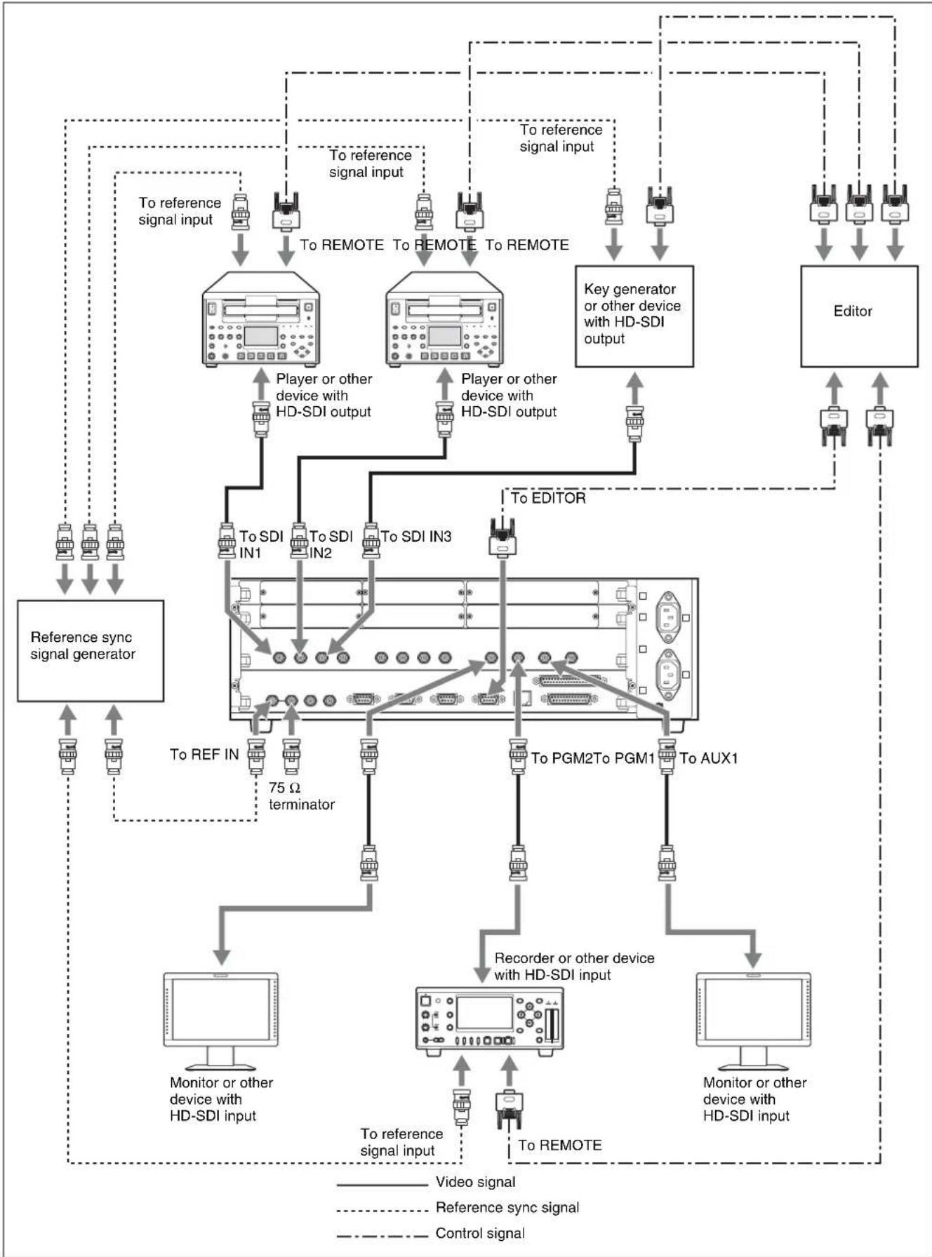
Connection Example 2: System with Editor Connected
The figure below shows an example of a video editing system with a recorder, multiple players, signal output devices, and an editor to control the other devices.
Connect the HD-SDI output of the output devices to the SDI IN connectors of the switcher.

Chapter 3 Preparations
flowchart
graph TD
    A["Reference sync signal generator"] --> B["Monitor or other device with HD-SDI input"]
    A --> C["75 Ω terminator"]
    A --> D["To REF IN"]
    A --> E["To REMOTE"]
    A --> F["To REF OUT"]
    A --> G["To REF OUT"]
    A --> H["To REF OUT"]
    A --> I["To REF OUT"]
    A --> J["To REF OUT"]
    A --> K["To REF OUT"]
    A --> L["To REF OUT"]
    A --> M["To REF OUT"]
    A --> N["To REF OUT"]
    A --> O["To REF OUT"]
    A --> P["To REF OUT"]
    A --> Q["To REF OUT"]
    A --> R["To REF OUT"]
    A --> S["To REF OUT"]
    A --> T["To REF OUT"]
    A --> U["To REF OUT"]
    A --> V["To REF OUT"]
    A --> W["To REF OUT"]
    A --> X["To REF OUT"]
    A --> Y["To REF OUT"]
    A --> Z["To REF OUT"]
    A --> AA["To REF OUT"]
    A --> AB["To REF OUT"]
    A --> AC["To REF OUT"]
    A --> AD["To REF OUT"]
    A --> AE["To REF OUT"]
    A --> AF["To REF OUT"]
    A --> AG["To REF OUT"]
    A --> AH["To REF OUT"]
    A --> AI["To REF OUT"]
    A --> AJ["To REF OUT"]
    A --> AK["To REF OUT"]
    A --> AL["To REF OUT"]
    A --> AM["To REF OUT"]
    A --> AN["To REF OUT"]
    A --> AO["To REF OUT"]
    A --> AP["To REF OUT"]
    A --> AQ["To REF OUT"]
    A --> AR["To REF OUT"]
    A --> AS["To REF OUT"]
    A --> AT["To REF OUT"]
    A --> AU["To REF OUT"]
    A --> AV["To REF OUT"]
    A --> AW["To REF OUT"]
    A --> AX["To REF OUT"]
    A --> AY["To REF OUT"]
    A --> AZ["To REF OUT"]
    A --> BA["To REF OUT"]
    A --> BB["To REF OUT"]
    A --> BC["To REF OUT"]
    A --> BD["To REF OUT"]
    A --> BE["To REF OUT"]
    A --> BF["To REF OUT"]
    A --> BG["To REF OUT"]
    A --> BH["To REF OUT"]
    A --> BI["To REF OUT"]
    A --> BJ["To REF OUT"]
    A --> BK["To REF OUT"]
    A --> BL["To REF OUT"]
    A --> BM["To REF OUT"]
    A --> BN["To REF OUT"]
    A --> BO["To REF OUT"]
    A --> BP["To REF OUT"]
    A --> BQ["To REF OUT"]
    A --> BR["To REF OUT"]
    A --> BS["To REF OUT"]
    A --> BT["To REF OUT"]
    A --> BU["To REF OUT"]
    A --> BV["To REF OUT"]
    A --> BW["To REF OUT"]
    A --> BX["TO REF IN"]
    A --> BY["TO REF IN1"]
    A --> BZ["TO REF IN2"]
    A --> CA["TO REF IN3"]
    A --> CB["TO REF IN4"]
    A --> CC["TO REF IN5"]
    A --> CD["TO REF IN6"]
    A --> DD["TO REF IN7"]
    A --> DP["TO REF IN8"]
    A --> DP2["TO REF IN9"]
    A --> DP3["TO REF IN10"]
    A --> DP4["TO REF IN11"]
    A --> DP5["TO REF IN12"]
    A --> DP6["TO REF IN13"]
    A --> DP7["TO REF IN14"]
    A --> DP8["TO REF IN15"]
    A --> DP9["TO REF IN16"]
    A --> DP10["TO REF IN17"]
    A --> DP11["TO REF IN18"]
    A --> DP12["TO REF IN19"]
    A --> DP13["TO REF IN20"]
    A --> DP14["TO REF IN21"]
    A --> DP15["TO REF IN22"]
    A --> DP16["TO REF IN23"]
    A --> DP17["TO REF IN24"]
    A --> DP18["TO REF IN25"]
    A --> DP19["TO REF IN26"]
    A --> DP20["TO REF IN27"]
    A --> DP21["TO REF IN28"]
    A --> DP22["TO REF IN29"]
    A --> DP23["TO REF IN30"]
    A --> DP24["TO REF IN31"]
    A --> DP25["TO REF IN32"]
    A --> DP26["TO REF IN33"]
    A --> DP27["TO REF IN34"]
    A --> DP28["TO REF IN35"]
    A --> DP29["TO REF IN36"]
    A --> DP30["TO REF IN37"]
    A --> DP31["TO REF IN38"]
    A --> DP32["TO REF IN39"]
    A --> DP33["TO REF IN40"]
Connection Example 3: Connection to a Device Equipped with a DVI (DVI-I) Connector
You can use the optional BKDF-912 2 DVI Input Board or the optional BKDF-962 2 DVI Output Board to connect the switcher to a computer or other device equipped with a DVI-I connector. The digital signals of the DVI-I connector are compatible with the digital output signals of the HDMI standard, and analog output signals are compatible with the analog signals of the HD15 (high-density 15-pin D-Sub) standard. You can use conversion cables and adaptors to connect them to devices equipped with HDMI or HD15 connectors.
Notes
- When you input video signals from the HDMI connectors to the switcher, the switcher can receive only progressive video signals. The switcher cannot process the video signals copy-protected by HDCP (High-bandwidth Digital Content Protection).
- If you selected “HDTV” for the DVI output signals (page 94), color difference component signals (Y/P b /P r ) are output from the analog signal output connectors of the BKDF-962. For details about the pin assignment of the BKDF-962 connector, see page 213.

Chapter 3 Preparations

flowchart
graph TD
    A["Computer"] -->|To DVI connector| B["To DVI1"]
    C["Computer"] -->|To DVI connector| D["To DVI2"]
    E["Computer"] -->|To HDMI connector| F["To DVI1"]
    G["Computer"] -->|To HDMI connector| H["To DVI2"]
    I["Monitor or other device with HD15 input connector"] --> J["Monitor or other device with DVI input"]
    B --> K["DVI-I ↔ HDMI conversion cable"]
    D --> K
    F --> K
    H --> K
    K --> L["DVI-I ↔ HD15 conversion adaptor"]
    L --> M["To HD15 input connector"]
    K --> N["To DVI1"]
    K --> O["To DVI2"]
    N --> P["Projector or other device with DVI input"]
    O --> Q["Monitor or other device with DVI input"]
Installing Optional Expansion Boards
This section explains how to install I/O expansion boards, function expansion boards, and the optional power supply unit.
The following expansion options are available. For more information about the various options, see page 31.
| Type and function of expansion options Model number | ||
| Input expansion boards | 4 SDI Input Board BKDF-910 | |
| 2 SD Video Input Board BKDF-911 | ||
| 2 DVI Input Board BKDF-912 | ||
| Output expansion boards | 4 SDI Output Board BKDF-960 | |
| 2 SD Video Output Board | BKDF-961 | |
| 2 DVI Output Board BKDF-962 | ||
| Function expansion boards | 2CH DME Board BKDF-940 | |
| Multi Viewer Board BKDF-950 | ||
| Power supply unit BKDF-990 | ||
Notes
- Always power off all devices before starting the operation for installing or removing expansion options.
- The processor unit will still be hot immediately after it is powered off. Always wait at least 30 minutes before starting the operation for installing or removing expansion options.
- Always install expansion options in the designated locations.
- Always install expansion options using the screws supplied with the expansion options. Use of other screws may damage the expansion options or processor unit.
- Be careful to avoid injury when installing and removing expansion options.
- You can use the Status sub menu of the Setup menu to check whether expansion options are installed. For details, see page 170.
Installing I/O Expansion Boards
About installation locations and channel numbers
Pull out the expansion board installation trays from the I/O expansion board slots (lower and upper) on the rear panel of the processor unit, use the screws supplied with the boards to secure them to trays, and then return the trays to the slots. Facing the processor unit, install the input expansion boards at the far left and center positions, and install the output expansion boards at the far right position.


A number is assigned to each of the channels on installed I/O expansion boards (IN09 to IN24 on input expansion boards, and AUX03 to AUX10 on output expansion boards). The following table lists the installation locations of the various boards and the numbers assigned to their channels after installation.
Notes
- Some channel numbers are invalid for some boards.
- The channel display names of I/O expansion boards can be changed to names up to four alphanumeric characters in length. For details, see page 74.
Input expansion board channel numbers
| Installation position on expansion board installation tray | |||||||
| Lower tray Upper tray | |||||||
| Left | Center | Right | Left | Center | Right | ||
| Whether board can be installed | Yes | Yes | No | Yes | Yes | No | |
| Input number display after installation | BKDF-9104 SDI Input Board | IN09 to IN12 | IN13 to IN16 | - | I IN20 | NIN21 to 1 IN24 | -7 |
| BKDF-9112 SD Video Input Board | IN09 to IN10a) | IN13 to IN14b) | - | I IN18c) | NIN21 to 1 IN22d) | -7 | |
| BKDF-9122 DVI Input Board | |||||||
a) IN11 and IN12 are invalid.
b) IN15 and IN16 are invalid.
c) IN19 and IN20 are invalid.
d) IN23 and IN24 are invalid.
Output expansion board channel numbers
| Installation position on expansion board installation tray | |||||||
| Lower tray Upper tray | |||||||
| Left | Center | Right | Left | Center | Right | ||
| Whether board can be installed | No No | Yes No | No Yes | ||||
| Output number display after installation | BKDF-9604 SDI Output Board | - | - | A to AUX06 | - U | - X | AUX07 to AUX10 |
| BKDF-9612 SD Video Output Board | - | - | A to AUX04a) | - U | - X | AUX07 to AUX08b) | |
| BKDF-9622 DVI Output Board | |||||||
a) AUX05 and AUX06 are invalid.
b) AUX09 and AUX10 are invalid.
To install I/O expansion boards
Use the following procedure to install expansion boards. (The example figures show the lower expansion board tray, but the procedure is the same for the upper tray.)
1 Remove the four screws (+B 3×6) securing the board tray stabilizers, and remove the stabilizers.
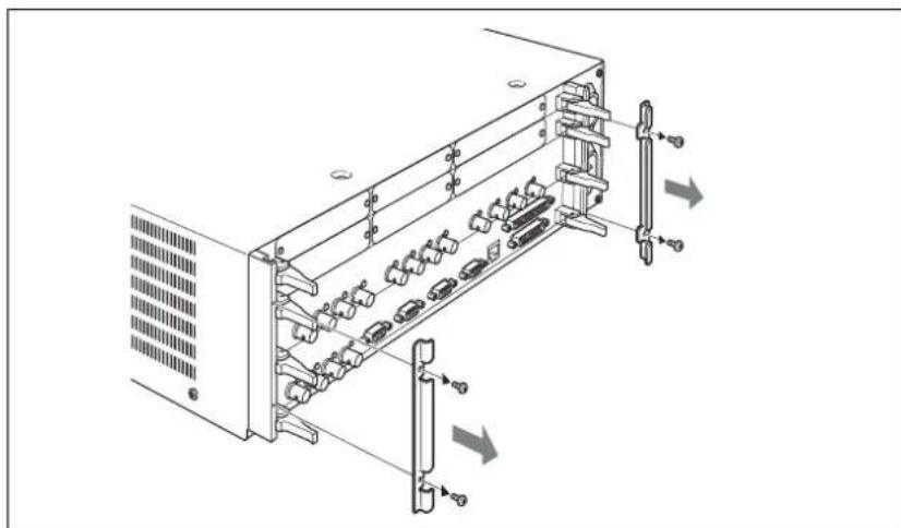
natural_image
Technical line drawing of a server rack with multiple ports and connectors (no text or symbols)2 As shown in the figure below, push the levers on each end of the expansion board installation tray to open them, and then pull the tray out.


natural_image
Diagram of an internal server rack with ports and connectors, showing no text or symbols3 Use the following procedure to remove the panels on the expansion board installation tray.
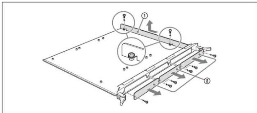
①Remove the two screws (+M3) securing the ventilation adjustment panel, and remove the ventilation adjustment panel.
②Remove the two screws (+M2.6) securing the blank panel where you want to install an I/O expansion board, and remove the blank panel.
Notes
- Do not discard the panels. Retain them for future use. If you remove an I/O expansion board, you will need to reattach the blank panel. If you remove all I/O expansion boards, reattach the ventilation adjustment panel.
- Use the screws that secured the blank panel to secure the I/O expansion board. For details, see step 5. Keep the screws that secured the ventilation adjustment panel together with the ventilation adjustment panel.
4 Use the following procedure to affix the heat transfer sheet (supplied with each I/O expansion board) to the expansion board installation tray.
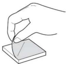
①Remove the adhesive surface cover sheet from one side only of the heat transfer sheet.
natural_image
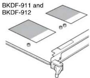
Hand holding a small object on a square base, no text or symbols visible②Hold the bottom side of the heat transfer sheet (the side from which you removed the adhesive cover sheet) down and affix it to the expansion board installation tray, aligning it with the positioning guide frame on the expansion board installation tray.
Positioning guide frames (for input expansion board)
Positioning guide frame (for output expansion board)

natural_image
Technical diagram of a mechanical assembly with two components and directional arrows indicating movement (no text or symbols)I/O expansion board heat transfer sheet affixation position (shaded part)


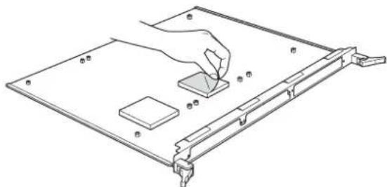
③Remove the adhesive surface cover sheet from the top side of the heat transfer sheet.
natural_image
Line drawing of a computer monitor with a hand inserting a component into the screen (no text or symbols)(For input expansion boards)

natural_image
Line drawing of a hand inserting a small component into a flat panel (no text or symbols)(For output expansion boards)
5 Push the connectors of the expansion board through the inner side of the connector name plate frame, place the expansion board on the expansion board installation tray, and secure the board with the supplied four +M3 screws.
Notes
- Use a torque screwdriver to tighten the screws. Set the tightening torque to 0.59 ~N · m .
- For the installation positions of expansion boards, see page 39.

natural_image
Technical line drawing of a mechanical assembly with mounting brackets and internal components (no text or symbols)6 Use the following procedure to attach the connector name plate supplied with the expansion board.
①Using the screws (see the following table) supplied with the expansion board, secure the connector name plate to the expansion board.
| Expansion board Screws Tightening torque | ||
| BKDF-910 | +M2.6 × 4 0.49N·m | |
| BKDF-911 | ||
| BKDF-960 | ||
| BKDF-961 | ||
| BKDF-912 | Hexagon head bolt(5mm in width across flats) × 4 | 0.5N·m |
| BKDF-962 | ||
Note
For the BKDF-912 and BKDF-962, use a nut driver to tighten the hexagon head bolt.
②Using the two screws removed in step 3, secure the connector name plate to the expansion board installation tray.
Note
Set the tightening torque to 0.49 N·m for step 6-②.

7 Insert the expansion board installation tray into its original slot, and align the notches of the levers on both sides of the tray to the left and right sides of the slot mouth.
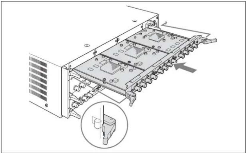
natural_image
Diagram of a server rack with internal components and an inset view showing a device (no text or symbols present)8 As shown in the figure below, lock the tray by pulling the tray levers toward the inside.
The tray is pushed all the way into the slot and locked in place.


natural_image
Diagram of a server rack with multiple ports and a close-up inset showing mechanical components (no text or symbols)9 Using the four screws removed in step 1, attach the board tray stabilizers.

natural_image
Technical diagram of an internal server rack with multiple ports and connectors, showing mounting hardware (no text or labels)To remove I/O expansion boards
Carry out the installation procedure in reverse.
Installing Function Expansion Boards
About installation locations
Pull the standard I/O module out from the rear panel of the processor unit, and install the function expansion boards on the standard I/O module. Insert the expansion board connectors into the sockets on the standard I/O module and secure them with the screws supplied with the expansion boards. Connect the BKDF-940 to the DME1 and DME2 sockets, and connect the BKDF-950 to the MV1 and MV2 sockets.
Yes: Can be installed No: Cannot be installed
| Function expansion board | Socket on standard I/O module | |||
| DME1 socket | DME2 socket | MV1 socket | MV2 socket | |
| BKDF-940 2CH DME Board | YesYesNoNo | |||
| BKDF-950 Multi Viewer Board | No No Yes Yes | |||

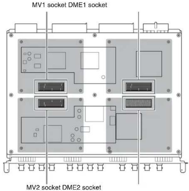
To install function expansion boards
Use the following procedure to install function expansion boards.
1 Remove the four screws (+B 3×6) securing the board tray stabilizers, and remove the stabilizers.
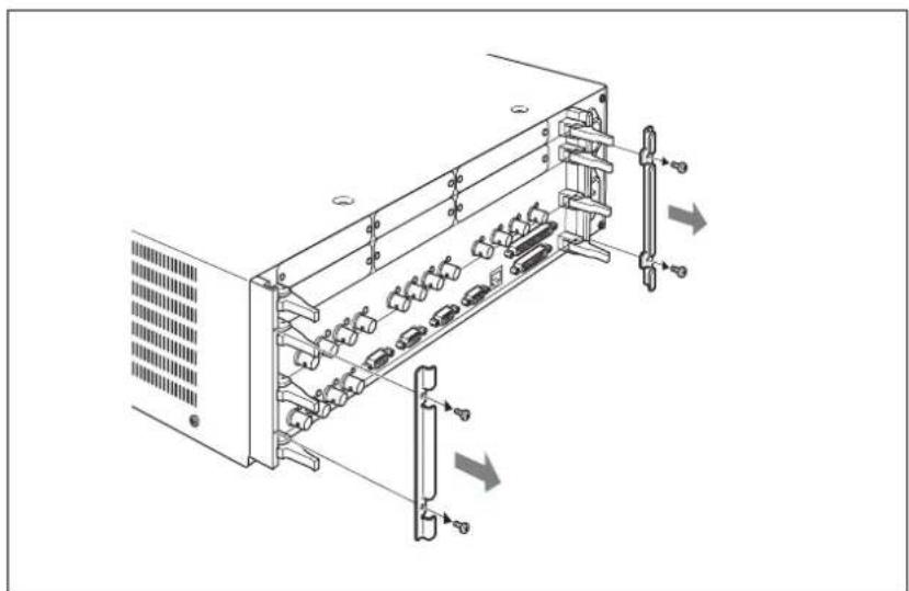
natural_image
Technical line drawing of a server rack with multiple ports and ventilation slots (no text or symbols)2 As shown in the figure below, push the levers on each end of the standard I/O module to open them, and then pull the standard I/O module out.


natural_image
Technical illustration of a server rack with multiple ports and directional arrows indicating flow or movement (no text or symbols present)3 If you are installing the BKDF-940, proceed as follows to affix the heat transfer sheet supplied with the BKDF-940 to the function expansion board.
①Remove the adhesive surface cover sheet from one side only of the heat transfer sheet.

natural_image
Hand holding a small object on a square base, no text or symbols visible②Hold the bottom side of the heat transfer sheet (the side from which you removed the adhesive cover sheet) down and affix it to the standard I/O module, aligning it with the positioning guide frame on the standard I/O module.

③Remove the adhesive surface cover sheet from the top side of the heat transfer sheet.
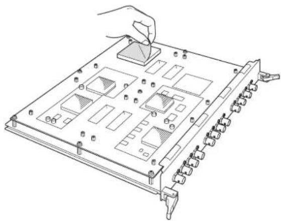
natural_image
Technical line drawing of a multi-chamber electronic device with ports and connectors (no text or symbols)4 Align the connectors of the function expansion board with the sockets on the signal processing board of the standard I/O module, grasp the board near the connector, and push the board down until the connector is coupled into the socket.
Note
For the installation location of each expansion board, see page 46.

natural_image
Technical line drawing of a server rack with multiple ports and connectors (no text or symbols)5 Using the four +M3 screws supplied with the function expansion board, secure the expansion board to the signal processing board of the standard I/O module.
Note
Use a torque screwdriver to tighten the screws. Set the tightening torque to 0.59 N·m.

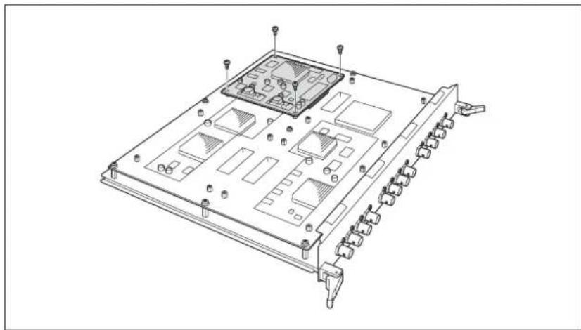
natural_image
Technical line drawing of a multi-chamber electronic device chassis with ports and connectors (no text or symbols)6 Insert the standard I/O board into its original slot, and align the notches of the levers on both sides of the board to the left and right sides of the slot mouth.
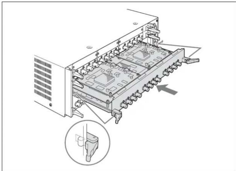
natural_image
Diagram of a server rack with internal components and an inset showing a device component (no text or symbols present)7 As shown in the figure below, lock the standard I/O module by pulling the levers toward the inside.
The standard I/O module is pushed all the way into the slot and locked in place.
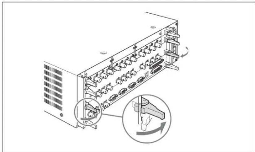
natural_image
Diagram of a server rack with internal components and a close-up inset showing hand movement (no text or symbols)8 Using the four screws removed in step 1, attach the board tray stabilizers.

natural_image
Technical diagram of a server rack with multiple ports and connectors, showing internal components and directional arrows (no text or labels)To remove function expansion boards
Carry out the installation procedure in reverse.
Installing the BKDF-990 Power Supply Unit
To install the BKDF-990
Remove the front panel of the processor unit, remove the internal blank panel, and then install the BKDF-990.
1 Remove the two screws securing the front panel of the processor unit, and remove the panel.


natural_image
Line drawing of a server rack with two circular buttons and a directional arrow indicating motion (no text or symbols)2 Remove the two screws (+B 4×8) securing the blank panel inside the processor unit, and remove the blank panel.

natural_image
Technical line drawing of a server rack with ventilation slots and an internal component, showing no text or symbols.3 Insert the BKDF-990 into the installation slot inside the processor unit, and push it all the way in.

natural_image
Technical diagram of a server rack with two connectors and a highlighted internal portion (no text or symbols)4 Using the two screws removed in step 2, secure the BKDF-990 to the processor unit.

natural_image
Technical line drawing of a server rack with ports and connectors (no text or symbols)5 Using the two screws removed in step 1, attach and secure the front panel.
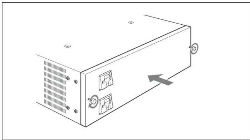
natural_image
Diagram of a server rack with two buttons and a directional arrow indicating movement (no text or symbols)To remove the BKDF-990
Power off the BKDF-990, and then carry out the installation procedure in reverse.
Connecting Up the Switcher
This section explains how to connect up the switcher system.
Changing the Internal Switch Setting in the Processor Unit (When Using the BKDF-902)
When using the BKDF-902, change the setting of a DIP switch on the external device interface connectors board in the processor unit.
Note
When using the BKDF-901, you need not perform the following procedure.
1 Remove the four screws (+B 3×6) securing the board tray stabilizers, and remove the stabilizers.

natural_image
Technical diagram of a server rack with multiple ports and connectors, showing internal components and directional arrows (no text or labels)2 As shown in the figure below, push the levers on each end of the external device interface connectors board to open them, and then pull the board out.

natural_image
Diagram of a server rack with multiple ports and directional arrows indicating internal components (no text or symbols present)3 Set pin 2 of the DIP switch under the flat cable to the "ON" position.

Note
Do not change settings of the other pins.
4 Insert the external device interface connectors board into its original slot, and align the notches of the levers on both sides of the board to the left and right sides of the slot mouth.


natural_image
Diagram of an internal network device with connectors and a close-up inset showing a connector (no text or symbols present)5 As shown in the figure below, lock the board by pulling the levers toward the inside.
The board is pushed all the way into the slot and locked in place.

natural_image
Diagram of a server rack with multiple ports and connectors, showing internal components and directional arrows (no text or symbols)6 Using the four screws removed in step 1, attach the board tray stabilizers.

natural_image
Technical diagram of an internal server rack with multiple ports and connectors, showing no text or symbols.Connecting the Processor Unit and the Control Panel
Using the control cable supplied with the processor unit, connect the PANEL connector of the processor unit and the PROCESSOR connector of the control panel. After connecting the control cable, use two AC power cords (not supplied) to connect the processor unit and the control panel to an AC power source. Note that one more AC power cord is required when the BKDF-990 is installed.
Notes
• Always power off all devices before connecting.
- If you will not be connecting the BKDF-990, connect the AC power cord of the processor unit to the upper AC IN connector.
- If you want to attach the supplied rack mounting bracket to the control panel, refer to the figure on page 215 for the attachment position. Use the screws supplied with the rack mounting bracket to attach the bracket to the control panel.
- If you want to attach a rack mounting bracket to the processor unit, use the optional RMM-10 Rack Mount Kit. Refer to the Installation Manual of the RMM-10 for information about how to attach the RMM-10.

When using the BKDF-901

flowchart
graph TD
    A["BKDF-901 control panel"] --> B["To PROCESSOR"]
    B --> C["Control cable (supplied)"]
    C --> D["To PANEL"]
    D --> E["Processor unit"]
    E --> F["To AC power"]
    F --> G["To AC IN"]
    G --> H["AC power cord (not supplied)"]
    H --> I["To AC power"]
    style A fill:#f9f,stroke:#333
    style E fill:#ccf,stroke:#333
    style F fill:#cfc,stroke:#333
    style G fill:#fcc,stroke:#333
When using the BKDF-902

Powering the System On
After connecting up the system, proceed as follows to power it on.

natural_image
Front view of a rectangular electronic device with a labeled component (no text or symbols visible)
natural_image
Front view of a rectangular electronic device with a labeled component (no text or symbols visible)

natural_image
Back view of a computer rack with ventilation slots, ports, and an attached switch (no text or symbols visible)
BKDF-902 BKDF-901

natural_image
Line drawing of a computer control panel with labeled components (no text or symbols beyond basic layout)1 Turn on the POWER switch on the processor unit by pressing the I of the switch.
The processor unit is powered on, and the POWER indicator lights in green.
2 Turn on the POWER switch (when using the BKDF-901) or the POWER switches A and B (when using the BKDF-902) on the rear panel of the control panel.
The control panel is powered on, and the panel buttons and display panel light.
The control panel enters boot mode after the power is turned on. Several minutes are required before the control panel can be operated.
When the control panel exits boot mode, the following information appears in the display panel.


Tip
The following messages appear in the display panel during boot mode. Now Initializing...Please Wait...: Initializing Now initial communication started.: Establishing communication between the control panel and the processor unit
3 Pull the fader lever once from the top of its range all the way to the bottom.
4 Power on the peripheral devices.
To power off
Notes
- Always use the following procedure to power off. If you power off without carrying out the correct procedure, the current control panel settings will not be saved, and the switcher may become unable to boot normally.
- If you have connected a USB flash drive, remove it before powering off.


natural_image
Back view of a computer chassis showing ports, connectors, and a power outlet (no text or symbols visible)
natural_image
Front view of a rectangular electronic device with a small internal component and labeled pin (no text or symbols beyond the number 4)
natural_image
Front view of a rectangular electronic device with a small internal component and a grid-patterned side panel (no text or symbols visible)BKDF-902 BKDF-901
1 Press the SHUTDOWN button.
The following message appears in the display panel.
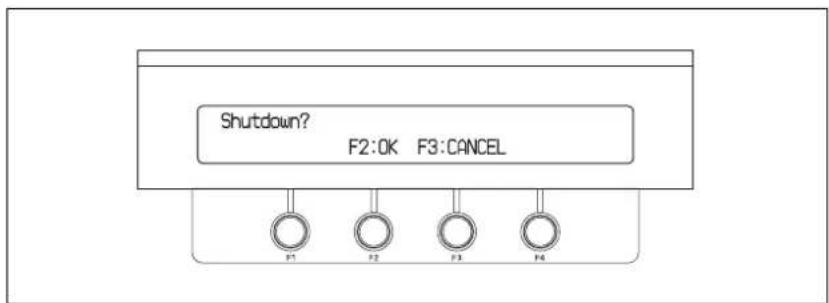
2 Press the F2 knob.
Shutdown processing (storage of the various settings) begins.
When storage of the setting ends, the following message appears in the display panel.

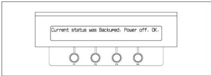
Note
Do not turn off the power switches during shutdown processing. If you turn off the power before the shutdown finishes, the switcher may become unable to boot normally.
3 Turn off the POWER switch (when using the BKDF-901) or the POWER switches A and B (when using the BKDF-902) on the rear panel of the control panel.
4 Turn off the POWER switch on the processor unit.
Menu Operations
Menus shown in the display panel allow you to make settings for the entire system, select effects, and so on. This section explains the types of menus, the configuration of the menu system, and basic menu operations.
Basic Menu Configuration
The menus of this switcher are divided into the following categories, depending on the type of operation and the setting target.
- Transition (transition rate, wipe, and DME settings) menu
Allows you to select and adjust transition rates, wipes, and DME effects.
- Keyer (key settings) menu
Allows you to select and adjust transition keys, and the select and adjust DME effects for application to keys.
- Still Store (still image settings) menu
Allows you to capture, save, and select still image files to be used for keying.
- Sequence/Event (sequence and event settings) menu
Allows you to register combinations of multiple transitions and DME effects, so that the set of transitions and effects can be recalled and used as required.
- Setup (system settings) menu
Allows you to make basic system settings, such as video format selection and signal assignments to I/O connectors.
Specific function settings and adjustments are made in the sub menus beneath each menu. Sub menus with many setting items have a hierarchical structure.
For a list of the sub menus beneath each menu, see page 176.
Displaying Menus
When you press a button on the control panel to select a function or perform an operation, a menu related to that function or operation appears in the display panel.
When the menu structure is deep or there are many divisions between setting items, the most recently set sub menu appears. You can press the ◀◀, ▶▶, ◀, and ▷ buttons on the numeric keypad to move to the sub menu that you want to set.
For details, see the descriptions of the various operations. For a description of the menu and sub menu configuration, see page 176.
Note
You must put the numeric keypad into menu mode before you use the ◀, ▷, ◀◀, and ▷◀ buttons to switch between sub menus. For information about how to switch to menu mode, see page 17.


Operating in Menus
Use the F1 to F4 adjustment knobs to change and save settings.
Setting names and values appear in the display panel above the corresponding adjustment knobs.

Adjustment knob operations
Basic operations with the adjustment knobs are as follows.
Rotate clockwise: Increase a setting value, or display the next setting item.
Rotate counterclockwise: Decrease a setting value, or display the previous setting item.
Press (when numeric input is required): Enter numeric keypad mode.
Tip
Some knob may return a setting to its factory default value when it is pressed and held for one second or longer.
Menu Operations in the GUI Menus
You can connect a PC monitor and a USB mouse to the switcher. This allows you to select items in menus and sub menus while viewing a GUI menu screen
in the monitor. This can be an aid to smooth operations because it allows you to take in the entire menu system and several menu levels at a glance.
Instead of the mouse and monitor, you can also connect a commercially available touch panel monitor. This allows you to select menu items by touching the panel directly.
Connecting devices needed for display and operation
Connecting a PC monitor and USB mouse
Connect the video input connector of the monitor to the EXT.DISPLAY connector on the rear panel of the control panel, and connect a USB mouse to the DEVICE connector on the rear panel of the control panel.

flowchart
graph TD
    A["PC monitor"] --> B["To video input connector"]
    B --> C["To EXT.DISPLAY"]
    C --> D["Device with USB mouse"]
    D --> E["Device with To Device"]
    E --> F["Device with To Device"]
    style A fill:#f9f,stroke:#333
    style B fill:#ccf,stroke:#333
    style C fill:#cfc,stroke:#333
    style D fill:#fcc,stroke:#333
    style E fill:#cff,stroke:#333
    style F fill:#ffc,stroke:#333
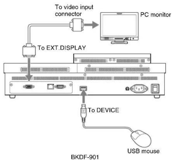
Connecting a touch panel monitor
Connect the video input connector of the monitor to the EXT.DISPLAY connector on the rear panel of the control panel, and connect the USB connector of the monitor to the DEVICE connector on the rear panel of the control panel.


Tip
When selecting a PC monitor or touch panel monitor to connect to this switcher, select one with at least SVGA (800×600) resolution and the ability to adjust the resolution automatically.
To calibrate a touch panel monitor
If you have connected a touch panel monitor, you must calibrate it when you power the switcher on for the first time.

BKDF-902
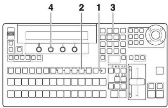
BKDF-901
1 When using the BKDF-901: If the SHIFT button of the DME/SETUP block is not lit, press it to light it.
When using the BKDF-902: Skip to step 2.
2 Press the SYSTEM button.
A settings sub menu of the System sub menu appears in the display panel.
3 Press the ◀ or ▷ button in the numeric keypad until the Update sub menu appears.
"Update" appears in the sub menu title display area. If it is already displayed there, you can skip this step.

4 Press the F2 knob and hold it down for one second or longer.
A calibration screen appears on the touch panel monitor.
5 Press the center point of the calibration mark in the upper left corner of the screen.
The mark disappears when you press it, and another mark appears in the bottom right corner of the screen.

6 Press the center point of the calibration mark in the bottom right corner of the screen.
The mark disappears when you press it, and another mark appears in the upper right corner of the screen.

7 Press the center point of the calibration mark in the upper right corner of the screen.
A confirmation message appears asking whether you have finished the calibration.

8 Press the mark on the screen.
The control panel is powered off and then starts again automatically. The new settings are reflected when it starts again. Press the ☐ mark to return to the calibration screen of step 4.
Note
Calibrate the touch panel monitor again if you notice that a touch position is different from the display position.
GUI menu screen configuration

①Menu category section
Displays tabs (menu selection tabs) for each of the five categories in the basic menu configuration (see page 63). When you select a tab, the sub menus for that menu appear in the sub menu section ②.
②Sub menu section
Displays tabs for the sub menus in the menu that was selected in the menu category section 1.
③Status section
Displays the number of DME channels in use, the transition rate, and other status information.
④Parameter section
Displays the current settings of the current sub menu.
Basic operations in the GUI menu screens
To select menu and sub menu items
If you have connected a PC monitor and a USB mouse, move the cursor to the menu or sub menu item that you want to set, and then left click the mouse. If you have connected a touch panel monitor, you can select a menu or sub menu item by touching the item directly.
To make sub menu settings
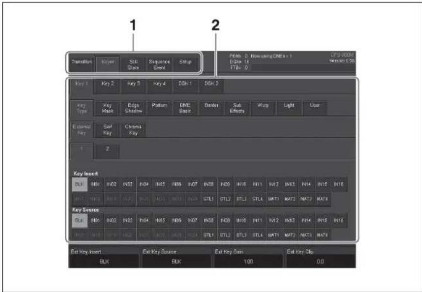
1 In the menu category section, select a menu tab.
Tabs for the sub menus in that menu appear in the sub menu section.
2 Select the tab of the sub menu that you want to set.
The sub menu is selected, and its current settings appear in the parameter section. If the sub menu has a number of levels, you can display the settings for a deeper sub menu by touching its tab, which appears beneath the settings for the current sub menu.
3 Use the F1 to F4 knobs on the control panel to set parameter values.
The figure below shows the correspondence between knobs and menu displays. The procedures for operating in the menus and setting parameters are the same as those for normal menus. For details, see “Operating in Menus” (page 64).

Note
The names of menus and sub menus in the GUI menu screens differ from the names that appear in the display panel of the control panel. See page 176 for a list of menus and their names as they appear in GUI menu screens and the display panel.
Basic Switcher Settings
This section explains how to make settings that must be made before you can operate the switcher, such as the video format, the selection of I/O channels, etc.
Setting the Video Format
Use the following procedure to set the format of the video signals handled by the switcher.

BKDF-902

BKDF-901
1 When using the BKDF-901: If the SHIFT button of the DME/SETUP block is not lit, press it to light it.
When using the BKDF-902: Skip to step 2.
2 Press the SYSTEM button.
A settings sub menu of the System sub menu appears in the display panel.
3 Press the ◀ or ▷ button in the numeric keypad until the Type (video format selection) sub menu appears.
“Type” appears in the sub menu title display area. If it is already displayed there, you can skip this step.

4 Rotate the F1 knob to select the video format.

525/59: SD signal (NTSC)
625/50: SD signal (PAL)
720/50: HD signal (720p/50 Hz)
720/59: HD signal (720p/59.94 Hz)
1080/50: HD signal (1080i/50 Hz)
1080/59: HD signal (1080i/59.94 Hz)
Note
Settings values are highlighted if they are different from the current setting value.
5 Hold the F1 knob down for one second or longer.
A message appears to confirm the selection of the video format.

6 Press the F2 knob.
The video format selected in step 3 is confirmed.
To cancel the selection, press the F3 knob. This returns to the video format selection screen of step 3.
Note
When you have changed the video format, you need to restart the switcher. On how to power the switcher off, see "To power off" (page 60).
7 Rotate the F4 knob to set the system delay.
Normal: The frame synchronizers for the input connectors (see page 79) are enabled automatically.
Min (Minimum): System delay is held to the minimum. If the frame synchronizers for the input connectors are disabled, the delay with respect to the reference sync signal is 1H.
Tip
The amount of system delay varies depending on DME and frame synchronizer usage.
8 Restart the switcher.
Settings when an SD format (525/59 or 625/50) is selected
When an SD format is selected in steps 3 to 6, set the black setup level (SET) with the F2 knob (for 525/59 only), and set the aspect (SD ASPECT) with the F3 knob.
The selection items and what they select are as follows.
F2 knob (SET) setting
0.0%: Set the black setup level to 0%.
7.5%: Set the black setup level to 7.5%.
F3 knob (SD ASPECT) setting
4: 3: Video with aspect ratio of 4: 3
SQ: Squeeze video
Note
If you have connected a black burst signal to the REF IN connector of the switcher, and SET is set to 7.5%, then a 7.5% setup level is added to the black burst signals (both SD and HD) output from the REF OUT connector.
Making Input and Output Reference Sync Signal Settings
Use the following procedure to specify a reference sync signal input to the switcher, and a reference sync signal generated and output by the switcher.

BKDF-902
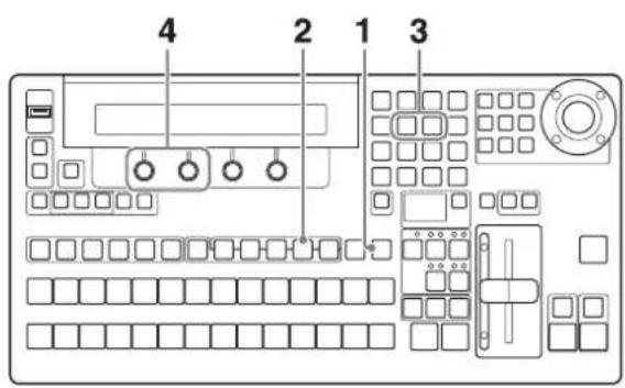
BKDF-901
1 When using the BKDF-901: If the SHIFT button of the DME/SETUP block is not lit, press it to light it.
When using the BKDF-902: Skip to step 2.
2 Press the SYSTEM button.
A settings sub menu of the System sub menu appears in the display panel.
3 Press the ◀ or ▷ button in the numeric keypad until the Ref (reference sync signal settings) sub menu appears.
“Ref” appears in the sub menu title display area. If it is already displayed there, you can skip this step.


4 Make the reference sync signal settings.
Rotate the F1 knob to specify an input sync signal, and rotate the F2 knob to specify an output sync signal.
The correspondence between knobs and parameters is as follows.
| Knob | Parameter | Description | Setting range |
| F1 Ref- | Input reference | sync signal | BB: Black burst signalTriS: Tri-level sync signal a) |
| F2 Ref- | O Output reference | sync signal | BB: Black burst signalTriS: Tri-level sync signal a) |
a) Selectable only when the video format is set to an HD signal (720/50, 720/59, 1080/50, 1080/59) (see page 71).
Note
When the video format is set to 1080/59 or 525/59, and you set Ref-O to BB, the setting of Set (see page 71) in the System >Type sub menu is also reflected in the reference sync signal.
Making Settings Related to Input Signals
Changing signal display names
You can change the input signal names displayed in menus to user-specified names up to four alphanumeric characters long.
To change the names, save a text file containing a list of the current signal names to a USB flash drive, edit the names on a computer, and then load the edited list into the switcher.
Tip
Signals have the following display names when the switcher is shipped from the factory.
| Signal name Signal | |
| BLK Black signal | |
| IN01 to IN08 (numbers are channel numbers) | Input signals connected to the SDI IN 1 to 8 connectors |
| IN09 to IN24 (numbers are channel numbers) | Input signals connected to optional input expansion boards, when the optional boards are installed |
| STL1 to STL4 Still images stored in the processor unit | |
| MAT1 to MAT4 Color matte signals for use in backgrounds, etc. | |

1 Insert a USB flash drive into the USB MEMORY connector.
2 When using the BKDF-901: If the SHIFT button of the DME/SETUP block is not lit, press it to light it.
When using the BKDF-902: Skip to step 3.
3 Press the INPUT button.
A settings sub menu of the Input (input signal settings) sub menu appears in the display panel.
4 Press the ◀ or ▷ button in the numeric keypad until the Signal Rename sub menu appears.
"Signal Rename" appears in the sub menu title display area. If it is already displayed there, you can skip this step.

flowchart
graph TD
    A["Signal Rename\nSave"] --> B["F1"]
    A --> C["F2"]
    A --> D["F3"]
    A --> E["F4"]
    A --> F["Download"]
5 Hold the F1 knob down for one second or longer.
A file containing a list of the signal names (dfs900.ini) is saved in the root directory of the USB flash drive.
The file is a text file, with content in the following format.

![[InputShot] Black = BLK Input01 = In01 Input02 = In02 Input03 = In03 Input04 = In04 Input05 = In05](/content/2026/05/940902/images/aa4d2e3b1edadc515cf2b25f3f2a86f553b438ca3e249d99fd8df88616f7b1f2.jpg)
6 Remove the USB flash drive from the USB MEMORY connector, and load the file into a computer.
7 Use Notepad or another text editor to edit the display names (the strings after the equals signs).
The following characters can be used in display names. The maximum number of characters per name is four.
- Numbers: 0 to 9
• Alphabetic characters: a to z, A to Z - Space
- Symbols: ! " # \$ % & ' ( ) * + , - . / : ; <= > ? @ [ \ ] ^ _ ` { | } \~
Note
- Display names will not be displayed correctly if you use any characters other than those listed above. If a display name is longer than four characters, the fifth and following characters are not displayed.
- You can also change the names of channel numbers that have been assigned to optional input expansion boards. But channel number names are not displayed for boards that are not installed and for channel numbers that (depending on the board) are invalid. For information about channel numbers of input expansion board, see page 40.
8 Save the edited name file to the USB flash drive, overwriting the old file, and then insert the USB flash drive into the USB MEMORY connector.
9 Repeat steps 2 to 4 to display the Signal Rename sub menu, and then hold the F4 knob down for one second or longer.
The edited file is read into the switcher, and the signal display names in menus change to the edited names.
Tip
The dfs900.ini file contains instructions that specify how to display child window titles in multi-view output (see page 96). You can edit those instructions to change the display position and size of child window titles. For details, see page 99.
Assigning video input signals to cross-point selection buttons
When using the BKDF-901
Use the following procedure to assign video input signals to PROGRAM and PRESET selection buttons (BLACK and 1 to 12). Each assignment assigns the same signal to the PROGRAM and PRESET selection buttons with the same numbers.
When optional input expansion boards are installed, you can use the SHIFT buttons to assign up to 26 signals, including video input signals 1 to 24, four color matte signals, four still images, and a black signal.
Tip
The following signals are assigned when the switcher is shipped from the factory.
| PROGRAM/PRESET selection buttons | Video signals Video signals (specified with SHIFT button) | |
| BLACK Black signal | black signal | |
| 1 to 8 Signals connected to the SDI IN1 to IN8 connectors | Signals connected to optional input expansion boards | |
| 9 Still image 1 Color | matte 1 | |
| 10 Still image 2 Color | matte 2 | |
| 11 Still image 3 Color | matte 3 | |
| 12 Still image 4 Color | matte 4 | |
When using the BKDF-902
Use the following procedure to assign video input signals to KEY/AUX bus selection buttons (BLACK and 1 to 16), M/E bus A and B selection buttons (BLACK and 1 to 16), and PROGRAM and PRESET bus selection buttons (BLACK and 1 to 16). Each assignment assigns the same signal to the KEY/AUX bus selection buttons, the M/E bus A and B selection buttons, and the PROGRAM and PRESET bus selection buttons with the same numbers. When optional input expansion boards are installed, you can use the SHIFT buttons to assign up to 26 signals, including video input signals 1 to 32, four color matte signals, four still images, and a black signal.
Tip
The following signals are assigned when the switcher is shipped from the factory.
| Cross-point selection buttons | Video signals Video signals (specified with SHIFT button) | |
| BLACK Black signal B | black signal | |
| 1-4 Signals connected | to the SDI IN1 to IN4 connectors | Signals connected to optional input expansion boards (IN17-IN20) |
| 5-8 Signals connected | to the SDI IN5 to IN8 connectors | Signals connected to optional input expansion boards (IN21-IN24) |
| 9 Signals connected to | optional input expansion boards (IN9-IN12) | Still image 1 |
| 10 Still image 2 | ||
| 11 Still image 3 | ||
| 12 Still image 4 | ||
| 13 Signals connected to | optional input expansion boards (IN13-IN16) | Color matte 1 |
| 14 Color matte 2 | ||
| 15 Color matte 3 | ||
| 16 Color matte 4 | ||


BKDF-902
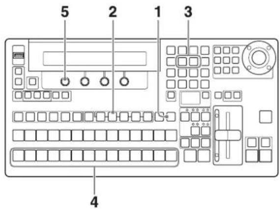
BKDF-901
1 When using the BKDF-901: If the SHIFT button of the DME/SETUP block is not lit, press it to light it.
When using the BKDF-902: Skip to step 2.
2 Press the INPUT button.
A settings sub menu of the Input sub menu appears in the display panel.
3 Press the ◀ or ▷ button in the numeric keypad until the Setting 1 sub menu appears.
"Setting1" appears in the sub menu title display area. If it is already displayed there, you can skip this step.

4 When using the BKDF-901: In the PRESET selection button row, press the button to which you want to assign a signal.
When using the BKDF-902: In the M/E bus B selection button row, press the button to which you want to assign a signal.
If you press the SHIFT button before pressing the button to which you want to assign the signal, you can assign a second signal to that button, in addition to the signal assigned without pressing the SHIFT button.
5 Rotate the F1 knob to select the signal.
A list of signal names, specified with the procedure described in “Changing signal display names” (page 74), appears in the menu screen. The selected signal is assigned to the selected button.
6 Repeat steps 4 and 5 to assign signals to other buttons.
Using the internal frame synchronizers
Each of the switcher's input connectors (including those on optional expansion boards) has an internal frame synchronizer. You can enable these synchronizers to input video signals that have not been synchronized with other signals. You can also use the memory of the frame synchronizers to capture still images from input signals, and use those images in place of normal video input.
Note
When SDI signals (SD-SDI or HD-SDI) are being input and it is selected to output ancillary data (page 89), no ancillary data will be output if the frame synchronizers for the corresponding input channels are enabled. To output ancillary data, disable the frame synchronizers.
To enable frame synchronizers

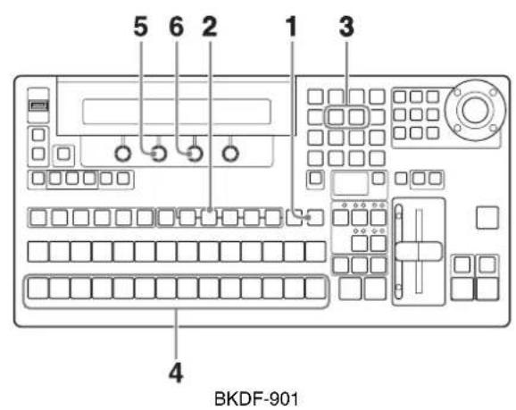
1 When using the BKDF-901: If the SHIFT button of the DME/SETUP block is not lit, press it to light it.
When using the BKDF-902: Skip to step 2.
2 Press the INPUT button.
A settings sub menu of the Input sub menu appears in the display panel.
3 Press the ◀ or ▷ button in the numeric keypad until the Setting 1 sub menu appears.
"Setting1" appears in the sub menu title display area. If it is already displayed there, you can skip this step.


4 When using the BKDF-901: Press the PRESET selection button that selects the input you want to set.
If you want to set an input that has been assigned by using the SHIFT button (see page 76), press the SHIFT button before pressing the PRESET selection button.
When using the BKDF-902: Press the M/E bus B selection button that selects the input you want to set.
If you want to set an input that has been assigned by using the SHIFT button (see page 76), press the SHIFT button before pressing the M/E bus B selection button.
5 Enable frame synchronizer memory by rotating the F2 knob to select "On".
Note
If you select "Off", frame synchronizer memory is disabled (and the setting in step 6 is disabled).
6 Rotate the F3 knob and select "Live".
The frame synchronizer is enabled for input video signals.
Note
All settings other than “Live” are settings for capture of still images from input signals. For details, see “To capture still images from input signals” (page 80).
7 Repeat steps 4 to 6 as required to set other inputs.
To capture still images from input signals
In step 6 of “To enable frame synchronizers” (page 79), select an item other than “Live” and make the settings for still image capture and output. You can select the following settings.
Frm: Capture a frame image from the input signal
Even: Capture a field image (even field) from the input signal
Odd: Capture a field image (odd field) from the input signal
Notes
- A frame or field image is captured as soon as you select one of Frm, Even, or Odd.
- When capturing still images from an up-converted input signal (see page 81), only Frm can be selected.
- To store a still image captured from input signals, you must first output it to program output. For details about how to store still images, see page 118.
- When you download a still image to the memory of an input (see page 118), the frame synchronizer mode of that input is set automatically to On. At the same time, the output signal is set automatically to Frm. Change the setting as required after downloading the still image.
Making up-convert input settings
The optional BKDF-910 and BKDF-911 input expansion boards feature internal up-converters. When these boards are installed and the switcher's video format is set to HD signals (see page 71), you can select the conversion mode used by the up-converters to up-convert SD format video input signals to HD format video input signals.
For more information about the BKDF-910 and BKDF-911, see page 31. For information about how to install them, see page 39.
Notes
- The up-converters can be set only when the switcher's video format (see page 71) is set to HD signals.
- When the video format is switched from HD to SD, the up-converter settings of each input channel are set automatically to OFF. Make the up-converter settings again when you return the video format to HD.
- The following table lists the input channels on the input expansion boards that are equipped with up-converters.
| Input expansion board Inputs with up-converters |
| BKDF-910 4 SDI Input Board SDI IN1 and SDI IN2 |
| BKDF-911 2 SD Video Input Board All inputs |
For more information about the channel numbers for channels with up-converters, and how they are displayed in the input display, see page 39.
- Different up-converter settings can be specified for each input channel. However, on the BKDF-910 it is not possible to turn individual channels OFF. When the up-converter on one channel is turned OFF, the other channel is turned OFF automatically.
- On the BKDF-911, up-converters cannot be turned OFF when the video format is HD.
- Up-converting a finely detailed image (such as spray from a fountain) may result in some blurriness.
- The switcher's standard input connectors (SDI IN1 to SDI IN8) are not equipped with up-converters.


1 When using the BKDF-901: If the SHIFT button of the DME/SETUP block is not lit, press it to light it.
When using the BKDF-902: Skip to step 2.
2 Press the INPUT button.
A settings sub menu of the Input sub menu appears in the display panel.
3 Press the ◀ or ▷ button in the numeric keypad until the Setting 2 sub menu appears.
"Setting2" appears in the sub menu title display area. If it is already displayed there, you can skip this step.

flowchart
graph TD
    A["Setting2\nF=Compst UC=Off L=Betacam"] --> B["F1"]
    A --> C["F2"]
    A --> D["F3"]
    A --> E["F4"]
4 When using the BKDF-901: Press the PRESET selection button that selects the input you want to set.
If you want to set an input that has been assigned by using the SHIFT button (see page 76), press the SHIFT button before pressing the PRESET selection button.
When using the BKDF-902: Press the M/E bus B selection button that selects the input you want to set.
If you want to set an input that has been assigned by using the SHIFT button (see page 76), press the SHIFT button before pressing the M/E bus B selection button.
5 Rotate the F3 knob to select the conversion mode.
4:3: Input with 4:3 aspect ratio (add black to left and right sides of picture)
4:3BGS: Input with 4:3 aspect ratio (Add still images to the left and right sides of picture. The two sides of a downloaded still image file (HDTV size) are added to the video input.)
SQ: Input as squeeze video
LB: Input as letterbox video
Off: Do not up-convert
Notes
- For information about how to download still images from still image storage memory to the memory of switcher inputs, see page 118.
- When you select 4:3BGS, download an HDTV size still image. The left and right sides of the picture will not be displayed normally if no image is downloaded or if the downloaded image is a SDTV size image.
Specifying the signal type of analog input signals
When you are using the optional BKDF-911 2 SD Video Input Board, specify the signal type of the analog signals that will be input to the board.
For more information about the BKDF-911, see page 31. For information about how to install it, see page 39.
Note
Regardless of this setting, the only signals that can be input to the COMP connector of the BKDF-911 are SD analog composite signals.

BKDF-902
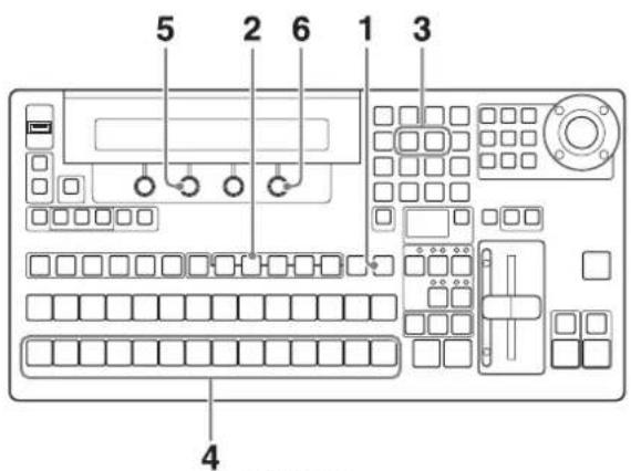
BKDF-901
1 When using the BKDF-901: If the SHIFT button in the DME/SETUP block is not lit, press it to light it.
When using the BKDF-902: Skip to step 2.
2 Press the INPUT button.

A settings sub menu of the Input sub menu appears in the display panel.
3 Press the ◀ or ▷ button in the numeric keypad until the Setting 2 sub menu appears.
"Setting2" appears in the sub menu title display area. If it is already displayed there, you can skip this step.

4 When using the BKDF-901: Press the PRESET selection button that selects the analog input you want to set.
If you want to set an analog input that has been assigned by using the SHIFT button (see page 76), press the SHIFT button before pressing the PRESET selection button.
When using the BKDF-902: Press the M/E bus B selection button that selects the analog input that you want to set.
If you want to set an analog input that has been assigned by using the SHIFT button (see page 76), press the SHIFT button before pressing the M/E bus B selection button.
5 Rotate the F2 knob to select the type of signal that will be input.
Compst: Analog composite signal
Y/CB/CR: Analog component (color difference) signal
Notes
- Analog HD component signals cannot be input.
- The following table shows the input signals and the numbers assigned to each input channel (see page 39).
| Setting of step 5 | Name of BKDF-911 connector | Input signal | BKDF-911 installation position and channel number | |||
| Lower tray Upper tray | ||||||
| Left Center Left | Center | |||||
| Compst | COMP/Y Composite signal | IN09 IN13 IN17 IN21 | ||||
| R-Ya) | - | - | - | - | ||
| B-Ya) | - | - | - | - | ||
| COMP Composite signal | IN10 IN14 IN18 IN22 | |||||
| Y/CB/CR | COMP/Y Luminance (Y) signal | IN09 IN13 IN17 IN21 | ||||
| B-Y Color | difference (B-Y) signal | |||||
| R-Y Color | difference (R-Y) signal | |||||
| COMP Composite signal | IN10 IN14 IN18 IN22 | |||||
a) Connector is disabled
6 If you selected Y/CB/CR in step 5, rotate the F4 knob to select the level of the component input signals.
Betacam: Betacam level
SMPTE: SMPTE level
Note
Settings of step 6 can be available only when the switcher's video format (see page 71) is set to 525/59, 720/59, or 1080/59.
Specifying the signal type of DVI input signals
When you are using the optional BKDF-912 2 DVI Input Board, specify the picture size and aspect ratio conversion modes for the DVI signals that will be input to the board.
For more information about the BKDF-912, see page 31. For information about how to install it, see page 39.
Note
Depending on the video format setting of this switcher (page 71), select the DVI input signal resolution from the values in the following table. If you specify a resolution other than the values shown in the table, images may be unable to be reproduced normally.
| Video format setting DVI input signal resolution | |
| 525/59 or 625/50 VGA (640 × 480) | SVGA (800 × 600)XGA (1024 × 768) |
| 720/50 or 720/59 XGA (1024 × 768) | SXGA (1280 × 1024)WXGA (1280 × 768) |
| 1080/50 or 1080/59 XGA (1024 × 768) | SXGA (1280 × 1024)WXGA (1280 × 768)UXGA (1600 × 1200)WSXGA (1680 × 1050)WUXGA (1920 × 1200) |


BKDF-902

BKDF-901
1 When using the BKDF-901: If the SHIFT button of the DME/SETUP block is not lit, press it to light it.
When using the BKDF-902: Skip to step 2.
2 Press the INPUT button.
A settings sub menu of the Input sub menu appears in the display panel.
3 Press the ◀ or ▷ button in the numeric keypad until the DVI sub menu appears.
“DVI” appears in the sub menu title display area. If it is already displayed there, you can skip this step.
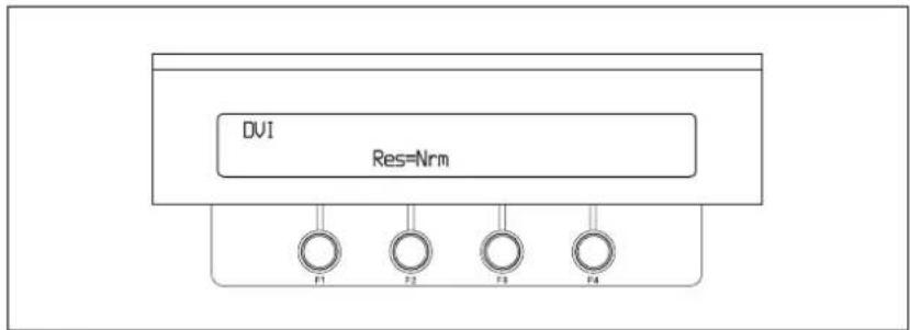
4 When using the BKDF-901: Press the PRESET selection button that selects the DVI input you want to set. If you want to set a DVI input that has been assigned by using the SHIFT button (see page 76), press the SHIFT button before pressing the PRESET selection button.
When using the BKDF-902: Press the M/E bus B selection button that selects the DVI input that you want to set. If you want to set a DVI input that has been assigned by using the SHIFT button (see page 76), press the SHIFT button before pressing the M/E bus B selection button.
5 Rotate the F2 knob to select the picture size and aspect ratio conversion modes.
Normal: Do not convert either the picture size or aspect ratio.
Zoom: Expand the screen size to match the horizontal width of a 16:9 aspect ratio picture (vertical and horizontal zoom ratios are the same).
Full: Modify the picture size to match a 16:9 aspect ratio picture, so that all areas of the picture are displayed (the vertical and horizontal modification ratios are different).
Application of conversion settings of step 5 to identical picture

Note
If you select Normal when the switcher's video format is set to HD signals (see page 71), black is added at the top, bottom, left, and right of the picture. However, the top and bottom of the picture are cut if the input video is UXGA or WUXGA. If you select Zoom, the top and bottom are cut for all types of video (the amount cut depends on the picture size).
Adjusting input signals
Use the following procedure to adjust the various levels of video input signals.


1 When using the BKDF-901: If the SHIFT button of the DME/SETUP block is not lit, press it to light it.
When using the BKDF-902: Skip to step 2.
2 Press the INPUT button.
A settings sub menu of the Input sub menu appears in the display panel.
3 Press the ◀ or ▷ button in the numeric keypad until the Input Process1 or Input Process2 sub menu appears, depending on what you want to adjust.
"Input Process1" or "Input Process2" appears in the sub menu title display area. If the title you want is already displayed there, you can skip this step.
Example with "Input Process1" displayed:

4 When using the BKDF-901: Press the PRESET selection button that selects the input you want to set.
If you want to set an input that has been assigned by using the SHIFT button (see page 76), press the SHIFT button before pressing the PRESET selection button.
When using the BKDF-902: Press the M/E bus B selection button or the PRESET bus selection button that selects the input you want to set. If you want to set an input that has been assigned by using the SHIFT button (see page 76), press the SHIFT button before pressing the M/E bus B selection button or the PRESET bus selection button.
5 Rotate the F1 to F4 knobs to make the settings.
The signal characteristics set by the sub menus and the correspondence between knobs and parameters are as follows.
Input Process1 sub menu
| Knob | Parameter | Description | Setting range |
| F1 WClp Set the white clip | level 50.0 to 109.0 | ||
| F2 BClp Set the black clip | level -7.0 to 50.0 | ||
| F3 LGN Set the luminance | signal gain 0.00 to 200.00 | ||
| F4 Set Adjust the black signal level 0.0 to 100.0 | |||
Input Process2 sub menu
| Knob | Parameter | Description | Setting range |
| F1 | CCIp | Set the chroma signal clip level | 50.0 to 111.0 |
| F2 | CGN | Set the chroma signal gain | 0.00 to 200.00 |
| F3 | H Phase Trim^a) | Adjust the horizontal phase^a) | -4 to 4 |
| F4 Hue Adjust the hue 0.0 | to 359.5 | ||
a) Valid only when the BKDF-911 2 SD Video Input Board is installed
Making Settings Related to Output Signals
Selecting output signals for AUX output
Including the four standard video outputs (PGM1/2 and AUX1/2), you can use up to 12 video outputs by adding option boards.
Tips
You can assign input signals, internally processed signals, or program outputs to the output connectors of AUX1, AUX2, and output expansion boards (SDI, SD VIDEO, and DVI).
You can also assign multi-view outputs to those output connectors when you install the optional BKDF-950 Multi Viewer Board in the processor unit.
When the input is SDI signals (HD-SDI or SD-SDI), you can select whether to output ancillary data such as multiplexed audio and timecode.
Note
The signals output from the PGM1 and PGM2 outputs cannot be changed.

BKDF-902

BKDF-901
1 When using the BKDF-901: Press the AUX button.
When using the BKDF-902: Press one of the AUX1 to AUX10 buttons.
Note
The AUX3 to AUX10 buttons that correspond to channels on installed output expansion boards are enabled (buttons with no corresponding channels are not enabled). When you are using the BKDF-961 and BKDF-962 output expansion boards, some output channel numbers are invalid. For details, see page 39.
The Aux (AUX output assignments) sub menu appears in the display panel.

2 When using the BKDF-901: Rotate the F1 knob to select an output, from AUX1 to AUX10.
When using the BKDF-902: Skip to step 3.
Note
AUX3 to AUX10 are available only when optional expansion boards are installed. For details, see page 39.
3 Rotate the F2 knob to select the signal to assign.
BLK: Black signal
IN01 to IN24: Video inputs
STL01 to STL04: Still images 1 to 4 stored in the processor unit
MAT1 to MAT4: Color matte signals 1 to 4
MV1 and MV2: Multi-view output
PGM: Program output
PVW: Preview output
CLN: Clean output (program output without downstream key)
KOut: Key output
MPGM: M/E output (when using the BKDF-902)
MPVW: M/E preview output (when using the BKDF-902)
Tips
- If, after step 3, you rotate the F3 knob to set the Inh (Inhibit) item to On, the AUX output signal cannot be changed from the control panel. Control is possible only by remote control from an optional AUX BUS remote controller.
- For more information about screen settings for multi-view output, see page 96.
Notes
- When optional input expansion boards have been installed, signal names corresponding to the installation positions appear for IN09 to IN24. For details, see page 39.
- When the display names of input signals or internal signals have been changed (see page 74), the user-specified names appear.
4 When HD-SDI or SD-SDI signals are being input, rotate the F4 knob to select whether to output ancillary data (audio, timecode, etc.).
Off: Do not output ancillary data in the input signals.
On: Output ancillary data in the input signals.
Note
To output ancillary data, disable the frame synchronizers (page 79). It will also be disabled to use a function which captures still images from input video signals (page 80).
Making down-convert output settings
The optional BKDF-960 and BKDF-961 output expansion boards feature internal down-converters. When these boards are installed and the switcher's video format is set to HD signals (see page 71), you can select the conversion mode used by the down-converters to down-convert HD format video signals to SD format video output signals.
For more information about the BKDF-960 and BKDF-961, see page 31. For information about how to install them, see page 39.
Notes
- The down-converters can be set only when the switcher's video format (see page 71) is set to HD signals.
- When the video format is switched from HD to SD, the down-converter settings of each input channel are set automatically to OFF. Make the down-converter settings again when you return the video format to HD.
- The following table lists the output channels on the output expansion boards that are equipped with down-converters.
| Output expansion board Outputs with down-converters | |
| BKDF-960 4 SDI Output Board SDI OUT1 | and SDI OUT2 |
| BKDF-961 2 SD Video Output Board All outputs | |
For more information about the channel numbers for channels with down-converters, and how they are displayed in the output display, see page 39.
- Different down-converter settings can be specified for each output channel. However, on the BKDF-961 it is not possible to disable down-converters when the video format is HD.
- The switcher's standard output connectors (PGM1, PGM2, AUX1, AUX2) are not equipped with down-converters.

BKDF-902

BKDF-901

1 When using the BKDF-901: Press the AUX button.
When using the BKDF-902: Among the AUX03 to AUX10 buttons, press the button that selects the AUX output that you want to set.
The Aux (AUX output assignment settings) sub menu appears in the display panel.
2 Press the ▷ button in the numeric keypad until the Output (output detailed settings) sub menu appears.
"Output" appears in the sub menu title display area. If it is already displayed there, you can skip this step.

3 When using the BKDF-901: Rotate the F1 knob to select the item that selects the AUX output that you want to set, from among AUX03 to AUX10.
When using the BKDF-902: Skip to step 4.
Note
AUX1 and AUX2 are not provided with down-converting capability.
4 Rotate the F3 knob to select the conversion mode.
4:3: Output with 4:3 aspect ratio (edge cropped output)
SQ: Output as squeeze video
LB: Output as letterbox video
Off: Do not down-convert
Specifying the signal type of analog output signals
When you are using the optional BKDF-961 2 SD Video Output Board, specify the signal type of the analog signals that will be output from the board.
For more information about the BKDF-961, see page 31. For information about how to install it, see page 39.
Note
Regardless of this setting, signals output from the COMP connector of the BKDF-961 are always SD analog composite signals.

BKDF-902

BKDF-901
1 When using the BKDF-901: Press the AUX button.
When using the BKDF-902: From among the buttons AUX03 to AUX10, press one to which analog output has been assigned.
The Aux (AUX output assignment settings) sub menu appears in the display panel.
2 Press the ◀ or ▷ button in the numeric keypad until the Output (output detailed settings) sub menu appears.
"Output" appears in the sub menu title display area. If it is already displayed there, you can skip this step.

3 When using the BKDF-901: Rotate the F1 knob to select an item from among AUX03 to AUX10 to which analog output has been assigned.
When using the BKDF-902: Skip to step 4.
4 Rotate the F2 knob to select the output signal type.
Compst: Analog composite signal
Y/CB/CR: Analog component (color difference) signal
GBR/wSync: Analog component (RGB) signal (sync signal multiplexed into G signal)
Notes
- Analog HD component signals cannot be output.
- The following table lists the signals to be connected and the number assigned to each input channel (see page 39).

| Setting of step 4 | Name of BKDF-961 connector | Output signal BKDF-961 installation position and channel number | |
| Compst COMP | P/Y Composite signal AUX03 AUX07 | ||
| B-Y a) | - | - | |
| R-Y a) | - | - | |
| COMP Composite signal AUX04 AUX08 | |||
| Y-CB/CR COMP | Y (luminance) signal AUX03 AUX07 | ||
| B-Y Color difference (B-Y) signal | |||
| R-Y Color difference (R-Y) signal | |||
| COMP Composite signal AUX04 AUX08 | |||
| GBR/wSync COMP | Y G (green) signal (with multiplexed sync signal) | AUX03 AUX07 | |
| B-Y B (blue) signal | |||
| R-Y R (red) signal | |||
| COMP Composite signal AUX04 AUX08 | |||
a) Connector is disabled
5 If you selected Y/CB/CR in step 4, rotate the F4 knob to select the level of the component output signals.
Betacam: Betacam level
SMPTE: SMPTE level
Note
Settings of step 5 can be available only when the switcher's video format (see page 71) is set to 525/59, 720/59, or 1080/59.
Specifying the signal type of DVI output signals
When you are using the optional BKDF-962 2 DVI Output Board, specify the signal type of the DVI signals that will be output from the board.
For more information about the BKDF-962, see page 31. For information about how to install it, see page 39.

BKDF-902

BKDF-901
1 When using the BKDF-901: Press the AUX button.
When using the BKDF-902: From among the buttons AUX03 to AUX10, press one to which DVI output has been assigned.
The Aux (AUX output assignment settings) sub menu appears
2 Press the ◀ or ▷ button in the numeric keypad until the DVI (DVI output settings) sub menu appears.
“DVI” appears in the sub menu title display area. If it is already displayed there, you can skip this step.

3 When using the BKDF-901: Rotate the F1 knob to select an item from among AUX03 to AUX10 to which DVI output has been assigned.
When using the BKDF-902: Skip to step 4.
4 Rotate the F2 knob to select the output signal type from the types listed in the following table.
| Parameter Output signal Video format settingYes: Can be selectedNo: Cannot be selected(the parameter does not appear) | |||
| SVGA SVGA signal(800 x 600) | 525/59 or625/50 | 720/50 or720/59 | 1080/50 or1080/59 |
| YesNoNo | |||

| Parameter Output signal Video | eo format settingYes: Can be selectedNo: Cannot be selected(the parameter does not appear) | |||
| 525/59 or 625/50 | 720/50 or 720/59 | 1080/50 or 1080/59 | ||
| WXGA WXGA signal(1280 x 768) | No Yes No | |||
| SXGA SXGA signal(1280 x 1024) | No Yes Yes | |||
| UXGA UXGA signal(1600 x 1200) | No No | Yesa) | ||
| WSXGA WSKGA signal(1680 x 1050) | No No Yes | |||
| HDTV Full HDTV size(1920 x 1080)signal | No No Yes | |||
| WUXGA WUXGA signal(1920 x 1200) | No No | Yesa) | ||
a) Only digital signals are output. Analog signals are not output.
Notes
- Depending on the video format setting (see page 71), some parameters cannot be selected.
- If you select HDTV, color difference component signals (Y / P_b / P_r) are output from the analog signal output connectors of the BKDF-962. If you select another parameter (excluding UXGA and WUXGA), RGB signals are output.
5 If you selected SXGA or UXGA in step 4, rotate the F3 knob to select the output mode.
4:3: Cut both sides of the picture and output with aspect ratio 4:3 (edge crop output).
LB: Output letterbox video.
Note
When 4:3 is selected, the amount cut at the sides of the picture differs between SXGA and UXGA.
6 Rotate the F4 knob to specify the system format of the output destination.
50Hz: When the system format of the output destination is 50 Hz.
60Hz: When the system format of the output destination is 60 Hz.
Note
50Hz can be selected only when the switcher's video format (see page 71) is set to 625/50, 720/50, or 1080/50. This setting affects only digital signals output from the BKDF-962.
Making multi-view output settings
The multi-view function is available when you install the optional BKDF-950 Multi Viewer Board in the processor unit. By assigning multi-view output to an AUX connector and connecting a video monitor, you can check video on a monitor screen divided into up to 16 partitions, including input video, program output video, and preview video.

Multi-view screen example (10 partitions)
You can install up to two BKDF-950 boards, and set output patterns for each board in both the MV1 Window and MV2 Window sub menus.
You also change the size and position of child window titles, and add frames to indicate that the signal assigned to a child window is program or preview output or a component element of program or preview output (the currently selected input, a key signal, and so on).
For details about the BKDF-950 and information about how to install it, see page 46.
Note
The MV1 Window and MV2 Window sub menus cannot be set if the BKDF-950 board is not installed.
To specify the partition type and assign output video to child windows

BKDF-902

BKDF-901
1 When using the BKDF-901: If the SHIFT button of the DME/SETUP block is not lit, press it to light it.
When using the BKDF-902: Skip to step 2.
2 Press the MV button.
A settings sub menu of the MV (multi-view output settings) sub menu appears in the display panel.

3 Press the ◀ or ▷ button in the numeric keypad until the MV1 Window or MV2 Window sub menu appears.
As shown in the following table, the sub menu title in the display panel indicates the BKDF-950 board targeted by this procedure. If the title that you want is already displayed there, you can skip this step.
| Name displayed in sub menu title display area | Description |
| MV1 Window Select to make settings for the BKDF-950 connected to MV1 socket. | |
| MV2 Window Select to make settings for the BKDF-950 connected to MV2 socket. | |
Example with MV1 Window displayed:

Note
Both the MV1 Window and MV2 Window sub menus appear when a BKDF-950 is installed in either socket, but settings made in a sub menu that corresponds to an empty socket (one with no BKDF-950 installed) are ignored.
4 Rotate the F1 knob to select the number of multi-view partitions.
You can select from 4, 10, or 16.
5 Rotate the F2 knob to select the number of the child window that you want to set.
Depending on the number of partitions selected in step 4, select a number from 1 to 16.
For more information about partitions in the multi-view screen and child window numbers, see page 99.
6 Rotate the F3 knob to select the video output to the child window.
BLK: Black signal
IN01 to IN24: Video inputs
STL1 to STL4: Still images 1 to 4 stored in the processor unit
MAT1 to MAT4: Color matte signals 1 to 4.
PGM: Program output
PVW: Preview output
CLN: Clean output (program output without downstream key)
KOut: Key signal
MPGM: M/E output (when using the BKDF-902)
MPVW: M/E preview output (when using the BKDF-902)
Notes
- When optional input expansion boards have been installed, signal names corresponding to the installation positions appear for IN09 to IN24. For details, see page 39.
- When the display names of input signals or internal signals have been changed (see page 74), the user-specified names appear.
7 Repeat steps 5 and 6 to set other child windows.
8 Rotate the F4 knob to turn display of the child window titles on or off.
On: Display titles. Off: Do not display titles.
Notes
- The settings made in step 8 are reflected in all child windows. It is not possible to make title display settings separately for individual windows.
- The display of child window titles is turned off automatically when you change the multi-view window partition type. If you want to display titles, turn title display on again.
Multi-view window partition types and child window numbers
TYPE4
| 1 | 2 |
| 3 | 4 |
TYPE10
| 1 | 2 | ||
| 3 | 4 | 5 | 6 |
| 7 | 8 | 9 | 10 |
TYPE16
| 1 | 2 | 3 | 4 |
| 5 | 6 | 7 | 8 |
| 9 | 10 | 11 | 12 |
| 13 | 14 | 15 | 16 |
To adjust the display positions and sizes of child window titles
1 Carry out steps 1 to 6 of the procedure in “Changing signal display names” (page 74) to load a list file output by the control panel (dfs900.ini) into a computer.
2 Use Notepad or another text editor to edit the parameter values (the values after the equals signs) in the [MVParam] section of the dfs900.ini file.
| Parameter | Description Setting values | |
| LargeOffsetV | Specifies the vertical display position in large child windows. | 0 to 50 |
| LargeOffsetH | Specifies the horizontal display position in large child windows. | 0 to 50 |
| LargeWidth Sp | Specifies the display width in large child windows. | 0 to 50 |

| Parameter | Description Setting values | |
| LargeHeight S | Specifies the height of characters in large child windows. | 0 to 50 |
| SmallOffsetV | Specifies the vertical display position in small child windows. | 0 to 25 |
| SmallOffsetH | Specifies the horizontal display position in small child windows. | 0 to 25 |
| SmallWidth S | Specifies the display width in small child windows. | 0 to 25 |
| SmallHeight S | Specifies the height in characters in small child windows. | 0 to 25 |
| HalfMatte Spec | Specifies whether to add a background (half matte black rectangle) behind signal name displays. | ON: Add backgroundOFF: Do not add background |
Note
The settings made here are applied to all child windows of the same size. It is not possible to specify display positions for individual child windows.
Title display positions and parameter values

flowchart
graph TD
    A["Title display"] --> B["Large (Small) OffsetH (horizontal position)"]
    A --> C["Large (Small) Width (display width)"]
    A --> D["Large (Small) Height (character height)"]
    A --> E["Large (Small) OffsetV (vertical position)"]
3 After editing the file parameters, save the file back to the USB flash drive (overwriting the old file), and then insert the flash drive into the USB MEMORY connector again.
4 Carry out steps 2 to 4 of the procedure in "Changing signal display names" to display the Signal sub menu, and then hold the F4 knob down for one second or longer.
The updated file is loaded into the switcher.
Note
The above operations alone do not cause child window titles to be displayed. Continue by carrying out step 5 below.
5 Carry out steps 1 to 3 of the procedure in "To specify the partition type and assign output video to child windows" (page 97) to display the MV1 or MV2 sub menu, and then carry out step 8 to turn the display of child window titles on.
To add frames to child windows
You can add frames to child windows to indicate that the signal assigned to a child window is program or preview output or a component element of program or preview output (the currently selected input, a key signal, and so on).
Tips
- The factory default frame color settings are as follows.
| Child window output Frame color | |
| Program output, and components of program output Red | |
| Preview output, and components of preview output Green |
- When program output and preview output share the same component elements, the frame color for program output takes priority.
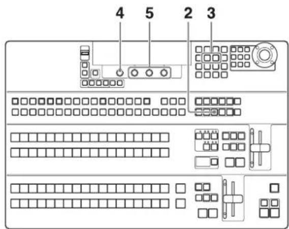
BKDF-902

BKDF-901
1 When using the BKDF-901: If the SHIFT button of the DME/SETUP block is not lit, press it to light it.
When using the BKDF-902: Skip to step 2.
2 Press the MV button.
A settings sub menu of the MV (multi-view output settings) sub menu appears in the display panel.
3 Press the ◀ or ▷ button in the numeric keypad until one of the following status sub menus appears, for one of the types of windows to which frames can be added.
If the sub menu that you want is already displayed, you can skip this step.
| Name displayed in sub menu title display area | Description |
| MV1 OA Tally Among the multi-view child windows displayed by a BKDF-950 connected to MV1 socket, display a frame around windows that display the current On Air program output, or component elements of that output. | |

| Name displayed in sub menu title display area | Description |
| MV1 Next Tally Among the multi-view child windows displayed by a BKDF-950 connected to MV1 socket, display a frame around windows that display the video to be sent to program output next, or component elements of that output. | |
| MV2 OA Tally Among the multi-view child windows displayed by a BKDF-950 connected to MV2 socket, display a frame around windows that display the current On Air program output, or component elements of that output. | |
| MV2 Next Tally Among the multi-view child windows displayed by a BKDF-950 connected to MV2 socket, display a frame around windows that display the video to be sent to program output next, or component elements of that output. | |
Example with MV1 OA Tally displayed:
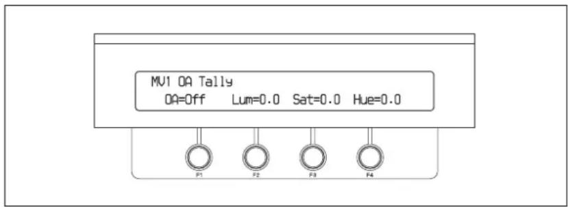
Example with MV1 Next Tally displayed:
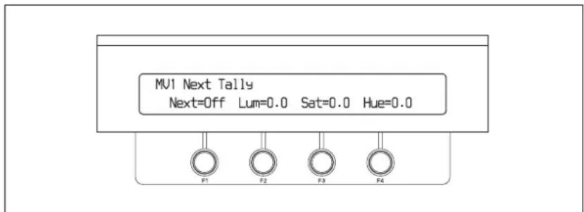
4 Rotate the F1 knob to specify whether to add a frame.
Off: Do not add a frame.
On: Add a frame.
5 Rotate F2, F3, and F4 knobs to specify the color and other properties of the frame.
The correspondence between knobs and parameters is as follows.
| Knob | Parameter | Description | Setting range |
| F2 Luminance | Luminance of the frame 0.0 to 108.6 | ||
| F3 Saturation | Saturation of the frame 0.0 to 100 | ||
| F4 Hue Hue | of the frame 0.0 to 359.5 |
Enabling the DSK preview function
When downstream keys are off, you can display them in the preview window (DSK preview function).
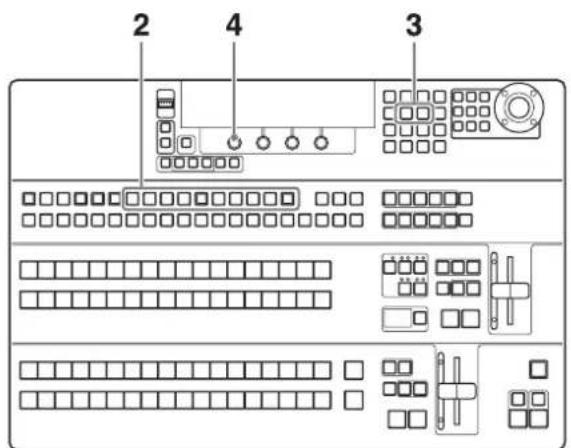
BKDF-902

BKDF-901
1 When using the BKDF-901: If the SHIFT button of the DME/SETUP block is not lit, press it to light it.
When using the BKDF-902: Skip to step 2.
2 When using the BKDF-901: Press the AUX button.
When using the BKDF-902: Press on of the AUX1 to AUX10 buttons.
Note
When optional expansion boards are not installed, the AUX3 to AUX10 buttons are disabled.
A settings sub menu of the Aux sub menu appears in the display panel.
3 Press the ▷ button in the numeric keypad until the Setup >Output >Other sub menu appears.
“Other” appears in the sub menu title display area. If it is already displayed there, you can skip this step.

4 Rotate the F1 knob to turn the DSK preview function on or off.
On: Display downstream keys in the preview window only when downstream keys are off.
Off: Do not display downstream keys in the preview window.
Making Other Settings
Specifying the timing of video switching
You can specify whether to switch video signals on odd fields, even fields, or any field.


BKDF-902

BKDF-901
1 When using the BKDF-901: If the SHIFT button of the DME/SETUP block is not lit, press it to light it.
When using the BKDF-902: Skip to step 2.
2 Press the SYSTEM button.
A settings sub menu of the System sub menu appears in the display panel.
3 Press the ◀ or ▷ button in the numeric keypad until the Other sub menu appears.
“Other” appears in the sub menu title display area. If it is already displayed there, you can skip this step.
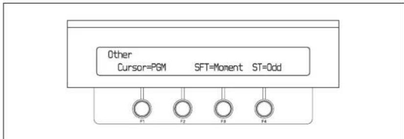
4 Rotate the F4 knob to select the timing of video switching.
Odd: Switch video on odd fields.
Even: Switch video on even fields.
Any: Switch video on any field.
Note
This setting is ignored when the video format setting is 720/50 or 720/59 (see page 71).
Selecting the operating mode of the SHIFT buttons
Use the following procedure to select the operating mode of the SHIFT buttons of the cross-point bus block.

BKDF-902
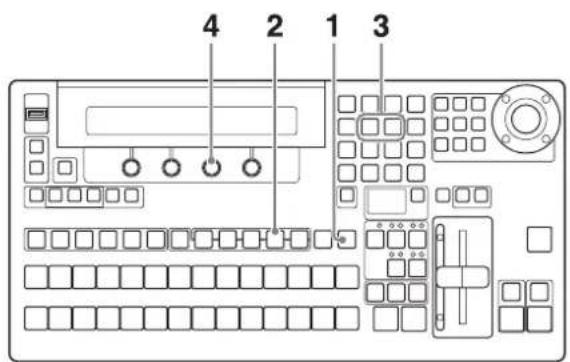
BKDF-901
1 When using the BKDF-901: If the SHIFT button of the DME/SETUP block is not lit, press it to light it.
When using the BKDF-902: Skip to step 2.
2 Press the SYSTEM button.
A settings sub menu of the System sub menu appears in the display panel.
3 Press the ◀ or ▷ button in the numeric keypad until the Other sub menu appears.
“Other” appears in the sub menu title display area. If it is already displayed there, you can skip this step.

flowchart
graph TD
    A["Other Cursor=PGM"] --> B["F1"]
    A --> C["F2"]
    A --> D["F3"]
    A --> E["F4"]
    A --> F["SFT=Moment"]
    A --> G["ST=Odd"]
4 Rotate the F3 knob to select the timing of video switching.
Moment: Selects the SHIFT side functions assigned to buttons as long as a SHIFT button is held down.
Toggle: Each press of a SHIFT button toggles between selecting the SHIFT side and non-SHIFT side functions assigned to buttons.
Setting the Date and Time
Use the following procedure to set the date and time of the switcher's internal clock.
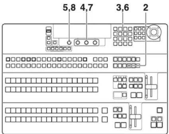
1 When using the BKDF-901: If the SHIFT button of the DME/SETUP block is not lit, press it to light it.
When using the BKDF-902: Skip to step 2.
2 Press the SYSTEM button.
A settings sub menu of the System sub menu appears in the display panel.
3 Press the ◀ or ▷ button in the numeric keypad until the Date Adj. (set date) sub menu appears.
“Date Adj.” appears in the sub menu title display area. If it is already displayed there, you can skip this step.

4 Rotate the F2, F3, and F4 knobs to set the year, month, and day.
The correspondence between knobs and parameters is as follows.
| Knob | Parameter | Description | Setting range |
| F2 Y Year 2000 to 2100 | |||
| F3 M Month 1 to 12 | |||
| F4 D Day 1 to 31 | |||
5 Hold the F1 knob down for one second or longer.
The date is set.

6 Press the ▷ button once to display the Time Adj. (set time) sub menu. "Time Adj." appears in the sub menu title display area.

7 Rotate the F2, F3, and F4 knobs to set the hour, minute, and second. The correspondence between knobs and parameters is as follows.
| Knob Parameter | Description Setting range | |
| F2 H Hour 0 to 23 | ||
| F3 M Minute 0 to 59 | ||
| F4 S Second 0 to 59 |
8 Hold the F1 knob down for one second or longer. The time is set.
Basic Operations
Chapter
4
Selecting Backgrounds
The output from the PGM1 and PGM2 connectors is called the “program output video”. You can check it on the program monitor and in the multi-view screen.
For more information about the multi-view screen, see "Making multi-view output settings" (page 96).
The rearmost video in program output video is the background.

Program output video
To select a background
When using the BKDF-901: Use the PROGRAM selection buttons in the cross-point bus block. From among these buttons, press the button to which the video that you want has been assigned.
When using the BKDF-902: Use the M/E bus A selection buttons in the M/E cross-point bus block, and the PROGRAM bus selection buttons and the M/E button in the PROGRAM/PRESET cross-point bus block. From among these buttons, press the button to which the video that you want has been assigned. Press the M/E button to select the video which was selected in the M/E cross-point bus block.
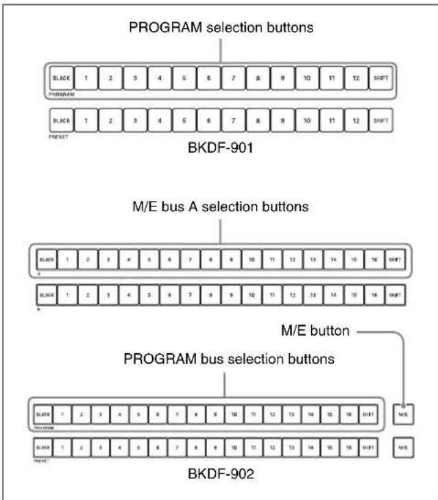
The pressed button lights in red. This indicates that the selected video is being output as the program video. In the multi-view screen, the current program output video is surrounded by a frame. When the switcher is shipped from the factory, the color of the frame is set to red.
To select the background that appears after a transition
When using the BKDF-901: Use the PRESET selection buttons in the cross-point bus block. From among these buttons, press the button to which the video that you want has been assigned.
When using the BKDF-902: Use the M/E bus B selection buttons in the M/E cross-point bus block, and the PRESET bus selection buttons and the M/E button in the PROGRAM/PRESET cross-point bus block. From among these buttons, press the button to which the video that you want has been assigned. Press the M/E button to select the video which was selected in the M/E cross-point bus block.
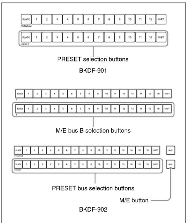
The pressed button lights in green. This indicates that the selected video is not being output from a PGM connector. In the multi-view screen, the preset video is surrounded by a frame. When the switcher is shipped from the factory, the color of the frame is set to green.
Switching Backgrounds
A replacement of one or more of the video elements that make up the current program output by another video element is called a “transition”.
Video elements include the background and keys 1 to 4. A transition can involve changes in one element or simultaneous changes in a number of elements.
There are two main types of transitions.
- Transitions in which the next video appears instantly. This type of transition is called a “cut”.
• Transitions in which the next video appears gradually over a specified time through the application of an effect. Two of the most commonly used effect types are mixes and wipes.
This section explains how to switch the background.
Cutting to a New Background
Basic cut operations
There are two ways to cut to a new background.
- Cut directly to the next background by pressing a cross-point selection button.
- Check the next background in the preview screen, and then press the CUT button.
The figure below shows the flow of cut operations.

flowchart
graph TD
    A["Select the program output video."] --> B["Cut to other video. Select the video"]
    B --> C["video that you want to appear next."]
    C --> D["Press the CUT button."]
Cutting directly with the cross-point selection buttons
If you simply want to switch to other video inputs, you can press the cross-point selection buttons to which those inputs have been assigned, pressing one button after another.
Tip
By installing the optional BKDF-950 Multi Viewer Board, you can check program video, preview video, and multiple video inputs at the same time on a video monitor connected to the processor unit. This is very convenient when you select video signals.


For details, see "Making multi-view output settings" (page 96).
Cutting with the CUT button after checking the next video in the preview screen
Use the CUT button to cut instantly after checking the video in the preview screen.
When using the BKDF-901

1 In the transition block, press the BKGD next transition selection button, lighting it.
2 In the cross-point bus block, press a PROGRAM selection button to select the video that appears before the cut.
The pressed button lights in red, and the selected video becomes the program output video.
3 Press a PRESET selection button to select the video that appears after the cut.
The pressed button lights in green, and the selected video appears in the preview screen.
4 Press the CUT button.
The program output and preview output video are switched instantly. The colors of the buttons in the cross-point block change to reflect the switch.
Example: When PROGRAM selection button 1 and PRESET selection button 4 are selected
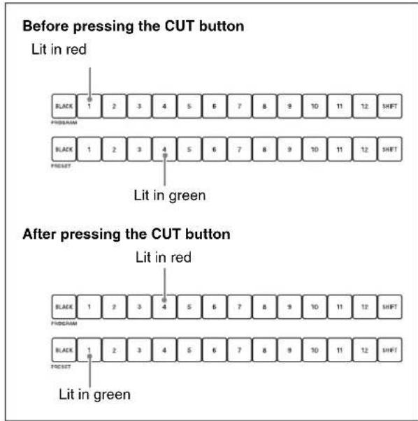
Each time the CUT button is pressed. the program output video switches between the video signals selected with the PROGRAM selection button and PRESET selection button.
When using the BKDF-902

flowchart
graph TD
    A["Key 1"] --> B["Key 2"]
    A --> C["Key 3"]
    D["Key 4"] --> E["Key 3"]
    D --> F["Key 4"]
    G["Keyboard 1"] --> H["Keyboard 2"]
    I["Keyboard 3"] --> J["Keyboard 4"]
    K["Keyboard 1"] --> L["Keyboard 2"]
    M["Keyboard 3"] --> N["Keyboard 4"]
    O["Keyboard 1"] --> P["Keyboard 2"]
    Q["Keyboard 3"] --> R["Keyboard 4"]
1 In the M/E transition block, press the BKGD next transition selection button, lighting it.
2 Press an M/E bus A selection button in the M/E cross-point bus block or a PROGRAM bus selection button in the PROGRAM/PRESET cross-point bus block to select the video that appears before the cut.
The pressed button lights in red, and the selected video becomes the program output video.
3 Press an M/E bus B selection button in the M/E cross-point bus block or a PRESET bus selection button in the PROGRAM/PRESET cross-point bus block to select the video that appears after the cut.
The pressed button lights in green, and the selected video appears in the preview screen.
4 Press the CUT button.
The program output and preview output video are switched instantly. The colors of the buttons in the cross-point block change to reflect the switch.
Example: When PROGRAM bus selection button 1 and PRESET bus selection button 4 are selected
Before pressing the CUT button

After pressing the CUT button

Each time the CUT button is pressed, the program output video switches between the video signals selected with the PROGRAM bus selection button and PRESET bus selection button.
Cutting by using GPI output
You can control playback timing by sending GPI signals to playback devices connected to the switcher.
For example, if you want the background to switch when display of a clip used by a key reaches full-screen display, you can proceed as follows.
For information about GPI output settings, see page 166.
1 First, in the Delay menu of the Transition sub menu, set the following parameters.
(Specify when the background switch occurs, as a number of frames after the start of clip playback.)
| Knob Parameter Description Settings | |||
| F1 C-Delay Rate Cut delay time 0 to 999 | (frames) | ||
| F2 AT-Delay Rate Auto transition delay time | 0 to 999 (frames) | ||
2 Cue up the playback device.
3 While holding down the WIPE transition type selection button, press the DME button.
CG Wipe is selected
4 Turn on the key that uses the signal input from the playback device.
5 Press the CUT button.
Using Transitions to Switch to the Next Video (Mix and Wipe)
Instead of cutting instantly to the next video, you can reveal it gradually by applying a variety of video effects. This switcher provides the following two main types of transition effects.
- Effects that cause the next video to gradually appear over the original video (mix)
- Effects in which the next video wipes away the original video (wipe)
Basic transition effect operations
The figure below shows the flow of transitions that use transition effects.

flowchart
graph TD
    A["Select the program output video."] --> B["Select an effect (mix or wipe)."]
    B --> C["Select the video that you want to appear next."]
    C --> D["Execute the transition."]
How to execute transitions
You can execute a transition by doing one of the following.
- Press the AUTO TRANS button to execute the transition automatically.
- Use the fader lever to execute the transition manually.
Buttons and controls used to execute transitions


flowchart
graph TD
    A["NORM/REV button"] --> B["REVERSE button"]
    B --> C["TRANSIT"]
    C --> D["MIX"]
    C --> E["KEY1"]
    C --> F["KEY2"]
    C --> G["KEY3"]
    C --> H["KEY4"]
    C --> I["NEXT TRANSITION"]
    I --> J["FADER LIMIT"]
    I --> K["NORM REV"]
    I --> L["DIRECTION"]
    L --> M["CHUT"]
    L --> N["AUTO TRANS"]
    O["KEY LAYER"] --> P["TRIY1"]
    Q["MIX"] --> R["TRANSITION TYPE"]
    S["RPE"] --> T["FADER LIMIT"]
    U["NORM REV"] --> V["NORM"]
    W["DIRECTION"] --> X["CHUT"]
    Y["Cut"] --> Z["AUTO TRANS"]
    AA["Transition indicators"] --> AB["Fader lever"]
    AC["AUTO TRANS button"] --> AD["BKDF-902"]
Using the AUTO TRANS buttons
After selecting the video that you want to use, press the AUTO TRANS button. The transition is executed over a time set in advance (the transition rate).
For information about how to set transition rates, see "Setting Transition Rates" (page 117).
Using the fader lever
To execute a transition, move the fader lever in the direction of the lit transition indicator (O). The transition starts, and proceeds according to the rate at which you move the lever.
When you have moved the fader lever all the way to the end of its range, the transition finishes and the transition indicator on the opposite side lights.
Reversing the directions of transitions
If the transition effect is a wipe, you can do the following to reverse the directions of transitions.
Using the REVERSE button (when using the BKDF-901) or the REV button (when using the BKDF-902)
Press the REVERSE button (when using the BKDF-901) or the REV button (when using the BKDF-902), lighting it, to cause transitions to proceed in the reverse direction. Press the button again, turning it off, to cause transitions to proceed in the normal (forward) direction.
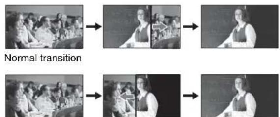
When you press the REVERSE button (when using the BKDF-901) or the REV button (when using the BKDF-902)
Using the NORM/REV button
Press the NORM/REV button, lighting it, to select alternating normal and reverse direction transitions. Each time a transition finishes, the direction reverses and the REVERSE (when using the BKDF-901) or the REV button (when using the BKDF-902) button lights or goes out. Press the lit NORM/ REV button, turning it off, to return to transitions that always proceed in the same direction.
When you press the NORM/REV button

flowchart
graph LR
    A["First transition"] --> B["Speaker"]
    B --> C["Second transition"]
Limiting the effective range of the fader lever
You can limit the effective range of the fader lever (cause transitions to end before the fader lever reaches the top or bottom).


flowchart
graph TD
    A["KEY SRC button"] --> B["BASE"]
    B --> C["POWER"]
    C --> D["SUB SFP"]
    D --> E["WARP"]
    E --> F["LIGHT"]
    F --> G["USER"]
    H["SHIFT"] --> I["MATTS"]
    I --> J["INPUT"]
    J --> K["MV"]
    K --> L["SYSTEM"]
    L --> M["STATUS"]
    M --> N["STILL"]
    O["KEY SRC button"] --> P["BASE"]
    P --> Q["POWER"]
    Q --> R["SUB SFP"]
    R --> S["WARP"]
    S --> T["LIGHT"]
    T --> U["USER"]
    V["KEY SRC button"] --> W["BASE"]
    W --> X["POWER"]
    X --> Y["SUB SFP"]
    Y --> Z["WARP"]
    Z --> AA["LIGHT"]
    AA --> AB["USER"]
    AC["FADER LIMIT button"] --> AD["KEY LIME"]
    AD --> AE["HORN REV"]
    AE --> AF["DIRECTION"]
    AF --> AG["CUT"]
    AG --> AH["AUTO TRANS"]
    AI["KEY LIME"] --> AJ["KEY LIME"]
    AK["KEY LIME"] --> AL["KEY LIME"]
    AM["KEY LIME"] --> AN["KEY LIME"]
    AO["KEY LIME"] --> AP["KEY LIME"]
    AQ["KEY LIME"] --> AR["KEY LIME"]
    AS["KEY LIME"] --> AT["KEY LIME"]
    AU["KEY LIME"] --> AV["KEY LIME"]
    AW["KEY LIME"] --> AX["KEY LIME"]
    AY["KEY LIME"] --> AZ["KEY LIME"]
    BA["KEY LIME"] --> BB["KEY LIME"]
    BC["KEY LIME"] --> BD["KEY LIME"]
    BE["KEY LIME"] --> BF["KEY LIME"]
    BG["KEY LIME"] --> BH["KEY LIME"]
    BI["KEY LIME"] --> BJ["KEY LIME"]
    BK["KEY LIME"] --> BL["KEY LIME"]
    BM["KEY LIME"] --> BN["KEY LIME"]
    BO["KEY LIME"] --> BP["KEY LIME"]
    BQ["KEY LIME"] --> BR["KEY LIME"]
    BS["KEY LIME"] --> BT["KEY LIME"]
    BU["KEY LIME"] --> BV["KEY LIME"]
    BW["KEY LIME"] --> BX["KEY LIME"]
    BY["KEY LIME"] --> BZ["KEY LIME"]
    CA["KEY LIME"] --> CB["KEY LIME"]
    CC["KEY LIME"] --> CD["KEY LIME"]
    CE["KEY LIME"] --> CF["KEY LIME"]
    CG["KEY LIME"] --> CH["KEY LIME"]
    CI["KEY LIME"] --> CJ["KEY LIME"]
    CK["KEY LIME"] --> CL["KEY LIME"]
    CM["KEY LIME"] --> CN["KEY LIME"]
    CO["KEY LIME"] --> CP["KEY LIME"]
    CEI["KEY LIME"] --> CBU
    CEJ["KEY LIME"] --> CBU
    CEK["KEY LIME"] --> CBU
    CEL["KEY LIME"] --> CBU
    CEM["KEY LIME"] --> CBU
    CEN["KEY LIME"] --> CBU
    CEO["KEY LIME"] --> CBU
    CEP["KEY LIME"] --> CBU
    CEQ["KEY LIME"] --> CBU
    CER["KEY LIME"] --> CBU
    CES["KEY LIME"] --> CBU
    CEU1["KEY LIME"] --> CBU
    CEU2["KEY LIME"] --> CBU
    CEU3["KEY LIME"] --> CBU
    CEU4["KEY LIME"] --> CBU
    CEU5["KEY LIME"] --> CBU
    CEU6["KEY LIME"] --> CBU
    CEU7["KEY LIME"] --> CBU
    CEU8["KEY LIME"] --> CBU
    CEU9["KEY LIME"] --> CBU
    CEU10["KEY LIME"] --> CBU
    CEU11["KEY LIME"] --> CBU
    CEU12["KEY LIME"] --> CBU
    CEU13["KEY LIME"] --> CBU
    CEU14["KEY LIME"] --> CBU
    CEU15["KEY LIME"] --> CBU
    CEU16["KEY LIME"] --> CBU
    CEU17["KEY LIME"] --> CBU
    CEU18["KEY LIME"] --> CBU
    CEU19["KEY LIME"] --> CBU
    CEU20["KEY LIME"] --> CBU
    CEU21["KEY LIME"] --> CBU
    CEU22["KEY LIME"] --> CBU
    CEU23["KEY LIME"] --> CBU
    CEU24["KEY LIME"] --> CBU
    CEU25["KEY LIME"] --> CBU
    CEU26["KEY LIME"] --> CBU
    CEU27["KEY LIME"] --> CBU
    CEU28["KEY LIME"] --> CBU
    CEU29["KEY LIME"] --> CBU
    CEU30["KEY LIME"] --> CBU
    CEU31["KEY LIME"] --> CBU
    CEU32["KEY LIME"] --> CBU
    CEU33["KEY LIME"] --> CBU
    CEU34["KEY LIME"] --> CBU
    CEU35["KEY LIME"] --> CBU
    CEU36["KEY LIME"] --> CBU
    CEU37["KEY LIME"] --> CBU
    CEU38["KEY LIME"] --> CBU
    CEU39["KEY LIME"] --> CBU
    CEU40["KEY LIME"] --> CBU
    CEU41["KEY LIME"] --> CBU
    CEU42["KEY LIME"] --> CBU
    CEU43["KEY LIME"] --> CBU
    CEU44["KEY LIME"] --> CBU
    CEU45["KEY LIME"] --> CBU
    CEU46["KEY LIME"] --> CBU
    CEU47["KEY LIME"] --> CBU
    CEU48["KEY LIME"] --> CBU
    CEU49["KEY LIME"] --> CBU
    CEU50["KEY LIME"] --> CBU
    CEU51["KEY LIME"] --> CBU
    CEU52["KEY LIME"] --> CBU
    CEU53["KEY LIME"] --> CBU
    CEU54["KEY LIME"] --> CBU
    CEU55["KEY LIME"] --> CBU
    CEU56["KEY LIME"] --> CBU
    CEU57["KEY LIME"] --> CBU
    CEU58["KEY LIME"] --> CBU
    CEU59["KEY LIME"] --> CBU
    CEU60["KEY LIME"] --> CBU
    CEU61["KEY LIME"] --> CBU
    CEU62["KEY LIME"] --> CBU
    CEU63["KEY LIME"] --> CBU
    CEU64["KEY LIME"] --> CBU
    CEU65["KEY LIME"] --> CBU
    CEU66["KEY LIME"] --> CBU
    CEU67["KEY LIME"] --> CBU
    CEU68["KEY LIME"] --> CBU
    CEU69["KEY LIME"] --> CBU
    CEU70["KEY LIME"] --> CBU
    CEU71["KEY LIME"] --> CBU
    CEU72["KEY LIME"] --> CBU
    CEU73["KEY LIME"] --> CBU
    CEU74["KEY LIME"] --> CBU
    CEU75["KEY LIME"] --> CBU
    CEU76["KEY LIME"] --> CBU
    CEU77["KEY LIME"] --> CBU
    CEU78["KEY LIME"] --> CBU
    CEU79["KEY LIME"] --> CBU
    CEU80["KEY LIME"] --> CBU
Limiting the range by using a menu
Press the FADER LIMIT button to enable the fader limit function. If you then press the FADER LIMIT button twice, the Fader Limit menu appears.
When using the BKDF-901: Rotate the F1 knob to set the limit (0.0 to 100%).
When using the BKDF-902: If you press the FADER LIMIT button in the M/E transition block, rotate the F1 knob to set the limit (0.0 to 100%). If you press the FADER LIMIT button in the PROGRAM/PRESET transition block, rotate the F2 knob to set the limit (0.0 to 100%).
Limiting the range to the desired position
When using the BKDF-901: Move the fader lever to the desired position, press the FADER LIMIT button, lighting it, and then press the SHIFT button of the DME/SETUP block, or press and hold the SHIFT button, move the fader lever to the desired position, and release the SHIFT button.
When using the BKDF-902: Press and hold the KEY SRC button, move the fader lever to the desired position, and release the KEY SRC button.
Switching with Mix Transitions
Mixes are transitions in which the next video fades into the original video, finally replacing it. You can choose from among the following three types of mix transitions.

natural_image
Three sequential black-and-white photos showing a group of people in a meeting or classroom setting, with no visible text or symbols.- MIX transition
This is a transition in which the original video gradually fades out while the next video gradually fades in. At the midpoint of the transition (with the fader lever at the center of its range) the output levels of the original and the next video are both 50%.
• FAM (full additive mix) transition
This is a transition in which the next video gradually fades in to cover the original video, which is unchanged at the start of the transition. At the midpoint of the transition, the output levels of the original and the next video are both 100%. Then the original video begins to gradually fade out.
• NAM (non-additive mix) transition
The output levels of the original and next video vary in the same way as FAM, but instead of adding the two video signals for output to program output, the two signals are compared and only the signal with the highest luminance level is output.
Basic mix operations
Use the following procedure to switch between video signals by using a mix.
When using the BKDF-901

1 In the transition block, press the BKGD next transition selection button, lighting it.
2 In the cross-point bus block, press a PROGRAM selection button to select the video that appears before the transition.
3 In the cross-point bus block, press a PRESET selection button to select the video that appears after the transition.
4 Select the type of transition by pressing a transition type selection button.
MIX: Press the MIX button, lighting it.
FAM: Press the MIX button and the WIPE (FAM) button at the same time, lighting both buttons.
NAM: Press the MIX button and the DME (NAM) button at the same time, lighting both buttons.
5 Set the transition rate as required.
For information about how to set transition rates, see "Setting Transition Rates" (page 117).
6 Execute the transition by pressing an AUTO TRANS button or by moving the fader lever.
The next video is gradually mixed into the original video, and gradually replaces it.

natural_image
Three sequential black-and-white photos showing a group of people in a meeting or classroom setting, with no visible text or symbols.Each time you press the AUTO TRANS button or move the fader lever, a mix transition is executed between the two currently selected video signals.
When using the BKDF-902
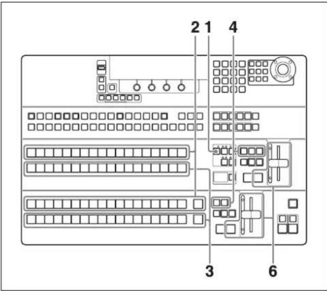
1 In the M/E transition block, press the BKGD next transition selection button, lighting it.
2 Press an M/E bus A selection button in the M/E cross-point bus block or a PROGRAM bus selection button in the PROGRAM/PRESET cross-point bus block to select the video that appears before the cut.
3 Press an M/E bus B selection button in the M/E cross-point bus block or a PRESET bus selection button in the PROGRAM/PRESET cross-point bus block to select the video that appears after the cut.
The pressed button lights in green, and the selected video appears in the preview screen.
4 Select the type of transition by pressing a transition type selection button.
MIX: Press the MIX button, lighting it.
FAM: Press the MIX button and the WIPE (FAM) button at the same time, lighting both buttons.
NAM: Press the MIX button and the DME (NAM) button at the same time, lighting both buttons.
5 Set the transition rate as required.
For information about how to set transition rates, see "Setting Transition Rates" (page 117).
6 Execute the transition by pressing an AUTO TRANS button or by moving the fader lever.
The next video is gradually mixed into the original video, and gradually replaces it.

natural_image
Three sequential black-and-white photos showing a group of people in a meeting or conference setting, with no visible text or symbols.Each time you press the AUTO TRANS button or move the fader lever, a mix transition is executed between the two currently selected video signals.
Switching with Wipe and DME Wipe Transitions
Wipes are transitions in which the next video gradually wipes away the original video. There are 98 different wipe patterns which specify how the original video is wiped away, in addition to 231 patterns created with DME effects (DME wipe patterns).

natural_image
Three sequential grayscale images showing a group of people in a meeting or classroom setting, with no visible text or symbols.For details, see "Wipe" (page 189) and "DME Wipe" (page 192).
Basic wipe and DME wipe operations
Use the following procedure to switch between video signals by using a wipe.
When using the BKDF-901

1 In the transition block, press the BKGD next transition selection button, lighting it.
2 In the cross-point bus block, press a PROGRAM selection button to select the video that appears before the transition.
3 In the cross-point bus block, press a PRESET selection button to select the video that appears after the transition.
4 Press the WIPE or DME transition type selection button, lighting it.
The WIPE menu or the DME menu appears in the display panel.
WIPE menu
Wipe Pattern Pat=0 Wid=9.1 Soft=12.5 Src=W.Bd
DME menu
M/E DME Pattern Pat=0
Note
DME must be enabled to use DME wipe patterns. Pressing the DME button when DME is not enabled has no effect. To enable and disable DME, press the DME ENABLE button (see page 14) in the KEYER block.
5 Rotate the F1 knob to select a wipe pattern or DME wipe pattern.
To select by entering a pattern number, press the F1 knob, enter the number in the numeric keypad, and then press the ENTER button.
For pattern numbers, see "Pattern List" (page 189).
6 Set the transition rate as required.
For information about how to set transition rates, see "Setting Transition Rates" (page 117).
7 Execute the transition by pressing an AUTO TRANS button or by moving the fader lever.
According to the selected pattern, the next video gradually wipes the original video away.

When using the BKDF-902

1 In the M/E transition block, press the BKGD next transition selection button, lighting it.
2 Press an M/E bus A selection button in the M/E cross-point bus block or a PROGRAM bus selection button in the PROGRAM/PRESET cross-point bus block to select the video that appears before the cut.
3 Press an M/E bus B selection button in the M/E cross-point bus block or a PRESET busselection button in the PROGRAM/PRESET cross-point bus block to select the video that appears after the cut.
The pressed button lights in green, and the selected video appears in the preview screen.
4 In the M/E transition block, press the WIPE or DME transition type selection button, lighting it. Or in the PROGRAM/PRESET transition block, press the WIPE transition type selection button, lighting it.
When the WIPE button of the M/E transition block is pressed, the M/E WIPE menu appears in the display panel.
M/E WIPE menu
M/E Wipe Pattern
Pat=0 Wid=9.1 Soft=12.5 Src=W.Bd
When the DME button is pressed, the DME menu appears in the display panel.
DME menu
M/E DME Pattern
Pat=0
When the WIPE button of the PROGRAM/PRESET transition block is pressed, the P/P WIPE menu appears in the display panel.
P/P WIPE menu
P/P Wipe Pattern
Pat=0 Wid=9.1 Soft=12.5 Src=W.Bd
Note
DME must be enabled to use DME wipe patterns. Pressing the DME button when DME is not enabled has no effect. To enable and disable DME, press the DME ENABLE button (see page 14) in the KEYER block.
5 Rotate the F1 knob to select a wipe pattern or DME pattern.
To select by entering a pattern number, press the F1 knob, enter the number in the numeric keypad, and then press the ENTER button.
For pattern numbers, see "Pattern List" (page 189).
6 Set the transition rate as required.
For information about how to set transition rates, see "Setting Transition Rates" (page 117).
7 Execute the transition by pressing an AUTO TRANS button or by moving the fader lever.
According to the selected pattern, the next video gradually wipes the original video away.

Tips
- Unlike mixes, wipes and DME wipes allow the direction of the transition to be set.
For details, see “Reversing the directions of transitions” (page 112).
- You can adjust wipe and DME wipe patterns.
For details, see "Adjusting Wipes and Keys" (page 132).
Setting Transition Rates
Transition rates specify the time required to complete a transition after an AUTO TRANS button is pressed. You can set the desired transition rate across the range 1 to 999 frames.
1 When using the BKDF-901: In the transition block, press the MIX transition type selection button.
When using the BKDF-902: In the M/E or PROGRAM/PRESET transition block, press the MIX transition type selection button.
The Rate menu appears in the display panel.
Rate menu
| Rate | PGM=30 DSK=30 FTB=30 |
2 Rotate the F2, F3 or F4 knob to change the corresponding transition rate.
When using the BKDF-901
| Knob | Parameter Description Settings | |
| F2 PGM | Transition rate for background transitions and key transitions | 1 to 999 |
| F3 DSK | Transition rate for downstream key transitions (see page 130) | 1 to 999 |
| F4 FTB | Transition rate for fade to black transitions (see page 131) | 1 to 999 |
When using the BKDF-902
| Knob | Parameter Description Settings | |
| F1 ME | Transition rate for background transitions and key transitions | 1 to 999 |
| F2 PGM | Transition rate for background transitions | 1 to 999 |
| F3 DSK | Transition rate for downstream key transitions (see page 130) | 1 to 999 |
| F4 FTB | Transition rate for fade to black transitions (see page 131) | 1 to 999 |
Using Color Mattes
Video input signals are not the only signals that you can use in transitions.
You can also use the switcher's internally generated color matte signals. Up to four of these signals (Matte1 to Matte4) can be assigned to the cross-point selection buttons, allowing you to use them as backgrounds, in keys, and as modifiers. You can change the colors of these color matte signals.
Assigning Color Mattes to Cross-Point Selection Buttons
Use the menu system to assign color mattes to the desired buttons.
For details, see "Assigning video input signals to cross-point selection buttons" (page 76).
Changing the Colors of Color Mattes

1 When using the BKDF-901: If the SHIFT button in the DME/SETUP block is not lit, press it to light it.
When using the BKDF-902: Skip to step 2.
2 Press the MATTE button.
The Matte Color menu appears in the display panel.
Matte Color menu
| Matte Color |
| Matte 1 Lum=100.0 Sat=100.0 Hue=263.5 |
3 Rotate the F1 knob to select a matte signal (Matte1 to Matte4), and then rotate the F2, F3, and F4 knobs to adjust the color.
| Knob | Parameter Description Settings | |
| F2 | Lum Luminance 0.0 to 108.6 | |
| F3 | Sat Saturation 0.0 to 100.0 | |
| F4 | Hue Hue 0.0 to 359.5 | |
Using Color Mattes in Background Transitions
Color mattes can be used in background transitions in the same way as video signals input to the switcher.
Select the cross-point selection button to which the desired color matte signal has been assigned, and then execute the transition.
For details about how to execute background transitions, see "Switching Backgrounds" (page 109).
Using Internally Stored Still Images
The switcher is equipped with internal memory for the storage of still image files. You can use images stored in this memory in transitions and compositions.
Tip
The supported still image file formats include 24-bit JPG (jpeg) and BMP (bitmap), TGA (targa), and 32-bit TGA (targa).
Acquiring Still Image Files
You can acquire still image files by downloading them from a USB flash drive, or by capturing program output into image files (up to 100 files).
Downloading still images from USB flash drives

1 Store the images that you want to use on a USB flash drive, and connect the USB flash drive to the USB MEMORY connector.
Note
The supported file formats are 24-bit JPG (jpeg) and BMP (bitmap), TGA (targa), and 32-bit TGA (targa). Before starting, create a folder name "Stl" in the root directory of the USB flash drive. Copy the files that you want to use to that folder, assigning names in the format "stl**" (where ** is a number from 00 to 99).
2 When using the BKDF-901: If the SHIFT button in the DME/SETUP block is not lit, press it to light it.
When using the BKDF-902: Skip to step 3.
3 Press the STILL button.
The Still Store menu appears in the display panel.
4 Use the ◀ and ▷ buttons in the numeric keypad to switch to the Download sub menu.
5 Rotate the F4 knob to specify USB as the download source.
6 Set the parameters.
| Knob | Parameter | Description Settings | |
| F1 Dst | Storage | destinationa) | IN01 to IN24,STL1 to STL4 |
| F2 File | File numberb) | 00 to 99 | |
a) To output still images that have been downloaded to IN01 to IN24, the corresponding frame synchronizers must be enabled. Selection of IN01 to IN24 makes it impossible to select video that is input to the corresponding input connectors. For more information about how to enable frame synchronizers, see “Using the internal frame synchronizers” (page 79).
b) An asterisk (*) appears after still image files that have already been stored.
Note
If you have changed the display names of input signals and internal signals (see page 74), those names appear in the F1 knob operation area.
7 Press the F4 knob and hold it down for one second or longer.
Downloading from the USB flash drive starts. During the download, the STILL button lights in red. When the download finishes, the button returns to lit in orange.
Notes
- Still image files downloaded from USB flash drives are also stored in the non-volatile memory of the control panel.
- If you select USB with the F4 knob, thumbnail images are not displayed in GUI menu screens.
Capturing program output

Tip
To save an input image frozen with the internal frame synchronizers, first output the image to program output and then use the procedure described below to save it to still image memory.
For details about the internal frame synchronizers, see "Using the internal frame synchronizers" (page 79).
1 When using the BKDF-901: With the video that you want to capture being output to program output, press the SHIFT button in the DME/SETUP block, lighting it.
When using the BKDF-902: With the video that you want to capture being output to program output, skip to step 2.
2 Press the STILL button.
The Still Store menu appears in the display panel.
3 Use the ◀ and ▷ buttons in the numeric keypad to switch to the Image Capture sub menu.
4 Set the parameters.
| Knob | Parameter Description Settings | ||
| F1 Frz | Freeze mode | Frm: Frame | Odd: Odd fieldEven: Even field |
| F2 File | File number | 00 to 99 | |
5 Press the F4 knob and hold it down for one second or longer.
Capture of program output begins. During the capture, the STILL button lights in red. When the capture finishes, the button returns to lit in orange.
Note
Captured still images are stored in the non-volatile memory of the control panel. To use still images in video transitions and compositions, they must be downloaded to still image memory.
Downloading captured still images to still image memory
1 After completion of the image capture in step 5 of the previous procedure, use the ◀ and ▷ buttons in the numeric keypad to switch to the Download sub menu.
2 Rotate the F4 knob to specify "CP" (control panel) as the download source.
3 Set the parameters.
| Knob | Parameter | Description Settings | |
| F1 Dst | Storage | destination a) | IN01 to IN24,STL1 to STL4 |
| F2 File | File number b) | 00 to 99 | |
a) To output still images that have been downloaded to IN01 to IN24, the corresponding frame synchronizers must be enabled. Selection of IN01 to IN24 makes it impossible to select video that is input to the corresponding input connectors. For more information about how to enable frame synchronizers see “Using the internal frame synchronizers” (page 79).
b) Select a captured image.
Note
If you have changed the display names of input signals and internal signals (see page 74), those names appear in the F1 knob operation area.
4 Press the F4 knob and hold it down for one second or longer.
Downloading to the internal still image memory starts. During the download, the STILL button lights in red. When the download finishes, the button returns to lit in orange.
Using Stored Still Images in Background Transitions
Images stored in still image memory can be used in background transitions in the same way as video signals input to the switcher.
To use a stored still image, select the cross-point corresponding to the storage location (IN01 to IN24, STL1 to STL4).
For details about how to execute background transitions, see “Switching Backgrounds” (page 109).
Using 32-bit TGA Still Image Files in Keys
Tip
The 32-bit TGA format supports an (alpha) channel for storage of additional data, such as key data. By using this format, you can store key and fill data in a single image file, which allows you to conserve still image storage memory.
1 See “Downloading still images from USB flash drives” and download a 32-bit TGA file to a still image memory location (STL1 to STL4).
2 Select the target key by pressing a button (KEY1 to KEY4, DSK1, DSK2) in the KEY DELEGATION block (when using the BKDF-901) or in the key/AUX bus control block (when using the BKDF-902).
3 Press the EXT button in the KEYER block.
4 For both the key source (KSrc) and key fill (KIns), select the still image memory location (STL1 to STL4) to which you downloaded a file in step 1.
Note
32-bit files cannot be stored in memory locations other than STL1 to STL4.
Writing Still Images to USB Flash Drives

BKDF-901
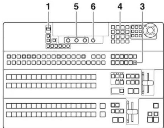
BKDF-902
1 Connect the USB flash drive to which you want to store an image file to the USB MEMORY connector.
2 When using the BKDF-901: If the SHIFT button in the DME/SETUP block is not lit, press it to light it.
When using the BKDF-902: Skip to step 3.
3 Press the STILL button.
The Still Store menu appears in the display panel.
4 Use the ◀ and ▷ buttons in the numeric keypad to switch to the Export Still sub menu.
5 Set the parameters.
| Knob | Parameter | Description Settings | |
| F1 Fmt | File format | BMP, TGA | |
| F2 File | File number | 00 to 99a) |
a) "Overwrite" appears in the F3 knob operation area if a file with the same number already exists on the USB flash drive, and "New File" appears if no file with the same number exists.
6 Press the F4 knob and hold it down for one second or longer.
Export to the USB flash drive starts.
During the download, the STILL button lights in red. When the download finishes, the button returns to lit in orange.
Tip
The exported file is stored in the Stl folder of the USB flash drive. If the Stl folder does not exist, it is created automatically.
Deleting Still Image Files

BKDF-901

BKDF-902

1 When using the BKDF-901: If the SHIFT button in the DME/SETUP block is not lit, press it to light it. When using the BKDF-902: Skip to step 2.
2 Press the STILL button.
The Still Store menu appears in the display panel.
3 Use the ◀ and ▷ buttons in the numeric keypad to switch to the Delete sub menu.
4 Set the parameters.
| Knob | Parameter Description Settings | ||
| F2 File | File number | 00 to 99 | |
| F4 Del | Storage | location of the file to be deleted | CP, USB |
5 Press the F4 knob and hold it down for one second or longer.
Deletion of the still image file begins. During the deletion, the STILL button lights in red. When the deletion finishes, the button returns to lit in orange.
Using Keys to Compose Video
This switcher allows you to add four keys (KEY1 to KEY4) and two downstream keys (DSK1 and DSK2) to the background video.
Key types
The following three key types are available on this switcher.
External keys (EXT): Keys that use separate signals for key fill and key source.
Self keys (SELF): Keys that use the same signal for key fill and key source.
Chroma keys (CK): Unlike the two keys described above, keys that are created on the basis of color data instead of luminance data. Chroma keys cannot be used with downstream keys.
Setting Up Keys
Keys and downstream keys must be set up before they can be used.
To set up external keys and self keys

1 In the KEY DELEGATION block (when using the BKDF-901) or in the key/AUX bus control block (when using the BKDF-902), press the button for the key that you want to set up, lighting it.
2 In the KEYER block, select the key type.
3 In the menu that appears depending on the selected key type, set the following parameters.
External (EXT) key parameters (External Key menu)
To move between parameter groups, use the ◀ and ▷ buttons in the numeric keypad.
Parameter group (1/2)
| Knob | Parameter Description Settings | ||
| F1 KIns | Key fill BLK, IN01 to | IN24, MAT1 to MAT4, STL1 to STL4 | |
| F2 KSrc | Key source | ||
| F3 GN | Gain 0.0 to 1 | 6.00 | |
| F4 Clp | Key reference level | 0.0 to 100.0 | |
Note
If you have changed the display names of input signals and internal signals (see page 74), those names appear in the F1 and F2 knob operation area.
Parameter group (2/2)
| Knob | Parameter | Description Settings |
| F1 | Opac Opaqueness | 0.0 to 100.0 |
| F2 | Inv Inverted | On, Off |
Self (SELF) key parameters (Self Key menu)
To move between parameter groups, use the ◀ and ▷ buttons in the numeric keypad.
Parameter group (1/2)
| Knob | Parameter Description Settings | ||
| F1 KIns | Key fill BLK, IN01 to | IN24, MAT1 to MAT4, STL1 to STL4 | |
| F3 GN | Gain 0.0 to 1 | 6.00 | |
| F4 Clp | Key reference level | 0.0 to 100.0 | |
Note
If you have changed the display names of input signals and internal signals (see page 74), those names appear in the F1 knob operation area.
Parameter group (2/2)
| Knob | Parameter | Description | Settings |
| F1 Opac Opaqueness 0 to 100.0 | |||
| F2 Inv | Inverted | On, Off | |
When using the BKDF-902, you can select key fill and key source signals for external keys by pressing the KEY SRC button.
Setting up chroma keys
A chroma key is a key that cuts out a certain part of a video signal on the basis of a specified reference color. For example, chroma keys are used to create video of foreground subjects against an arbitrary background by shooting the subjects against a blue background, extracting only the subjects for use as a key fill signal, and inserting the key fill signal into the background.
Chroma keys can be used only with KEY1 to KEY4. They cannot be used with DSK1 and DSK2.
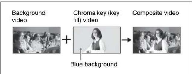
flowchart
graph LR
    A["Background video"] --> C["Chroma key (key fill) video"]
    C --> D["Composite video"]
    C --> E["Blue background"]
The normal procedure for creating a chroma key is to specify the color to be cut out of the video, to use an automatic switcher function to create a key fill video (auto chroma key) from the cut out video, and then to adjust that video manually.
To create an auto chroma key
Use the following procedure to create an auto chroma key.

1 In the KEY DELEGATION block (when using the BKDF-901) or in the key/AUX bus control block (when using the BKDF-902), press the button for the key that you want to set up, lighting it.
2 In the KEYER block, press the EXT button or the SELF button.
When the External Key menu or Self Key menu appears, rotate the F1 knob to select the signal to use in the chroma key.
3 In the KEYER block, press the CK button.
The key type is changed to chroma key.
4 In the joystick block, press the AUTO CK button.
The switcher enters auto chroma key mode, and the CK Auto menu appears in the display panel. At the same time, a cross cursor appears in the preview or program output video.
Tip
You can reselect the signal to use in the chroma key by rotating the F1 knob.
5 Using the joystick, move the cross cursor to the color that you want to cut out (keying color).

Tip
Instead of using the joystick, you can also use the F2 and F3 knobs to adjust.
6 Press the AUTO CK button.
An auto chroma key is created.
To adjust an auto chroma key
After creating an auto chroma key as explained above, use the following procedure to adjust it.

1 In the KEY DELEGATION block (when using the BKDF-901) or in the key/AUX bus control block (when using the BKDF-902), press the button that you used to create the auto chroma key, lighting it.
2 In the KEYER block, press the CK button.
A CK Manual sub menu appears in the display panel.
3 Adjust the parameters.
Chroma key (CK) parameters (Chroma Key menu) When viewed on a vectorscope, the part of the foreground that becomes the key signal (the part that is replaced by the background) appears as a fan shaped area centered around the keying color (see the following figure). You can adjust the shape of this area by adjusting the Angle parameter. You can also adjust the Y, C, and key signals individually.

When there are patches of the background color in the foreground picture, you can remove those patches from the foreground picture (color cancel function). You can suppress the Y component of the video, and also use two parameters (C1 and C2) to adjust the chroma components (see figures below).
Adjust with C1

Adjust with C2
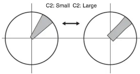
Parameter group (1/4)
| Knob Parameter Description Settings | |||
| F2 Hue | Keying color | hue 0.0 to 359.5 | |
| F3 | GN | Gain 0.0 to 63.99 | |
| F4 Clp | Key reference level 0.0 to 100.0 | ||
Parameter group (2/4)
| Knob Parameter Description Settings | |||
| F1 Y O | Offset value vs. | Angle^a) b) | -45.00 to 45.00 |
| F2 C | Offset value vs. | Angle^a) c) | -45.00 to 45.00 |
| F3 K O | Offset value vs. | Angle^d) | -45.00 to 45.00 |
| F4 Ang | Angle of the a | rea that becomes the key signal (Angle) | 5.00 to 90.00 |
a) Enabled only when Color cancel is set to On.
b) Affects only Y signal of foreground video.
c) Affects only C signals of foreground video.
d) Affects only key signals.
Parameter group (3/4)
| Knob Parameter Description Settings | |||
| F1 | Col | Color cancel | On/Off |
| F2 | Y Suppression of Y component | 0.00 to 31.99 | |
| F3 C1 | Suppression by C1 parametera) | 0.00 to 31.99 | |
| F4 C2 | Suppression by C2 parameter | 0.0 to 100.0 | |
a) The C1 setting is ignored when C2 is anything other than 0.00.
Parameter group (4/4)
| Knob Parameter Description Settings | |||
| F1 | ShL | Positional adjustment of left side of key signal | 0 to 3 |
| F2 | ShR | Positional adjustment of right side of key signal | 0 to 3 |
To adjust key opacity
Use the Other sub menu to adjust the opacity of chroma keys.
The Other sub menu has the following parameter.
| Knob Parameter Description Settings | ||
| F1 Opac | Opacity | 0.0 to 100.0 |
To set the chroma key cursor
Use the following procedure to specify whether the chroma key cursor should be displayed in the program screen or the preview screen.

1 When using the BKDF-901: If the SHIFT button of the DME/SETUP block is not lit, press it to light it.
When using the BKDF-902: Skip to step 2.
2 Press the SYSTEM button.
A settings sub menu of the System sub menu appears in the display panel.
3 Press the ◀ or ▷ button in the numeric keypad until the Other sub menu appears.
“Other” appears in the sub menu title display area. If it is already displayed there, you can skip this step.
4 Rotate the F1 knob to select PGM or PVW.
When using the BKDF-901
| Knob | Parameter | Description Settings | |
| F1 | Cursor | The screenwhere the chroma keycursor appears | PGM:Program screenPVW:Preview screen |
When using the BKDF-902
| Knob | Parameter | Description Settings | |
| F1 | Cursor | The screenwhere the chroma key cursor appears. | M/E PGM:Program screenM/E PVW:Preview screen |
Inserting Keys by a Cut Transition

1 Set up the key signal.
For information about how to set up keys, see “Setting Up Keys” (page 122).

2 Press the next transition selection button that selects the key you have set up (KEY1 to KEY4, multiple selections possible), lighting the button.
3 Press the CUT button.
The key video is inserted instantly into the background video.
When the key is inserted, the key on indicator (red) above the button lights.
When you press the CUT button once more, the indicator goes out and the video returns to the original background video.
Inserting Keys by a Mix Transition
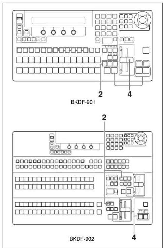
1 Carry out steps 1 and 2 of the previous section, "Inserting Keys by a Cut Transition".
2 Press the MIX button, lighting it.
3 Set the transition rate as required.
For information about how to set transition rates, see "Setting Transition Rates" (page 117).
4 Use an AUTO TRANS button or the fader lever to execute the mix transition.
For information about how to execute a transition, see "Using Transitions to Switch to the Next Video (Mix and Wipe)" (page 111).
Inserting Keys by a Wipe or DME Wipe Transition
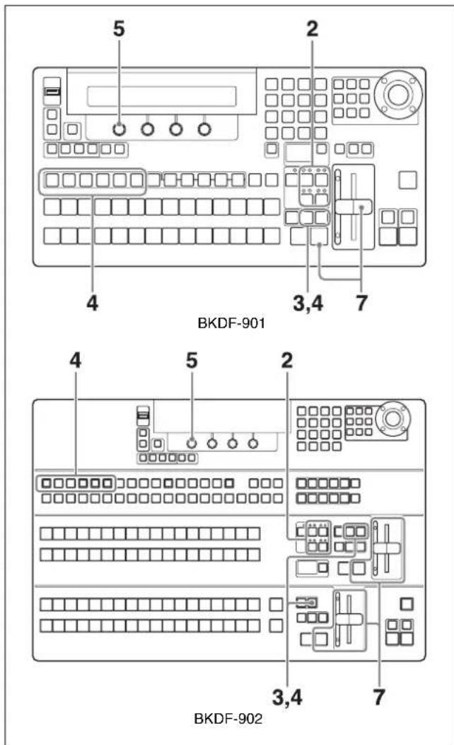
1 Set up the key signal.
For information about how to set up keys, see “Setting Up Keys” (page 122).
2 Press the next transition selection button that selects the key you have set up (KEY1 to KEY4, multiple selections possible), lighting the button.
3 When using the BKDF-901: In the transition block, press the WIPE button or the DME button, lighting the button.
When using the BKDF-902: In the M/E transition block, press the WIPE button or the DME button, lighting it. Or in the PROGRAM/PRESET transition block, press the WIPE button, lighting it.
If you pressed the WIPE button in the transition block, the WIPE menu appears.
If you pressed the WIPE button of the M/E transition block, the M/E WIPE menu appears.
If you pressed the WIPE button of the PROGRAM/PRESET transition block, the P/P WIPE menu appears.
Notes
- DME must be enabled to use DME wipe patterns. Pressing the DME button when DME is not enabled has no effect. To enable and disable DME, press the DME ENABLE button in the KEYER block. When DME is enabled, the DME indicator above the button for the selected key lights in green.
- You can use multiple keys simultaneously in a transition, but when you specify a normal wipe pattern, all of the keys use the same pattern. However, when you specify DME wipe patterns, you can repeat steps 4 and 5 to use different patterns for each key.
4 If you pressed the DME button in step 3, adjust DME wipe patterns for each key.
Select the desired key and then press the DME button again.
The DME menu for the operation target key selected in the KEY appears.
5 Rotate the F1 knob to select a wipe pattern or a DME wipe pattern.
To select by entering a pattern number, press the F1 knob, enter the number in the numeric keypad, and then press the ENTER button.
For pattern numbers, see "Wipe" (page 189) and "DME Wipe" (page 192).
6 Set the transition rate and transition direction as required.
For information about how to set transition rates and transition directions, see “Setting Transition Rates” (page 117) and “Reversing the directions of transitions” (page 112).
Tip
You can adjust wipe and DME wipe patterns.
For details, see "Adjusting Wipes and Keys" (page 132).
7 Execute the transition with an AUTO TRANS button or the fader lever.
Changing Key Priorities
You can specify the priorities of keys 1 to 4. The priorities determine the rank of keys with respect to the background.

1 Press the PRIORITY button, lighting it.
The next transition selection buttons KEY1 to KEY4 light in orange, and the key priority matrix displays the current key priorities.
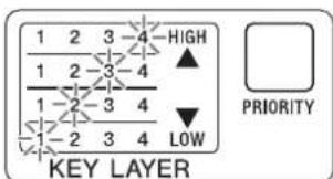
Example: The indicators in the key priority matrix light as shown above when the key priorities are Key 4 > Key 3 > Key 2 > Key 1.
2 Press each of the next transition selection buttons KEY1 to KEY4, beginning with the key that you want to have the highest priority.
The key priority matrix changes to reflect the order in which you pressed the buttons.

Example: The indicators in the key priority matrix light as shown above when you press the next transition selection buttons in the order KEY 3>KEY 1>KEY 4>KEY 2.
If you do not press all four buttons, the priority setting operation is cancelled the next time that you press the PRIORITY button.
3 Move the fader lever all the way to the top or bottom.
The new key priority settings are saved.
Applying DME Effects to Keys

BKDF-901
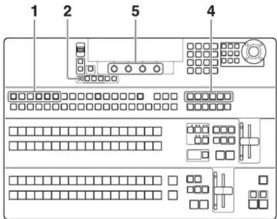
BKDF-902
1 In the KEY DELEGATION block (when using the BKDF-901) or in the key/AUX bus control block (when using the BKDF-902), select the target key of the operation.
2 Press the DME ENABLE button in the KEYER block, lighting it.
For more information about the function of this button, see page 14.
3 When using the BKDF-901: Press the SHIFT button in the DME/SETUP block, lighting it.
When using the BKDF-902: Skip to step 4.
4 Press a DME setting button such as BASIC or BORDER.
5 Rotate the F1 to F4 knobs to adjust the parameters.
For details, see "Customizing DME Effects" (page 134).
Inserting Downstream Keys (with a Cut)

natural_image
Line drawing of a computer control panel with buttons, keys, and a keypad (no text or symbols)BKDF-901

natural_image
Pure electrical circuit lines without any symbols2
BKDF-902
1 Set up the key signal.
For information about how to set up keys, see "Setting Up Keys" (page 122).
2 In the transition block (when using the BKDF-901) or in the DSK/fade to black control block (when using the BKDF-902), press the DSK1 ON or DSK2 ON button.
The pressed button lights, and a downstream key is inserted.
Press the button again to delete the downstream key and turn the button off.
Inserting Downstream Keys (with a Mix)
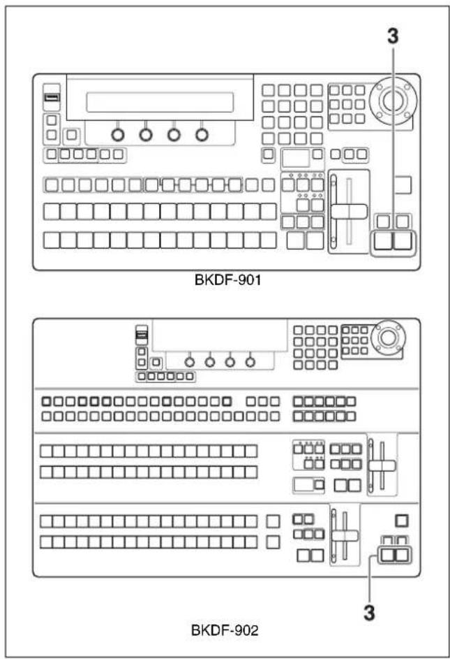
1 Set up the key signal.
For information about how to set up keys, see "Setting Up Keys" (page 122).
2 Set the transition rate for downstream keys.
For information about how to set transition rates, see "Setting Transition Rates" (page 117).
3 Press the DSK1 or DSK2 AUTO TRANS button.
The transition is executed at the specified transition rate.
Note
Some functions cannot be used with downstream keys. Functions that are not available include chroma key, wipe patterns, DME wipe patterns, key masks (but box mask is available), and edges.
Using Fade to Black
You can use the switcher's internally generated black signals in transitions. A transition in which the background is replaced by a black signal is called "fade to black".
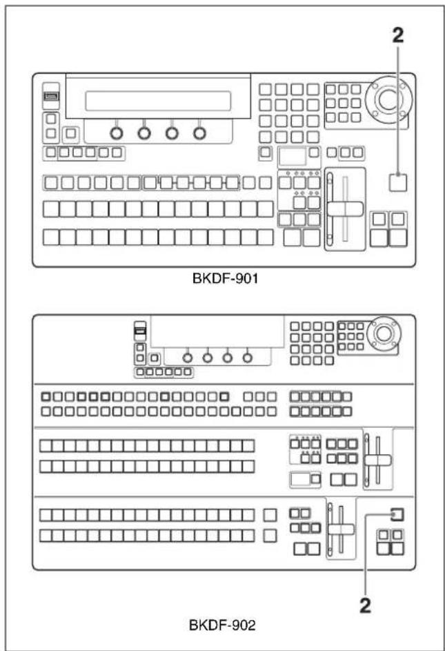
1 Set the transition rate for fade to black.
For information about how to set transition rates, see "Setting Transition Rates" (page 117).
2 Press the FTB button in the transition block (when using the BKDF-901) or in the DSK/fade to black control block (when using the BKDF-902).
The video being output to program output fades out according to the specified transition rate, and is replaced by a black screen.
If you press the FTB button once more after the fade to black finishes, the switcher executes a transition back to the original video.
If you press the FTB button during a fade to black, the original video is restored instantly.
Tip
Fade to black has the highest priority among all transitions. You can press the FTB button during execution of any other type of transition to fade to a black screen.
Adjusting Wipes and Keys
Chapter
5
You can add detailed effects to the wipe patterns used in transitions and to the keys which are inserted into background video.
When the sub menu and parameter names that appear in the display panel are different from the sub menu and parameter names that appear in GUI menu screens, this chapter shows both, with the names that appear in GUI menu screens enclosed in parentheses.
For more information about the names that appear in GUI menu screens, see “Menu Operations in the GUI Menus” (page 64).
Customizing Wipe Patterns
When you operate with transitions and keys, you can customize the selected wipe pattern.
For example, you can add borders to a pattern, or modify the pattern's shape or position. Customized patterns can be registered as user patterns.

Border example
For information about how to select wipe patterns, see “Switching with Wipe and DME Wipe Transitions” (page 115) or “Inserting Keys by a Wipe or DME Wipe Transition” (page 127).
Adding Borders to Wipe Patterns
You can add borders by adjusting the parameters of the Wipe Pattern (Pattern) sub menu and the Wipe Border Color (Border Color) sub menu.
To display the Wipe Pattern (Pattern) and Wipe Border Color (Border Color) sub menus
When using the BKDF-901: Press the WIPE button in the transition block.
When using the BKDF-902: Press the WIPE button in the M/E transition block or in the PROGRAM/PRESET transition block.
The most recently used sub menu appears in the display panel.
To switch between sub menus, use the ◀ and ▷ buttons in the numeric keypad.
Wipe Pattern (Pattern) sub menu parameters
Adjust the following parameters to create a border.
| Operation | Knob | Parameter Settings | |
| Set the border width | F2 Wid | (Border Width) | 0.0 to 100.0 (Set to 0.0 if you do not want to add a border.) |
| Set the border softness | F3 Soft | (Border Softness) | 0.0 to 100.0 |
| Select video to use in the border | F4^a) | Src (Border Source) | BLK: Black signal IN01 to In24: Input signals 1 to 24 MAT1 to MAT4: Color matte signals 1 to 4 STL1 to STL4: Still images 1 to 4 W.Bd (Wipe Border Matte): Wipe border matte |
a) If you have used the F4 knob to change the display names of input signals and internal signals (see page 74), the new display names appear.
Wipe Border Color (Border Color) sub menu parameters
Adjust the following parameters to adjust the border color.
| Operation Knob Parameter Settings | |||
| Adjust the border luminance | F2 Lum | (Luminance) 0.0 to | 108.6 |
| Adjust the saturation (color density) of the border color | F3 Sat | (Saturation) 0.0 to | 100.0 |
| Adjust the hue of the border color | F4 Hue | 0.0 to 359.5 | |
Modifying Wipe Patterns
You can modify wipe patterns by adjusting the parameters of the Wipe Modify (Modify) sub menu.
To display the Wipe Modify (Modify) sub menu
Press the WIPE POS button in the joystick block. If another sub menu is displayed, you can switch to the Wipe Modify sub menu by pressing the ◀ and ▷ buttons in the numeric keypad.
Wipe Modify (Modify) sub menu parameters
Adjust the following parameters to change the pattern shape and position.
| Operation | Knob Joystick | Parameter | Settings |
| Set the pattern aspect ratio | F1 | Asp (Aspect) | -1.000 to 1.000 |
| Set the pattern horizontal position (X coordinate) | F2Move left and right | PX (Center Position X) | -1.000 to 1.000 |
| Set the pattern vertical position (Y coordinate) | F3Move up and down | PY (Center Position Y) | -1.000 to 1.000 |
| Set the pattern rotation angle | F4Rotate clockwise/ counterclockwise | Ang (Angle) | -16.000 to 16.000 |
Registering User Patterns
You can use the User sub menu to register customized wipe patterns.
1 Customize a wipe pattern with one of the sub menus.
2 Press the ◀ or ▷ button in the numeric keypad until the User sub menu appears.
3 Rotate the F1 knob in the Display Panel/Menu Control Block to select the number under which to register the pattern.
| Knob | Parameter | Description | Settings |
| F1 | Usr (User Pattern) | Number under which to register the pattern | 120 to 159a) |
a) An asterisk (*) appears after the number when a user pattern has already been registered.
4 Press the F2 knob and hold it down for one second or longer.
The pattern is registered under the number selected in step 3.
To unregister a pattern
Rotate the F1 knob in the Display Panel/Menu Control Block to select the pattern number to unregister, and then press the F4 knob and hold it down for one second or longer.
Customizing DME Effects
You can use the DME menu to customize the DME effects (digital multi effects) used in transition and key operations. DME effects allow you to change the position, size, and shape of images in three-dimensional space.
This switcher provides six DME channels. Each channel can be used independently, and channels can also be combined to create more complex and sophisticated effects. The number of DME channels currently in use appears at the upper right of the display panel (Now Using DMEs=number of channels).
| Adjustment Sub menu used (menu names as shown in GUI menu screens only) | |
| • Change position, shape, and size.• Set up DME channel. | DME Basic |
| Add borders. Border | |
| Change color type (Chroma Control). | Sub Effects |
| Adjust 3D DME warp effects. Warp | |
| Add lighting effects. | Light |
| Register user patterns. User | |
For information about how to select DME wipe patterns, see “Switching with Wipe and DME Wipe Transitions” (page 115) or “Inserting Keys by a Wipe or DME Wipe Transition” (page 127).
For information about how to apply DME effects to keys, see “Applying DME Effects to Keys” (page 129).
Note
Customizations to DME effects are lost when the settings of the switcher are reset and when the switcher is powered off. If you want to reuse customized DME effects, register them as events.
For details, see "Registering Events" (page 151).
To restore the default values for all settings in a sub menu of the DME menu (reset)
When using the BKDF-901: Display the sub menu that you want to reset, hold down the SHIFT button in the DME/SETUP block, and then press the DEFAULT button in the joystick block.
When using the BKDF-902: Display the sub menu that you want to reset, hold down the KEY SRC button in the key/AUX control block, and then press the DEFAULT button in the joystick block.
Changing the Position, Shape, and Size of Images
Use the sub menus of the DME Basic sub menu to do the following.
| Sub menu Operation | |
| Position a) | Set the position of the image |
| Rotation a) | Set the rotation angle of the image |
| xxx Aspect b)(Aspect) | Set the aspect ratio of the image |
| Crop Crop part of the image | |
| xxx Setup (Setup)b) | Enable or disable DMESelect whether to use global coordinates |
a) Shown only in GUI menu screens
b) xxx: "M/E DME" appears if you are setting up a transition, and "Keyer" appears if you are setting up a key.
To display the DME Basic sub menus
When using the BKDF-901: Press the SHIFT button of the DME/SETUP block, turning it off, and then press the BASIC button.
When using the BKDF-902: Press the BASIC button in the DME/SETUP block.
The most recently used sub menu appears in the display panel.
To switch between sub menus, press the ◀ and ▷ buttons in the numeric keypad.
You can also display the Position sub menu and the Rotation sub menu directly by pressing the DME POS and DME ROT buttons in the joystick block.
Position sub menu and Rotation sub menu parameters
You can define the positions and angles of images in either of two coordinate systems.
Source coordinates: These are coordinates that refer to the image. The point of origin is the center of the image. The X axis extends horizontally along the image, the Y axis extends vertically along the image, and the Z axis extends into depth.

Target coordinates: These are coordinates that refer to the monitor screen. The point of origin is the center of the screen. The X axis extends horizontally, the Y axis extends vertically, and the Z axis extends into depth.

When you are using multiple DME channels, you can also define positions and angles in either local or global coordinates.
Local coordinates: These are coordinates that are local to each DME channel.
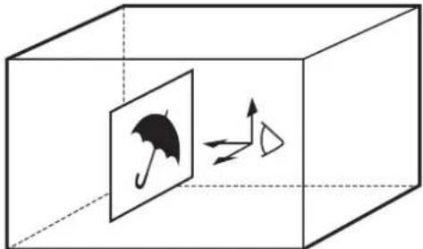
natural_image
Diagram showing a box containing an umbrella icon with directional arrows, no text or symbols presentGlobal coordinates: These are coordinates that are common to all DME channels.
If you want to use global coordinates, you must enable them in the Setup sub menu by setting the Glbl parameter to On (see page 137).

natural_image
Isometric diagram of a 3D cube with four framed photos and directional arrows, no text or symbols present.The positions and rotation angles of images differ depending on the coordinates in which they are defined. To adjust parameters in the Position and Rotation sub menus, select the coordinates by selecting the following sub menus.
(xxx: "M/E DME" appears when you are operating on a transition, and "Keyer" appears when you are operating on a key.)
- xxx L.Source (Local Source) sub menu: Change positions and angles in source coordinates.
- xxx L. Target (Local Target) sub menu: Change positions and angles in target coordinates.

natural_image
Simple geometric diagram showing a square and a dashed line intersecting at an angle (no text or symbols)Change X coordinate

flowchart
graph TD
    A[" "] --> B[" "]
    C[" "] --> D[" "]
Change Y coordinate

natural_image
Simple geometric diagram showing a square and a dashed circle with an arrow, no text or symbols present.Change Z coordinate
Changing the position of an image in source coordinates

natural_image
Simple geometric diagram showing a solid parallelogram intersected by a dashed line (no text or symbols)Change X coordinate

natural_image
Two geometric shapes: a dashed parallelogram and a solid parallelogram, with no text or symbols present.Change Y coordinate

natural_image
Simple geometric diagram showing a parallelogram intersected by a dashed line, with no text or symbols present.Change Z coordinate
Changing the position of an image in target coordinates

natural_image
Simple diagram of a rectangular block with two curved arrows indicating rotational motion (no text or symbols)Rotate around X axis

natural_image
Simple diagram of a square rotating around a vertical axis with curved arrows indicating rotational motion (no text or symbols)Rotate around Y axis
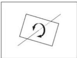
natural_image
Simple diagram with a rectangle containing an arrow and a diagonal line crossing it (no text or symbols)Rotate around Z axis
Changing the rotation angle of an image in source coordinates

natural_image
Simple 3D diagram of a rectangular block with rotational arrows indicating rotation, no text or symbols present.Rotate around X axis

natural_image
Simple diagram showing a tilted rectangle with two curved arrows indicating rotational motion (no text or symbols)Rotate around Y axis

natural_image
Simple geometric diagram with a circle inside a rectangle and an arrow, no text or symbols present.Rotate around Z axis
Changing the rotation angle of an image in target coordinates
Position sub menu parameters
Operations are common for the sub menus of all coordinate systems.
| Operation KnobJoystick | Parameter Settings | ||
| Set the X coordinate (horizontal position) of the image. | F2Move left and right | PX(Position X) | -8.000 to 8.000 |
| Set the Y coordinate (vertical position) of the image. | F3Move up and down | PY(Position Y) | -8.000 to 8.000 |
| Set the Z coordinate (depth position) of the image. | F4Rotate clockwise/ counterclockwise | PZ(Position Z) | -8.000 to 8.000 |
Rotation sub menu parameters
Operations are common for the sub menus of all coordinate systems.
| Operation KnobJoystick | Parameter Settings | |
| Set the rotation angle of the image along the X axis (horizontal rotation). | F2Move left and right | RX (Rotation X) |
| Set the rotation angle of the image along the Y axis (vertical rotation). | F3Move up and down | RY (Rotation Y) |
| Set the rotation angle of the image along the Z axis (depth rotation). | F4Rotate clockwise/ counterclockwise | RZ (Rotation Z) |
Aspect sub menu parameters
Adjust the following parameters to change the aspect ratio of the image.
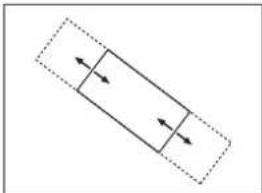
natural_image
Pure diagram of a rectangular object with two arrows inside, enclosed in a dashed rectangle (no text or symbols)Change aspect in the X axis direction

natural_image
Pure geometric diagram with two rectangles and arrows inside a dashed parallelogram (no text or symbols)Change aspect in the Y axis direction
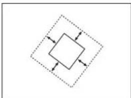
flowchart
graph TD
    A[" "] --> B[" "]
    B --> C[" "]
    C --> D[" "]
    D --> A
Change aspect in the Z axis direction
Change aspects
| Operation Knob | Parameter | Settings | |
| Specify an aspect in the X axis direction. | F2 X (Aspect X) | 0.000 to | 8.000 |
| Specify an aspect in the Y axis direction. | F3 Y (Aspect Y) | 0.000 to | 8.000 |
| Specify an aspect in the Z axis direction. | F4 Z (Aspect Z) | 0.000 to | 8.000 |
Crop sub menu parameters
You can crop the top, bottom, left, and right edges of images by specified amounts. To do so, adjust the following parameters.

Crop example
| Operation Knob | Parameter | Settings | |
| Specify the crop width for the left side. | F1 L (Left Side) 0.0 to 100.0 | ||
| Specify the crop width for the right side. | F2 R (Right Side) 0.0 to 100.0 | ||
| Specify the crop width for the top side. | F3 T (Top Side) 0.0 to 100.0 | ||
| Specify the crop width for the bottom side. | F4 B (Bottom Side) | 0.0 to 100.0 | |
Setup sub menu parameters
Set the following parameters.
| Operation Knob | Parameter | Settings | |
| Enable or disable DME (same function as the DME ENABLE button in the KEYER block (see page 14)). | F1 DME | Off: | Disable DMEOn: Enable DMEa)On-woK: Disable DME for keysb)On-w/K: Enable DME for keysb) |
| Enable or disable global coordinates. | F2 Glbl | Use Globals) | On: Enable Off: Disable |
a) When you are setting up a transition
b) When you are setting up a key
Adding Borders to Images
Use the sub menus of the Border sub menu to do the following.
| Sub menu | Operation |
| xxx Border Colora)(Border Color) | Select whether to add a border to an image, and adjust the color of the border, if added. |
| M/E DME Inner Widthb), Keyer Bord Inner Widc)(Inner Width) | Adjust the widths of the inner sides of the border. |
| M/E DME Outer Widthb), Keyer Bord Outer Widc)(Outer Width) | Adjust the widths of the output sides of the border. |
| M/E DME Border Softb), Keyer Bord Softnessc)(Softness) | Adjust the softness of the inner and outer sides of the border. |
| Sub menu Operation | |
| xxx Bevel Colora)(Bevel Color) | Select whether to add three-dimensional beveled edges to an image, and adjust the color of the beveled edges, if added. |
| xxx Border HLa)(Hilight Setup) | Specify the direction and brightness of the light source that illuminates beveled edges. |
a) xxx: "M/E DME" appears if you are setting up a transition, and "Keyer" appears if you are setting up a key.
b) Transition sub menu
c) Key sub menu
To display Border sub menus
When using the BKDF-901: Press the SHIFT button in the DME/SETUP block, lighting it, and then press the BORDER button.
When using the BKDF-902: Press the BORDER button in the DME/SETUP block.
The most recently used sub menu appears in the display panel.
To switch between sub menus, press the ◀ and ▷ buttons in the numeric keypad.

Border example
Border Color sub menu parameters
Adjust the following parameters to select whether to add a border, and to adjust the color of the border, if added.
| Operation Knob Parameter Settings | |||
| Select whether to add a border to an image. | F1 Bod | (Border Enable) | On: AddOff: Do not add |
| Adjust the luminance of the border. | F2 Lum | (Luminance) | 0.0 to 108.6 |
| Adjust the saturation (color density) of the border. | F3 Sat | (Saturation) 0.0 to | 100 |
| Adjust the hue of the border. | F4 Hue | 0.0 to 359.5 | |
Inner Width sub menu parameters
Adjust the following parameters to adjust the widths of the inner sides of the border.
Note
When you add beveled edges to an image, it is not possible to adjust the widths of the left, right, top, and bottom edges independently. Set any one of the parameter values.
For information about beveled edge settings, see “Bevel Color sub menu parameters” (page 139).
| Operation Knob | Parameter | Settings | |
| Adjust the width of the left inner side border. | F1 L (Left Side) | 0 to 200 | |
| Adjust the width of the right inner side border. | F2 R (Right Side) | 0 to 200 | |
| Adjust the width of the top inner side border. | F3 T (Top Side) | 0 to 200 | |
| Adjust the width of the bottom inner side border. | F4 B (Bottom Side) | 0 to 200 | |
Outer Width sub menu parameters
Adjust the following parameters to adjust the widths of the outer sides of the border.
Note
When you add beveled edges to an image, it is not possible to adjust the widths of the left, right, top, and bottom edges independently. Set any one of the parameter values.
For information about beveled edge settings, see “Bevel Color sub menu parameters” (page 139).
| Operation Knob | Parameter | Settings | |
| Adjust the width of the left outer side border. | F1 L (Left Side) | 0 to 100 | |
| Adjust the width of the right outer side border. | F2 R (Right Side) | 0 to 100 | |
| Adjust the width of the top outer side border. | F3 T (Top Side) | 0 to 100 | |
| Adjust the width of the bottom outer side border. | F4 B (Bottom Side) | 0 to 100 |
Softness sub menu parameters
Adjust the following parameters to adjust the softness of the inner and outer sides of the border.
| Operation Knob | Parameter | Settings | |
| Adjust the softness of the inner side of the border. | F1 InS | (Inner Softness) | 0 to 15 |
| Adjust the softness of the outer side of the border. | F2 OutS | (Outer Softness) | 0 to 15 |
Bevel Color sub menu parameters
Beveled edges make a border appear three dimensional. Adjust the following parameters to select whether to add beveled edges to an image, and to adjust the color of the beveled edges, if added.
Note
It is not possible to adjust the widths of left, right, top, and bottom beveled edges independently.

Beveled edge example
For information about how to adjust beveled edge widths, see “Inner Width sub menu parameters” (page 138) and “Outer Width sub menu parameters” (page 138).
| Operation Knob | Parameter Settings | ||
| Select whether to add beveled edges to an image. | F1 Bvl | (Beveled Enable) | On: AddOff: Do not add |
| Adjust the luminance of the beveled edges. | F2 Lum | (Luminance) 0.0 to | 108.6 |
| Adjust the saturation (color density) of the beveled edges. | F3 Sat | (Saturation) 0.0 to | 100 |
| Adjust the hue of the beveled edges. | F4 Hue | 0.0 to 359.5 | |
Border HL (Highlight Setup) sub menu parameters
Adjust the following parameters to specify the direction and brightness of the light source that illuminates beveled edges.

Beveled edge example
| Operation Knob Parameter Settings | ||
| Set the direction of the light source. (Specify as a position corresponding to a number on the face of an analog clock.)Example: 3 corresponds to the direction from 3 o’clock. | F1 Dir (Hilight Direction) | 0 to 11 |
| Set the mixture ratio of the highlight (lighter) part and the border color. | F2 HL (Hilight Opacity) | 0 to 100.0 |
| Set the mixture ratio of the lowlight (darker) part and the border color. | F3 LL (Lowlight Opacity) | 0 to 100.0 |
Adding Trail Effects, and Changing the Color Type
You can adjust the parameters of the Sub Effects sub menus to add trail effects to images. You can also change the image color type (chroma control).
Trail effect: Adds trail-like afterimages.
Chroma control: Allows you to change the color type of images to sepia, black and white, or negative.

Trail effect example
Make trail and chroma control settings in the following sub menus.
| Sub menu Operation | |
| Trail^a) | Make trail effect settings. |
| Chroma Control Change the | color type. |
a) Shown only on the touch panel
To display the Sub Effects sub menus
Press the SHIFT button in the DME/SETUP block, lighting it, and then press the SUB EFF button.
The most recently used sub menu appears in the display panel.
To switch between sub menus, press the ◀ and ▷ buttons in the numeric keypad.
Trail sub menu parameters
Adjust the following parameters to select whether to add a trail effect, and to adjust the length and color of the trail, if added.
The Trail sub menu has two pages. To switch between pages, press the ◀ and ▷ buttons in the numeric keypad.
(xxx: "M/E" appears if you are setting up a transition, and "KEYER" appears if you are setting up a key.)
xxx Trail 1 (1)
| Operation Knob | Parameter Settings | ||
| Selects whether to add a trail effect. | F1 Typ (Trail Type) Off: Do not add Decay: Add Star: Afterimage disappearing as stardust | ||
| Adjusts the length of the afterimages. | F2 Len (Length) 1 to 6 | ||
xxx Trail 2 (2)
| Operation Knob | Parameter Settings | ||
| Adjusts the luminance of the afterimages. | F2 | Lum (Luminance) | 0.0 to 108.6 |
| Operation Knob Parameter Settings | |||
| Adjusts the saturation (color density) of the afterimages | F3 Sat (Saturation) 0.0 to 100 | ||
| Adjusts the hue of the afterimages. | F4 Hue | 0.0 to 359.5 | |
Chroma Control sub menu parameters
Adjust the following parameters to change the colors of images (Chroma Control).
| Operation | Knob | Parameter | Settings |
| Select the chroma control type. | F1 | T (Type) | Through: Do not change the colorsSepia: SepiaNega: Negative |
| Adjust the saturation (color density) of the image color. | F3 | Sat ^a) (Saturation) | 0.0 to 100 |
| Adjust the image hue. | F4 | Hue | 0.0 to 359.5 |
a) The video becomes black and white if you select Sepia and set Sat to 0.0.
Adjusting 3D DME Warp Effects
You can adjust the parameters of the Warp sub menus to apply 3D DME warp effects to images. These effects allow you to warp, bend, and divide images in many different ways.
Use the sub menus of the Warp sub menu to do the following.
| Sub menu | Operation | Operation target pattern numbers |
| Ripple a) | Adjust the parameters of the Ripple effect. | 100 to 114 |
| xxx Swirl b)(Swirl) | Adjust the parameters of the Swirl effect. | 115, 116 |
| Mosaic a) | Adjust the parameters of the Mosaic effect. | 117, 118 |
| xxx Slats b)(Slats) | Adjust the parameters of the Slats effect (which divides the video into separate strips). | 119 to 124 |
| Lens a) | Adjust the parameters of the Lens effect (which shows the video as if seen through a lens). | 125 to 184 |
| Page Turn a) | Adjust the parameters of the Page Turn effect. | 185 to 223 |
| Sub menu Operation target | pattern numbers | |
| Page Peel a) | Adjust the parameters of the Page Peel effect. | 224 to 231 |
| Splits a) | Adjust the parameters of the Splits effect (which divides the video into separate segments). | 232 to 241 |
| Mirror a) | Adjust the parameters of the Mirror effect. | 242 to 249 |
| xxx Defocus c) (Defocus) | Adjust the parameters of the Defocus effect (which blurs the overall video image). | 252 |
a) Shown only in GUI menu screens
b) xxx: "M/E DME" appears if you are setting up a transition, and "Keyer" appears if you are setting up a key.
c) xxx: "Keyer" appears only if you are setting up a key.
To display the WARP sub menus
When using the BKDF-901: Press the SHIFT button in the DME/SETUP block, turning it off, and then press the WARP button.
When using the BKDF-902: Press the WARP button in the DME/SETUP block.
The most recently used sub menu appears in the display panel.
To switch between sub menus, press the WARP button repeatedly until the sub menu that you want appears.
Ripple sub menu parameters
Adjust the following parameters to adjust the ripple effect.

Ripple effect example
The Ripple sub menu has four pages. To switch between pages, press the ◀ and ▷ buttons in the numeric keypad.
(xxx: “M/E DME” appears if you are setting up a transition, and “Keyer” appears if you are setting up a key.)
xxx Ripple 1 (1)
| Operation Knob | Parameter Settings | ||
| Select the ripple type. | F1 Typ | (Shape Type) | Hor: Horizontal wavesVer: Vertical wavesRot: Rotating wavesCir: Circular ripplePoly: Polygonal rippleStar: Star shaped ripple |
| Select the ripple frequency. | F2 Frq | (Freq) -100.0 | to 100.0 |
| Select the ripple amplitude. | F3 Amp | -2.000 to 2.000 | |
| Select the ripple phase. | F4 Phs | (Phase) -8.000 | to 8.000 |
xxx Ripple 2 (2)
| Operation Knob | Parameter Settings | ||
| Select the wave type. | F1 Way | (Wave Type) | Sine: Sine waveSquare: Square waveTriangle: Triangle waveSaw: Saw waveRandom: Random wave |
| Adjust the rotation of the waves. | F2 Rot | (Rotation) | -8.000 to 8.000 |
| Select the number of apex points of the star shape (when Star is selected). | F3 Pnt | (Points) 2 to 16 | |
| Select the sharpness of the star shape (when Star is selected). | F4 Shp | (Sharpness) | -100.0 to 100.0 |
xxx Ripple 3 (3)
| Operation Knob | Parameter Settings | ||
| Specify the number of sides (when Poly is selected). | F1 Sid | (Sides) 2 to | 32 |
| Specify the X coordinate of the center point of the waves. | F2 PX | (Position X) | -8.000 to 8.000 |
| Specify the Y coordinate of the center point of the waves. | F3 PY | (Position Y) | -8.000 to 8.000 |
Adjust the following parameters to adjust the swirl effect.

Swirl effect example
| Operation Knob | Parameter Settings | |
| Specify the X coordinate of the center of the swirl. | F2 PX (Position X) | -8.000 to 8.000 |
| Specify the Y coordinate of the center of the swirl. | F3 PY (Position Y) | -8.000 to 8.000 |
| Specify the amount of swirling. | F4 Amt (Amount) | -1.000 to 1.000 |
Mosaic sub menu parameters
Adjust the following parameters to adjust the Mosaic effect.

flowchart
graph LR
    A["Multi"] --> B["Format"]
    B --> C["Switcher"]
    D["Multi"] --> E["Format"]
    E --> F["Switcher"]
Mosaic effect example
The Mosaic sub menu has two pages. To switch between pages, press the ◀ and ▷ buttons in the numeric keypad.
(xxx: "M/E DME" appears if you are setting up a transition, and "Keyer" appears if you are setting up a key.)
xxx Mosaic 1 (1)
| Operation Knob | Parameter Settings | ||
| Select the type of Mosaic effect. | F1 Typ | (Type) Nor: | Normal mosaic Rot: Rotated mosaic |
| Specify the aspect ratio of one tile. | F2 Asp | (Aspect) | -8.000 to 8.000 |
| Specify the size of one tile. | F4 Siz | (Size) 0.00 to | 32.00 |
xxx Mosaic 2 (2)
| Operation Knob | Parameter Settings | |
| Specify the X coordinate of the center of the mosaic. | F2 PX (Position X) | -8.000 to 8.000 |
| Specify the Y coordinate of the center of the mosaic. | F3 PY (Position Y) | -8.000 to 8.000 |
| Adjust the rotation of the mosaic. | F4 ROT (Rotation) | -8.000 to 8.000 |
Slats sub menu parameters
Adjust the following parameters to adjust the Slats effect.

Slats effect example
| Operation Knob | Parameter Settings | ||
| Select the way in which the slats are arranged. | F1 Typ | (Shape Type) | Hor: Horizontal Ver: Vertical HV: Horizontal and vertical Rot: Rotated HV-R: Rotated horizontally and vertically |
| Specify the rotation angle of the slats. | F2 Rot | (Rotation) | -8.000 to 8.000 |
| Specify the width of the slats. | F3 Wid | (Slat_Width) | 0.000 to 1.000 |
| Specify the position of the slats. | F4 Amt | (Amount) | -1.000 to 1.000 |
Lens sub menu parameters
Adjust the following parameters to adjust the Lens effect.
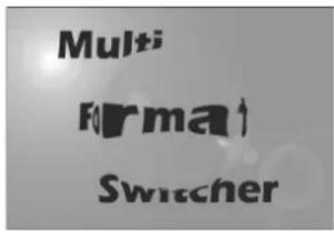
Lens effect example
The Lens sub menu has four pages. To switch between pages, press the ◀ and ▷ buttons in the numeric keypad.
(xxx: “M/E DME” appears if you are setting up a transition, and “Keyer” appears if you are setting up a key.)
xxx Lens 1 (1)
| Operation Knob | Parameter Settings | ||
| Select the lens shape. | F1 Typ | (Shape Type) | Cir: CirclePoly: PolygonStar: Star |
| Specify the rotation angle of the lens. | F2 Rot | (Rotation) | -8.000 to 8.000 |
| Specify the number of apex points (when Poly or Star is selected). | F3 Pnt | (Points) 1 to 16 | 6 |
| Specify the lens focal distance. | F4 Amt | (Amount) | -8.000 to 8.000 |
xxx Lens 2 (2)
| Operation Knob | Parameter Settings | ||
| Select the pattern. | F1 Typ | (Type) Rnd: | RoundLin: LinearMul: Multi |
| Specify the X coordinate of the lens. | F2 PX | (Position X) | -8.000 to 8.000 |
| Specify the Y coordinate of the lens. | F3 PY | (Position Y) | -8.000 to 8.000 |
| Specify the size of the lens. | F4 Siz | (Size) 0.000 to 1.000 | |
xxx Lens 3 (3)
| Operation Knob | Parameter Settings | |
| Specify the tilt of the lens. | F4 Tlt (Tilt) 0.000 to 1.000 | |
Adjust the following parameters to adjust the Page Turn effect.

Page Turn (turn the page up)

Page Roll (roll the page up)
Page Turn effect examples
The Page Turn sub menu has three pages. To switch between pages, press the ◀ and ▷ buttons in the numeric keypad.
(xxx: "M/E DME" appears if you are setting up a transition, and "Keyer" appears if you are setting up a key.)
xxx Page Turn 1 (1)
| Operation Knob | Parameter Settings | ||
| Select the way in which the page is turned. | F1 Pat | (Pattern) | Sing: Turn from one directionQuad: Turn from four directionsMulti: Turn from multiple directionsZipT: Turn from topZipR: Turn from rightZipB: Turn from bottomZipL: Turn from left |
| Specify the rotation angle of the turn. | F2 Rot | (Rotation) | -8.000 to 8.000 |
| Specify the angle of the turn. | F3 Ang | (Peel Angle) | -8.000 to 8.000 |
| Specify the size of the turn. | F4 Amt | (Amount) | -2.000 to 2.000 |
xxx Page Turn 2 (2)
| Operation Knob | Parameter Settings | ||
| Select Page Roll (roll the page up) or Page Turn (turn the page up). | F1 Typ | (Type) Tum: | Page TurnRoll: Page Roll |
| Specify the X coordinate of the center position of the page turn. | F2 PX | (Position X) | -8.000 to 8.000 |
| Specify the Y coordinate of the center position of the page turn. | F3 PY | (Position Y) | -8.000 to 8.000 |
| Specify the number of segments in the turn. | F4 Num | (Num_Segment) | 3 to 31 |
xxx Page Turn 3 (3)
| Operation Knob | Parameter Settings | ||
| Specify the radius of the turn. | F2 Rad | (Radius) | 0.000 to 1.000 |
| Specify the amount of spiraling when the turn width is increased stepwise. | F3 Spl | (Spiral) -8.000 | to 8.000 |
| Specify staggering of the turn position. | F4 Stg | (Stagger) | -8.000 to 8.000 |
Page Peel sub menu parameters
Adjust the following parameters to adjust the Page Peel effect.

Page Peel effect example
The Page Peel sub menu has two pages. To switch between pages, press the ◀ and ▷ buttons in the numeric keypad.
(xxx: "M/E DME" appears if you are setting up a transition, and "Keyer" appears if you are setting up a key.)
xxx Page Peel 1 (1)
| Operation Knob | Parameter Settings | ||
| Select Page Roll (roll the page up) or Page Turn (turn the page up). | F1 Typ | (Type) Tum: | Page TumRoll: Page Roll |
| Specify the rotation angle of the peel. | F2 Rot | (Rotation) | -8.000 to 8.000 |
| Specify the width of a strip when peeling off in strips. | F3 Wid | (Peel_Width) | 0.000 to 1.000 |
| Specify the amount of peeling. | F4 Amt | (Amount) | -2.000 to 2.000 |
xxx Page Peel 2 (2)
| Operation Knob | Parameter Settings | ||
| Specify the tilt of the peel. | F3 Tlt (Tilt) -1.000 to 1.000 | ||
| Specify the size of the distance out to the peel. | F4 Rad (Radius) | 0.000 to 1.000 | |
Splits sub menu parameters
Adjust the following parameters to adjust the Splits effect

Splits effect example
The Splits sub menu has two pages. To switch between pages, press the ◀ and ▷ buttons in the numeric keypad.
(xxx: “M/E DME” appears if you are setting up a transition, and “Keyer” appears if you are setting up a key.)
xxx Splits 1 (1)
| Operation Knob | Parameter Settings | ||
| Select the type of division. | F1 Typ | (Type) 2Way-H: Divided into two parts, left and right2Way-V: Divided into two parts, top and bottom4Way: Divided into four partsMulti: Divided into multiple parts | |
| Specify the rotation angle of the divisions (when Multi is selected). | F2 Rot | (Rotation) | -8.000 to 8.000 |
| Adjust the distance between the parts when dividing into a spiral. | F3 Spl | (Spiral) -8.000 to 8.000 | |
| Adjust the displacement between parts when parts are staggered. | F4 Stg | (Stagger) | -8.000 to 8.000 |
xxx Splits 2 (2)
| Operation Knob | Parameter Settings | ||
| Specify the number of divisions (when Multi is selected). | F1 Num (Num_Segment) | 3 to 31 | |
| Specify the X coordinate of the center point of the division (when Multi is selected). | F2 PX (Position X) | -8.000 to 8.000 | |
| Specify the Y coordinate of the center point of the division (when Multi is selected). | F3 PY (Position Y) | -8.000 to 8.000 | |
| Specify the amount of movement of the divided area. | F4 Amt (Amount) | -2.000 to 2.000 | |
Mirror sub menu parameters
Adjust the following parameters to adjust the Mirror effect.

Mirror effect example
The Mirror sub menu has two pages. To switch between pages, press the ◀ and ▷ buttons in the numeric keypad.
(xxx: "M/E DME" appears if you are setting up a transition, and "Keyer" appears if you are setting up a key.)
xxx Mirror 1 (1)
| Operation Knob | Parameter Settings | ||
| Specify the type of division. | F1 Typ | (Type) 2Way0 | (2 way, 0)2Way1 (2 way, 1)2Way2 (2 way, 2)2Way3 (2 way, 3)4Way0 (4 way, 0)4Way1 (4 way, 1)4Way2 (4 way, 2)4Way3 (4 way, 3)Multi (multiple divisions) |
| Specify the rotation angle of the mirror (when Multi is selected). | F2 Rot | (Rotation) | -8.000 to 8.000 |
xxx Mirror 2 (2)
| Operation Knob | Parameter Settings | |
| Specify the number of mirrors (when Multi is selected). | F1 Num (Num_Segment) | 1 to 31 |
| Specify the X coordinate of the center point of the mirror. | F2 PX (Position X) | -8.000 to 8.000 |
| Specify the Y coordinate of the center point of the mirror. | F3 PY (Position Y) | -8.000 to 8.000 |
Defocus sub menu parameters
Adjust the following parameter to specify the level (amount of blurring) of the Defocus effect.

Defocus effect example
| Operation Knob | Parameter Settings | ||
| Adjust the amount of blurring. | F4 Amt | (Amount) | 0 to 100 |
Adding Lighting Effects
You can adjust the parameters of the Light sub menu to add lighting effects to images.

Example of a lighting effect applied to a ripple effect
Use the sub menus of the Light sub menu to do the following.
| Sub menu Operation | |
| xxx DME L.Typea)(Type) | Select the type of light source. |
| Light 1 and 2b) | Specify the size of the light source,its position, and the color ofhighlighted parts. |
a) xxx: "M/E DME" appears if you are setting up a transition, and "Keyer" appears if you are setting up a key.
b) Shown only in GUI menu screens
To display the Light sub menus
When using the BKDF-901: Press the SHIFT button in the DME/SETUP block, lighting it, and then press the LIGHT button.
When using the BKDF-902: Press the LIGHT button in the DME/SETUP block.
The most recently used sub menu appears in the display panel.
To switch between sub menus, press the ◀ and ▷ buttons in the numeric keypad.
To select the type of light source in the Type sub menu
| Operation Knob Parameter Settings | |||
| Select the type of light source. (Select Off if you do not want to add a lighting effect to the image.) | F1 Typ | (Type) Off: No light source 1-HL: Highlight 1 2-HL: Highlight 1 HL/LL: Highlight and low-light | |
Light 1 and Light 2 sub menu parameters
When you have selected 1-HL or 2-HL in the Type sub menu, use the Light 1 and Light 2 sub menus to adjust the size and position of the light source and to adjust the color of highlighted parts.
The Light 1 and Light 2 sub menus each have two pages. To switch between pages, press the ◀ and ▶ buttons in the numeric keypad.
(xxx: "M/E DME" appears if you are setting up a transition, and "Keyer" appears if you are setting up a key.)
xxx L1/xxx L2 Position (Position)
| Operation Knob | Parameter Settings | ||
| Specify the size of the light source (plane light source) | F1 Siz | (Size) 0.0 to 100.0 | |
| Specify the X coordinate of the center point of the light source. | F2 PX | (Position X) | -1.000 to 1.000 |
| Specify the Y coordinate of the center point of the light source. | F3 PY | (Position Y) | -1.000 to 1.000 |
| Specify the Z coordinate of the center point of the light source. | F4 PZ | (Position Z) | -1.000 to 1.000 |
Lxxx L1/xxx L2 Color (Color)
| Operation | Knob | Parameter | Settings |
| Specify the mixing ratio between the color of the highlighted parts and the base color. | F1 Opac (Opacity) | 0 to 100.0 | |
| Operation Knob | Parameter Settings | ||
| Adjust the luminance of the highlighted parts. | F2 Lum | (Luminance) | 0.0 to 108.6 |
| Adjust the saturation of the highlighted parts. | F3 Sat | (Saturation) | 0 to 100.0 |
| Adjust the hue of the highlighted parts. | F4 Hue | 0.0 to 359.5 | |
Registering User Patterns
You can use the User sub menu to register DME wipe patterns that you have customized.
1 Customize a DME wipe pattern using one of the sub menus.
2 When using the BKDF-901: Press the SHIFT button in the DME/SETUP block, turning it off, and then press the USER button.
When using the BKDF-902: Press the USER button in the DME/SETUP block.
The User sub menu appears in the display panel.
3 Rotate the F1 knob in the Display Panel/Menu Control Block to select the number under which to register the pattern.
| Knob | Parameter Description Settings | ||
| F1 Usr | (User Pattern) | Number under which to register the user pattern | 300 to 339a) |
a) An asterisk (*) appears after the number when a user pattern has already been registered.
4 Press the F2 knob and hold it down for one second or longer.
The pattern is registered under the number selected in step 3.
To unregister a pattern
Rotate the F1 knob in the Display Panel/Menu Control Block to select the pattern number to unregister, and then press the F4 knob and hold it down for one second or longer.
Applying Masks to Keys
You can use mask patterns to hide defects or unneeded parts of keys.
Use the Key Mask sub menu of the Keyer menu to select mask patterns and to specify the location and size of the pattern.
Note
Box masks are the only masks that can be applied to downstream keys (see page 150). Other mask patterns cannot be selected for downstream keys.
To enable key masks

1 When using the BKDF-901: Depending on the key that you want to mask, press one of the KEY1 to KEY4 buttons in the KEY DELEGATION block, lighting it.
When using the BKDF-902: Depending on the key that you want to mask, press one of the KEY1 to
KEY4 buttons in the key/AUX bus control block, lighting it.
2 Press the MASK button in the KEYER section, lighting it.
Key masks are enabled, and the Key Mask sub menu appears in the display panel.
To select a mask pattern and change the position or size of the pattern
Adjust the parameters of the Key Mask sub menu.
| Operation Kncb Parameter Settings | |||
| Select a pattern. | F1 Pat (Mask Pattern) | 0 to 33, 38 to 40, 42 to 48, 65 to 69, 75 to 79, 85 to 94, 105 to 114 | |
| Specify the X coordinate of the center point of the pattern. | F2 PX (Pattern Center X) | -1.000 to 1.000 | |
| Specify the Y coordinate of the center point of the pattern. | F3 PY (Pattern Center Y) | -1.000 to 1.000 | |
| Adjust the size of the pattern. | F4 Siz (Pattern Size) | 0.0 to 100.0 | |
Adding Edges to Keys
You can use the Edge Shadow sub menu of the Keyer menu to add various types of edges to keys.
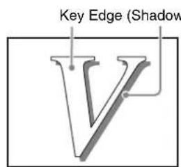
Edge example (Shadow)
Note
Edges cannot be added when you have selected chroma key as the key type, and edges cannot be added to downstream keys.
To enable shadow edges

1 When using the BKDF-901: Depending on the key to which you want to add the edges, press one of the KEY1 to KEY4 buttons in the KEY DELEGATION block, lighting it.
When using the BKDF-902: Depending on the key to which you want to add the edges, press one of the KEY1 to KEY4 buttons in the key/AUX bus control block, lighting it.
2 Press the EDGE SHADOW button in the KEYER block, lighting it.
Edges (Shadows) are enabled, and the Edge Shadow sub menu appears in the display panel.
Edge Shadow sub menu parameters
Use the sub menus of the Edge Shadow sub menu to do the following.
| Sub menu Operation | |
| Edge Type (Type) Select | the edge type, and specify properties such as the edge width and softness. |
| Edge Color (Color) Adjust | the edge color. |
| Edge Position (Position) | Adjust the edge position. |
To switch between sub menus, press the ◀ and ▷ buttons in the numeric keypad.
Edge Type (Type) sub menu parameters
| Operation Kncb Parameter Settings | |||
| Select the edge type. | F1 Typ | (Type) Normal: | Normal edgesOutline: OutlineExtrude: Drop shadowShadow: Shadow |
| Adjust the edge width. | F2 Wid | (Width) 1 to 8 | |
| Adjust the edge softness (amount of blurring). | F3 Sft | (Softness) 0.0 to | 100.0 |
| Operation | Knob | Parameter | Settings |
| When Extrude is selected, specify the edge direction. (Specify as a position corresponding to a number on the face of an analog clock.)Example: 3 corresponds to the direction from 3 o'clock. | F4 Dir (Direction) 0 to 11 |
Edge Color (Color) sub menu parameters
| Operation | Knob | Parameter | Settings |
| Adjust the luminance of the edges. | F2 Lum | (Luminance) 0.0 | to 108.6 |
| Adjust the saturation (color density) of the edges. | F3 Sat | (Saturation) 0.0 | to 100.0 |
| Adjust the hue of the edges. | F4 Hue | 0.0 | to 359.5 |
Edge Position (Position) sub menu parameters
| Operation | Knob | Parameter | Settings |
| When Shadow is selected, specify the X coordinate of the position where the shadow is added. | F2 | PX (Position X) | -100.0 to 100.0 |
| When Shadow is selected, specify the Y coordinate of the position where the shadow is added. | F3 | PY (Position Y) | -100.0 to 100.0 |
Masking Downstream Keys with Box Masks
You can use the Box Mask sub menu of the Keyer menu to apply box masks to downstream keys.
To enable the Box Mask sub menu

1 When using the BKDF-901: Depending on the key that you want to apply the box masks, press the DSK1 or DSK2 button in the KEY DELEGATION block, lighting it.
When using the BKDF-902: Depending on the key to which you want to apply the box masks, press the DSK1 or DSK2 button in the key/AUX bus control block, lighting it.
2 Press the MASK button in the KEYER block, lighting it.
Box mask is enabled, and the Box Mask sub menu appears in the display panel.
To adjust the position of the box mask
Adjust the parameters of the Box Mask sub menu.
| Operation Knob Parameter Settings | |||
| Specify the position of the left edge of the box mask. | F1 L (BoxMask Left) | 0 to 1024 | |
| Specify the position of the right edge of the box mask. | F2 R (BoxMask Right) | 0 to 1024 | |
| Specify the position of the top edge of the box mask. | F3 T (BoxMask Top) | 0 to 1024 | |
| Specify the position of the bottom edge of the box mask. | F4 B (BoxMask Bottom) | 0 to 1024 | |
Registering Operations and Settings
Chapter
You can register a set of control panel settings as a single event, and then recall the settings simply by recalling the event. These settings include the selection of the background video, transition settings, key settings, and DME settings. You can register up to eight pages of events, with 12 events on each page, for a total of 96 events. You can also register sequences consisting of up to 31 keyframes, each of which represents a set of control panel settings for a single frame of video. Sequences allow you to transition gradually from the settings in one keyframe to the settings in the next keyframe, according to a specified interpolation mode. You can save up to 100 sequences. Use the Sequence Event menu (see page 179) for event and sequence operations.
Event Operations
Use the following procedures to register and recall the current control panel settings.
Registering Events
To register an event, make the control panel settings that you want to register, and then proceed as follows.

1 Press the EVENT button in the numeric keypad.
The numeric keypad enters event mode.
The 0 to 9, dot (.), and CANCEL buttons become event registration buttons, and buttons to which events have been registered light in green
The most recently used sub menu appears in the display panel.
2 If the INSERT button is lit, press it to turn it off.
The Event Data sub menu appears.
3 Rotate the F1 knob to select a page.
You can select a page from among the event pages P1 to P8.
4 Press the STORE button.
The button lights in red to indicate that the switcher has entered event storage mode.
5 Press the event registration button to which you want to register the current settings.
The current settings are stored in the memory of the control panel.
To save all event data to a USB flash drive
1 Carry out steps 1 and 2 of "Registering Events" (page 151).
2 Connect a USB flash drive to the USB MEMORY connector.
3 Press the F2 knob and hold it down for one second or longer.
All event data is stored to the USB flash drive.
Recalling Events
Use the following procedure to recall a stored event.

1 Press the EVENT button in the numeric keypad.
The numeric keypad enters event mode.
The RECALL button lights in red, and the 0 to 9, dot (.) , and CANCEL buttons become event registration buttons. Buttons to which events have been registered light in green
The most recently used sub menu appears in the display panel.
You can also specify that only settings of a certain type should be recalled. For the operating procedure, see "To recall an event while specifying certain types of settings" (page 153).
2 If the INSERT button is lit, press it to turn it off.
The Event Data sub menu appears.
3 Rotate the F1 knob to select a page.
4 Press the event registration button to which the event that you want to recall has been assigned.
The event registered for the pressed button is recalled, and all of the settings in the event are restored on the control panel.
To recall an event while specifying certain types of settings
Use the following procedure if you want to recall an event but want to recall only certain types of settings instead of all settings registered in the event.
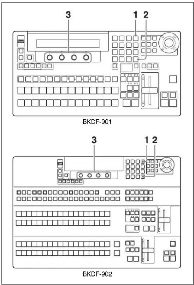
1 Press the EVENT button in the numeric keypad.
The numeric keypad enters event mode.
2 If the INSERT button is unlit, press it to turn it on.
The Event Target sub menu appears in the display panel.
3 Rotate the F1 to F4 knobs to select the types of settings to recall.
When using the BKDF-901
| Knob | Parameter | Description Settings | |
| F1 | BUS M/E settings | other than keyer settings | BUS On: Include M/E settings other than keyer settingsBUS Off: Do not include M/E settings other than keyer settingsP-P Hold: Include settings other than keyer settings and PROGRAM/PRESET settings |
| F2 | Keyer Keyer | settings | Keyer On: Include keyer settingsKeyer Off: Do not include keyer settings |
| F3 | DSK DSK | settings | DSK On: Include DSK settingsDSK Off: Do not include DSK settings |
| F4 | Still | settings a) | Still Off: Do not include Still settingsStill On: Still1 to Still4 settingsStill1: Still1 settings onlyStill2: Still2 settings onlyStill3: Still3 settings onlyStill4: Still4 settings only |
a) The data registered in the event is the file numbers of the images in Still1 to Still4 memory. Image data is not registered.
When using the BKDF-902
| Knob | Parameter | Description Settings | |
| F1 | BUS M/E settings | other than keyer settings, and PROGRAM/PRESET settings | BUS On: Include M/E settings other than keyer settings, and PROGRAM/PRESET settingsBUS Off: Do not include M/E settings other than keyer settings, and PROGRAM/PRESET settingsME On: Include M/E settings onlyPP On: Include PROGRAM/PRESET settings onlyP-P Hold: Include settings other than PROGRAM/PRESET settings |
| F2 | Keyer Keyer | settings | Keyer On: Include keyer settingsKeyer Off: Do not include keyer settings |
| F3 | DSK DSK | settings | DSK On: Include DSK settingsDSK Off: Do not include DSK settings |
| F4 | Still | settings a) | Still Off: Do not include Still settingsStill On: Include Still1 to Still4 settingsStill1: Include Still1 settings onlyStill2: Include Still2 settings onlyStill3: Include Still3 settings onlyStill4: Include Still4 settings only |
a) The data registered in the event is the file numbers of the images in Still1 to Still4 memory. Image data is not registered.
4 Carry out steps 2 and following of “Recalling Events” (page 152).
The event registered for the pressed button is recalled. From among the settings in the event, only those settings that were specified in step 3 are restored on the control panel.
Note
The type selections made in step 3 are retained until the control panel is powered off. They are applied to all subsequent event recalls. If you want to recall different types of settings, carry out the procedure again from steps 1 through 4.
To recall all event data from a USB flash drive
1 Carry out steps 1 and 2 of “Recalling Events” (page 152).
2 Connect the USB flash drive that contains the data that you want to recall to the USB MEMORY connector.
3 Rotate the F3 knob to select USB as the storage location of the data that you want to recall.
4 Press the F3 knob and hold it down for one second or longer.
All event data is recalled.
To recall events in page units from the USB flash drives
You can recall multiple events at once by recalling them in page units.
To recall events in page units, use the F1 knob instead of the F3 knob in step 3 of "To recall all event data from a USB flash drive" (page 154). Rotate the F1 knob to select the page, and then, with the SHIFT button in the DME/SETUP block (when using the BKDF-901) or the KEY SRC button in the key/AUX bus control block (when using the BKDF-902) held down, press the F3 knob and hold it down for one second or longer.
The events on the specified page are recalled.
Deleting Events
Use the following procedure to delete registered events.

BKDF-901

BKDF-902
1 Press the EVENT button in the numeric keypad.
The numeric keypad enters event mode.
The most recently used sub menu appears in the display panel.
2 If the INSERT button is lit, press it to turn it off.
The Event Data sub menu appears.
3 Rotate the F1 knob to select a page.
4 Press the STORE button.
5 With the SHIFT button in the DME/SETUP block (when using the BKDF-901) or the KEY SRC button in the key/AUX bus control block (when using the BKDF-902) held down, press the event registration button to which the event that you want to delete has been assigned.
The button changes from lit in green to not lit, and the event registered for that button is deleted.
To delete events in page units
You can delete multiple registered events at once by deleting them in page units.
In event mode, select a page, and then press the F4 (Initial) knob and hold it down for one second or longer.
To recall events from an editor
Setting the communications protocol to GVG100 (see page 162) allows specifying an E-FILE (event file) number to recall individual events from the BVE-2000. The following figure shows the correspondence between the events on each page and E-FILE numbers, using the arrangement of buttons on the numeric keypad.
Numeric keypad
Event
| keypad | Page P1 | P2 P3 P4 | P5 | |||||
| 7 | 8 | 9 | E-FILE | 50 51 52 62 63 64 74 | 75 76 86 87 | 88 98 | ||
| 4 | 5 | 6 | 53 54 55 65 66 67 77 | 78 79 89 90 | 91 | |||
| 1 | 2 | 3 | 56 57 58 68 69 70 80 | 81 82 92 93 | 94 | |||
| 0 | N | e | w D | 59 60 61 71 72 73 83 | 84 85 95 96 | 97 | ||
Events numbers 50 to 98 can be specified from the BVE-2000. (The BVE-2000 can operate numbers up to 99, but number 99 is reserved for "Init Panel".)
On how to use the BVE-2000, refer to the User's Guide supplied with the BVE-2000.
Sequence Operations
You can register a series of video settings as a sequence. Use the following procedure.
Creating Sequences
Use the following procedure to create a sequence.


1 Create the video that you want to register as the first keyframe in the sequence.
Registering the desired video as an event in advance may be convenient, because it allows you to restore a set of video settings to the control panel simply by recalling the event.
2 Press the SEQ button in the numeric keypad.
The numeric keypad enters sequence mode. The most recently used sub menu appears in the display panel.
3 Press the ◀◀ and ▷▶ buttons in the numeric keypad until the Seq File sub menu appears.
4 Press the NEW button.
Sequence memory is cleared.
5 Press the INSERT button.
The current control panel settings are registered as the first keyframe of the sequence.
6 Press the SEQ button.
The numeric keypad exits sequence mode.
7 Create the video that you want to register as the next keyframe.
8 Press the SEQ button again to switch to sequence mode, and then press the INSERT button.
The video created in step 7 is registered as the next keyframe.
Repeat steps 6 to 8 to register all of the keyframes that you want in the sequence.
9 Rotate the F1 knob to select the file in which you want to save the sequence.
You can select file numbers from 00 to 99.
10 Rotate the F2 knob to select the sequence storage destination.
You can select either the switcher control panel (CP) or a USB flash drive.
11 Press the STORE button.
The sequence is stored in the selected file in the selected storage destination.
Recalling Sequences
Use the following procedure to recall a sequence that you have created.

BKDF-901
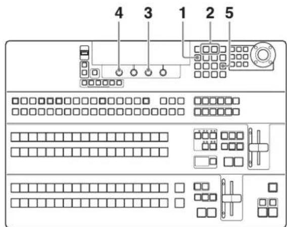
BKDF-902
1 Press the SEQ button in the numeric keypad.
The numeric keypad enters sequence mode. The most recently used sub menu appears in the display panel.
2 Press the ◀◀ and ▷▶ buttons in the numeric keypad until the Seq File sub menu appears.
3 Rotate the F3 knob to select the storage destination of the sequence that you want to recall.
You can select either the switcher control panel (CP) or a USB flash drive.
4 Rotate the F1 knob to select the file that contains the sequence that you want to recall.
Tip
An asterisk (*) appears after the number of file that contains a sequence.
5 Press the RECALL button.
The sequence in the selected file is recalled.
To display the video of the first keyframe when a sequence is recalled
The normal procedure for recalling a sequence does not recall the video of the first keyframe. If you want to display the video of the first keyframe when a sequence is recalled, proceed as follows.
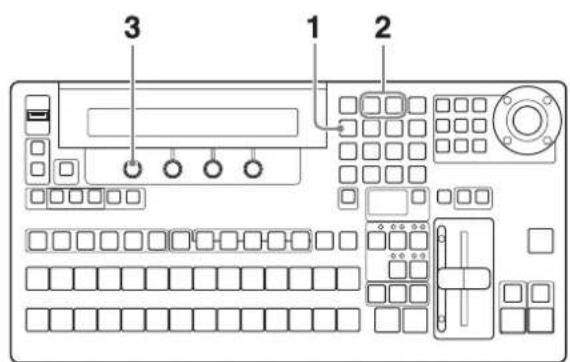
BKDF-901

BKDF-902
1 Press the SEQ button in the numeric keypad.
The numeric keypad enters sequence mode. The most recently used sub menu appears in the display panel.
2 Press the ◀◀ and ▶▶ buttons in the numeric keypad until the Seq Setup sub menu appears.
3 Rotate the F1 knob to specify whether to recall the first keyframe.
Onl (Only Recall): Do not recall the first keyframe. Rew (Recall+Rewind): Recall the first keyframe.
To replace the current video settings with the settings of a registered sequence
Before recalling the sequence, proceed as follows.

1 Press the SEQ button in the numeric keypad.
The numeric keypad enters sequence mode. The most recently used sub menu appears in the display panel.
2 Press the ◀◀ and ▷▶ buttons in the numeric keypad until the Seq Setup sub menu appears.
3 Rotate the F2, F3, and F4 knobs to select whether to change M/E, keyer, and DSK settings when the sequence is played.
When using the BKDF-901
| Knob Parameter Description Settings | |||
| F2 BUS | M/E settings | other than keyer settings | On: Do not change the current settings.Off: Replace the current settings with the sequence settings. |
| F3 Keyer | Keyer | settings | |
| F4 DSK | Downstream | key settings | |
When using the BKDF-902
| Knob Parameter Description Settings | |||
| F2 BUS | M/E settings | other than keyer settings, and PROGRAM/PRESET settings | BUS Off:Replace M/E, and PROGRAM/PRESET settings with the sequence settings.BUS On: Do not change M/E, and PROGRAM/PRESET settings.ME On: Do not change the current M/E settings.Replace PROGRAM/PRESET settings with the sequence settings.PP On: Do not change the current PROGRAM/PRESET settings.Replace M/E settings with the sequence settings. |
| F3 M/E Keyer | settings | On: Do not change the current settings.Off: Replace the current settings with the sequence settings. | |
| F4 DSK | DSK settings | ||
When a sequence is recalled, the settings of the recalled sequence are reflected, but they are reflected to the currently displayed video instead of to the video that was selected at the time when the sequence was registered.
Playing Sequences
You can use the following four buttons in the numeric keypad to play a sequence after recalling it.

flowchart
graph TD
    A["MENU 7"] --> B["<< 8"]
    B --> C[">> 9"]
    C --> D["EVENT -"]
    E["SFQ 4"] --> F["<< 5"]
    F --> G[">> 6"]
    G --> H["STORE"]
    I["1"] --> J["LOOP 2"]
    J --> K["DIR 3"]
    K --> L["RECALL"]
    M["0"] --> N["NEW ."]
    N --> O["DILERT CANCEL"]
    O --> P["INSERT ENTER"]
    Q["DIR button"] --> R["LOOP button"]
    S["▶ (play/stop) button"] --> T["II (pause/restart) button"]
II (pause/restart) button: Pauses play when pressed during play, and restarts play from the paused position when pressed again.
▶■ (play/stop) button: Starts play when pressed, and stops play when pressed again.
LOOP button: Selects loops play. If you want loop play, press this button to light it before starting play.
DIR button: Reverses the play direction.
Editing Sequences
After recalling a sequence, you can edit it by changing parameters and by adding or deleting keyframes.
To change parameters
Use the Seq Edit sub menu to change parameters.
To display the Seq Edit sub menu
Press the SEQ button in the numeric keypad.
The most recently used sub menu appears in the display panel.
Press the ◀◀ and ▶▶ buttons in the numeric keypad until the Seq Edit sub menu appears.
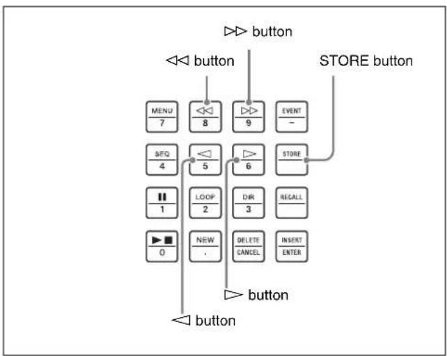
flowchart
graph TD
    A["button"] --> B["menu 7"]
    A --> C["8"]
    A --> D["9"]
    A --> E["EVENT -"]
    A --> F["STORE button"]
    G["button"] --> H["SEQ 4"]
    G --> I["LOOP 2"]
    G --> J["DIR 3"]
    G --> K["REGALL"]
    L["button"] --> M["NEW ."]
    L --> N["DELETE CANCEL"]
    L --> O["INSERT ENTER"]
The Seq Edit sub menu displays the total number of keyframes (Total) registered in the currently recalled sequence, and the number of the current keyframe (Cur). The current keyframe is the keyframe at the current display position. You can press the ◀ and ▷ buttons to move the current keyframe.

The following parameters can be changed.
| Knob | Parameter | Description Settings | |
| F1 | Play^a) | Sequence execution (play) time | 1 to 3200 |
| F2 Brk | b) Pause at | each keyframe | On, Off |
| F3 | Ival^a) | Interval 1 to 999 | |
| F4 Mode Interpolation | on mode Point, Line, Curve | ||
a) The interval is a relative value with respect to the execution time. It changes whenever the execution time changes.
b) Setting this to On results in a pause between individual keyframes, which is convenient if you want to add or delete keyframes.
When you have finished changing parameters, press the STORE button to save the changes.
Note
Unless you save them, changes to parameters are lost when the switcher is powered off. Always save the sequence whenever you change sequence parameters.
For information about how to save sequences, see "Creating Sequences" (page 156).
To add keyframes
You can add new keyframes at any point in a sequence. To add a keyframe, recall a sequence and then proceed as follows.

1 Press the ◀ and ▷ buttons to move to the point where you want to add a keyframe.
If you want to add a new keyframe at the end of the sequence, move to the last current keyframe.
2 Press the SEQ button in the numeric keypad.
The switcher exits sequence mode.
3 Create the video that you want to add as a keyframe.
4 Press the SEQ button again to switch to sequence mode.
5 Press the INSERT button.
The newly created video is added as a new keyframe, and the keyframe that was previously at that position is shifted toward the end of the sequence, along with all subsequent keyframes.
To delete keyframes
To delete a keyframe from a sequence, recall the sequence and then proceed as follows.
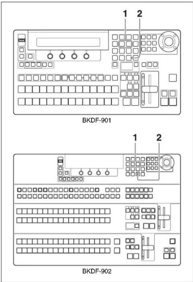
1 Press the ◀ and ▷ buttons to move to the position of the keyframe that you want to delete.
2 Press the DELETE button.
Deleting Sequences
To delete a stored sequence, recall that sequence and then press the F4 knob and hold it down for one second or longer.
External Control Interface Settings
Chapter
Serial Interface Settings
Before connecting an editor or AUX bus remote controller, you must set up the serial interface by making communication settings.
To make communication settings, use the Serial sub menu of the Setup menu. The Serial sub menu has the following sub menus.
| Sub menu Operation | |
| Protocol Set the communication protocol | |
| Baudrate Set the baud rate | |
| Parity Set the parity bit |
To show the sub menus

In the External Connections and Power block, press the EDITOR button twice in quick succession.
The most recently used sub menu appears in the display panel.
To switch between sub menus, press the ◀ and ▷ buttons in the numeric keypad.
Note
Always make the communication settings in these sub menus before connecting a serial communications device.
Communications Protocol Settings
Adjust the following parameters in the Protocol sub menu to specify the communications protocol.
| Knob | Parameter | Description Settings | a) |
| F1 1 R | S-422A, port | 1 Specify the serial communications device to be connected from among the following: GVG100, BVS3000, HVS-AUX | |
| F2 2 R | S-422A, port | 2 GVG100, BVS3000, HVS-AUX | |
| F3 3 R | S-422A, port | 3 GVG100, BVS3000, HVS-AUX | |
| F4 4 R | S-422A, port | 4 (editor) | GVG100, BVS3000, HVS-AUX |
a) For each parameter, rotate the corresponding knob to select the serial communications device to be connected. Select “---” if you do not want to select a device.
Baud Rate Settings
Adjust the following parameters in the Baudrate sub menu to set the baud rate.
| Knob | Parameter | Description Settings | |
| F1 1 R | S-422A, port | 1 9600, 19200, 38400 | |
| F2 2 R | S-422A, port | 2 9600, 19200, 38400 | |
| F3 3 R | S-422A, port | 3 9600, 19200, 38400 | |
| F4 4 R | S-422A, port | 4 (editor) | 9600, 19200, 38400 |
Parity Bit Settings
Adjust the following parameters in the Parity sub menu to set the parity bit.
| Knob | Parameter | Description Settings | |
| F1 1 R | S-422A, | port 1 | None: Do not use a parity bitOdd: Odd parityEven: Even parity |
| F2 2 R | S-422A, | port 2 | None: Do not use a parity bitOdd: Odd parityEven: Even parity |
| F3 3 R | S-422A, | port 3 | None: Do not use a parity bitOdd: Odd parityEven: Even parity |
| Knob | Parameter | Description Settings | |
| F4 4 | RS-422A, | port 4 (editor) | None: Do not use a parity bitOdd: Odd parityEven: Even parity |
GPI Input Settings
You can use GPI input signals to control the switcher from other devices. Pins 1 to 6 of the GPI IN connector are for GPI input. You can assign GPI input signals to these pins to control the functions listed below.
For more information about the pins of the GPI IN connector, see "Pin Assignments" (page 211). For more information about signal connection, see "Example Connection of GPI Input" (page 214).

- M/E Trn: Execute an M/E transition.
- M/E Cut: Execute an M/E cut transition.
• M/E Mix: Change the M/E transition type to mix. - M/E Wipe: Change the M/E transition type to wipe.
- M/E DME: Change the M/E transition type to DME wipe.
- M/E FAM: Change the M/E transition type to full-additive mix.
- M/E NAM: Change the M/E transition type to non-additive mix.
- P/P Trn: Execute a PROGRAM/PRESET transition (only when using the BKDF-902).
- P/P Cut: Execute a PROGRAM/PRESET cut transition (only when using the BKDF-902).
- P/P Mix: Change the PROGRAM/PRESET transition type to mix (only when using the BKDF-902).
- P/P Wipe: Change the PROGRAM/PRESET transition type to wipe (only when using the BKDF-902).
- DSK 1 Cut: Execute a DSK 1 cut transition.
- DSK 1 Mix: Execute a DSK 1 mix transition.
- DSK 2 Cut: Execute a DSK 2 cut transition.
- DSK 2 Mix: Execute a DSK 2 mix transition.
• FTB: Execute a fade to black.
• SEQ Play: Play a sequence.
To change GPI input settings
Use the GPI sub menu.
To display the GPI sub menu
In the External Connections and Power Block, press the GPI button twice in quick succession.

The most recently used sub menu appears in the display panel.
To switch between sub menus, press the ◀ and ▷ buttons in the numeric keypad.
To change settings
Adjust the following parameters.
When using the BKDF-901
| Knob | Parameter | Description Settings | |
| F1 GPI | GPI input pin number | 1 to 16 | |
| F2 F | GPI input | function | M/E Trn, M/E Cut, M/EMix, M/E Wipe, M/EDME, M/E FAM, M/ENAM, DSK1 Cut, DSK1Mix, DSK2 Cut, DSK2Mix, FTB, SEQ Play |
When using the BKDF-902
| Knob | Parameter | Description Settings | |
| F1 GPI | GPI input pin number | 1 to 16 | |
| F2 F | GPI input | function | M/E Trn, M/E Cut, M/EMix, M/E Wipe, M/EDME, M/E FAM, M/ENAM, P/P Trn, P/P Cut,P/P Mix, P/P Wipe,DSK1 Cut, DSK1 Mix,DSK2 Cut, DSK2 Mix,FTB, SEQ Play |
Tally Output Settings
This switcher can output 32 different tally signals. You can assign the following tally output signals to tally/GPI output pins of the TALLY/GPI OUT connector.
For more information about the pins of the TALLY/GPI OUT connector, see "Pin Assignments" (page 211). For more information about signal connection, see "Example Connection of Tally/GPI Output" (page 214).

• R-BLK: Red tally to BLACK
• R-In01 to 24: Red tally to In01 to In24
• R-Stl1 to 4: Red tally to Stl1 to Stl4
• R-Mat1 to 4: Red tally to Mat1 to Mat4
- R-Rsv01 to R-Rsv07 (or 06) ^1) : Reserved for future expansion
• R-ME: Red tally to M/E (only when using the BKDF-902)
• G-BLK: Green tally to BLACK
• G-In01 to 24: Green tally to In01 to In24
• G-Stl1 to 4: Green tally to Stl1 to Stl4
• G-Mat1 to 4: Green tally to Mat1 to Mat4
• G-Rsv01 to G-Rsv06 (or 05) ^2) : Reserved for future expansion
- P1a y : See "To set the GPI output" (page 166)
• G-ME: Green tally to M/E (only when using the BKDF-902)
• Alarm: Alarm
1) When using the BKDF-901: R-Rsv01 to R-Rsv07
When using the BKDF-902: R-Rsv01 to R-Rsv06
2) When using the BKDF-901: G-Rsv01 to G-Rsv06
When using the BKDF-902: G-Rsv01 to G-Rsv05
To change tally output settings
Use the Tally sub menu.
To display the Tally sub menu
In the External Connections and Power Block, press the GPI button twice in quick succession.
GPI button

natural_image
Line drawing of a computer control panel layout with no text or symbolsBKDF-901
GPI button
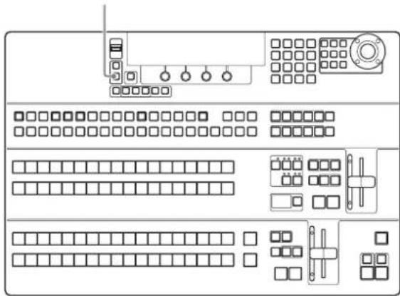
natural_image
Pure electrical circuit lines without any symbolsBKDF-902
The most recently used sub menu appears in the display panel.
To switch between sub menus, press the ◀ and ▷ buttons in the numeric keypad.
To change settings
Adjust the following parameters.
When using the BKDF-901
| Knob | Parameter | Description Settings | |
| F1 Tally | Tally output | pin number | 1 to 32 |
| F2 F Tally type R-Blk, R-In01 to R-In24,R-Stl1 to R-Stl4, R-Mat1to R-Mat4, R-Rsv01 toR-Rsv07, G-Blk, G-In01to G-In24, G-Stl1 toG-Stl4, G-Mat1 toG-Mat4, G-Rsv01 toG-Rsv06, Play, Alarm | |||
When using the BKDF-902
| Knob | Parameter | Description Settings | |
| F1 Tal | yTally output pin number | 1 to 32 | |
| Knob | Parameter | Description Settings |
| F2 F | Tally type R-Blk, R-In01 to R-In24,RStl1 to RStl4, R-Mat1to R-Mat4, R-Rsv01 toR-Rsv06, R-ME, G-Blk,G-In01 to G-In24,G-Stl1 to G-Stl4,G-Mat1 to G-Mat4,GRsv01 to GRsv05,Play, G-ME, Alarm | |
GPI Output Settings
This switcher can output GPI signals from the TALLY/GPI OUT connector. You can use the GPI output for timing control when you capture images from a playback device for keying.
For more information about the pins of the TALLY/GPI OUT connector, see “Pin Assignments” (page 211). For more information about signal connection, see “Example Connection of Tally/GPI Output” (page 214).

To set the GPI output
Use the Tally sub menu to select a pin from 32 pins of the TALLY/GPI OUT connector and assign "Play" function. Rotate the F1 knob to select the pin number, and rotate the F2 knob to select Play.
For more information about the Tally sub menu, see "To change tally output settings" (page 164).

Other Operations and Settings
Chapter
8
Backing Up Data
You can use the Data Backup sub menu of the Setup menu to back up, recall, and clear the various types of data used by the switcher.
Backup or recall: Save backup data to a USB flash drive connected to the USB MEMORY connector, or recall the data as required.
Clear: Clear the data saved in the USB flash drive connected to the USB MEMORY connector or in the memory of the control panel.
The following types of data can be targeted.
- All data: System data and file data
- System data: Data such as events, I/O settings, initial values, and status data
- File data: Still image file data stored in the control panel, user pattern data, and sequence data.
To back up, recall, and clear data, use sub menus of the Data Backup sub menu.
| Sub menu Operation | |
| All Backup Back up, | recall, and clear all data |
| System Backup Back | up, recall, and clear system data |
| File Backup Back up, | recall, and clear file data |
To display the Data Backup sub menus

1 When using the BKDF-901: If the SHIFT button in the DME/SETUP block is not lit, press it to light it.
When using the BKDF-902: Skip to step 2.
2 Press the SYSTEM button.
The most recently used sub menu appears in the display panel.
3 Press the ◀ and ▷ buttons in the numeric keypad until the desired sub menu appears.
Backing Up, Restoring, and Clearing All Data
In the All Backup sub menu, check the following parameters and then execute the backup.
| Knob | Parameter | Description Settings | |
| F1 | Store | Back up all data USB | |
| F2 | Recall | Recall all data USB | |
| F4 | Clear | Clear all data CP |
To back up all data to a USB flash drive
Connect a USB flash drive, and then press the F1 knob and hold it down for one second or longer.
Note
If there is not enough free memory on the USB flash drive, the backup is cancelled and an error message appears.
To recall all data from a USB flash drive
Connect a USB flash that contains the backup data, and then press the F2 knob and hold it down for one second or longer.
To clear all data from the memory of the control panel
Press the F4 knob and hold it down for one second or longer.
Backing Up, Restoring, and Clearing System Data
In the System Backup sub menu, set the following parameters, and then execute the backup.
To back up all data to a USB flash drive
| Knob | Parameter | Description Settings | |
| F1 Store | Backup system data | USB | |
| F2 Recall | Recall system data | USB | |
| F3 No | System data management number | Sys0 to Sys9 | |
| F4 Clear | Clear system data | USB | |
To back up system data to a USB flash drive
Connect a USB flash drive, rotate the F3 knob to select a system data management number (Sys0 to Sys9), and then press the F1 knob and hold it down for one second or longer.
Notes
- If there is not enough free memory on the USB flash drive, the backup is cancelled and an error message appears.
- The backup file names corresponding to the ten system management numbers Sys0 to Sys9 are the ten file names “a” to “j”.
- An asterisk (*) appears beside a system management number when backup data under that number already exists on the USB flash drive. If you select a number with an asterisk, the existing data is overwritten when you press the F1 knob and hold it down for one second or longer.
To recall system data from a USB flash drive
Connect a USB flash that contains backup system data, rotate the F3 knob to select a system data management number (Sys0 to Sys9), and then press the F2 knob and hold it down for one second or longer.
To clear system data from a USB flash drive
Connect a USB flash that contains backup system data, rotate the F3 knob to select a system data management number (Sys0 to Sys9), and then press the F4 knob and hold it down for one second or longer.
Backing Up, Restoring, and Clearing File Data
In the File Backup sub menu, set the following parameters, and then execute the backup.
| Knob | Parameter | Description | Settings |
| F1 | Store Backup | up file data USB | |
| F2 | Recall Recall | ll file data USB | |
| F3 | Type | File data type | Stl, Seq, Usr |
| F4 | Clear Location | where data to be cleared is stored | USB, CP |
To back up file data to a USB flash drive
Connect a USB flash drive and then proceed as follows.
1 Rotate the F3 knob to select the type of file data.
Stl: Data saved as still image files
Seq: Data saved as sequence files
Usr: User pattern data
2 Press the F1 knob and hold it down for one second or longer.
Note
If there is not enough free memory on the USB flash drive, the backup is cancelled and an error message appears.
To recall backup file data from a USB flash drive Connect a USB flash that contains backup file data and then proceed as follows.
1 Rotate the F3 knob to select the type of file data.
Stl: Data saved as still image files
Seq: Data saved as sequence files
Usr: User pattern data
2 Press the F2 knob and hold it down for one second or longer.
To clear file data from a USB flash drive or control panel memory
1 Rotate the F3 knob to select the type of file data.
Stl: Data saved as still image files
Seq: Data saved as sequence files
Usr: User pattern data
2 Rotate the F4 knob to select the memory that you want to clear.
USB: USB flash drive connected to the USB MEMORY connector
CP: Memory of the switcher's control panel
3 Press the F4 knob and hold it down for one second or longer.
Updating the System
Use the Update sub menu of the Setup menu to update the system software, and to turn the display panel cursor icon on or off.
To display the Update sub menu
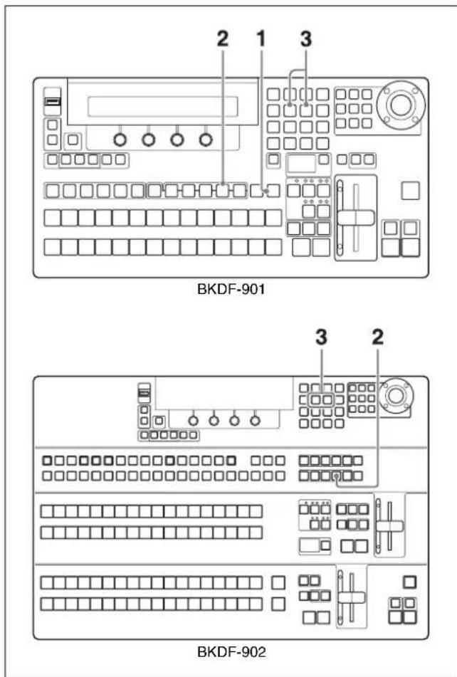
1 When using the BKDF-901: If the SHIFT button in the DME/SETUP block is not lit, press it to light it.
When using the BKDF-902: Skip to step 2.
2 Press the SYSTEM button.
The most recently used sub menu appears in the display panel.
3 Press the ◀ and ▷ buttons in the numeric keypad until the Update sub menu appears.
To update the system
In the Update sub menu, adjust the following parameters, and then execute the operation.
| Knob | Parameter | Description Settings | |
| F1 CP | Update the | control panel software. | - |
| F3 TG | Update firmware. | DSP, CPU, | Main_IO, XPT, KEYER, Comb, DME, MV, SDI_I, SDI_O AI^a) , AO^a) , DVI\_I^a) , DVI\_O^a) |
| F4 Cursor Turn the | GUI menu cursor on or off. | - | |
a) Reserved for future expansion
To display or hide the GUI menu cursor
Press the F4 knob and hold it down for one second or longer.
To update the software from the Update sub menu
For information about software updates contact a Sony service representative.
Status Information
The Status sub menu of the Setup menu allows you to check alarms, software versions, and the status of the option boards installed in the switcher.
To display the Status sub menus

1 When using the BKDF-901: If the SHIFT button of the DME/SETUP block is not lit, press it to light it.
When using the BKDF-902: Skip to step 2.
2 Press the STATUS button.
The most recently used sub menu appears in the display panel.
3 Press the ◀ and ▷ buttons in the numeric keypad until the desired sub menu appears.
Option Board Information
The Board In/Out/Op1/Op2 sub menus allows you to check whether option boards are installed.
| Knob Parameter Description Settings | |||
| F1 Displays | information about the board(s) in input expansion slots. | s: 4SDI Input Boarda: SD analog input boardd: DVI input board-: Not installed | |
| F2 Displays | information about the board(s) in output expansion slots. | s: 4SDI Output Boarda: SD analog output boardd: DVI output board-: Not installed | |
| F3 Displays | information about the board(s) in the DME1 and DME2 sockets. | dme: 2CH DME Board-: Not installed | |
| F4 Displays | information about the board(s) in the MV1 and MV2 sockets. | mv: Multi Viewer Board-: Not installed | |
Software Version Information
The Firmware sub menu allows you to check software version information.
The software name and version information appear in the display areas of the F1 to F4 knobs.
Alarms
The Alarm sub menu allows you to check the various alarms.
| Knob Parameter Description Settings | |||
| F1 PWR | Displays | information about the installed power supply unit(s) in the processor unit. | Single A: Only one standard power supply unit is installed.Single B: Only one optional power supply unit is installed.Dual: Both a standard and an optional power supply unit are installed. |
| Knob Parameter Description Settings | |||
| F2 | PS | Displays alarm status of the power supply unit(s) in the processor unit. | okth@operation is normal.ng: An error has been detected. |
| F3 FN | Displays the | alarm status of the fan. | ok: Operation is normal.ng: An error has been detected. |
| F4 CP | Displays | information about the installed power supply unit(s) in the control panel. | ok: Operation is normal.ng: An error has been detected. |
Overview
When you put the switcher into 3D mode, you can switch 3D video and add keys.
- In 3D mode, signals for the left eye and the right eye (referred to here simply as left and right signals) are handled as pairs.
- The available keys are KEY1, KEY2, DSK1, and DSK2. However, note that an operation is performed on only DSK1 and DSK2, that the DSK1 operation and DSK2 operation are linked to KEY1 and KEY2, respectively, and that DME effects cannot be applied to keys and chroma keys.
The following table lists the signals that you can use in 3D mode.
| Signal type Use in 3D mode | |
| Signals input to SDI IN connectors 1 to 24 | For 3D, separate signals are used for left and right.For applications other than 3D (titles and so on), the same signals are used for left and right. |
| Internal black signals | |
| Internal color matte signals | |
| Images stored in still image memory (STL1 to STL4) | You can choose either of the following.2D mode: Use the same images for left and right.3D mode: Use separate image for left and right. |
I/O of 3D Mode Signals
Input example
For 2D, input the same signal for left and right.

For 3D, input separate signals for left and right.
DFS-900M processor unit rear panel
3D signal input destinations
Input left signals to odd numbered connectors and right signals to even numbered connectors.
2D signal input destinations
For titles and so on, input the same signal for left and right.
Signal output and connection destinations
Left signals are output from PGM Out, and right signals are output from AUX1.
You can view 3D video by connecting these outputs to L and R input connectors of a 3D monitor.
3D Mode Signal Assignments
Signals that are selectable with the cross-point selection buttons can be assigned for use in 3D mode.
The following tables list the signal assignments available when you have changed the 3D System Mode setting from the factory default setting to on.
For information about how to change signal assignments, see “Assigning video input signals to cross-point selection buttons” (page 76).
When using the BKDF-901
(In the following table, "IN1" refers to the input signal connected to the SDI IN 1 connector.)
| Cross-point buttons | Video signals Video | signal (specified with SHIFT button) | ||
| Left Right | Left Right | |||
| 1 IN 1 IN 2 IN 17 IN 18 | ||||
| 2 IN 3 IN 4 IN 19 IN 20 | ||||
| 3 IN 5 IN 6 IN 21 IN 22 | ||||
| 4 IN 7 IN 8 IN 23 IN 24 | ||||
| 5 IN 9 IN 10 Black signal Black signal | ||||
| 6 IN 11 IN 12 Black signal Black signal | ||||
| 7 IN 13 IN 14 Black signal Black signal | ||||
| 8 IN 15 IN 16 Black signal Black signal | ||||
| 9 | STL1 a) | STL1 a) | Color matte signal 1 | Color matte signal 1 |
| 10 | STL2 a) | STL2 a) | Color matte signal 2 | Color matte signal 2 |
| 11 | STL3 a) | STL3 a) | Color matte signal 3 | Color matte signal 3 |
| 12 | STL4 a) | STL4 a) | Color matte signal 4 | Color matte signal 4 |
a) When using still images in 3D mode, assign separate images to left and right.
When using the BKDF-902
(In the following table, "IN1" refers to the input signal connected to the SDI IN 1 connector.)
| Cross-point buttons | Video signals Video signal (specified with SHIFT button) | ||
| Left Right | Left Right | ||
| 1 IN 1 IN 2 | Black signal | Black signal | |
| 2 IN 3 IN 4 | Black signal | Black signal | |
| 3 IN 5 IN 6 | Black signal | Black signal | |
| 4 IN 7 IN 8 | Black signal | Black signal | |
| 5 IN 9 IN 10 | Black signal | Black signal | |
| Cross-point buttons | Video signals Video | signal (specified with SHIFT button) | ||
| Left Right | Left Right | |||
| 6 IN 11 IN 1 | 2 Black signal Black | signal | ||
| 7 IN 13 IN 1 | 4 Black signal Black | signal | ||
| 8 IN 15 IN 1 | 6 Black signal Black | signal | ||
| 9 IN 17 IN 1 | 8 Black signal Black | signal | ||
| 10 IN 19 IN | 20 Black signal Black | signal | ||
| 11 IN 21 IN | 22 Black signal Black | signal | ||
| 12 IN 23 IN | 24 Black signal Black | signal | ||
| 13 | STL1^a) | STL1^a) | Color matte signal 1 | Color matte signal 1 |
| 14 | STL2^a) | STL2^a) | Color matte signal 2 | Color matte signal 2 |
| 15 | STL3^a) | STL3^a) | Color matte signal 3 | Color matte signal 3 |
| 16 | STL4^a) | STL4^a) | Color matte signal 4 | Color matte signal 4 |
a) When using still images in 3D mode, assign separate images to left and right.
System Settings
1 When using the BKDF-901: If the SHIFT button in the DME/SETUP block is not lit, press it to light it. When using the BKDF-902: Skip to step 2.
2 Press the SYSTEM button.
The most recently used sub menu appears in the display panel.
3 Press the < or > button in the numeric keypad until the 3D SYSTEM sub menu appears.
Switching to 3D Mode
Set the following parameters with knob 1.
| Knob | Parameter | Description Settings | |
| F1 3D | Mode Operate | in 3D mode | On, Off |
Selecting the 2D/3D Mode of Stored Still Images
When the switcher is operating in 3D mode, you can use images stored in still image memory in either 2D or 3D mode.
Select the mode by setting the following parameters with knobs 2 and 3.
| Knob Parameter Description Settings | |||
| F2 3D Stll1 & Still2 Stll1 image mode 2D, 3D | |||
| F3 3D Stll3 & Still4 Stll2 image mode 2D, 3D |
When you select 2D, the same signal is used for left and right.
When you select 3D, separate signals are used for left and right.
Signal Assignments for Using Still Images in 3D Mode
When you set the still image mode to 3D, the signal assignments of the cross-point buttons (see the table shown on the previous page) are changed.
When using the BKDF-901
When you select 3D with the F2 knob or F3 knob, the signal assignments of cross-point buttons 9 and 10 or 11 and 12 are changed as follows.
| Cross-point buttons Video signals | |||
| Left Right | |||
| 9 STL1 | STL2 | ||
| 10 | STL2 | STL1 | |
| 11 | STL3 | STL4 | |
| 12 | STL4 | STL3 | |
When using the BKDF-902
When you select 3D with the F2 knob or F3 knob, the signal assignments of cross-point buttons 13 and 14 or 15 and 16 are changed as follows.
| Cross-point buttons Video signals | ||
| Left Right | ||
| 13 | STL1 | STL2 |
| 14 | STL2 | STL1 |
| 15 | STL3 | STL4 |
| 16 | STL4 | STL3 |
3D Mode Operations
The following limitations apply to operations in 3D mode.
- The available transition types are limited to cut and mix by button operations.
- When an operation on a DSK is performed, M/E keys behave in the same way.
You cannot directly operate M/E keys.
The DSK1 and DSK2 values set in the menu are applied to KEY1 and KEY2, respectively.
- Events created in 3D mode can be used only in 3D mode.
- Sequence functions are not available.
- A function which captures still images from input signals is available only for the left signals.
When using the BKDF-901
Some buttons are not available (the buttons shown in black in the following figure).

| Operating block Unavailable buttons | |
| KEYER block DME ENBL, | CK, MASKEDGE SHADOW(EXT and SELF are disabled for KEY1 and KEY2.) |
| KEY DELEGATION block | KEY3, KEY4 |
| Transition block TRANS P | VW, KEY1 to KEY4WIPE (FAM), DME (NAM)PRIORITY, FTB |
When using the BKDF-902
Instead of operating with the M/E Cross-Point Bus block and the M/E Transition block, use the PROGRAM/PRESET Cross-Point Bus block and the PROGRAM/PRESET Transition block.
Some buttons are not available (the buttons shown in black in the following figure).

| Operating block Unavailable buttons | |
| KEYER block DME EN | BL, CK, MASKEDGE SHADOW(EXT and SELF are disabled for KEY1 and KEY2.) |
| KEY DELEGATIONblock | KEY3, KEY4 |
| M/E rows All buttons and the fader lever | |
| PROGRAM/PRESETCross-Point Bus block | M/E buttons |
| KEY DELEGATIONblock | KEY3, KEY4 |
| DSK/Fade to BlackControl block | FTB |
Appendix
Menu Structure
The following menu tree shows the configuration of the switcher's menu system and lists the menu items that appear in the display panel. Names in parentheses are the names that appear in GUI menu screens, which are displayed when you connect an optional PC monitor or an optional touch panel monitor.
For more information about GUI menu screens, see "Menu Operations in the GUI Menus" (page 64).
Transition Menu (for Transition, Wipe, and DME Settings)

flowchart
graph TD
    A["Level 1 Level 2 Level 3 Level 4"] --> B["Transition Rate (Rate) PGM (PGM Rate)"]
    B --> C["(Wipe) Wipe Pattern (Pattern) Pat (Pattern No.)"]
    C --> D["DSK (DSK Rate)"]
    C --> E["FTB (FTB Rate)"]
    C --> F["Wipe Border Color (Border Color)"]
    F --> G["Wid (Border Width)"]
    F --> H["Soft (Border Softness)"]
    F --> I["Src (Border Source)"]
    C --> J["Wipe Modify (Modify) Asp (Aspect)"]
    J --> K["Pat (Pattern No.)"]
    J --> L["Lum (Luminance)"]
    J --> M["Sat (Saturation)"]
    J --> N["Hue (Hue)"]
    C --> O["User (User) Usr (User Pattern)"]
    O --> P["PX (Center Position X)"]
    O --> Q["PY (Center Position Y)"]
    O --> R["Ang (Angle)"]
    O --> S["Usr Store (User Wipe Date Store)"]
    C --> T["(Continued) Usr Clear (User Wipe Date Clear)"]

flowchart
graph TD
    A["Level 1"] --> B["DME"]
    A --> C["Fader Limit (Fader Limit) Val (Fader Limit)"]
    A --> D["Delay C-Delay Rate"]

    B --> E["M/E DME Pattern (Pattern)a)<br>    (DME Basic)a)<br>    (Border)<br>    (Sub Effects)a)<br>    (Warp)a)<br>    (Light)a)<br>    User(User)<br>    <br>    C --> F[AT-Delay Rate"]
a) For details, see "DME Menu (for DME Settings)" (page 183).
Keyer Menu (for Key Settings)

flowchart
graph TD
    A["(Keyer) (Key1 to Key4) (Key Type) (External Key)"] --> B["External Key 1 (1)"]
    B --> C["KIns (Ext Key Insert)"]
    B --> D["KSrc (Ext Key Source)"]
    B --> E["GN (Ext Key Gain)"]
    B --> F["Clip (Ext Key Clip)"]
    B --> G["External Key 2 (2)"]
    G --> H["Opac (Opacity)"]
    G --> I["Inv (Key Invert)"]
    B --> J["(Self Key) Self Key 1 (1) KIns (Self Key Insert)"]
    J --> K["GN (Self Key Gain)"]
    J --> L["Clip (Self Key Clip)"]
    B --> M["(Chroma Key) CK Auto (Auto) KIns (Key Insert)"]
    M --> N["PX (Position X)"]
    M --> O["PY (Position Y)"]
    M --> P["Auto (Auto CK)"]
    M --> Q["(Manual) CK Manual 1 (1) Hue (Hue)"]
    Q --> R["GN (Gain)"]
    Q --> S["Clip (Clip)"]
    Q --> T["CK Manual 2 (2) Y (Offset Y)"]
    T --> U["C (Offset C)"]
    T --> V["K (Offset K)"]
    T --> W["(Continued)"]
    W --> X["Ang (Angle)"]

Appendix

| Level 1 | Level 2 | Level 3 | Level 4 | Level 5 | Level 6 | Level 7 |
| Self Key 2 (2) Opac (Opacity) Inv (Key Invert) | ||||||
| Box Mak (Box Mask) | L (BoxMask Left) R (BoxMask Right) T (BoxMask Top) B (BoxMask Bottom) | |||||
a) For details, see "DME Menu (for DME Settings)" (page 183).
Still Store Menu (for Still Image Settings)

flowchart
graph TD
    A["(Still Store) Download Still (Download) Dst (Destination)"] --> B["Image Capture (Capture) Frz (Freeze Mode)"]
    B --> C["Export Still (Export) Fmt (File Format)"]
    C --> D["Delete Still (Delete) File (File)"]
    B --> E["File (Source)"]
    B --> F["DL (Download)"]
    C --> G["File (File)"]
    C --> H["Cap.Start (Capture)"]
    C --> I["File (File)"]
    C --> J["(Over Write) a)"]
    C --> K["Export (Export)"]
    D --> L["Del (Delete)"]
a) The selection items that appear in the display panel are OverWrite and NewFile.
Sequence Event Menu (for Sequence and Event Registration)
| Level 1 | Level 2 | Level 3 | Level 4 |
| (Sequence Event) (Sequence) Seq File (File) File (Sequence Name) | |||
| Store (Store Sequence) | |||
| Recall (Recall Sequence) | |||
| Del (Delete Sequence) | |||
| Seq Edit (Edit) | Play (Play Time) | ||
| Brk (Break each Step) | |||
| Ival (Step Interval Time) | |||
| (Continued) | Mode (Interpolation Mode) | ||
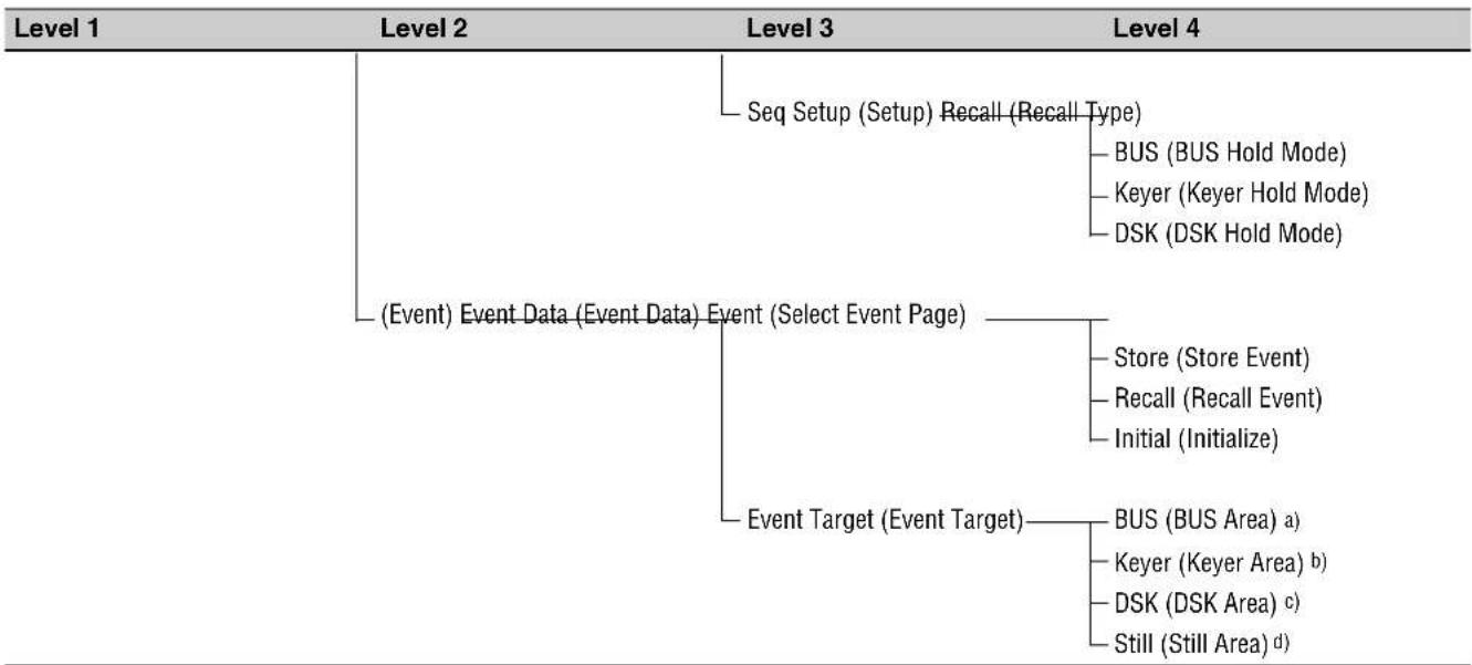
flowchart
graph TD
    A["Level 1"] --> B["(Event) Event Data (Event Data) Event (Select Event Page)"]
    B --> C["Event Target (Event Target)"]
    C --> D["Seq Setup (Setup) Recall (Recall Type)"]
    D --> E["BUS (BUS Hold Mode)"]
    D --> F["Keyer (Keyer Hold Mode)"]
    D --> G["DSK (DSK Hold Mode)"]
    C --> H["Store (Store Event)"]
    C --> I["Recall (Recall Event)"]
    C --> J["Initial (Initialize)"]
    C --> K["BUS (BUS Area) a"]
    C --> L["Keyer (Keyer Area) b"]
    C --> M["DSK (DSK Area) c"]
    C --> N["Still (Still Area) d"]
a) The selection items that appear in the display panel are BUS On, BUS Off, and P-P Hold.
b) The selection items that appear in the display panel are Keyer On and Keyer Off.
c) The selection items that appear in the display panel are DSK On and DSK Off.
d) The selection items that appear in the display panel are Still 1, Still 2, Still 3, Still 4, Still On and Still Off.
Setup Menu (for System Settings)
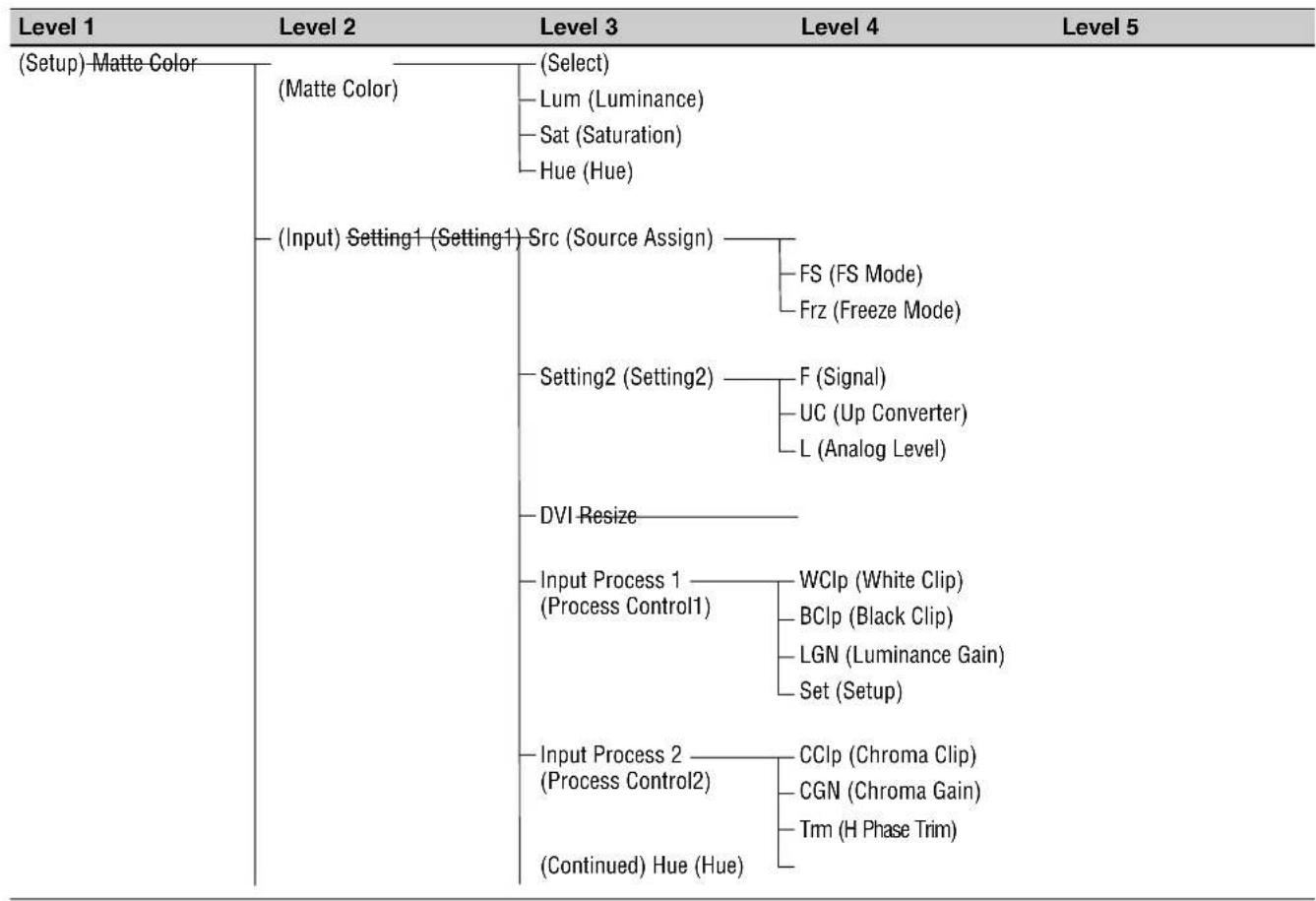
flowchart
graph TD
    A["(Setup) Matte Color"] --> B["(Matte Color)"]
    B --> C["(Select)"]
    C --> D["Lum (Luminance)"]
    D --> E["Sat (Saturation)"]
    E --> F["Hue (Hue)"]
    A --> G["(Input) Setting1 (Setting1) Src (Source Assign)"]
    G --> H["FS (FS Mode)"]
    G --> I["Frz (Freeze Mode)"]
    G --> J["Setting2 (Setting2)"]
    J --> K["F (Signal)"]
    J --> L["UC (Up Converter)"]
    J --> M["L (Analog Level)"]
    G --> N["DVI Resize"]
    N --> O["Input Process 1 (Process Control1)"]
    O --> P["WCIp (White Clip)"]
    O --> Q["BCIp (Black Clip)"]
    O --> R["LGN (Luminance Gain)"]
    O --> S["Set (Setup)"]
    G --> T["Input Process 2 (Process Control2)"]
    T --> U["CCIp (Chroma Clip)"]
    T --> V["CGN (Chroma Gain)"]
    T --> W["Tm (H Phase Trim)"]
    T --> X["(Continued) Hue (Hue)"]

flowchart
graph TD
    A["Level 1"] --> B["(Output) Aux (Aux) Aux (Aux Number)"]
    A --> C["DVI DVI Out Format"]
    A --> D["(MV) (MV1,MV2) MV1 Window, MV2"]
    A --> E["(System) Type (Type) VF (Video Format)"]

    B --> B1["Signal Rename (Signal Rename)"]
    B --> B2["Save (File Save) Download (File Download)"]

    C --> C1["Src (Source) Ihb (Inhibit)"]
    C --> C2["Output (Setting) Aux (Aux Number)"]
    C --> C3["F (Signal) DC (Down Converter) L (Level)"]
    C --> C4["Aspect Frequency"]
    C --> C5["Other (Other) DSK PVW (DSK PVW)"]

    D --> D1["Window (Window)"]
    D --> D2["Typ (Type) Win (Window) Sig (Signal) Name (Signal Name)"]

    E --> E1["MV1 OA Tally, MV2 OA Tally (OA Tally)"]
    E --> E2["OA (OA Tally) Lum (Luminance) Sat (Saturation) Hue (Hue)"]

    E --> E3["MV1 Next Tally, MV2 Next Tally (Next Tally)"]
    E --> E4["Next (Next Tally) Lum (Luminance) Sat (Saturation) Hue (Hue)"]

Appendix

flowchart
graph TD
    A["Level 1"] --> B["Level 2"]
    B --> C["Level 3"]
    C --> D["Level 4"]
    D --> E["Level 5"]

    A --> F["Time Adj. (Time Adj.) Set (Date_Time Set.)"]
    F --> G["H (Date Adj. Hour)"]
    F --> H["M (Date Adj. Minute)"]
    F --> I["S (Date Adj. Second)"]

    A --> J["(Status) Board In/Out/Op1/Op2 (Board)"]
    J --> K["(Input Option) a)"]
    J --> L["(Output Option) a)"]
    J --> M["(DME Option) a)"]
    J --> N["(MV Option) a)"]

    A --> O["(Firmware) Firmware 1 (1) GUI (GUI)"]
    O --> P["DSP (DSP)"]
    O --> Q["CPU (CPU)"]

    O --> R["Firmware 2 (2) Main (MAIN_IO)"]
    R --> S["XPT (XPT)"]
    R --> T["Key (KEYER)"]
    R --> U["Com (Combiner)"]

    O --> V["Firmware 3 (3) DME (DME)"]
    V --> W["MV (MV)"]
    V --> X["SI (SDI_I)"]
    V --> Y["SO (SDI_0)"]

    O --> Z["Firmware 4 (4) AI (AI)"]
    Z --> AA["AO (AO)"]
    Z --> AB["DI (DVI_I)"]
    Z --> AC["DO (DVI_0)"]

    A --> AD["Alarm (Alarm)-PWR (Power Supply)"]
    AD --> AE["PS (Power Alarm)"]
    AD --> AF["FN (Fan Alarm)"]

    A --> AG["(Serial) Protocol (Protocol)-1 (RS-422A 1CH)"]
    AG --> AH["2 (RS-422A 2CH)"]
    AG --> AI["3 (RS-422A 3CH)"]
    AG --> AJ["4 (RS-422A 4CH(Editor))<br><br>    A --> AK[Baudrate (Baudrate)-1 (RS-422A 1CH)"]
    AK --> AL["2 (RS-422A 2CH)"]
    AK --> AM["3 (RS-422A 3CH)"]
    AK --> AN["(Continued) 4 (RS-422A 4CH(Editor))"]

flowchart
graph TD
    A["Level 1"] --> B["Level 2"]
    B --> C["Parity (Parity Bit) 1 (RS-422A 1CH)"]
    B --> D["2 (RS-422A 2CH)"]
    B --> E["3 (RS-422A 3CH)"]
    B --> F["4 (RS-422A 4CH(Editor))"]
    A --> G["(GPIO Tally) GPI (GPI) GPI (GPI Pin Number)"]
    G --> H["F (GPI Function)"]
    G --> I["Tally (Tally) Tally (Tally Pin Number)"]
    I --> J["F (Tally Function)"]
    A --> K["(Data Backup) All Backup (All Data) Store (Store All Data)"]
    K --> L["Recall (Recall All Data)"]
    K --> M["Clear (All Data Clear)"]
    A --> N["System Backup (System Data)"]
    N --> O["Store (Store System Data)"]
    N --> P["Recall (Recall System Data)"]
    N --> Q["No (System Data Select)"]
    N --> R["Clear (System Data Clear)"]
    A --> S["File Backup (File Data) Store (Store File Data)"]
    S --> T["Recall (Recall File Data)"]
    S --> U["Typ (File Data Type)"]
    S --> V["Clear (File Data Clear)"]
    A --> W["Update (Update) GP (GP Update)"]
    W --> X["Cal. (Calibration)"]
    W --> Y["TG (Firmware Update)"]
    W --> Z["Cursor (Cursor Icon)"]
a) The slot numbers of installed boards appear in the display panel.
DME Menu (for DME Settings)
This is a list of items related to DME settings that appear in the Transition menu and the Keyer menu. In the Transition menu, the "xxx" in the list is replaced by "M/E DME". In the Keyer menu, "xxx" is replaced by "Keyer".
| Level 1 | Level 2 | Level 3 | Level 4 | Level 5 |
| (DME) M/E DME Pattern, Keyer DME Patt a) (Pattern) (DME Basic) | — Pat (Pattern No.) | |||
| (Position) | xxx L.Source (Local Source) (Continued) | PX (Position X) PY (Position Y) PZ (Position Z) | ||

Appendix
| Level 1 | Level 2 | Level 3 | Level 4 | Level 5 |
| xxx L.Target (Local Target) | PX (Position X) PY (Position Y) PZ (Position Z) | |||
| xxx G.Source (Global Source) | PX (Position X) PY (Position Y) PZ (Position Z) | |||
| xxx G.Target (Global Target) | PX (Position X) PY (Position Y) PZ (Position Z) | |||
| (Rotation) xxx L.Source | (Local Source) | RX (Rotation X) RY (Rotation Y) RZ (Rotation Z) | ||
| xxx L.Target (Local Target) | RX (Rotation X) RY (Rotation Y) RZ (Rotation Z) | |||
| xxx G.Source (Global Source) | RX (Rotation X) RY (Rotation Y) RZ (Rotation Z) | |||
| xxx G.Target (Global Target) | RX (Rotation X) RY (Rotation Y) RZ (Rotation Z) | |||
| xxx Aspect (Aspect) X (Aspect X) | ||||
| Y (Aspect Y) | ||||
| Z (Aspect Z) | ||||
| Crop (Crop) L (Left Side) | ||||
| R (Right Side) | ||||
| T (Top Side) | ||||
| B (Bottom Side) | ||||
| xxx Setup (Setup) DME (DME) | ||||
| Glbl (Use Globals) | ||||
| (Border) xxx Border Color | (Border Color) (Continued) Hue (Hue) | Bod (Border Enable) Lum (Luminance) Sat (Saturation) | ||
| M/E DME Inner Width, Keyer Bord Inner Wid b) (Inner Width) | L (Left Side) R (Right Side) T (Top Side) B (Bottom Side) | |||
| M/E DME Outer Width, Keyer Bord Outer Wid c) (Outer Width) | L (Left Side) R (Right Side) T (Top Side) B (Bottom Side) | |||
| M/E DME Border Soft, Keyer Bord Softness d) (Softness) | InS (Inner Softness) OutS (Outer Softness) | |||
| xxx Bevel Color (Bevel Color) | Bvl (Beveled Enable) Lum (Luminance) Sat (Saturation) Hue (Hue) | |||
| xxx Border HL (Hilight Setup) | Dir (Hilight Direction) HL (Hilight Opacity) LL (Lowlight Opacity) | |||
| (Sub Effects) | (Trail) | xxx Trail 1 (1) Typ (Trail Type) Len (Length) xxx Trail 2 (2) Lum (Luminance) Sat (Saturation) Hue (Hue) | ||
| Chroma Control (Chroma Control) | T (Type) Sat (Saturation) Hue (Hue) | |||
| (Warp) Warp Off (Off) | (Ripple) | xxx Ripple 1 (1) Typ (Shape Type) Frq (Freq) Amp (Amp) Phs (Phase) | ||
| (Continued) Shp (Sharpness) | xxx Ripple 2 (1) Wave (Wave Type) Rot (Rotation) Pnt (Points) |

Appendix
| Level 1 | Level 2 | Level 3 | Level 4 | Level 5 |
| xxx Ripple 3 (3) Sid (Sides) PX (Position X) PY (Position Y) xxx Modifier (Modifier) Mod (Modifier) Zom (Zoom) Asp (Aspect) | ||||
| xxx Swirl (Swirl) PX (Position X) PY (Position Y) Amt (Amount) | ||||
| (Mosaic) xxx Mosaic 1 (1) Typ (Type) xxx Mosaic 2 (2) PX (Position X) PY (Position Y) ROT (Rotation) | ||||
| xxx Slats (Slats) Typ (Shape Type) Rot (Rotation) Wid (Slat Width) Amt (Amount) | ||||
| (Lens) xxx Lens 1 (1) Typ (Shape Type) xxx Lens 2 (2) Typ (Type) xxx Lens 3 (3) Tilt (Tilt) xxx Modifier (Modifier) Mod (Modifier) Zom (Zoom) Asp (Aspect) | ||||
| (Page Turn)-xxx PageTurn-1 (1) Pat (Pattern) (Continued) Amt (Amount) | Rot (Rotation) Ang (Peel Angle) | |||
| xxx PageTurn 2 (2) Typ (Type) PX (Position X) PY (Position Y) Num (Num_Segment) | ||||
| xxx PageTurn 3 (3) Rad (Radius) Spl (Spiral) Stg (Stagger) | ||||
| (Page Peel) xxx PagePeel 1 (1) Typ (Type) xxx PagePeel 2 (2) Tilt (Tilt) Rad (Radius) | ||||
| (Splits) xxx Splits 1 (1) Typ (Type) xxx Splits 2 (2) Num (Num Segment) PX (Position X) PY (Position Y) Amt (Amount) | ||||
| (Mirror) xxx Mirror 1 (1) Typ (Type) xxx Mirror 2 (2) Num (Num Segment) PX (Position X) PY (Position Y) | ||||
| Defocus (Defocus), Keyer — Amt (Amount) Defocus (Defocus)e) | ||||
| (Light) xxx L Type (Type) Typ (Type) | ||||
| (Light1) xxx L1 Position | Position (Continued) PZ (Position Z) | Siz (Size) PX (Position X) PY (Position Y) | ||

flowchart
graph TD
    A["User (User) Usr (User Pattern)"] --> B["(Light2) xxx L2 Position"]
    B --> C["User Store (User DME Data Store)"]
    B --> D["User Clear (User DME Data Clear)"]
    C --> E["xxx L1 Color (Color) Opac (Opacity)"]
    E --> F["Lum (Luminance)"]
    E --> G["Sat (Saturation)"]
    E --> H["Hue (Hue)"]
    D --> I["xxx L2 Color (Color) Opac (Opacity)"]
    I --> J["Siz (Size)"]
    I --> K["PX (Position X)"]
    I --> L["PY (Position Y)"]
    I --> M["PZ (Position Z)"]
    I --> N["Lum (Luminance)"]
    I --> O["Sat (Saturation)"]
    I --> P["Hue (Hue)"]
a) M/E DME Pattern in the Transition menu, and Keyer DME Patt in the Keyer menu
b) M/E DME Inner Width in the Transition menu, and Keyer Bord Inner Wid in the Keyer menu
c) M/E DME Outer Width in the Transition menu, and Keyer Bord Outer Wid in the Keyer menu
d) M/E DME Border Soft in the Transition menu, and Keyer Bord Softness in the Keyer menu
e) Defocus in the Transition menu, and Keyer Defocus in the Keyer menu
Pattern List
Wipe
Basic wipe
| 000 |  | 001 |  | 002 |  | 003 |  | 004 |  |
| 005 |  | 006 |  | 007 |  | 008 |  | 009 |  |
| 010 |  | 011 |  | 012 |  | 013 |  | 014 |  |
| 015 |  | 016 |  | 017 |  | 018 |  | 019 |  |
| 020 |  | 021 |  | 022 |  | 023 |  | 024 |  |
| 025 |  | 026 |  | 027 |  | 028 |  | 029 |  |
| 030 |  | 031 |  | 032 |  | 033 |  | 034 |  |
| 035 |  | 036 |  | 037 |  | 038 |  | 039 |  |
| 040 |  | 042 |  | 043 |  | 044 |  | 045 |  |
| 046 |  | 047 |  | 048 |  | 065 |  | 066 |  |
| 067 |  | 068 |  | 069 |  | 070 |  | 071 |  |
| 072 |  | 073 |  | 074 |  | 075 |  | 076 |  |
| 077 |  | 078 |  | 079 |  | 080 |  | 081 |  |
| 082 |  | 083 |  | 084 |  | 085 |  | 086 |  |
| 087 |  | 088 |  | 089 |  | 090 |  | 091 |  |
| 092 |  | 093 |  | 094 |  | 095 |  | 096 |  |
| 097 |  | 098 |  | 099 |  | 100 |  | 101 |  |
| 102 |  | 103 |  | 104 |  | 105 |  | 106 |  |
| 107 |  | 108 |  | 109 |  | 110 |  | 111 |  |
| 112 |  | 113 |  | 114 |  |
User wipe
| 120 | User 120 | ... | ... | 159 | User 159 |

Mask
| 000 |  | 001 |  | 002 |  | 003 |  | 004 |  |
| 005 |  | 006 |  | 007 |  | 008 |  | 009 |  |
| 010 |  | 011 |  | 012 |  | 013 |  | 014 |  |
| 015 |  | 016 |  | 017 |  | 018 |  | 019 |  |
| 020 |  | 021 |  | 022 |  | 023 |  | 024 |  |
| 025 |  | 026 |  | 027 |  | 028 |  | 029 |  |
| 030 |  | 031 |  | 032 |  | 033 |  | 038 |  |
| 039 |  | 040 |  | 042 |  | 043 |  | 044 |  |
| 045 |  | 046 |  | 047 |  | 048 |  | 065 |  |
| 066 |  | 067 |  | 068 |  | 069 |  | 075 |  |
| 076 |  | 077 |  | 078 |  | 079 |  | 085 |  |
| 086 |  | 087 |  | 088 |  | 089 |  | 090 |  |
| 091 |  | 092 |  | 093 |  | 094 |  | 105 |  |
| 106 |  | 107 |  | 108 |  | 109 |  | 110 |  |
| 111 |  | 112 |  | 113 |  | 114 |  |
DME Wipe
Note
When you specify the number of a DME wipe pattern from an editor, add 200 to the number of the pattern that you want to specify.
2D and basic 3D effects
| 000 |  | 001 |  | 002 |  | 003 |  | 004 |  |
| 005 |  | 006 |  | 007 |  | 008 |  | 009 |  |
| 010 |  | 011 |  | 012 |  | 013 |  | 014 |  |
| 015 |  | 016 |  | 017 |  | 018 |  | 019 |  |
| 020 |  | 021 |  | 022 |  | 023 |  | 024 |  |
| 025 |  | 026 |  | 027 |  | 028 |  | 029 |  |
| 030 |  | 031 |  | 032 |  | 033 |  | 034 |  |
| 035 |  | 036 | [XY8] | 037 |  | 038 |  | 039 |  |
| 040 |  | 041 |  | 042 |  | 043 |  | 044 |  |
| 045 |  | 046 |  | 047 |  | 048 |  | 049 |  |
| 050 |  | 051 |  | 052 |  | 053 |  | 054 |  |
| 055 |  | 056 |  | 057 |  | 058 |  | 059 |  |
| 060 |  | 061 |  | 062 |  | 063 |  | 064 |  |

Messages and Actions to Take
Messages may appear in the display panel of the control panel during operation of the switcher.
First consult the following table to locate the message, and then take the indicated action. If the problem persists, contact a Sony service representative.
| Message Description Action to take | |||
| Display panel GUI menu screen | |||
| Bad Image File Appears when an attempt is made | to load an unloadable still image file. | Select another still image file. | |
| Bad Seq. File Bad Sequence | ence File Appears when a stored sequence file cannot be loaded to recall a sequence. | Try loading the sequence file again. | |
| Can't export Still Can't export this Still file Appears when the export of a still image file fails. | Try exporting the still image file again. | ||
| Can't load Still Can't load Still File Appears when a communications error occurs during the download of a still image file. | Try downloading the still image file again. | ||
| Config Error (abbcc) Appears if an internal FPGA | (Field-Programmable Gate Array) fails to start when the processor starts. abbcc: Five-digit hexadecimal error codea=1: CPU_FPGA errora=2: COMB_FPGA errora=3: I/O expansion board error, standard I/O board error or function expansion board errorWhen a=1 or a=2, bb and cc are 0. When a = 3, the values of bb (bit0 to bit5) and of cc (bit0 to bit7) show where the error occurred.bit: 1 for the FPGA which failed in activation, and 0 for the FPGA which is normally activated.The relation between bits and error locations are as follows.bit0: Left board on lower installation traybit1: Center board on lower installation traybit2: Left board on upper installation traybit3: Center board on upper installation traybit4: Right board on lower installation traybit5: Right board on upper installation traycc: Standard I/O board/function expansion board errorbit0: Standard I/O board (MAIN_IO)bit1: Standard I/O board (XPT)bit2: Standard I/O board (KEYER)bit3: Standard I/O board (DME)bit4: Function expansion board in DME1 socketbit5: Function expansion board in DME2 socketbit6: Function expansion board in MV1 socketbit7: Function expansion board in MV2 socket | Power the processor off and then power it on again. If the error persists, reprogram the FPGA. If the error still persists, the board may need to be replaced.NoteFPGAs start in the following order (3 and 4 at the same time).1 CPU_FPGA2 COMB_FPGA3 I/O expansion board FPGAs4 Standard I/O board and function expansion board FPGAsIf an error occurs at 1, the error is detected only for 1 because 2 to 4 are not activated. In the same way, if an error occurs at 2, the error is detected only for 2 because 3 and 4 are not activated.Therefore, another error may occur when the system starts again, even after correcting a detected error. | |
| DME assign failure Appears when the DME option | installation status has changed after shutting down the switcher, and the previous number of DME channels cannot be restored after the switcher starts. | Check the current DME option installation status. | |
| DME assign too much DME assign too much.Reduce! | Appears when an attempt is made to use a new DME channel, even though the maximum number of DME channels are already in use. | Reduce the number of DME channels and try the operation again. | |
| DME No. reserved Appears when no DME effect isMessage | registered for the selected number.Description | Select another DME effect.Action to take | |
| Display panel | GUI menu screen | ||
| File read error Appears in the following cases. | a) Loading of the file failed during a still image file download.b) Loading of the signal name data failed when display of multi-view signal names is on. | a) Try downloading the still image file again.b) Reset the settings of the output video, and try turning the display of signal names off and on again. | |
| Gray scale loaded Gray | scale file loaded Appears when | an 8-bit gray scale still image file is loaded. | Select a still image file in another format. |
| Include Wrong DME No Appears when you attempt to | recall a user pattern, sequence, or event that uses an effect not supported by this version.Backgrounds and keys 1 to 4 are not recalled if they include effects not supported by this version. | Save the user pattern, sequence, or event after modifying it to use only supported effects, and then recall it again. | |
| No assignable DME Appears when an attempt is made | to change a transition type from a non-DME effect to a DME effect, even though the maximum number of DME channels are already in use. | Reduce the number of DME channels and try the operation again. | |
| No free memory Appears when the control panel | OS has no free memory. | Wait for a while and try the operation again. | |
| No KeyFrame Appears when an attempt is made | to delete the current keyframe from a sequence when the target keyframe does not exist. | Select another keyframe. | |
| No more KeyFrames No | more KeyFrames available | Appears when an attempt is made to register a new keyframe when the maximum number of keyframes has already been registered in a sequence, or when an attempt is made to change the current keyframe to higher than the maximum number of registered keyframes. | Delete one or more keyframes and try again. |
| No Option Appears when you switch to the | MV1 or MV2 sub menu with no BKDF-950 installed. | Install a BKDF-950. | |
| No specified SEQ No specified SEQ file Appears when the specified sequence file cannot be found. | Specify another sequence file. | ||
| No specified Still | No specified Still file | Appears when the specified still image file cannot be found. | Select another still image file. |
| No system-data file Appears when system data file | cannot be found. | Select the system data and try the operation again. | |
| No update file | No specified update file | Appears when the specified update file cannot be found. | Check to make sure that the specified update file exists on a USB flash drive connected to the USB MEMORY connector, and then try the operation again. |
| No USB Device USB | Appears when no USB flash drive is connected. | Connect a USB flash drive. | |
| No User Pattern | Appears when you recall an event that uses a wipe or DME user pattern if the user pattern is not registered.Recall an unregistered user pattern by specifying 0 as pattern number. | Register the user pattern used by the event and then recall the event again. | |

| Message | Description | Action to take | |
| Display panel | GUI menu screen | ||
| No.41 reserved Wipe 41 | reserved Appears when you | select wipe pattern number 41. | Wipe pattern 41 cannot be selected. Select another pattern. |
| Not enough in USB Not | enough space in USB memory | Appears when the USB flash drive is not properly connected or there is not enough free memory in a USB flash drive. | Reconnect the USB flash drive or exchange the USB flash drive for another one with enough free memory. |
| Operation Prohibited Appears when you select a sub | menu of the System menu during execution of a sequence. | Wait for execution of the sequence to end and then select the sub menu again. | |
| Patt. not available Pattern | not available Appears when | you select a pattern that is not available. | Select another pattern. |
| Picture too large Appears when an attempt is made | to load a still image file that is too large to be handled by the switcher. | Select a still image file in another format. | |
| Power/Fan Alarm !! Appears when a power supply or | fan error is detected. | Check the location of the error (which power supply, which fan) in the Setup >Status >Alarm menu (see page 171) and contact a Sony service representative. A part may be need to be replaced. | |
| Read Only File Exist There is Read Only File Appears | when an attempt is made to do one of the following operations on a read-only still image file on a USB flash drive.Overwrite the still image file by executing Recall All Data, Recall File Data, or Still ExportDelete the still image file by executing Still Delete or File Data Clear | Move the read-only file on the USB flash drive to another folder, or enable overwriting or deletion of the file by removing the delete, rename, or read only check mark. | |
| Recover broken file | Appears under the following conditions when you recall a file, if the setting values of the loaded data are abnormal because the file is broken or for some other reason.Reading system data when starting a control panelExecuting Recall All Data or Recall System Data to recall system data from a USB flash driveWhen this error occurs, parameters with abnormal setting values are reset to initial values. | If this error occurs when the system is starting, restart the system.If this error occurs when recalling a file from a USB flash drive, recall the system data again. | |
| SEQ not specified | SEQ file not specified | Appears when no sequence file is specified. | Specify a sequence file. |
| SEQ ope. prohibited | SEQ operation prohibited | Appears in the following cases.a) When an attempt is made to enter edit mode without creating or recalling a sequence.b) When an attempt is made to change the current keyframe, for example by using the numeric keypad <>or▷ buttons, when a sequence is playing or paused. | a) Create or recall a sequence.b) Wait until play of the sequence finishes and then try again. |
| Message Description Action to take | |||
| Display panel GUI menu screen | |||
| Signal Name Failure Appears when the display of signal names is enabled for multi-view output, and the signal name display data cannot be sent. | Reset the settings of the output video, and try turning the display of signal names off and on again | ||
| Status was modified Status was because boards were different modified | Appears when data is recalled under the following conditions, if the sources specified for parameters cannot be selected because the configuration of currently installed option boards differs from the board configuration at the time when the data was saved.• Reading system data when starting a control panel• Executing Recall All Data or Recall System Data to recall system data from a USB flash drive• Recalling a sequence• Recalling an eventWhen this error occurs, parameters that specify sources which cannot be selected are set to BLK. | Install option boards in the same configuration as when the data was saved, and then execute the recall again. | |
| Update Failure Appears when an update fails. Try executing the update again. | |||
| Wipe No. reserved Appears when no wipe pattern is | registered for the selected number. | Select another pattern. | |
Updating the Software
The following method is used to update the software of the DFS-900M.
Checking the Software Versions
Before updating the DFS-900M software, check the current software versions to determine whether to need software update.
1 Turn on the POWER switch on the processor unit (DFS-900M) and on the control panel (BKDF-901/902).
2 When using the BKDF-901: If the SHIFT button in the DME/SETUP block is not lit, press it to light it.
3 Press the STATUS button.
The most recently used sub menu appears in the display panel.
4 Press the ◀ and ▷ buttons in the numeric keypad until the Firmware1 sub menu appears.
5 Check the version numbers in the second line.
$$ \begin{array}{l l} \text {Firmware1} \ \text {GUI = 1.50} & \text {DSP = 1.21 CPU = 1.03} \end{array} $$
6 Press the ◀ and ▷ buttons in the numeric keypad until the Firmware2 sub menu appears.
7 Check the version numbers in the second line.
$$ \begin{array}{l} \text {Firmware2} \ \text {Main = 1.01 XPT = 1.07 Key = 1.04 Com = 1.09} \end{array} $$
8 Press the ◀ and ▷ buttons in the numeric keypad until the Firmware3 sub menu appears.
9 Check the version numbers in the second line.
$$ \begin{array}{l} \text {Firmware3} \ \text {DME = 1.07 MV = 1.01 SI = 1.03 SO = 1.02} \end{array} $$
If you find any item requiring software update, perform the following operations to update the software.
Preparing for Software Update
Preparing equipment and the most recent versions of software
- Personal computer
- USB flash drive: Formatted with the FAT16 or FAT32 file system.
Note
- Only connector direct connection type is available.
- Do not use any other type that stores data converted from other media or uses a conversion adapter.
- Software: Download required software files from the specified site.
Preparing a USB flash drive for software update
Extract the downloaded software file into a directory and copy all the files in the directory to the root directory of a prepared USB flash drive.
Backing up all data
Be sure to back up all data (system data and file data) before updating the software because software updating will initialize the setting values.
- System data: Data such as events, I/O settings, initial values, and status data.
- File data: Still image file data stored in the control panel, user pattern data, and sequence data.
Note
On the BKDF-902, you can use only still image files and user patterns in the data backed up on the BKDF-901.
Updating the Software
Note
Always power off all devices and unplug all power cords before removing any cable or board.
Preparatory operations
1 When using the BKDF-902, confirm that pin 2 of the relevant DIP switch is in the "ON" position.
Note
Pin 1 of this DIP switch is located on the external device interface connector side.

For more information about the DIP switch, see "Changing the Internal Switch Setting in the Processor Unit (When Using the BKDF-902)" on page 54.
2 Turn on the POWER switch on the processor unit (DFS-900M) and on the control panel (BKDF-901/902).
3 Insert the USB flash drive for software update that contains copied program files into the USB MEMORY connector in the operating block of the control panel.
4 See "To back up all data to a USB flash drive" (page 168) and back up all data.
To update control panel software (GUI)
1 When using the BKDF-901: If the SHIFT button in the DME/SETUP block is not lit, press it to light it.
2 Press the SYSTEM button.
The most recently used sub menu appears in the display panel.
3 Press the ◀ and ▷ buttons in the numeric keypad until the Update sub menu appears.
GUI is indicated as CP in the display panel.
| Update | |||
| CP=1.04 | Cal. | TG:DSP | Cursor |
4 Press the F1 knob and hold it down for one second or longer.
GUI version update starts with bleep. Subsequently, the GUI software automatically restarts twice.
To update the firmware
1 When using the BKDF-901: If the SHIFT button in the DME/SETUP block is not lit, press it to light it.
2 Press the SYSTEM button.
The sub menu operated last is shown on the display panel.
3 Press the ◀ and ▷ buttons in the numeric keypad until the Update sub menu appears.
| Update | |||
| CP=1.50 | Cal. | TG:DSP | Cursor |
4 Turn the F3 knob to select an item to be updated for "TG:"
For details, "To update the system" (page 170).
| Update | |||
| CP=1.50 | Cal. | TG:DSP | Cursor |
5 Press the F3 knob and hold it down for one second or longer.
Firmware version update starts with bleep. During the version update, the STORE button lights in red in the numeric keypad and “Now Updating” appears in the display panel.
| Now Updating... | |||
| CP=1.50 | Cal. | TG:DSP | Cursor |
6 Repeat steps 4 and 5 to perform necessary firmware version update.
Upon completion of version update
1 Disconnect the USB flash drive from the control panel.
2 Turn off the POWER switch on the processor unit (DFS-900M) and on the control panel (BKDF-901/902).
Performing Update Confirmation, Data Clear, and Data Restoration
Upon completion of software update, you need to confirm the updated versions, clear all data in the memory of the control panel, and recall the backup data.
Perform the operations in the following order.
To check for correct version update
Perform “Checking the Software Versions” (page 202) to check the current software versions.
To clear (initialize) all data
See “To clear all data from the memory of the control panel” (page 168).
To restore all data
1 Connect the USB flash that contains the backup data to the control panel.
2 See “To recall all data from a USB flash drive” (page 168) and restore all data using the data backed up before the version update.
3 Upon completion of data restoration, disconnect the USB flash drive from the control panel.
Troubleshooting
Problems during Startup
| Symptom Action | |
| Power is not turned on. | Check whether power cables are properly connected to BKDF-901/902 and DFS-900M. After you checked that power cables are properly connected, turn on the power switch of BKDF-901/902. When BKDF-901/902 has started normally, an initialization message appears on the display panel of BKDF-901/902. Then turn on the power switch of DFS-900M. Confirm that the power indicator of DFS-900M lights green. |
| Communication is disabled with “Prepare communication between CP and PR” displayed on the display panel. | Check whether DFS-900M is powered on. Confirm that the power indicator is lit green and the fans are rotating. |
| Confirm that BKDF-901/902 is connected to DFS-900M with the supplied control cable (cross cable). A straight cable cannot be used for connection between BKDF-901/902 and DFS-900M. Use the supplied control cable (cross cable). | |
| Check whether the LAN cable is properly connected. Confirm that the LAN connector access LED of BKDF-901/902 and DFS-900M is lit green. | |
| It may take several minutes until communication is started after the unit has started. When communication starts, the LAN connector access LED of BKDF-901/902 and DFS-900M blinks orange. If the LED does not start blinking after a while, turn off the power of DFS-900M and restart it. | |
| The following messages appear sequentially on the display panel of BKDF-901/902 during startup. 1. Now initializing...Please wait... : After power-on 2. Now initial communication was started 0/NNN : After OS has started (NNN: Number of stills) 3. When communication with DFS-900M has been established, a value “0” displayed in 2 above is incremented to the same value as NNN. 4. The initial menu is displayed. When a communication failure for 0.5 seconds or more occurs in this state, a message “Prepare communication between CP and PR” appears. |
Problems on Video Input and Output
| Symptom Action | |
| Output video is disturbed. | Check whether the video format setting is correct. Display the video format menu and confirm that the input signal matches the setting referring to “Setting the Video Format” (page 71). Also check whether the settings of display device (such as monitor) are correct. |
| If the video format is changed while the input signal freeze function (including stills) is used, set the freeze function again with the updated video format and download stills. | |
| Input video is not displayed.Video does not change even when the M/E button row is pressed. | Check whether the displayed output video is PREVIEW output or CLEAN output video. If AUX output video is displayed, check the assignment of output video with the AUX menu. |
| Check the lighting status of the M/E button row and the right-end SHIFT button to see if button is correctly selected. | |
| Press the INPUT button and check whether the button row assignment has been changed from the Input Remap menu. | |
| Press the INPUT button and check whether the freeze mode is set to LIVE from the “Input Remap” menu. | |
| Press the INPUT button and check whether the input process amplifier setting has been changed from the Input Process 1, 2 menu. | |
| Confirm that the image (including characters) registered by KEY 1 to KEY 4 and DSK1/DSK 2 is not superimposed on the displayed output video. Press the KEY1 to 4 button and the DSK1, 2 button in the transition block to light them. When they are lit red, transition them and clear the setting. | |
| Confirm that BLACK TRANS is disabled. When the BLACK TRANS button in the transition block is lit orange, press the BLACK TRANS button to clear the setting. | |
| When AUX output video of expansion option is displayed, check whether the up-conversion setting is correct. Similarly when AUX input video of expansion option is displayed, check whether the upconversion setting is correct. |
Problems on Functions
| Symptom Action | |
| No key is displayed.Key transition is not enabled. | Check whether the KEY SOURCE and KEY INSERT settings are correct. Also check whether the DME mode (with KEY / without KEY) setting is correct with the KEYER menu. |
| Check whether invisible position and size are set with DME in the KEYER menu. The DME parameter is also changed when preset DME transition is made. Reset the DME parameter or make DME transition. | |
| Confirm that the current made is not the transition preview mode. | |
| The DME transaction button is pressed, but no response is returned. | Check whether the number of DME channels has not reached the upper limit. The number of DME channels is displayed in “Now Using DMEs= ” according to the number of additional expansion option DME boards.(2: No additional DME board / 4: One additional DME board / 6: Two additional DME boards) The number of DME channels can be enabled within the displayed number. |
| Stills cannot be downloaded.Stills are downloaded to a place different from the setting. | Check whether the download destination was changed during download of stills. Do not change the download destination until the USER/ STILL button lights orange. |
| Editor is connected, but it does not work. | Check whether the EDITOR button of BKDF-901/902 is lit. If it is not lit, press the EDITOR button to light it.Check whether the communication settings are correct. Press the SYSTEM button and check whether the communication protocol, baud rate, and parity bit settings are correct from the Serial menu. |

Specifications
Design and specifications are subject to change without notice.
DFS-900M Processor Unit
Signal processing
HD mode/SD mode
HD mode or SD mode can be selected with a menu.
Television system
1080/59.94i, 1080/50i, 720/50p, 720/
59.94p
480/59.94i, 576/50i
Signal processing system
4:2:2:4 digital component
Quantization bits
Y: 10 bits, C: 10 bits, KEY: 10 bits
Input/output delay
1 H (when the frame synchronizer is OFF)
Inputs/outputs
Video input BNC type (8), 800 mVp-p, 75 ohms
HD-SDI: 1.485 Gbps or 1.485/
1.001 Gbps
SD-SDI: 270 Mbps
The frame synchronizer function is built in for all the inputs.
Reference input
BNC type (2), 75 ohms, loop-through
(An external 75-ohm terminator is required.)
BB: NTSC 0.429 Vp-p, PAL 0.45 Vp-p
(Tri-level sync: ±0.3 Vp-p is available for HD mode.)
Video output BNC type (4), 800 mVp-p, 75 ohms
HD-SDI: 1.485 Gbps or 1.485/
1.001 Gbps
SD-SDI: 270 Mbps
Reference output
BNC type, 75 ohms
BB: NTSC 0.429 Vp-p, PAL 0.45 Vp-p
(Tri-level sync: ±0.3 Vp-p is available for HD mode.)
Interfaces
REMOTE D-sub 9-pin (3), female
EDITOR D-sub 9-pin, female
GPI IN D-sub 25-pin, female, 16 inputs
TALLY/GPI OUT
D-sub 37-pin, female, 32 outputs
30 V DC, 100 mA, open collector
PANEL RJ-45 type
General
Power requirements
100 to 240 V AC, 50/60 Hz
Power consumption
400 W (when the maximum number of optional boards are installed)
Current consumption
5.7 to 2.5 A (100 to 240 V AC)
Peak inrush current
(1) Power ON, current probe method: 30 A (100 V), 80 A (240V)
(2) Hot switching inrush current, measured in accordance with European standard EN55103-1: 40 A (230 V)
Operating temperature
5^ to 40^ (41°F to 104°F)
Dimensions (w/h/d)
430 × 132 × 445 ~mm (17 × 5^1 / 4 × 17^5 / 8 inches)
Mass Approx. 17.3 kg (38 lb 2.2 oz) (not
including any optional product and accessory)
Supplied accessories
Control cable (shielded cross cable complied with IEEE 802.3 Ethernet
100BASE-TX standards, for
connection between the Processor Unit and Control Panel) (1)
Rack mounting bracket (1 set)
Operating Instructions (1)
Warranty (1)
Accessories not supplied
AC power cord (for USA and Canada):
125 V, 10 A, 2.4 m (7 feet 10^1/_2 inches)
Part No. 1-551-812-31
AC power cord (for Europe): 250 V, 10
A, 2.5 m (8 feet 2^1 / _2 inches)
Part No. 1-782-929-12
BKDF-901 1M/E Control Panel
Interface
Operating panel
USB MEMORY
High Speed USB (USB2.0) Type-A
Rear panel
EXT DISPLAY
High density D-sub 15-pin, female
DEVICE High Speed USB (USB2.0) Type-A
PROCESSOR RJ-45
MAINTENANCE
D-sub 9-pin, male
General
Power requirements
100 to 240 V AC, 50/60 Hz
Power consumption
28 W
Current consumption
0.30 to 0.15 A (100 to 240 V AC)
Peak inrush current
(1) Power ON, current probe method: 10 A (100 V), 50 A (240 V)
(2) Hot switching inrush current, measured in accordance with European standard EN55103-1: 10 A (230 V)
Operating temperature
5^ to 40^ (41°F to 104°F)
Dimensions (w/h/d)
430 × 110.1 × 221 mm (17 × 4^3/8 × 8^3/4 inches) (not including the joystick and brackets, etc)
Mass Approx. 4.4 kg (9 lb 11 oz)
Supplied accessories
Rack mounting bracket (1 set)
Operating Instructions (1)
Warranty (1)
Accessories not supplied
AC power cord (for USA and Canada):
125 V, 10 A, 2.4 m (7 feet 10^1/_2 inches)
Part No. 1-551-812-31
AC power cord (for Europe): 250 V, 10 A, 2.5 m (8 feet 2^1/_2 inches)
Part No. 1-782-929-12
BKDF-902 1.5M/E Control Panel
Interface
Operating panel
USB MEMORY
High Speed USB (USB2.0) Type-A
Rear panel
EXT DISPLAY High density D-sub 15-pin, female
DEVICE High Speed USB (USB2.0) Type-A
PROCESSOR RJ-45
MAINTENANCE
D-sub 9-pin, male
General
Power requirements
100 to 240 V AC, 50/60 Hz
Power consumption
40 W
Current consumption
0.34 to 0.17 A (100 to 240 V AC)
Peak inrush current
Inrush current
(1) Maximum possible inrush current at initial switch-on (Voltage changes caused by manual switching): 60 A peak, 10 A r.m.s. (240 V AC)
(2) Inrush current after a mains interruption of five seconds (Voltage changes caused at zero-crossing): 10 A peak, 2 A r.m.s. (240 V AC)
Operating temperature
5^ to 40^ (41°F to 104°F)
Dimensions (w/h/d)
595 × 125.5 × 399 ~mm (23^1/2 × 5 × 15^3/4 inches) (not including the joystick and brackets, etc)
Mass Approx. 9.0 kg (19 lb 13 oz)
Supplied accessories
Rack mounting bracket (1 set)
Operating Instructions (1)
Warranty (1)
Accessories not supplied
AC power cord (for USA and Canada): 125 V, 10 A, 2.4 m (7 feet 10^1/_2 inches)
Part No. 1-551-812-31
AC power cord (for Europe): 250 V, 10 A, 2.5 m (8 feet 2^1/_2 inches)
Part No. 1-782-929-12
Optional Products
BKDF-910 4 SDI Input Board
Video input BNC type (4), 800 mVp-p, 75 ohms
HD-SDI: 1.485 Gbps or 1.485/
1.001 Gbps
SD-SDI: 270 Mbps
All input channels provided with frame synchronizer function, and two input channels with up-conversion function.
Power requirements
12 V DC (supplied from the switcher)
Power consumption
30 W max.
Operating temperature
5^ to 40^ (41°F to 104°F)
Dimensions (w/d)
271 × 95 ~mm (10^3/4 × 3^3/4 inches) (not including the projected parts)
Mass Approx. 300 g (11 oz)
Supplied accessories
Connector name plate (1)
+M3 screws (4), +M2.6 screws (4)
Operating Instructions (1)
Warranty (1)
BKDF-911 2 SD Video Input Board
Input connectors
BNC (4), equipped with down-conversion function
Composite inputs
2 channels, 1.0 Vp-p, 75 ohms
Component input
1 channel
SD component
Y: 1.0 Vp-p, R-Y/B-Y: 0.7 Vp-p, 75 ohms
Power requirements
12 V DC (supplied from the switcher)
Power consumption
28 W max.
Operating temperature
5^ to 40^ (41°F to 104°F)
Dimensions (w/d)
271×95 mm ( 10^3/4 × 3^3/4 inches) (not including the projected parts)
Mass Approx. 300 g (11 oz)
Supplied accessories
Connector name plate (1)
+M3 screws (4), +M2.6 screws (4)
Heat transfer sheet (1)
Operating Instructions (1)
Warranty (1)
BKDF-912 2 DVI Input Board
Input connectors
DVI-I (2), female, single link, incompatible with HDCP 1)
Resolution (DVI input)
| HD (1920×1080) HD | (1280×720) SD | |
| - - 640×480 (VGA) | ||
| - - 800×600 | (SVGA) | |
| 1024×768 (XGA) 102 | 4×768 (XGA) 1024× | 768 (XGA) |
| 1280×768 (WXGA) 1 | 280×768 (WXGA) - | |
| 1280×1024 (SXGA) | 1280×1024(SXGA) | - |
| 1600×1200 (UXGA) | - - | |
| 1680×1050(WSXGA) | - | - |
| 1920×1200(WUXGA) | - | - |
RGB input R/G/B: 0.7 Vp-p
H/V: TTL level
Power requirements
12 V DC (supplied from the switcher)
Power consumption
38 W max.
Operating temperature
5^ to 40^ (41°F to 104°F)
Dimensions (w/d)
271×95 mm ( 10^3/4 × 3^3/4 inches) (not including the projected parts)
Mass Approx. 300 g (11 oz)
Supplied accessories
Connector name plate (1)
+M3 screws (4), hexagon head bolts (5 mm in width across flats) (4)
Heat transfer sheet (1)
Operating Instructions (1)
Warranty (1)
1) High-bandwidth Digital Content Protection
BKDF-940 2 CH DME Board
Power requirements
12 V DC (supplied from the switcher)
Power consumption
35 W max.
Operating temperature
5^ to 40^ (41°F to 104°F)
Dimensions (w/d)
110 × 130 ~mm ( 4^3/8 × 5^1/8 inches) (not including the projected parts)
Mass Approx. 200 g (7.1 oz)
Supplied accessories
+M3 screws (4)
Heat transfer sheet (1)
Operating Instructions (1)
Warranty (1)
BKDF-950 Multi Viewer Board
Power requirements
12 V DC (supplied from the switcher)
Power consumption
20 W max.
Operating temperature
5^ to 40^ (41°F to 104°F)
Dimensions (w/d)
110 × 130 ~mm ( 4^3/8 × 5^1/8 inches) (not including the projected parts)
Mass Approx. 200 g (7.1 oz)
Supplied accessories
+M3 screws (4)
Operating Instructions (1)
Warranty (1)
BKDF-960 4 SDI Output Board
Video output BNC type (4), 800 mVp-p, 75 ohms
HD-SDI: 1.485 Gbps or 1.485/
1.001 Gbps
SD-SDI: 270 Mbps
Of the four output channels, two channels provided with down-conversion function.
Power requirements
12 V DC (supplied from the switcher)
Power consumption
20 W max.
Operating temperature
5^ to 40^ (41 °F to 104 °F)
Dimensions (w/d)
271 × 110 ~mm (10^3/4 × 4^3/8 inches) (not including the projected parts)
Mass Approx. 400 g (14 oz)
Supplied accessories
Connector name plate (1)
+M3 screws (4), +M2.6 screws (4)
Operating Instructions (1)
Warranty (1)
BKDF-961 2 SD Video Output Board
Output connectors
BNC (4), equipped with down-conversion function
Composite inputs
2 channels, 1.0 Vp-p, 75 ohms
Component input
1 channel
SD component
Y: 1.0 Vp-p, R-Y/B-Y: 0.7 Vp-p, 75 ohms
Power requirements
12 V DC (supplied from the switcher)
Power consumption
21 W max.
Operating temperature
5^ to 40^ (41 °F to 104 °F)
Dimensions (w/d)
271× 110mm (10^3 / 4× 4^3 / 8 inches) (not including the projected parts)
Mass Approx. 400 g (14 oz)
Supplied accessories
Connector name plate (1)
+M3 screws (4), +M2.6 screws (4)
Heat transfer sheet (1)
Operating Instructions (1)
Warranty (1)
BKDF-962 2 DVI Output Board
Input connectors
DVI-I (2), female, single link, incompatible with HDCP ^1)
Resolution (DVI input)
| HD (1920×1080) HD (1280×720) SD | ||
| -- 800×600 | (SVGA) | |
| - 1280×768 (WXGA) - | ||
| 1280×1024 (SXGA) 1280 | ×1024(SXGA) | - |
| 1600 × 1200 (UXGA)^2) | - | - |
| 1680×1050 (WSXGA) -- | ||
| HD (1920×1080) HD (1280×720) SD | ||
| 1920×1080 (HDTV) -- | ||
| 1920 × 1200 (WUXGA)^2) | - | - |
RGB input R/G/B: 0.7 Vp-p
H/V: TTL level
Power requirements
12 V DC (supplied from the switcher)
Power consumption
32 W max.
Operating temperature
5^ to 40^ (41°F to 104°F)
Dimensions (w/d)
271× 110mm (10^3 / 4× 4^3 / 8 inches) (not including the projected parts)
Mass Approx. 400 g (14 oz)
Supplied accessories
Connector name plate (1)
+M3 screws (4), hexagon head bolts (5 mm in width across flats) (4)
Heat transfer sheet (1)
Operating Instructions (1)
Warranty (1)
1) High-bandwidth Digital Content Protection
2) Only digital signals are output. Analog signals are not output.
BKDF-990 Power Supply Unit
Power requirements
100 to 240 V AC, 50/60 Hz
Supply voltage 12 V DC
Operating temperature
5^ to 40^ (41°F to 104°F)
Dimensions (w/h/d)
405 × 62.5 × 122.5 ~mm ( 16 × 2^1/2 × 4^7/8 inches) (not including the projected parts)
Mass Approx. 3.1 kg (6 lb 13 oz)
Supplied accessories
Operating Instructions (1)
Warranty (1)
RMM-10 Rack Mount Kit
Notes
- Always make a test recording, and verify that it was recorded successfully. SONY WILL NOT BE LIABLE FOR DAMAGES OF ANY KIND INCLUDING, BUT NOT LIMITED TO, COMPENSATION OR REIMBURSEMENT ON ACCOUNT OF FAILURE OF THIS UNIT OR ITS RECORDING MEDIA, EXTERNAL STORAGE SYSTEMS OR ANY OTHER MEDIA OR STORAGE SYSTEMS TO RECORD CONTENT OF ANY TYPE.
• Always verify that the unit is operating properly before use. SONY WILL NOT BE LIABLE FOR DAMAGES OF ANY KIND INCLUDING, BUT NOT LIMITED TO, COMPENSATION OR REIMBURSEMENT ON ACCOUNT OF THE LOSS OF PRESENT OR PROSPECTIVE PROFITS DUE TO FAILURE OF THIS UNIT, EITHER DURING THE WARRANTY PERIOD OR AFTER EXPIRATION OF THE WARRANTY, OR FOR ANY OTHER REASON WHATSOEVER.
Pin Assignments
DFS-900M Processor Unit
Tally/GPI OUT connector (D-sub 37-pin, female)

| Pin No. Signal | ||||
| 1 | T | a | I | I |
| 2 | T | a | I | I |
| 3 | T | a | I | I |
| 4 | T | a | I | I |
| 5 Tally/GPI | OUT 5 | |||
| 6 | T | a | I | I |
| 7 | T | a | I | I |
| 8 | T | a | I | I |
| 9 | T | a | I | I |
| 10 Tally/GPI | OUT 10 | |||
| 11 Tally/GPI | OUT 11 | |||
| 12 Tally/GPI | OUT 12 | |||
| 13 Tally/GPI | OUT 13 | |||
| 14 Tally/GPI | OUT 14 | |||
| 15 Tally/GPI | OUT 15 | |||
| 16 Tally/GPI | OUT 16 | |||
| 17 +5V | ||||
| 18 +5V | ||||
| 19 +5V | ||||
| 20 Tally/GPI | OUT 17 | |||
| 21 Tally/GPI | OUT 18 | |||
| 22 Tally/GPI | OUT 19 | |||
| 23 Tally/GPI | OUT 20 | |||
| 24 Tally/GPI | OUT 21 | |||
| 25 Tally/GPI | OUT 22 | |||
| 26 Tally/GPI | OUT 23 | |||
| 27 Tally/GPI | OUT 24 | |||
| 28 GND | ||||
| 29 GND | ||||
| 30 Tally/GPI | OUT 25 | |||
| 31 Tally/GPI | OUT 26 | |||
| 32 Tally/GPI | OUT 27 | |||
| 33 Tally/GPI | OUT 28 | |||
| 34 Tally/GPI | OUT 29 | |||
| 35 Tally/GPI | OUT 30 | |||
| 36 Tally/GPI | OUT 31 | |||
| 37 Tally/GPI | OUT 32 | |||
For the functions that can be assigned to pins 1 to 16, 20 to 27, and 30 to 37, see “Tally Output Settings” (page 164).
GPI IN connector (D-sub 25-pin, female)

| Pin No. Signal | |
| 1 GPI IN 1 | |
| 2 GPI IN 2 | |
| 3 GPI IN 3 | |
| 4 GPI IN 4 | |
| 5 GPI IN 5 | |
| 6 GPI IN 6 | |
| 7 GPI IN 7 | |
| 8 GPI IN 8 | |
| 9 GPI IN 9 | |
| 10 GPI IN 10 | |
| 11 GPI IN 11 | |
| 12 GPI IN 12 | |
| 13 GPI IN 13 | |
| 14 GPI IN 14 | |
| 15 GPI IN 15 | |
| 16 GPI IN 16 | |
| 17 GND | |
| 18 GND | |
| 19 GND | |
| 20 GND | |
| 21 GND | |
| 22 GND | |
| 23 GND | |
| 24 GND | |
| 25 GND | |
For the functions that can be assigned to pins 1 to 16, see "GPI Input Settings" (page 163).
REMOTE (1 to 3) connector (D-sub 9-pin, female)

| Pin No. Signal Function | |
| 1 FG Frame ground | |
| 2 R-Receive data (-) | |
| 3 T+ Transmit data (+) | |
| 4 SG Signal ground | |
| 5 - Not used | |
| 6 SG Signal ground | |
| 7 R+Receive data (+) | |
| 8 T- Transmit data (-) | |
| 9 FG Frame ground |
EDITOR connector (D-sub 9-pin, female)

| Pin No. | Signal Function | |
| 1 | FG Frame ground | |
| 2 | T- Transmit data (-) | |
| 3 | R+ | Transmit data (+) |
| 4 | SG Signal ground | |
| 5 | - Not used | |
| 6 | SG Signal ground | |
| 7 | T+ | Transmit data (+) |
| 8 | R- Receive data (-) | |
| 9 | FG Frame ground | |
BKDF-901/902 control panel
EXT DISPLAY connector (HD-D-sub 5-pin, female)

| Pin No. | Signal Function | |
| 1 | RED | Video signal (Red) |
| 2 | GREEN | Video signal (Green) |
| 3 | BLUE | Video signal (Blue) |
| 4 | - | Not used |
| 5 | GND Signal ground | |
| 6 | GND Signal ground | |
| 7 | GND Signal ground | |
| 8 | GND Signal ground | |
| 9 | - | Not used |
| 10 | GND Signal ground | |
| 11 | - | Not used |
| 12 | - | Not used |
| 13 | H SYNC | Horizontal synchronizing signal |
| 14 | V SYNC | Vertical synchronizing signal |
| 15 | - | Not used |
MAINTENANCE connector (D-sub 9-pin, male)
Provided for inspection / maintenance. Not used for operating this system.
BKDF-912 2 DVI Input Board
DVI IN connector (DVI-I 29-pin)
| 1 | 2 | 3 | 4 | 5 | 6 | 7 | 8 |
| 9 | 10 | 11 | 12 | 13 | 14 | 15 | 16 |
| 17 | 18 | 19 | 20 | 21 | 22 | 23 | 24 |
| Pin No. | Signal Function | |
| 1 Data 2 – Digital video signal, red (−) | ||
| 2 Data 2 + Digital video signal, red (+) | ||
| 3 Data 2/4 shield Shield | ||
| 4 Data 4 – Not used | ||
| 5 Data 4 + Not used | ||
| 6 DDC Clock DDC clock | ||
| 7 DDC Data DDC data | ||
| 8 Analog Vertical Sync Analog vertical synchronizing signal | ||
| 9 Data 1 – Digital video signal, green (−) | ||
| 10 Data 1 + Digital video signal, green (+) | ||
| 11 Data 1/3 shield Shield | ||
| 12 Data 3 – Not used | ||
| 13 Data 3 + Not used | ||
| 14 +5V +5 V power source | ||
| 15 Ground Signal ground | ||
| 16 Hot Plug Detect Hot plug signal | ||
| 17 Data 0 – Digital video signal, blue (−) | ||
| 18 Data 0 + Digital video signal, blue (+) | ||
| 19 Data 0/5 shield Shield | ||
| 20 Data 5 – Not used | ||
| 21 Data 5 + Not used | ||
| 22 Clock shield Clock shield | ||
| 23 Clock + Digital clock signal (+) | ||
| 24 Clock – Digital clock signal (−) | ||
| C1 | Analog Red | Analog video signal, red |
| C2 | Analog Green | Analog video signal, green |
| C3 | Analog Blue Analog video signal, blue | |
| C4 | Analog Horizontal Sync | Analog horizontal synchronizing signal |
| C5 | Analog Ground | Analog signal ground |
BKDF-962 2 DVI Output Board
DVI OUT connector (DVI-I 29-pin)
| 1 | 2 | 3 | 4 | 5 | 6 | 7 | 8 |
| 9 | 10 | 11 | 12 | 13 | 14 | 15 | 16 |
| 17 | 18 | 19 | 20 | 21 | 22 | 23 | 24 |
| Pin No. | Signal Function | |
| 1 | Data 2 – | Digital video signal, red (–) |
| 2 | Data 2 + | Digital video signal, red (+) |
| 3 | Data 2/4 shield Shield | |
| 4 | Data 4 – | Not used |
| 5 | Data 4 + | Not used |
| 6 | DDC Clock | DDC clock |
| 7 | DDC Data | DDC data |
| 8 | Analog Vertical Sync | Analog vertical synchronizing signal |
| 9 | Data 1 – | Digital video signal, green (–) |
| 10 | Data 1 + | Digital video signal, green (+) |
| 11 | Data 1/3 shield Shield | |
| 12 | Data 3 – | Not used |
| 13 | Data 3 + | Not used |
| 14 | +5V +5 V power source | |
| 15 | Ground Signal ground | |
| 16 | Hot Plug Detect | Hot plug signal |
| 17 | Data 0 – | Digital video signal, blue (–) |
| 18 | Data 0 + | Digital video signal, blue (+) |
| 19 | Data 0/5 shield Shield | |
| 20 | Data 5 – | Not used |
| 21 | Data 5 + | Not used |
| 22 | Clock shield | Clock shield |
| 23 | Clock + Digital clock signal (+) | |
| 24 | Clock – Digital clock signal (–) | |
| C1^a) | Analog Red | Analog video signal, red |
| C2^a) | Analog Green | Analog video signal, green |
| C3^a) | Analog Blue | Analog video signal, blue |
| C4 | Analog Horizontal Sync | Analog horizontal synchronizing signal |
| C5 | Analog Ground | Analog signal ground |
a) When you select "HDTV" for DVI output signals (page 85), the following signals are output.
C1: Color differential signal, Pr
C2: Luminance signal, Y
C3: Color differential signal, Pb
Example Connection of GPI Input
Switch or relay connection

Open collector connection

Example Connection of Tally/GPI Output
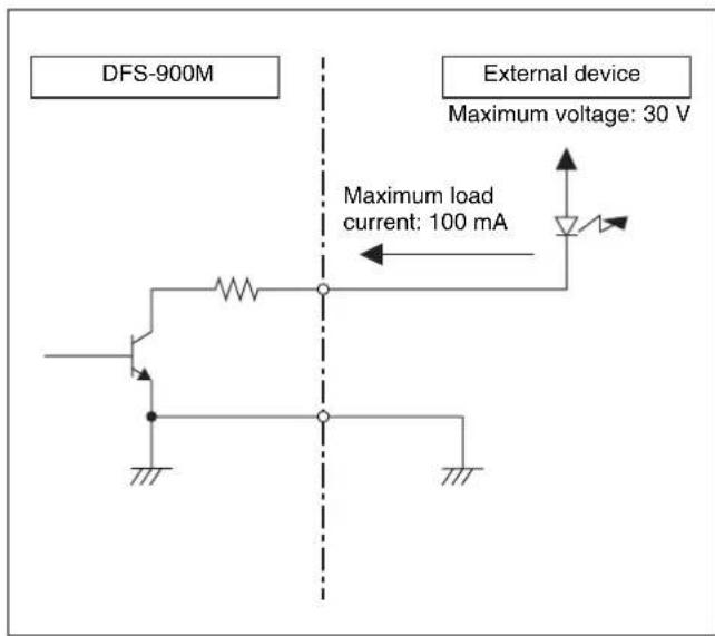

External Dimensions
BKDF-901 1M/E Control Panel
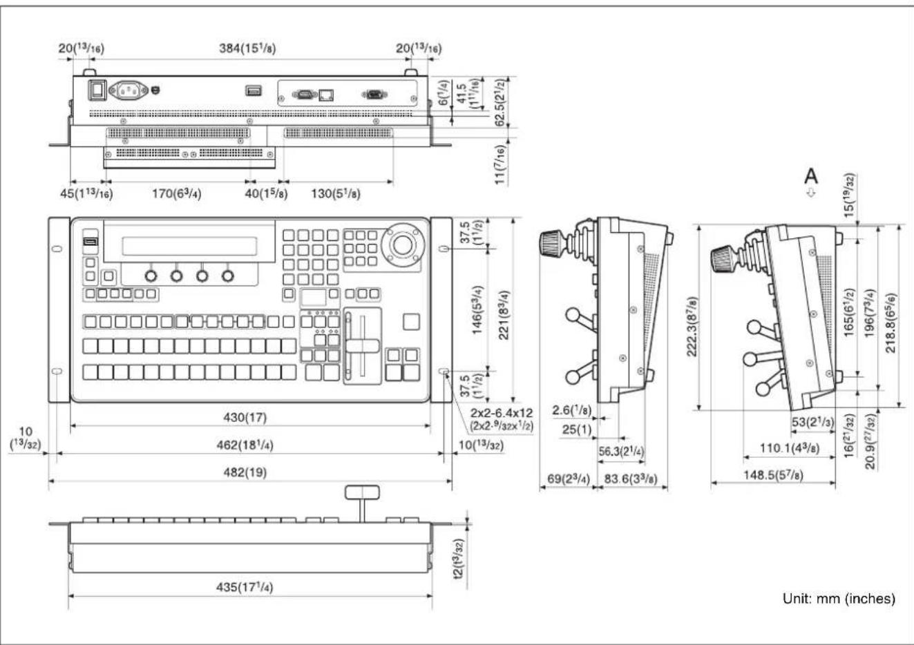

Unit: mm (inches)


Unit: mm (inches)
Glossary
AUX output
A signal output from an AUX (auxiliary) connector to an external device.
Background transition
A transition that switches away from the background video of the current program output to other video.
Color matte
An internally generated color signal. You can adjust the hue (Hue), saturation (Sat), and luminance (Lum) of color mattes.
DME (digital multi effects)
A special effect (3D, lighting, etc.) created with digital video processing.
DME wipe
A wipe that uses a DME effect to switch between video signals.
Downstream key (DSK)
A function which allows video to be composed by taking video to which an effect has already been applied and adding further images and text. It is called downstream key because this processing is done as the last stage in the flow of video processing.
Event
A set of control panel settings registered as data. You can register video selections and effect settings as events, and then automatically restore the same state by recalling the event.
Fade to black
An effect in which video fades out to a black screen.
Key
An effect in which part of the video is cut out and replaced by an image, text, or other content.
Key transition
A transition in which a key is inserted into or deleted from the program video.
Mix
A type of transition effect. Another video signal is mixed into the current video signal, gradually replacing it.
Preset bus
A bus for the video signal that will become the program video after a background transition. This video is selected and output before execution of the transition.
Preview output
Output that allows you to check the program video that will appear after a transition, before actual execution of the transition.
Program bus
A bus for the output of program output signals.
Program output
The final video signal output from this system after applying effects. The video seen by viewers.
Sequence
A set of control panel settings stored as motion video. The settings for a single instant are stored as a single frame of the video. The sequence is played by recalling the frames in turn, with the video changing smoothly between the current frame and the next frame.
Still image memory
Internal memory for storing image data as files.
Transition
Switching from one video signal to a different video signal over a certain time interval. Transitions can be used to compose or erasing graphics or text using functions such as downstream keys or Picture-in-Picture.
Wipe
A type of transition effect. A new video signal replaces the current video signal by gradually wiping it away.
Index
Numerics
32-bit TGA 120
3D effects 140
3D mode 172
operation 175
4:3BGS 83
A
AC power cord 57
Analog video signal Input setting 83
Output setting 92
Ancillary data 89
Assign
AUX output 89
Assigning
PROGRAM and PRESET
selection button 76
B
Background
selecting 108
switching 109
Backup 167
Basic operations 108
Baud rate 162
BKDF-901 13
BKDF-902 21
BKDF-910 31
Up converter setting 81
BKDF-911 31
Input signal setting 83
Up converter setting 81
BKDF-912 31
Input signal setting 85
BKDF-940
installation position 46
BKDF-950
installation position 46
setting 96
BKDF-960 31
Down converter setting 91
BKDF-961 31
Down converter setting 91
Output signal setting 92
BKDF-962 32
Output signal setting 94
BKDF-990 32
installing/removing 51
POWER switch and indicator 28
Boot mode 59
Border
adjusting color 138
beveled edge 139
DME wipe pattern 137
highlight 139
inner width 138
outer width 138
softness 139
wipe pattern 132
Box mask 150
Box Mask sub menu 150
C
Capture 119
Channel number 39
Input expansion board 40
Output expansion board 41
Chroma key 123
Color matte 117
background transition 118
changing 117
Communication protocol 162
Connection
mouse 65
PC monitor 65
peripheral device 33
switcher system 54
touch panel monitor 65
Control panel 13, 21
connecting 57
external connection block 14, 22
operating blocks 13, 21
power block 14,22
rear panel 19,26
Coordinates 134
Cross-point bus block 15
Cross-point selection buttons
assigning signals 76
Cut 109
downstream key 129
key 126
D
Data
backup 167
clearing 167
recalling 167
Defocus 145
dfs900.ini 75
adjusting display position/display size 99
DFS-900M 28
Dimensions 215
Display panel 19, 26, 60, 64
Display panel/menu control block 26
Displaying
menu 63
DME
adjusting position 136
aspect ratio 136
border 137
crop 137
customizing 134
defocus 145
enable/disable 137
key 129
lens 143
lighting effects 146
mirror 145
mosaic 142
page peel 144
page turn 143
registering user pattern 147
ripple 141
rotation angle 136
setup 137
slats 142
splits 144
swirl 142
warp effects 140
DME Basic sub menu 134
DME menu
reset 134
restoring the default values 134
DME/SETUP block 18, 25
Downstream key 129, 130
box mask 150
DSK preview function 103
DSK/fade to black control block 24
DSK/fade to black control block 24
DVI boards 209, 210
DVI signal
Input setting 85
Output setting 94
E
Edge
key 148
Edge Shadow sub menu 148
Event
deleting 155
recalling event 152
register 151
Expansion board installation tray 39
External control 161
External device interface connector 29
F
Fade to black 131
DSK/fade to black control block 24

Features 11
Frame synchronizer 79
capturing still image 80
Function expansion board
installing/removing 46
G
Global coordinates
enable/disable 137
GPI input 163
GPI output 166
GUI menu
connecting devices for display and operation 65
GUI menu screen
basic operations 69
configuration 68
H
HD/SD-SDI boards 208, 209
Heat transfer sheet
BKDF-940 48
I/O expansion board 43
|
I/O expansion board
installing/removing 39
I/O expansion board slot 39
I/O expansion slot 28
Input board 31
Input signal
adjusting level 87
capturing still image 80
changing signal display name 74
inputting up-convert 81
setting 74
Interface 161
J
Joystick block 16, 26
K
Key 122
adjusting 132
changing priorities 128
chroma key 123
composing video 122
cut 126
DME 129
downstream key 129, 130
edge 148
KEY DELEGATION block 15
Key/AUX bus control block 22
KEYER block 22
mask 147
mix 127
setting up 122
type 122
wipe 127
KEY DELEGATION block 15
Key delegation block 15
Key Mask sub menu 147
Key/AUX bus control block 22
KEYER block 14,22
Keyer menu 63
Keyframe
adding 159
deleting 160
L
Lens 143
Light 1 146
Light 2 146
Light source
position/size/color 146
type 146
Light sub menu 146
Lighting effects 146
M
M/E cross-point bus block 23
M/E transition block 25
Mask
key 147
Memory for the storage of still image
118
acquiring still image files 118
capturing 119
downloading still image 118
Menu 63
basic configuration 63
display panel 19
display panel/menu control block 26
displaying 63
GUI menu screens 64
menu control block 19
operating 64
Menu control block 19, 26
Menu structure 176
Messages 197
Mirror 145
Mix 113
downstream key 130
key 127
Modify
wipe pattern 133
Mosaic 142
Multi-view output
adding frame 101
adjusting display position/display size 99
child window number 99
setting 96
window partition type 99
N
Names and functions of parts 13
Numeric keypad 17, 26
0
Optional accessories 208
Options 31, 39
BKDF-901 13
BKDF-902 21
BKDF-910 31,39
BKDF-911 31
BKDF-912 31
BKDF-940 39
BKDF-950 39
BKDF-960 39
BKDF-961 31
BKDF-962 32
BKDF-990 32,39
I/O expansion slot 28
input board 31
installing 39
output board 31
POWER switch and indicator 28
Output Board 31
Output signal 89
assigning to AUX output 89
down-convert output 91
P
Page Peel 144
Page Turn 143
Parity bit 162
Pin assignments 211
Power
off 60
on 58
Power block 14, 22
control panel 14, 22
Power connectors 30
Power supply unit 32
installing/removing 51
POWER switch
control panel 59
processor unit 59
POWER switch and indicator 28 power supply unit 32
POWER switches (A and B) 26
PRESET selection button 15
Processor unit 28
connecting 57
front panel 28
power connectors 30
POWER switch and indicator 28 rear panel 28
PROGRAM selection button 15
PROGRAM/PRESET cross-point bus block 23
PROGRAM/PRESET transition block 24
R
Reference sync signal setting 73
Register
event 151
operation/setting 151
user pattern 133, 147
Ripple 141
S
SD boards 209, 210
Sequence
creating 156
deleting 160
editing 159
playing 158
recalling 156
Sequence/Event menu 63
Serial interface 161
Settings 71
Analog video signal 83, 92
BKDF-950 96
cross-point bus block 105
down-converter 91
DSK preview function 103
DVI signal 85, 94
frame synchronizer 79
input signal 74
internal clock 106
M/E cross-point bus block 23
output signal 89
PROGRAM/PRESET cross-point bus block 23
reference sync signal 73
timing of video switching 104
up-converter 81
video format 71
Setup menu 63
SHUTDOWN button 61
Shutdown processing 61
Signal display name changing 74
usable characters 76
Slats 142
Source coordinates 134
Specifications 207
Splits 144
Standard I/O module 29,46
DME1, DME2 sockets 46
MV1, MV2 sockets 46
Still image
32-bit TGA 120
acquiring still image files 118
background transition 120
capturing 80, 119
deleting 121
downloading 118
writing to USB flash drive 121
Still Store menu 63
Sub menu 63
displaying 64
Swirl 142
System 169
T
Tally output 164
Target coordinates 134
Touch panel monitor
calibration 66
connecting 65
Transition 109
cut 109
M/E transition block 25
mix 113
PROGRAM/PRESET transition
block 24
transition block 15
wipe 115
Transition block 15
Transition menu 63
Transition rate 117
Troubleshooting 205
Type 146
U
Up-converter 81
Update 169
Updating software 202
USB flash drive 75
recalling all event data 154
recalling event in page unit 154
saving event data 152
writing still image 121
USB MEMORY connector 75
User patterns
registering 133, 147
User sub menu 133, 147
V
Video format 71
when an SD format is selected 72
W
Warp effects 140
Warp sub menu 140
Wipe 115
adjusting 132
customizing wipe pattern 132
key 127
Wipe Border Color sub menu 132
Wipe Modify sub menu 133
Wipe pattern
adjusting position 133
aspect ratio 133
border 132
customizing 132
modifying 133
registering user pattern 133
rotation angle 133
Wipe Pattern sub menu 132

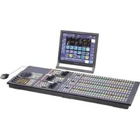

- Multi Format Switcher
- Owner's Record
- WARNING
- To reduce the risk of fire or electric shock, do not expose this apparatus to rain or moisture.
- To avoid electrical shock, do not open the cabinet. Refer servicing to qualified personnel only.
- THIS APPARATUS MUST BE EARTHED.
- For the customers in the U.S.A.
- For the customers in Canada
- WARNING: THIS WARNING IS APPLICABLE FOR USA ONLY.
- WARNING: THIS WARNING IS APPLICABLE FOR OTHER COUNTRIES.
- IMPORTANT (for BKDF-901/902)
- For the customers in Europe
- For the customers in Europe, Australia and New Zealand
- For kundene i Norge
- For DFS-900M
- Attention-when the product is installed in Rack:
- For BKDF-901/902
- AVERTISSEMENT
- Features of This System ....11
- Chapter 2 Names and Functions of Parts
- BKDF-901 1M/E Control Panel....13
- BKDF-902 1.5M/E Control Panel....21
- DFS-900M Processor Unit....28
- Options 31
- Chapter 3 Preparations
- Connecting Peripheral Devices....33
- Installing Optional Expansion Boards....39
- Connecting Up the Switcher....54
- Menu Operations 63
- Basic Switcher Settings....71
- Chapter 4 Basic Operations
- Selecting Backgrounds....108
- Switching Backgrounds....109
- Using Color Mattes....117
- Using Internally Stored Still Images ....118
- Using Keys to Compose Video....122
- Using Fade to Black ....131
- Chapter 5 Adjusting Wipes and Keys
- Customizing Wipe Patterns ....132
- Customizing DME Effects ....134
- Chapter 6 Registering Operations and Settings
- Chapter 7 External Control Interface Settings
- Chapter 8 Other Operations and Settings
- Chapter 9 3D Mode
- Appendix
- Features of This System
- Multi-format support
- Extensible inputs and outputs
- Advanced special effects
- Multi-view function
- Simple operations in GUI menu screens
- Compact and easy-to-use control panels
- Functions Newly Supported in Version 2.0
- Functions Newly Supported in Version 2.1
- Names and Functions of Parts
- 2
- BKDF-901 1M/E Control Panel
- BKDF-901 Operating Blocks
- External Connections and Power Block
- ①USB MEMORY connector (Type-A)
- Note
- ② EDITOR button
- ③GPI button
- ④SHUTDOWN (start shutdown process) button
- KEYER Block
- ①Key type selection buttons
- ②MASK button
- ③EDGE SHADOW button
- ④DME ENABLE (enable/disable digital multi effects) button
- KEY DELEGATION Block
- Cross-Point Bus Block
- ①PROGRAM selection button row
- ②PRESET selection button row
- About the SHIFT buttons
- Transition Block
- ①TRANS PVW (transition preview) button
- Notes
- ②Next transition selection buttons
- ③ Transition type selection buttons
- ④ Transition execution block
- ⑤DSK (downstream key) transition buttons
- ⑥FTB (fade to black) button
- ⑦ Transition range and direction buttons
- ⑧Key priorities block
- Joystick Block
- ①DEFAULT button
- ② AUTO CK (auto chroma key) button
- ③DME POS (DME image position) button
- ④FINE (fine adjustment) button
- ⑤DME ROT (DME rotation angle) button
- ⑥ WIPE POS (wipe center position) button
- ⑦X, Y, Z (parameter selection) buttons
- ⑧Joystick
- Numeric Keypad
- Buttons used when the EVENT button is lit (event mode)
- Buttons used when the SEQ button is lit (sequence mode)
- DME/SETUP Block
- ①DME setting buttons
- ② Setup buttons
- ③ USER/ STILL button
- ④SHIFT button
- Display Panel/Menu Control Block
- ①Display panel
- ②F1 to F4 knobs
- BKDF-901 Rear Panel
- ①EXT DISPLAY (external display) connector (high-density D-sub 15-pin)
- ②PROCESSOR connector (RJ-45)
- CAUTION
- ATTENTION
- ④DEVICE connector (USB Type-A)
- ⑤ Ground terminal
- ⑥\~ AC IN connector
- ⑦ POWER switch
- BKDF-902 1.5M/E Control Panel
- BKDF-902 Operating Blocks
- Key/AUX (Auxiliary) Bus Control Block
- ①Key delegation buttons
- ② AUX (Auxiliary) delegation buttons
- ③KEY/AUX (auxiliary) bus selection buttons
- ④ Output selection buttons
- MV1 (multi-view 1)/K OUT (key output) button:
- ⑤SHIFT button
- M/E Cross-Point Bus Block
- ①M/E bus A selection button row
- ②M/E bus B selection button row
- PROGRAM/PRESET Cross-Point Bus Block
- ①PROGRAM bus selection button row
- ②PRESET bus selection button row
- ③M/E buttons
- PROGRAM/PRESET Transition Block
- ① Transition type selection buttons
- ② Transition range and direction buttons
- ③ Transition execution block
- DSK (Downstream Key)/Fade to Black Control Block
- M/E Transition Block
- ①Next transition selection buttons
- ② Transition type selection buttons
- ③ Transition range and direction buttons
- ④Key priorities block
- ⑤ Transition execution block
- DME/SETUP Block
- ②USER button
- ③ Setup buttons
- ④ STILL button
- Joystick Block
- Numeric Keypad
- Display Panel/Menu Control Block
- BKDF-902 Rear Panel
- DFS-900M Processor Unit
- Front Panel
- POWER switch and indicator
- Rear Panel
- I/O expansion slots
- ①I/O expansion slot (upper)
- ②I/O expansion slot (lower)
- Standard I/O module
- ①SDI IN (SDI input) 1 to 8 connectors (BNC type)
- ②SDI OUT (SDI output) connectors (BNC type)
- External device interface connectors
- ① REF IN (reference sync signal input) connectors (BNC type)
- ②REF OUT (reference sync signal output) connectors (BNC type)
- ③ REMOTE 1, 2, 3 connectors (D-sub 9-pin)
- ④ EDITOR connector (D-sub 9-pin)
- ⑤ PANEL connector (RJ-45)
- ⑦ TALLY/GPI OUT (tally/GPI output) connector (D-sub 37-pin)
- ①\~ AC IN (AC power input) connector A
- ②\~ AC IN connector B
- ③ Ground terminal
- Options
- BKDF-910 4 SDI Input Board
- SDI IN (SDI input) 1 to 4 connectors (BNC type)
- BKDF-911 2 SD Video Input Board
- ANALOG IN (analog input) 1 to 4 connectors (BNC type)
- BKDF-912 2 DVI Input Board
- DVI IN (DVI input) 1 and 2 connectors (DVI-I type)
- BKDF-960 4 SDI Output Board
- SDI OUT (SDI output) 1 to 4 connectors (BNC type)
- BKDF-961 2 SD Video Output Board
- ANALOG OUT (analog output) 1 to 4 connectors (BNC type)
- BKDF-962 2 DVI Output Board
- DVI OUT (DVI output) 1 and 2 connectors (DVI-I type)
- BKDF-990 Power Supply Unit
- Power switch B
- Other Options
- Connecting Peripheral Devices
- Connection Example 1: Live Recording / Playout System
- Connection Example 2: System with Editor Connected
- Connection Example 3: Connection to a Device Equipped with a DVI (DVI-I) Connector
- Installing Optional Expansion Boards
- Installing I/O Expansion Boards
- About installation locations and channel numbers
- Output expansion board channel numbers
- To install I/O expansion boards
- To remove I/O expansion boards
- Installing Function Expansion Boards
- About installation locations
- To install function expansion boards
- To remove function expansion boards
- Installing the BKDF-990 Power Supply Unit
- To remove the BKDF-990
- Connecting Up the Switcher
- Changing the Internal Switch Setting in the Processor Unit (When Using the BKDF-902)
- Connecting the Processor Unit and the Control Panel
- Powering the System On
- Tip
- To power off
- Press the SHUTDOWN button.
- Press the F2 knob.
- Menu Operations
- Basic Menu Configuration
- Displaying Menus
- Operating in Menus
- Adjustment knob operations
- Menu Operations in the GUI Menus
- Connecting devices needed for display and operation
- Connecting a PC monitor and USB mouse
- Connecting a touch panel monitor
- To calibrate a touch panel monitor
- GUI menu screen configuration
- ①Menu category section
- ②Sub menu section
- ③Status section
- ④Parameter section
- Basic operations in the GUI menu screens
- To select menu and sub menu items
- Basic Switcher Settings
- Setting the Video Format
- Hold the F1 knob down for one second or longer.
- Press the F2 knob.
- Rotate the F4 knob to set the system delay.
- Restart the switcher.
- Settings when an SD format (525/59 or 625/50) is selected
- F2 knob (SET) setting
- F3 knob (SD ASPECT) setting
- Making Input and Output Reference Sync Signal Settings
- Make the reference sync signal settings.
- Making Settings Related to Input Signals
- Changing signal display names
- Assigning video input signals to cross-point selection buttons
- When using the BKDF-901
- When using the BKDF-902
- Using the internal frame synchronizers
- To enable frame synchronizers
- When using the BKDF-901: Press the PRESET selection button that selects the input you want to set.
- Enable frame synchronizer memory by rotating the F2 knob to select "On".
- Rotate the F3 knob and select "Live".
- Repeat steps 4 to 6 as required to set other inputs.
- To capture still images from input signals
- Making up-convert input settings
- Specifying the signal type of analog input signals
- Specifying the signal type of DVI input signals
- Adjusting input signals
- Making Settings Related to Output Signals
- Selecting output signals for AUX output
- Tips
- When using the BKDF-901: Press the AUX button.
- Making down-convert output settings
- Specifying the signal type of analog output signals
- Specifying the signal type of DVI output signals
- Making multi-view output settings
- To specify the partition type and assign output video to child windows
- Multi-view window partition types and child window numbers
- To adjust the display positions and sizes of child window titles
- Title display positions and parameter values
- To add frames to child windows
- Enabling the DSK preview function
- Making Other Settings
- Specifying the timing of video switching
- Selecting the operating mode of the SHIFT buttons
- Setting the Date and Time
- Basic Operations
- Chapter
- 4
- Selecting Backgrounds
- To select a background
- To select the background that appears after a transition
- Switching Backgrounds
- Cutting to a New Background
- Basic cut operations
- Cutting directly with the cross-point selection buttons
- Cutting with the CUT button after checking the next video in the preview screen
- Press the CUT button.
- Cutting by using GPI output
- Using Transitions to Switch to the Next Video (Mix and Wipe)
- Basic transition effect operations
- How to execute transitions
- Buttons and controls used to execute transitions
- Using the AUTO TRANS buttons
- Using the fader lever
- Reversing the directions of transitions
- Using the REVERSE button (when using the BKDF-901) or the REV button (when using the BKDF-902)
- Using the NORM/REV button
- Limiting the effective range of the fader lever
- Limiting the range by using a menu
- Limiting the range to the desired position
- Switching with Mix Transitions
- - MIX transition
- • FAM (full additive mix) transition
- • NAM (non-additive mix) transition
- Basic mix operations
- Switching with Wipe and DME Wipe Transitions
- Basic wipe and DME wipe operations
- WIPE menu
- DME menu
- M/E WIPE menu
- P/P WIPE menu
- Setting Transition Rates
- Using Color Mattes
- Assigning Color Mattes to Cross-Point Selection Buttons
- Using Color Mattes in Background Transitions
- Using Internally Stored Still Images
- Acquiring Still Image Files
- Downloading still images from USB flash drives
- Downloading captured still images to still image memory
- Using Stored Still Images in Background Transitions
- Using 32-bit TGA Still Image Files in Keys
- Writing Still Images to USB Flash Drives
- Deleting Still Image Files
- Using Keys to Compose Video
- Key types
- Setting Up Keys
- External (EXT) key parameters (External Key menu)
- Self (SELF) key parameters (Self Key menu)
- Setting up chroma keys
- To create an auto chroma key
- To adjust an auto chroma key
- To adjust key opacity
- To set the chroma key cursor
- Changing Key Priorities
- Inserting Downstream Keys (with a Mix)
- Using Fade to Black
- Adjusting Wipes and Keys
- 5
- Customizing Wipe Patterns
- Adding Borders to Wipe Patterns
- To display the Wipe Pattern (Pattern) and Wipe Border Color (Border Color) sub menus
- Wipe Pattern (Pattern) sub menu parameters
- Wipe Border Color (Border Color) sub menu parameters
- Modifying Wipe Patterns
- To display the Wipe Modify (Modify) sub menu
- Wipe Modify (Modify) sub menu parameters
- Registering User Patterns
- To unregister a pattern
- Customizing DME Effects
- To restore the default values for all settings in a sub menu of the DME menu (reset)
- Changing the Position, Shape, and Size of Images
- To display the DME Basic sub menus
- Position sub menu and Rotation sub menu parameters
- Position sub menu parameters
- Rotation sub menu parameters
- Aspect sub menu parameters
- Crop sub menu parameters
- Setup sub menu parameters
- Adding Borders to Images
- To display Border sub menus
- Border Color sub menu parameters
- Inner Width sub menu parameters
- Outer Width sub menu parameters
- Softness sub menu parameters
- Bevel Color sub menu parameters
- Border HL (Highlight Setup) sub menu parameters
- Adding Trail Effects, and Changing the Color Type
- To display the Sub Effects sub menus
- Trail sub menu parameters
- Chroma Control sub menu parameters
- Adjusting 3D DME Warp Effects
- To display the WARP sub menus
- Ripple sub menu parameters
- Mosaic sub menu parameters
- Slats sub menu parameters
- Lens sub menu parameters
- Page Peel sub menu parameters
- Splits sub menu parameters
- Mirror sub menu parameters
- Defocus sub menu parameters
- Adding Lighting Effects
- To display the Light sub menus
- To select the type of light source in the Type sub menu
- Light 1 and Light 2 sub menu parameters
- xxx L1/xxx L2 Position (Position)
- Lxxx L1/xxx L2 Color (Color)
- Applying Masks to Keys
- To select a mask pattern and change the position or size of the pattern
- Adding Edges to Keys
- Edge Shadow sub menu parameters
- Masking Downstream Keys with Box Masks
- To adjust the position of the box mask
- Registering Operations and Settings
- Event Operations
- Registering Events
- To save all event data to a USB flash drive
- Recalling Events
- To recall an event while specifying certain types of settings
- To recall all event data from a USB flash drive
- To recall events in page units from the USB flash drives
- Deleting Events
- To delete events in page units
- To recall events from an editor
- Sequence Operations
- Creating Sequences
- Recalling Sequences
- To display the video of the first keyframe when a sequence is recalled
- To replace the current video settings with the settings of a registered sequence
- Playing Sequences
- Editing Sequences
- To change parameters
- To display the Seq Edit sub menu
- To add keyframes
- To delete keyframes
- Deleting Sequences
- External Control Interface Settings
- Serial Interface Settings
- Communications Protocol Settings
- Baud Rate Settings
- Parity Bit Settings
- GPI Input Settings
- To change GPI input settings
- To display the GPI sub menu
- To change settings
- Tally Output Settings
- To change tally output settings
- To display the Tally sub menu
- GPI Output Settings
- To set the GPI output
- Other Operations and Settings
- 8
- Backing Up Data
- Backing Up, Restoring, and Clearing All Data
- To back up all data to a USB flash drive
- To recall all data from a USB flash drive
- To clear all data from the memory of the control panel
- Backing Up, Restoring, and Clearing System Data
- To back up system data to a USB flash drive
- To recall system data from a USB flash drive
- To clear system data from a USB flash drive
- Backing Up, Restoring, and Clearing File Data
- To back up file data to a USB flash drive
- Updating the System
- To update the system
- To display or hide the GUI menu cursor
- To update the software from the Update sub menu
- Status Information
- To display the Status sub menus
- Option Board Information
- Software Version Information
- Alarms
- Overview
- I/O of 3D Mode Signals
- Input example
- 3D signal input destinations
- 2D signal input destinations
- Signal output and connection destinations
- 3D Mode Signal Assignments
- System Settings
- Switching to 3D Mode
- Selecting the 2D/3D Mode of Stored Still Images
- Signal Assignments for Using Still Images in 3D Mode
- 3D Mode Operations
- Menu Structure
- Still Store Menu (for Still Image Settings)
- Sequence Event Menu (for Sequence and Event Registration)
- DME Menu (for DME Settings)
- Pattern List
- Wipe
- DME Wipe
- Messages and Actions to Take
- Updating the Software
- Checking the Software Versions
- Preparing for Software Update
- Preparing equipment and the most recent versions of software
- Preparing a USB flash drive for software update
- Backing up all data
- Preparatory operations
- To update control panel software (GUI)
- To update the firmware
- Upon completion of version update
- Performing Update Confirmation, Data Clear, and Data Restoration
- To check for correct version update
- To clear (initialize) all data
- To restore all data
- Troubleshooting
- Problems on Functions
- Specifications
- Signal processing
- Inputs/outputs
- Interfaces
- General
- Interface
- Operating panel
- Optional Products
- BKDF-940 2 CH DME Board
- BKDF-950 Multi Viewer Board
- RMM-10 Rack Mount Kit
- Pin Assignments
- REMOTE (1 to 3) connector (D-sub 9-pin, female)
- EDITOR connector (D-sub 9-pin, female)
- BKDF-901/902 control panel
- MAINTENANCE connector (D-sub 9-pin, male)
- DVI IN connector (DVI-I 29-pin)
- DVI OUT connector (DVI-I 29-pin)
- Example Connection of GPI Input
- Example Connection of Tally/GPI Output
- External Dimensions
- Glossary
- AUX output
- Background transition
- Color matte
- DME (digital multi effects)
- Downstream key (DSK)
- Event
- Fade to black
- Key
- Key transition
- Mix
- Preset bus
- Preview output
- Program bus
- Program output
- Sequence
- Still image memory
- Transition
- Index
- Numerics
- A
- B
- C
- D
- E
- F
- G
- H
- |
- J
- K
- L
- M
- N
- 0
- P
- R
- S
- T
- U
- V
- W
Brand : SONY
Model : DFS-900M
Category : Video switch