
ICP-3016 - Video switch SONY - Free user manual and instructions
Find the device manual for free ICP-3016 SONY in PDF.


| Product Type | Cordless Telephone |
| Brand | Sony |
| Model | ICP-3016 |
| Dimensions (Handset) | 180 x 50 x 30 mm |
| Weight (Handset) | 150 g |
| Power Supply | 2 x AAA Ni-MH rechargeable batteries |
| Display | Backlit LCD display |
| Keypad | 12-digit dialing keys, speakerphone button |
| Ringer Type | Polyphonic ringer (selectable melodies) |
| Ringer Volume | Adjustable (low/medium/high/off) |
| Range | Up to 300 m outdoors, 50 m indoors |
| Frequency Band | DECT 1.9 GHz |
| Battery Life (Standby) | Up to 100 hours |
| Battery Life (Talk Time) | Up to 10 hours |
| Number of Handsets Supported | Up to 6 (expandable) |
| Intercom Function | Yes, between handsets |
| Caller ID | Yes (requires network service) |
| Phonebook | Up to 100 contacts |
| Hands-Free Speakerphone | Yes (on handset) |
| Cleaning | Wipe with a soft, dry cloth; avoid solvents |
| Maintenance | Keep dry; replace batteries when necessary |
| Safety | Do not expose to moisture or extreme temperatures |
| Spare Parts | Batteries, chargers, handset housings available |
| Repairability | Modular design; batteries user-replaceable |
Frequently Asked Questions - ICP-3016 SONY
User questions about ICP-3016 SONY
0 question about this device. Answer the ones you know or ask your own.
Ask a new question about this device
Download the instructions for your Video switch in PDF format for free! Find your manual ICP-3016 - SONY and take your electronic device back in hand. On this page are published all the documents necessary for the use of your device. ICP-3016 by SONY.
USER MANUAL ICP-3016 SONY
Multi Format Switcher System
MVS-6520 System MVS-6530 System MVS-3000A System MVS-3000 System
(With ICP-series Control Panel)
MVS-6520 MVS-6530 MVS-3000A MVS-3000 ICP-6520 ICP-6530 ICP-3000 ICP-3016 ICP-6511 MKS-6550 MKS-6570
Startup Guide English
Software Version 1.10 and Later 1st Edition (Revised 2)
MVS-6520 System MVS-6530 System MVS-3000A System MVS-3000 System (SY) 4-448-161-13 (1)
Sony Corporation
Printed in Japan 2019.04 32 © 2012

NOTICE TO USERS
© 2012, 2013 Sony Corporation. All rights reserved. This manual or the software described herein, in whole or in part, may not be reproduced, translated or reduced to any machine readable form without prior written approval from Sony Corporation.
SONY CORPORATION PROVIDES NO WARRANTY WITH REGARD TO THIS MANUAL, THE SOFTWARE OR OTHER INFORMATION CONTAINED HEREIN AND HEREBY EXPRESSLY DISCLAIMS ANY IMPLIED WARRANTIES OF MERCHANTABILITY OR FITNESS FOR ANY PARTICULAR PURPOSE WITH REGARD TO THIS MANUAL, THE SOFTWARE OR SUCH OTHER INFORMATION. IN NO EVENT SHALL SONY CORPORATION BE LIABLE FOR ANY INCIDENTAL, CONSEQUENTIAL OR SPECIAL DAMAGES, WHETHER BASED ON TORT, CONTRACT, OR OTHERWISE, ARISING OUT OF OR IN CONNECTION WITH THIS MANUAL, THE SOFTWARE OR OTHER INFORMATION CONTAINED HEREIN OR THE USE THEREOF.
Sony Corporation reserves the right to make any modification to this manual or the information contained herein at any time without notice. The software described herein may also be governed by the terms of a separate user license agreement.
Table of Contents
Overview
Introduction 4
Names of Parts.... 5
MVS-6520/6530/3000A/3000 Multi Format Switcher Processor..... 5
ICP-6520/6530/3000/3016 Control Panel..... 8
ICP-6511 Menu Panel....9
Connection
System Configuration.... 10
Video Input/Output Systems.... 10
Device Control Systems.... 11
Connecting Devices.... 12
MVS System Connection.... 12
Peripheral Device Connection 13
Preparation
Preparation Procedure 15
Turning Power On/Off.... 16
Opening Menus.... 18
Configuring the Network 19
Setting the Control Panel Type.... 20
Setting Signal Formats.... 21
Setting the Signal Format.... 21
Setting the Screen Aspect Ratio.... 22
Assigning Signals to Cross-Point Buttons 22
Setting the Signal Name.... 22
Assigning Pair Signals to Cross-Point Buttons.... 23
Assigning M/E Reentry Input Signals to Cross-Point Buttons.... 24
Assigning Output Signals 24
Setting Monitor Outputs 24
Using Multi Viewer 25
Setting Multi Viewer Output.... 25
Configuring Multi Viewer 26
Assigning Signals to Subscreens...... 26
Setting Multi Viewer Tally Output ...... 27
Setting Tally.... 28
Setting Parallel Tally.... 28
Setting Serial Tally.... 28
Assigning 8-Keyer Buttons (MVS-6530 only) 37
Assigning Key 5 to Key 8 to 1st Row Buttons....37
Assigning Key Selection Functions to Next Transition Selection Buttons..... 38
Enabling Background DME Wipes (MVS-3000/3000A only).... 39
Setting the Startup State 39
Selecting the Startup Mode at Power On .... 39
Customizing the User Default Settings..... 40
Saving Data to Removable Disk .... 41
Setting Up a Removable Disk for Use ..... 41
Saving/Recalling User Settings on Removable Disks.... 42
Setting Simple Connection of AUX Bus Remote Panel 43
Basic Image Creation Operations
Video Switching (Transitions) 45
Types of Transitions (Mix/NAM/Wipe/DME Wipe) ..... 45
Names of Parts in the Control Panel ...... 46
Video Transitions using Cuts...... 47
Video Transitions using Wipes or Mixes.... 48
Saving DME Wipe Settings in a DME Wipe Snapshot .... 50
Setting Picture-in-Picture (DME Wipe)..... 50
Saving/Recalling a DME Wipe Snapshot ... 52
Inserting Titles (Keys) 53
What is a Key? 53
Entering Titles using Luminance Keys...... 53
Composing Images using Chroma Keys 56
Overview
Introduction
The Startup Guide (this document) describes the basic settings and operations to begin using the MVS-6520/6530/3000A/3000 system.
For details about settings and operations, refer to the User's Guide.
System name and nomenclature
An MVS system using the MVS-6520, MVS-6530, or MVS-3000A Multi Format Switcher Processor is referred to as the “MVS-6520/6530/3000A system,” and an MVS system using the MVS-3000 Multi Format Switcher Processor is referred to as the “MVS-3000 system.”
In this document, the MVS-6520/6530/3000A system and MVS-3000 system are collectively referred to as the “MVS system.”
Also, the ICP-6520, ICP-6530, ICP-3000, and ICP-3016 control panels are collectively referred to as the “ICP-series control panel.”
Illustrations and screenshots
The illustrations and screenshots used in this document to describe functions and procedures may vary depending on the system configuration.
Names of Parts
MVS-6520/6530/3000A/3000 Multi Format Switcher Processor
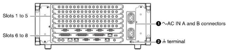
Rear panel: MVS-6520, MVS-3000A, and MVS-3000

Slots 1 to 5

Slots 6 to 8


Rear panel: MVS-6530

Slots 1 to 5
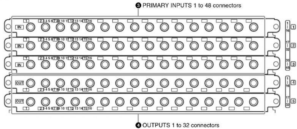
Slots 6 to 8

①~AC IN (AC power input) A and B connectors (3-pin)
Connect to 100 V to 240 V AC power supply with the optional AC power cords.
The unit is equipped with two power supplies. When A or B power supply is connected, unit operation can proceed.
② (signal ground) terminal
Connect to the system ground.
③PRIMARY INPUTS
1 to 32 connectors (BNC-type) ^1) : MVS-6520/3000A/3000
1 to 48 connectors (BNC-type) ^1) : MVS-6530
These connectors allow you to input up to 32 or up to 48 serial digital video signals to the MVS-6520/3000A/3000 or MVS-6530, respectively.
④ OUTPUTS
1 to 16 connectors (BNC-type) ^1) : MVS-6520/
3000A/3000
1 to 32 connectors (BNC-type) ^1) : MVS-6530
These connectors output serial digital signals. You can assign them as program output, preview output, AUX output, and so on.
Make output assignments on the MVS system control panel.
The configurable connectors for each signal type are given below.
| Switcher processor | Type of output signal | ||
| Re-Entry Source | Aux Bus Output/MV/FC/DME | ||
| MVS-6520/3000A | OUTPUTS 1 to 16 | OUTPUTS 1 to 16 | OUTPUTS 1 to 16 (FC: 15, 16 combination only) |
| MVS-6530 | OUTPUTS 1 to 24 | OUTPUTS 1 to 24 | OUTPUTS 1 to 32 (FC: 15, 16 and 31, 32 combinations only) |
| MVS-3000 | OUTPUTS 1 to 12 | OUTPUTS 1 to 12 | OUTPUTS 1 to 16 (FC: 15, 16 combination only) |
For details about output signals and settings, refer to the User's Guide.
⑤ TALLY/GPI IN (tally/general purpose interface input) 1 to 18 and TALLY/GPI OUT (tally/general purpose interface output) 1 to 48 connectors (D-sub 25-pin)
Output tally data created with the control panel of the MVS system (open collector). These connectors can also be used as GPI output ports.
You can also input trigger signals as GPI inputs.
Input and output settings are made on the control panel of the MVS system.
⑥ SERIAL TALLY connector (D-sub 9-pin, RS-422A)
Output tally data created with the control panel of the MVS system.
⑦ REMOTE 1 to 4 connectors (D-sub 9-pin, RS-422A)
Connect devices supporting Sony 9-pin VTR, VDCP (Video Disk Communications Protocol), or P-Bus (Peripheral II Protocol) protocols.
⑧ UTIL (FM) (utility (frame memory data)) connector (RJ-45 compliant)
Intended for future expansion.
⑨FM (frame memory) DEVICE connector (USB 2.0 compliant)
This connector is for attaching an external HDD for frame memory. ^2)
⑩S-BUS connector (BNC-type) 1)
Connect this connector with a BNC cable to an S-Bus data link via a T bridge.
Connecting devices such as IXS series routing switchers and MKS-8080/8082 AUX bus remote panels via an S-Bus data link enables the following kinds of control.
- Returning to the S-Bus, tally data created by this unit on the basis of data received from other devices
- Switching the cross-points of a routing switcher from the control panel
- Switching the cross-points of a switcher from the remote panel
- Displaying on the control panel source names set on a routing switcher
⑪ UTIL (SCU) (utility (SCU)) connector (RJ-45 compliant)
Intended for future expansion.
⑫ REMOTE S1 and S2 connectors (D-sub 9-pin, RS-422A compliant)
These connectors are used to operate the MVS system from external devices.
Define the types of the connected devices on the control panel.
13MVS (multi format video switcher) connector (RJ-45 compliant)
Connect to an ICP-series control panel.
For details about connecting a DCU and MVE-8000A/9000 multi format DME processor, refer to the User's Guide.
⑭ UTIL (SW) (utility (SW)) connector (RJ-45 compliant)
Intended for future expansion.
15 REF INPUT (reference video input) connectors (BNC-type) ^1)
If you wish to synchronize this unit to an external reference signal, input the reference signal. For an HDTV system, input an HD tri-level sync signal, black burst signal, or analog sync signal. For an SDTV system, input a black burst signal or analog sync signal.
The two connectors have a loop-through configuration.
Signal input to one connector can be output from the other connector. If you will not be using the loop-through output, be sure to terminate the unused connector with the supplied 75 ohm terminator.
1) Attach the cable connected to the BNC-type connectors to the rack or other support so there is no load on the connector. There is a risk of damage to the BNC-type connectors and cable.
2) For information about devices that can be connected, contact your Sony representative.
ICP-6520/6530/3000/3016 Control Panel
Rear panel

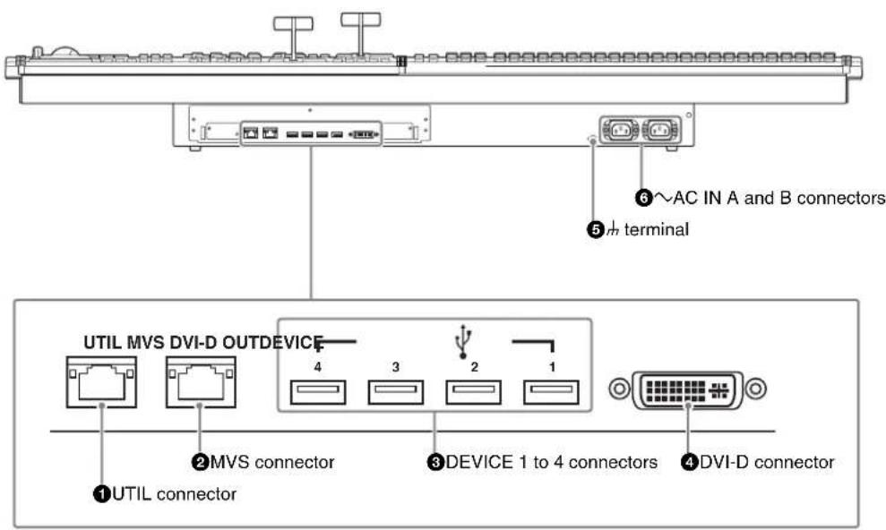
ICP-6520 diagram shown.
①UTIL (utility) connector (RJ-45 compliant)
Intended for future expansion.
②MVS (multi format video switcher) connector (RJ-45 compliant)
Connect to the MVS-6520/6530/3000A/3000 multi format switcher processor.
For details about connecting a DCU and MVE-8000A/9000 multi format DME processor, refer to the User's Guide.
③DEVICE 1 to 4 connectors (USB 2.0 compliant, USB Type-A)
Connect to an ICP-6511 menu panel or USB device. ^1)
④DVI-D connector
Connect to an ICP-6511 menu panel or external monitor. ^1)
⑤ m (signal ground) terminal
Connect to the system ground.
⑥~AC IN (AC power input) A and B connectors (3-pin)
Connect to 100 V to 240 V AC power supply with the optional AC power cords.
The unit is equipped with two power supplies. When A or B power supply is connected, unit operation can proceed.
1) For information about devices that can be connected, contact your Sony representative.
ICP-6511 Menu Panel
The menu panel is optional.
Bottom panel

①DEVICE connector (USB 2.0, USB Type-B)
Connect to the DEVICE 1 connector of the ICP-series control panel.
②DVI-D connector
Connect to the DVI-D output of the ICP-series control panel.
③DC IN connector
Connect to the 12V DC connector of the supplied AC adaptor.
Side panel

DEVICE connector (USB 2.0, USB Type-A)
In general, connect to a USB memory device, and input and output files.
System Configuration
Video Input/Output Systems

flowchart
graph TD
    A["Camera"] --> D["Video signal inputs"]
    B["Playback VTR"] --> D
    C["Character generator"] --> D
    D --> E["MVS-6520/6530/3000A/3000 Multi Format Switcher Processor"]
    E --> F["Video signal outputs"]
    G["ICP-6511 Menu Panel a) "] --> H["ICP-6520/6530/3000/3016 Control Panel b) "]
    H --> F
    I["Preview monitor"] --> F
    J["Program monitor"] --> F
    K["Monitor for multi viewer"] --> F
    L["Recording VTR"] --> F
    M["Removable disk"] --> H
In addition to these devices, a DCU (MKS-8700/2700) or DME processor (MVE-8000A/9000) can be used to extend the system. For more information, refer to the User's Guide.
a) Menu can also be operated by connecting an external monitor in place of the menu panel.
b) ICP-6520 diagram shown.

Device Control Systems

flowchart
graph TD
    A["Other devices on S-Bus data link"] --> B["MVS-6520/6530/3000A/3000 Multi Format Switcher Processor"]
    B --> C["S-BUS"]
    C --> D["MVRS and DDRs Control devices connected using Sony 9-pin VTR, VDCP, or P-Bus protocols (RS-422A)"]
    D --> E["AUX bus control devices and editors (RS-422A)"]
    E --> F["ICP-6511 Menu Panel"]
    F --> G["ICP-6520/6530/3000/3016 Control Panel a)"]
    F --> H["MKS-8080 AUX Bus Remote Panel b"]
    H --> I["MKS-8082 AUX Bus Remote Panel b"]
    I --> J["Other devices on S-Bus data link"]
    style A fill:#f9f,stroke:#333
    style B fill:#ccf,stroke:#333
    style C fill:#cfc,stroke:#333
    style D fill:#fcc,stroke:#333
    style E fill:#ffc,stroke:#333
    style F fill:#cff,stroke:#333
    style G fill:#ffc,stroke:#333
    style H fill:#ffc,stroke:#333
    style I fill:#ffc,stroke:#333
    style J fill:#ffc,stroke:#333

Connecting Devices
This section describes the connection procedure for the following system configuration as an example.
- MVS-6520 or MVS-3000A Switcher Processor (with MKS-6550 Format Converter Board and MKS-6570 Digital Multi Effect Board installed)
- ICP-6520 Control Panel
- ICP-6511 Menu Panel
- Cameras for recording (4)
• VTRs for playback (2)
• Character generator (1)
• Video monitors (2)
• Monitor for multi viewer (1)
Notes
The MVS-3000 does not support the MKS-6570 DME board.
MVS System Connection
MVS-6520/3000A Switcher Processor ICP-6511 Menu Panel
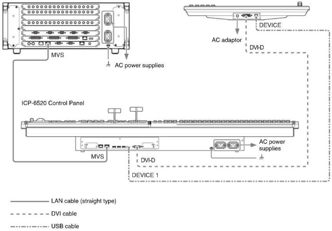
1 Connect the power supply.
Switcher processor
① Connect the m terminal to the system ground.
2Connect the \~AC IN A and B connectors to the 100 V to 240 V AC power supplies using power cords (not supplied).
Control panel
① Connect the 1m terminal to the system ground.
2 Connect the \~AC IN A and B connectors to the 100 V to 240 V AC power supplies using power cords (not supplied).
Menu panel
①Connect the supplied AC adaptor to the DC IN connector, then connect the AC adaptor using a power cord (not supplied).

2 Connect the switcher processor and control panel.
①Connect the MVS connector of the switcher processor and the MVS connector of the control panel using a LAN cable.
3 Connect the control panel and menu panel.
①Connect the DVI-D connector of the control panel and the DVI-D connector of the menu panel using the DVI cable supplied with the menu panel.
②Connect the DEVICE 1 connector of the control panel and the DEVICE connector on the bottom of the menu panel using the USB cable supplied with the menu panel.
Peripheral Device Connection
flowchart
graph TD
    A["Primary INPUTS 1"] -->|2| B["OUTPUTS 1"]
    A -->|3| C["OUTPUTS 2"]
    A -->|4| D["OUTPUTS 5"]
    A -->|5| E["OUTPUTS 6"]
    A -->|6| F["OUTPUTS 7"]
    A -->|7| G["OUTPUTS 8"]
    A -->|8| H["OUTPUTS 9"]
    I["Video signal"] --> A
    J["Key signal"] --> A
    K["Character generator"] --> A
    L["Reference signal generator"] --> M["75 ohm terminator"]
    N["Computer"] --> O["Computer"]
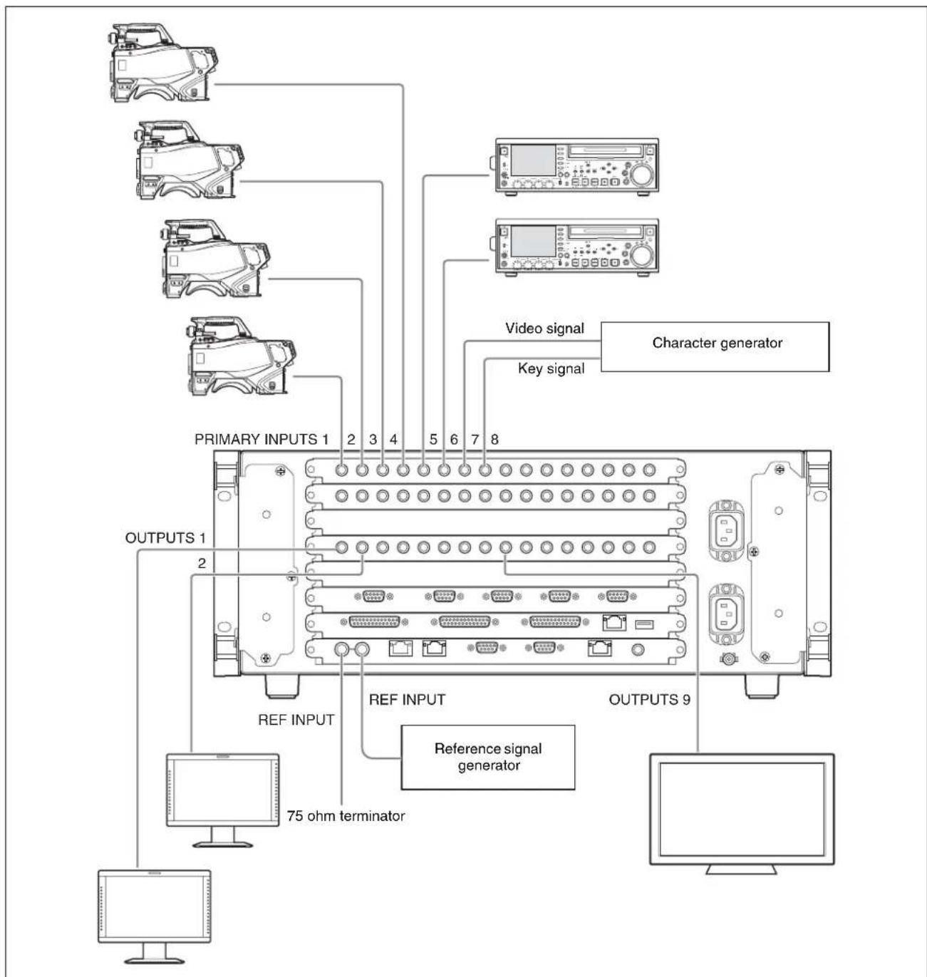
1 Connect devices to the PRIMARY INPUTS of the switcher processor.
①Connect the cameras for recording. In this example, connect four cameras to PRIMARY INPUTS 1 to 4.
2Connect the playback VTRs.
In this example, connect two VTRs to PRIMARY INPUTS 5 and 6.
3 Connect the character generator. In this example, connect to PRIMARY INPUTS 7 and 8.
2 Connect devices to the OUTPUTS of the switcher processor.
①Connect the video monitors. In this example, connect two monitors to OUTPUTS 1 and 2.
②Connect the monitor for multi viewer. In this example, connect to OUTPUTS 9.
3 Connect reference signals to the REF INPUT connectors of the switcher processor.
①Connect one REF INPUT connector to a reference signal generator.
② Terminate the other REF INPUT connector using the supplied 75 ohm terminator.
To use the tally
Set the tally output, using either the SERIAL TALLY connector or the TALLY connector (parallel tally) of the switcher processor

To use an external monitor for menu operations
Instead of the dedicated MVS system ICP-6511 menu panel, you can connect an external monitor and operate the menus from a touch panel or by mouse control.
External monitor connection

Connect the DVI-D connector of the control panel and the DVI-D connector of the external monitor using a DVI cable.
If using a touch panel, connect the DEVICE connector of the control panel and the USB connector of the external monitor using a USB cable.
If using a mouse, connect the mouse to the DEVICE connector of the control panel using a USB cable.
For details about connecting monitors, contact your Sony representative.
Preparation
Preparation Procedure
This section describes the setup required before operation in the MVS system.
Turn on the power (p.16)
System settings
Configure the network (p.19)
Set the type of control panel (p. 20)
Set the signal format (p.21)
Signal settings
Assign input signals (p.22)
Assign output signals (p.24)
Other settings
Make the following system configuration and other settings, as required.
- Configure multi viewer (p.25)
- Settally (p.28)
- Assign buttons required for 8-keyer operation (MVS-6530 only) (p.37)
- Enable background DME wipe (MVS-3000/3000A only) (p.39)
- Set startup mode (p.39)
- Save data to removable disk (p. 41)
- Set simple connection of AUX bus remote panel (p.43)
Turning Power On/Off
After connecting the system, turn on the power using the following procedure.

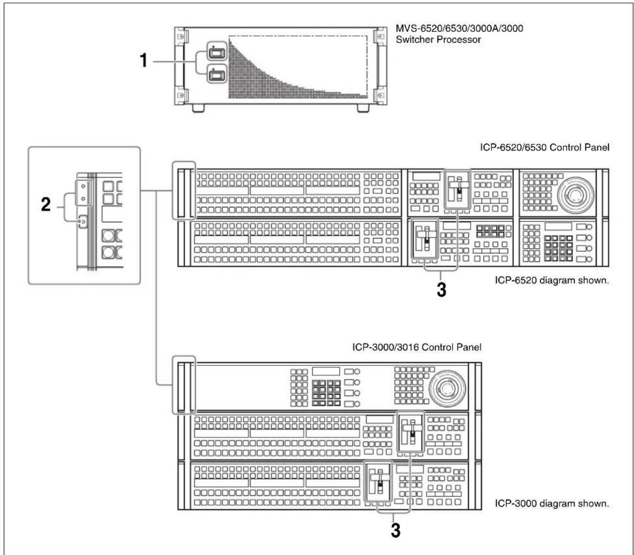
1 Set the POWER A and B switches of the switcher processor to ON ("I" side).
When the switcher processor is turned on, the status indicators for supplies A and B light green.
2 Check that the status indicators on the control panel are lit green, then press the POWER switch.
The POWER switch mark “◀” lights green. The control panel boots in approximately one minute, and the top menu list appears on the menu panel screen.

MVS-6520/3000A/3000 screen shown. On the MVS-6530, the [M/E2] button is also displayed.
3 Pull the fader lever down from top to bottom.

When “Non Sync” or “Sync” appears at the top and bottom stops of the fader lever (non-sync state), the fader lever movement and transitions do not match. Pull the fader level from top to bottom to release non-sync state.
4 Turn on the power of other devices in the system.
Screen saver and panel sleep mode
If no operation is performed for a given time, the menu display screen saver starts. The brightness of all indicators and displays on the control panel also dims.
For details about settings, refer to the User's Guide.
To turn the power off
1 On the menu screen, check that the local disk is not being accessed.
A "local disk" refers to the internal flash memory drive in a control panel.
While the system is accessing the local disk or frame memory external HDD, the indicator on the menu page number button lights red.
Check to make sure the indicator is not lit before turning off the power.
Indicator on the menu page number button
![Page 11 M/E-1 Key1 Type KEY1-4 KEYS-3 2011 Effort: 0 (----) M/E-1 KIF0:0 Free KIF:0 01:00:00:00 Key1 Type LUM C = 8.00 G = 5.00 D = 100.00 Edge Main Mask BH Mode Fill Source Proc Key On Trans Off Trans Priority BLAC WmT OH Mix [30] 1.95 2.93 3.92 6.91 Key Bus Auto Select Key Type Luminance Linear Chroma Color Vector Key Wipe Pattern Clear Mode Key Street Key Position Theta Key Priority Signal Select Key Fill Key Source Key Bus Main Mask Signal Select Self Auto Select Split Default Recall Type Edge Main Mask Processed Key Analyzer Transition Prov 2011](/content/2026/05/911104/images/58b8ce0641980af0c1994595ff9abd1345cf23dd9a8caaa16688db7286052c74.jpg)
Notes
Remove all USB flash memory and other removable disks before turning off the power.
2 Shut down the control panel.
Press the menu page number button and display the top menu window, then press the [Shutdown] button.

MVS-6520/3000A/3000 screen shown. On the MVS-6530, the [M/E2] button is also displayed.


A shutdown confirmation message appears.
Press [Yes] to commence shutdown. The process is completed when the menu screen goes completely black.
Check that the POWER switch indicator “☐” on the control panel has gone out.
Notes
You can forcibly turn off the power to the control panel without following the normal shutdown procedure by pressing and holding the POWER switch for five seconds or longer. If you force shutdown, settings data may not be saved.
3 Set the POWER A and B switches of the switcher processor to OFF ("O" side).
Opening Menus
In the MVS system, basic operations and system setup can be done using the menu.
This section describes how to open the “M/E-1 >Key1 >Type menu (1111)” as an example. Other menus can be opened using the same procedure.
For details about menu operations, refer to the User's Guide.
1 Recall the top menu (top level in menu hierarchy).
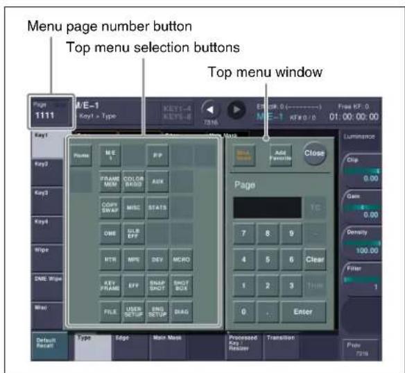
①Press the menu page number button. The top menu window appears.
②Press a top menu selection button.
In this example, press the [M/E1] button.
Memo
You can also open the top menus using the top menu selection buttons in the menu panel.
![Top menu selection buttons MVS-6520/3000A/3000 diagram shown. On the MVS-6530, the [M/E2] button is also displayed.](/content/2026/05/911104/images/decca89bad9c831a3d934bbeef6ff9ed0bdcbcd0b01a3489bb0246fe1b1debe0.jpg)
2 Select a menu.
![VF buttons Page 111 M/E-1 > Key1 > Type KEY1-4 KETS-B 0011 Filter 0 (----) M/E-1 KFE0.0 Free KF1.0 01:00:00 Type Edge Main Mask Luminance Clip C ± 0.00 G + 0.00 D + 100.00 Matte BM Mode Fill Source Prot Key On Trans Off Trans Priority BLAC WMT Off Mix 1 X4 2 X5 3 X6 Key Bus Auto Select [30] Key Type Luminance Linear Chroma Color Vessel Key Wire Pulsure Close Mode Key Shift Key Position Chrome Adjust Key Priority Signal Select Filter Key Fill Key Source Key Bus Matte Signal Sloss Self Auto Select Split Default Retail Type Edge Main Mask Processed Key Resetter Transition HF buttons Primary 0011](/content/2026/05/911104/images/6290cf3e09f18e1b7de4e7a86fe6b6474c2a088747ddbea3fa09c4197cb9a637.jpg)
1 Select a submenu (level 2 in the menu hierarchy) using VF buttons on the left edge. In this example, select [Key1].
②Select a submenu (level 3 in the menu hierarchy) using HF buttons on the bottom edge.
In this example, select [Type].
The M/E-1 >Key1 >Type menu appears.
Memo
You can also open the menu by entering the page number "1111" in the top menu window.
Configuring the Network
When power is turned on, all devices connected to the MVS system LAN are detected and corresponding settings are registered.
1 Display the menu.
① Open the Engineering Setup >System >Network Config menu (7311).
2 Set the group ID.
![Group ID Group ID Device Name 1 PNL1 SWR1 DME1 Group ID Auto Config Define Auto Config Define MVS-6520/6530/3000A screen shown. On the MVS-3000, [DME1] is not displayed.](/content/2026/05/911104/images/41738a8425149e4f2e371588e57781cbd68a91c79642078ac427f36b1d697d8c.jpg)
Network Config menu
①Check the group ID. In this example, check that the group ID is set to "1". If the group ID is not set to "1", press [Group ID] and change the setting.
For details about settings, refer to the User's Guide.
3 Detect the connected devices.
①Press [Auto Config].
②Check the message, then press [Yes]. A list of detected devices appears.

4 Register the list of detected devices.
①Press [Define].
②Check the message, then press [Yes]. The list is registered as the network settings when power is turned on.


Setting the Control Panel Type
You can set the type of the ICP-series control panel connected to the MVS system.
1 Display the menu.
① Open the Engineering Setup >System >Install/Unit Config menu (7316).
2 Select the control panel.
![Device Device Current Information UI Version 1.10 (Jul.12.2013 00:00) PNL1 Version 1.10 (Jul.11.2013 10:30) DCU1 DCU2 SWR1 Version 1.10 (Jul.12.2013 11:46) DME1 Version 1.10 (Jul.12.2013 11:46) Detail Information License Unit Config Textile Package Install Unit Config (Example screen, which may vary from the actual screen display.) MVS-6520/6530/3000A screen shown. On the MVS-3000, [DME1] is not displayed.](/content/2026/05/911104/images/7ec80bd8ee2c1c065608c8ddd18033f6c63ff978d86af6598f1f40356fd6443d.jpg)
Install/Unit Config menu
①Select "PNL1" (control panel) in the [Device] column.
②Press [Unit Config]. The Unit Config menu (7316.8) appears.
3 Set the type of the control panel.

Unit Config menu
①In the
In this example, select [ICP-6520].
Select the type matching the connected control panel.
②Press [Execute].
③ Check the message, then press [Yes]. The system reboots with the applied settings.
Setting Signal Formats
Setting the Signal Format
You can set the signal format and the input reference signal format of each device that is automatically detected. The combinations of signal formats and input reference signals that can be configured are as follows.
Signal format
| System Signal format | ||
| SD system 50 576i | ||
| HD system 50 720P | ||
Input reference signal
| Signal format (HD system) | Input reference signal | ||
| Tri Sync BB | |||
| 720P/50 – Black Burst 50 Sync 50 | |||
| 720P/59.94 59.94 | Black Burst 59.94 Sync 59.94 | ||
| 1080i/50 | 50 | Black Burst 50 | Sync 50 |
| 1080i/59.94 | 59.94 Black Burst 59.94 Sync 59.94 | ||
| 1080PsF/23.976 | 47.952 | - | |
| 1080PsF/24 | 48 | - | |
1 Display the menu.
① Open the Engineering Setup >System >Format menu (7313).
2 Set the formats.
![Device Signal Format Aspect Ref PNL1 1000/59.94 SWR1 1000/59.94 16:9 BB DME1 1000/59.94 16:9 BD FC SWR1 Input1-4 480K59.94 Input5-8 480K59.94 Output1-2 480K59.94 Aspect1 Signal Format Ref Input Format Tri Sync BB Format Converter Clear Execute Signal Format Ref Input Format Execute MVS-6520/6530/3000A screen shown. On the MVS-3000, [DME1] is not displayed.](/content/2026/05/911104/images/4b5bde0b8eeb66965537503ceaa192b4a3b12536e63f66c58debc5703a3996f6.jpg)
Format menu
①Press [Signal Format].
②Press the button for the desired format to set in the pop-up window.
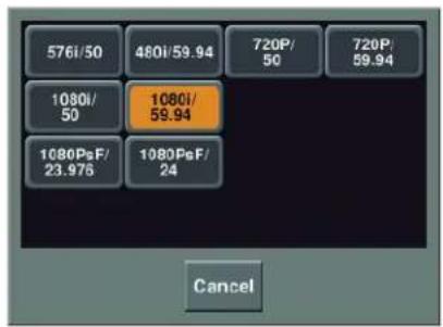
3 Set the input reference signal.
Notes
This setting is available for HD systems only.
Memo
If [BB] is selected, you can set the signal format conversion in the format converter (when MKS-6550 Format Converter Board is installed). If [Tri Sync] is selected, the format converter cannot be used.
For details about format converter settings and operations, refer to the User's Guide.

4 Apply and save the settings.
①Press [Execute].
②Check the message, then press [Yes].
A progress bar is displayed during the configuration.
The system restarts when the configuration is completed.
Setting the Screen Aspect Ratio
You can set the screen aspect ratio for signals handled by the switcher processor and DME to either 16:9 or 4:3.
1 Display the menu.
① Open the Engineering Setup >System >Format menu (7313).
②Press [Aspect]. The Aspect menu (7313.1) appears.
2 Set the aspect ratio.

Aspect menu
①In the
16:9: Sets 16:9 aspect ratio.
4:3: Sets 4:3 aspect ratio.
Independ: Sets the aspect ratio for each of the switcher processor banks and DME channels.
Memo
If [Independ] is selected, press [Switcher Aspect] or [DME Aspect] to set the aspect ratio.
3 Apply and save the settings.
①Press [Aspect Execute].
②Check the message, then press [Yes].
Assigning Signals to Cross-Point Buttons
To select input signals using cross-point buttons, the signals must be assigned to each of the cross-point buttons in advance. You can assign two signals (video and key) as a pair to each cross-point button.
Setting the Signal Name
1 Display the menu.
① Open the Engineering Setup >Panel >Xpt Assign menu (7322).
②Press [Src Name/Src Color].
The Src Name/Src Color menu (7322.6) appears.
2 Set the signal name.

Src Name/Src Color menu
①Select the signal to be set in the [Src#] column. In this example, select "1".
②Press [Source Name].
③Enter the name of the source signal in the keyboard window.
In this example, enter "CAM1".

Keyboard window
4Press [Enter].
⑤ Repeat steps ① to ④ as required to assign other signals.
Notes
Up to 16 characters can be entered for signal names.
Memo
You can also set the color for cross-point buttons assigned with signals.
Assigning Pair Signals to Cross-Point Buttons
You can assign video and key signals, shown below, as a pair to each cross-point button.
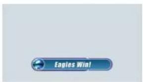
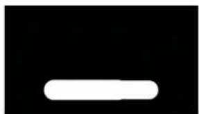
Video signal Key signal
natural_image
Simple white rounded rectangle on black background (no text or symbols)1 Display the menu.
① Open the Engineering Setup >Panel >Xpt Assign menu (7322).
②Press [Main, V/K Pair Assign]. The Main, V/K Pair Assign menu (7322.5) appears.
2 Assign a video signal to the cross-point button.

Main, V/K Pair Assign menu
① In the [V/K] column of the list on the left, select the number of the cross-point button.
In this example, select "1".
②In the
③ In the list on the right, select the signal you want to assign as the video signal.
In this example, select "CAM1".
④ In the
Memo
When assigning the same signal to the video and key, turn on both [Video] and [Key] in the
3 Assign a key signal to the cross-point button.
①In the
②In the list on the right, select the signal you want to assign as the key signal.
In this example, select "Key1".
③In the
Memo
You can also edit the lists using [Insert] and [Delete] in the
4 Repeat steps 2 and 3 as required to assign other signals.
For details about using assigned pair signals using a keyer, see "Entering Titles using Luminance Keys" (p. 53).

Assigning M/E Reentry Input Signals to Cross-Point Buttons
A video signal created on one bank can be used as the input signal on another bank, for example, an image created on the M/E-1 bank can be used as the background on the PGM/PST bank. These signals are referred to as “M/E reentry input” signals.
On the ICP-3000/3016, to select an M/E reentry input signal, the signal must be assigned to a cross-point button beforehand.
This section describes the procedure for setting the M/E-1 reentry input.
On the ICP-6520/6530, this setting is not required as signals can be assigned using the reentry buttons on the control panel.
1 Display the menu.
① Open the Engineering Setup >Panel >Xpt Assign menu (7322).
②Press [Main, V/K Pair Assign]. The Main, V/K Pair Assign menu (7322.5) appears.
2 Assign an M/E-1 reentry signal to a cross-point button.

Main, V/K Pair Assign menu
①In the [V/K] column of the list on the left, select the number of the cross-point button. Select the button number to which you want to assign the M/E-1 reentry input signal.
②In the
③In the list on the right, select "M/E1OUT1".
④ In the
Assigning Output Signals
You can set the signals output to the connected devices on the OUTPUTS of the switcher processor.
Setting Monitor Outputs
This section describes the procedure for setting up monitors for checking final program output video (program output) and for checking preview video (preview output).
1 Display the menu.
① Open the Engineering Setup >Switcher >Output menu (7333).
②Press [Output Assign]. The Output Assign menu (7333.1) appears.
2 Set a monitor for program output.
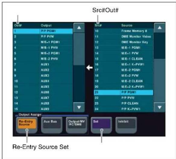
Output Assign menu
①In the
②In the [Out#] column in the list on the left, select the number for the OUTPUTS connector connected to the monitor. In this example, select "1".
③In the [Src#] column in the list on the right, select the program output. In this example, select "P/P PGM1".
4Press [Set]. The output signal is assigned, and "P/P PGM1" is displayed for output 1 in the [Out#] column.
3 Set a monitor for preview output.
①In the
② In the [Out#] column in the list on the left, select the number for the OUTPUTS connector connected to the monitor.
In this example, select "2".
③In the [Src#] column in the list on the right, select the preview output.
In this example, select "P/P PVW".
4Press [Set].
The output signal is assigned, and "P/P PVW" is displayed for output 2 in the [Out#] column.
Using Multi Viewer
The screen of a monitor connected to the MVS system can be split to view multiple video signals simultaneously.
The screen can be split into four, ten, or sixteen subscreens.

natural_image
Four-panel image showing a yellow rapeseed field, a white windmill, a windmill on a hillside, and a distant road with a white tower (no visible text or symbols)Split into four
| 1 | 2 |
| 3 | 4 |
Subscreen signals

natural_image
Collage of landscape photos including windmill, fields, hills, and circular objects (no text or symbols)Split into ten
| 1 | 2 | ||
| 3 | 4 | 5 | 6 |
| 7 | 8 | 9 | 10 |
Subscreen signals
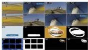
natural_image
Grid of 3D-rendered landscape images showing landscapes, buildings, and circular objects (no text or symbols)| 1 | 2 | 3 | 4 |
| 5 | 6 | 7 | 8 |
| 9 | 10 | 11 | 12 |
| 13 | 14 | 15 | 16 |
Subscreen signalsSplit into sixteen
There are two multi viewer systems, Multi Viewer 1 and 2, to which you can assign signals independently.
This section describes the procedure for setting Multi Viewer 1.
Setting Multi Viewer Output
To use multi viewer, you must assign the multi viewer output to the OUTPUTS connector connected to the monitor in advance.
1 Display the menu.
① Open the Engineering Setup >Switcher >Output menu (7333).
②Press [Output Assign].
The Output Assign menu (7333.1) appears.

2 Set the multi viewer outputs.

Output Assign menu
① In the
Configuring Multi Viewer
1 Display the menu.
① Open the Engineering Setup >Switcher >Output menu (7333).
②Press [Multi Viewer]. The Multi Viewer menu (7333.9) appears.
2 Set the display method of the screen.

Multi Viewer menu
①In the
②In the
Split 4: Splits the screen into four windows.
Split 10: Splits the screen into ten windows.
Split 16: Splits the screen into sixteen windows.
Memo
You can specify names and borders for subscreens using [Name Display] and [Border Enable].
Assigning Signals to Subscreens
1 Display the menu.
① Open the Engineering Setup >Switcher >Output menu (7333).
②Press [Multi Viewer].
③Press [Source/Output Assign]. The Source/Output Assign menu (7333.10) appears.
2 Assign an output signal to a subscreen.

Source/Output Assign menu
① In the
② In the [Win#] column of the list on the left, select the number of the subscreen.
In this example, select "1".
③ In the list on the right, select the signal you want to assign.
In this example, select "P/P PVW".
④Press [Set].
3 Assign an input signal to a subscreen.
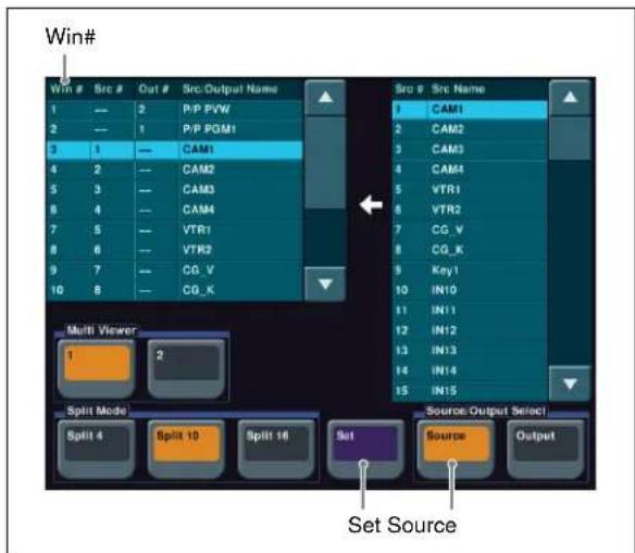
Source/Output Assign menu
① In the
② In the [Win#] column of the list on the left, select the number of the subscreen.
In this example, select "3".
③In the list on the right, select the signal you want to assign.
In this example, select "CAM1".
④Press [Set].
4 Repeat steps 2 and 3 as required to assign other signals to other subscreens.
Setting Multi Viewer Tally Output
To display the tally on the multi viewer screen, you must set the same tally type as specified in step 2 of "Setting Serial Tally" (p. 28).
1 Display the menu.
① Open the Engineering Setup >Panel >Operation menu (7326).
②Press [Button Tally]. The Button Tally menu (7326.9) appears.
2 Set the tally type.

Button Tally menu
① In the
②Press [Execute].
Notes
To display a tally on the multi viewer screen, select the tally type from [R1] to [R8]. If you set [Independ], the tally is not shown.
When any of the red tally types [R1] to [R8] is selected, the corresponding green tally is automatically set. For example, when [R1] is selected, [G1] is automatically set as green tally. Note that you must set the tally type [G1] in step 2 of “Setting Serial Tally” (p. 28) beforehand.

Setting Tally
Setting Parallel Tally
The red tallies for PRIMARY INPUTS 1 to 48 are assigned to the TALLY connector on the switcher processor by default.
For details about changing the assignment settings, refer to the User's Guide.
Setting Serial Tally
Set the red tally of the program output (P/P PGM1) and the green tally of the preview output (P/P PVW) to be output from the SERIAL TALLY connector of the switcher processor.
This section describes the procedure when "P/P PGM1" is assigned to the OUTPUTS 1 connector and "P/P PVW" is assigned to the OUTPUTS 2 connector.
1 Set the position of the MVS system in S-Bus space.
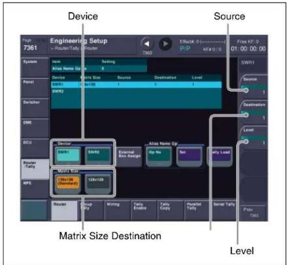
Router menu
① Open the Engineering Setup >Router/Tally >Router menu (7361).
②In the
③ In the
④ Set each of the [Source], [Destination], and [Level] parameters to “1”.
2 Set the tally generation reference.

Tally Enable menu

New menu
① Open the Engineering Setup >Router/Tally >Tally Enable menu (7364).
②Check the tally settings for the program output. If the settings of "OUT001" are as follows, you do not need to change the settings. Proceed to step ⑦.
| Setting | Destination | Level | Tally | Type | Enable |
| Value | OUT | 001 | 1 | R1 | Enable |
③Press [New].
The New menu (7364.1) appears.
④ Set each of the [Destination Address], [Destination Level], and [Tally Type] parameters to “1”.
⑤In the
6Press [Execute].

⑦In the Tally Enable menu (7364), check the tally settings for the preview output. If the settings of "OUT002" are as follows, you do not need to change the settings. Proceed to step 3.
| Setting | Destination | Level | Tally | Type | Enable |
| Value | OUT002 | 1 | G1 | Enable |
⑧ Repeat steps ③ to ⑥ to make settings for the preview output. In step ④, set the [Destination Address] parameter to “2”, [Destination Level] parameter to “1”, and [Tally Type] parameter to “2”.
3 Set the serial tally output.
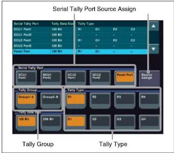
Serial Tally menu
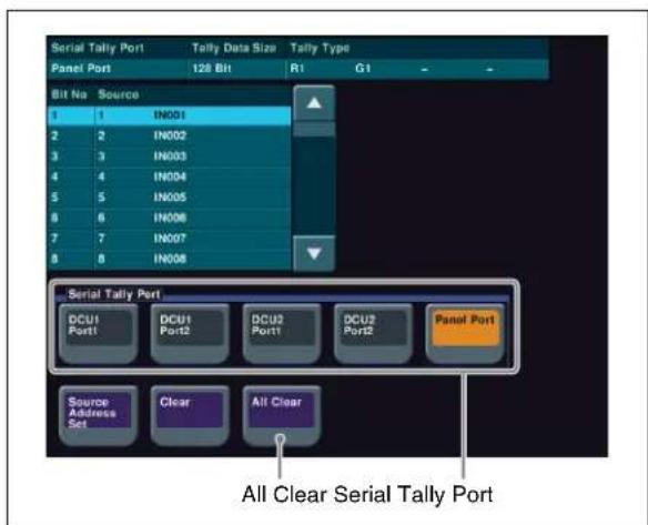
Source Assign menu
① Open the Engineering Setup >Router/Tally >Serial Tally menu (7367).
② In the
③ Set the tally type.
In this example, select [Group1-4] in the
Turn off [R2] to [R4] and [G2] to [G4] in [Group1-4], and [R5] to [R8] and [G5] to [G8] in [Group 5-8].
④Press [Source Assign].
The Source Assign menu (7367.1) appears.
⑤ In the
In this example, select [Panel Port].
⑥Press [Default Recall].
⑦ Check the message, then press [Yes].
The source addresses assigned to each of the serial tally bits are set to the default.
If you use other than the default values for serial tally bits, change the source address settings.
For details about settings, refer to the User's Guide.
Memo
To output parallel tallies from a DCU, display the Engineering Setup >Router/Tally >Parallel Tally menu (7366) in step 3 and make settings.
For details about settings, refer to the User's Guide.
Input/outputs for MVS-6520/6530/3000A/3000 system assigned to S-Bus matrix
Matrix size: 136 x 138
- Source
| No. Source | |
| 1 | Primary 1 |
| 2 | Primary 2 |
| 3 | Primary 3 |
| 4 | Primary 4 |
| 5 | Primary 5 |
| 6 | Primary 6 |
| 7 | Primary 7 |
| 8 | Primary 8 |
| 9 | Primary 9 |
| 10 | Primary 10 |
| 11 | Primary 11 |
| 12 | Primary 12 |
| 13 | Primary 13 |
| 14 | Primary 14 |
| 15 | Primary 15 |
| 16 | Primary 16 |

| No. Source | |
| 17 Primary | 17 |
| 18 Primary | 18 |
| 19 Primary | 19 |
| 20 Primary | 20 |
| 21 Primary | 21 |
| 22 Primary | 22 |
| 23 Primary | 23 |
| 24 Primary | 24 |
| 25 Primary | 25 |
| 26 Primary | 26 |
| 27 Primary | 27 |
| 28 Primary | 28 |
| 29 Primary | 29 |
| 30 Primary | 30 |
| 31 Primary | 31 |
| 32 Primary | 32 |
| 33 Primary | 33 a) |
| 34 Primary | 34 a) |
| 35 Primary | 35 a) |
| 36 Primary | 36 a) |
| 37 Primary | 37 a) |
| 38 Primary | 38 a) |
| 39 Primary | 39 a) |
| 40 Primary | 40 a) |
| 41 Primary | 41 a) |
| 42 Primary | 42 a) |
| 43 Primary | 43 a) |
| 44 Primary | 44 a) |
| 45 Primary | 45 a) |
| 46 Primary | 46 a) |
| 47 Primary | 47 a) |
| 48 Primary | 48 a) |
| 49 | |
| 50 | |
| 51 | |
| 52 | |
| 53 | |
| 54 | |
| 55 | |
| 56 | |
| 57 | |
| 58 | |
| 59 | |
| 60 | |
| 61 | |
| No. Source | |
| 62 | |
| 63 | |
| 64 | |
| 65 | |
| 66 | |
| 67 | |
| 68 | |
| 69 | |
| 70 | |
| 71 | |
| 72 | |
| 73 FC 1 | |
| 74 FC 2 | |
| 75 FC 3 | |
| 76 FC 4 | |
| 77 FC 5 | |
| 78 FC 6 | |
| 79 FC 7 | |
| 80 FC 8 | |
| 81 Black | |
| 82 White | |
| 83 Color Bkgd 1 | |
| 84 Color Bkgd 2 | |
| 85 Frame Memory 1 | |
| 86 Frame Memory 2 | |
| 87 Frame Memory 3 | |
| 88 Frame Memory 4 | |
| 89 Frame Memory 5 | |
| 90 Frame Memory 6 | |
| 91 Frame Memory 7 | |
| 92 Frame Memory 8 | |
| 93 | |
| 94 | |
| 95 DME Monitor Video b) | |
| 96 DME Monitor Key b) | |
| 97 M/E-1 Out 1 | |
| 98 M/E-1 Out 2 | |
| 99 M/E-1 Out 3 | |
| 100 M/E-1 Out 4 | |
| 101 | |
| 102 | |
| 103 | |
| 104 | |
| 105 M/E-2 Out 1 a) | |
| 106 M/E-2 Out 2 a) | |
| No. Source | |
| 107 M/E-2 | Out 3 a) |
| 108 M/E-2 | Out 4 a) |
| 109 | |
| 110 | |
| 111 | |
| 112 | |
| 113 | |
| 114 | |
| 115 | |
| 116 | |
| 117 | |
| 118 | |
| 119 | |
| 120 | |
| 121 P/P Out 1 | |
| 122 P/P Out 2 | |
| 123 P/P Out 3 | |
| 124 P/P Out 4 | |
| 125 | |
| 126 | |
| 127 | |
| 128 | |
| 129 DME 1 b) c) | |
| 130 DME 2 b) c) | |
| 131 | |
| 132 | |
| 133 DME 5 c) | |
| 134 DME 6 c) | |
| 135 DME 7 c) | |
| 136 DME 8 c) | |
| 137 | |
| 138 | |
a) MVS-6530 only
b) MVS-6520/6530/3000A only
c) Virtual DME output signals for tally
- Destination (Bus)
| No. Destination | ||||
| 1 | O a) | u | t | 1 |
| 2 | O a) | u | t | 2 |
| 3 | O a) | u | t | 3 |
| 4 | O a) | u | t | 4 |
| 5 | O a) | u | t | 5 |
| 6 | O a) | u | t | 6 |
| 7 | O a) | u | t | 7 |
a) If AUX or Edit Preview is assigned to outputs 1 to 24 (MVS-6530), outputs 1 to 16 (MVS-6520/3000A), or outputs 1 to 12 (MVS-3000), the outputs act as a bus (destination) controlled by the router remote panel.
b) MVS-6530 only
c) MVS-6520/6530/3000A only
Matrix size: 128 x 128
Numbers in parentheses indicate the number for 136 x 138 matrix size.
- Source
| No. Source | |||||
| 1 | P | r | i | m | a |
| 2 | P | r | i | m | a |
| 3 | P | r | i | m | a |
| 4 | P | r | i | m | a |
| 5 | P | r | i | m | a |
| 6 | P | r | i | m | a |
| 7 | P | r | i | m | a |
| 8 | P | r | i | m | a |
| 9 | P | r | i | m | a |
| 10 Primary | 10 | ||||
| 11 Primary | 11 | ||||
| 12 Primary | 12 | ||||
| 13 Primary | 13 | ||||
| 14 Primary | 14 | ||||
| 15 Primary | 15 | ||||
| 16 Primary | 16 | ||||
| 17 Primary | 17 | ||||
| 18 Primary | 18 | ||||
| 19 Primary | 19 | ||||
| 20 Primary | 20 | ||||
| 21 Primary | 21 | ||||
| 22 Primary | 22 | ||||
| 23 Primary | 23 | ||||
| 24 Primary | 24 | ||||
| 25 Primary | 25 | ||||
| 26 Primary | 26 | ||||
| 27 Primary | 27 | ||||
| 28 Primary | 28 | ||||
| 29 Primary | 29 | ||||
| 30 Primary | 30 | ||||
| 31 Primary | 31 | ||||
| 32 Primary | 32 | ||||
| 33 Primary | 33 | a) | |||
| 34 Primary | 34 | a) | |||
| 35 Primary | 35 | a) | |||
| 36 Primary | 36 | a) | |||
| 37 Primary | 37 | a) | |||
| 38 Primary | 38 | a) | |||
| 39 Primary | 39 | a) | |||
| 40 Primary | 40 | a) | |||
| No. Source | ||
| 41 Primary | 41 | a) |
| 42 Primary | 42 | a) |
| 43 Primary | 43 | a) |
| 44 Primary | 44 | a) |
| 45 Primary | 45 | a) |
| 46 Primary | 46 | a) |
| 47 Primary | 47 | a) |
| 48 Primary | 48 | a) |
| 49 | y | 5 |
| 50 | y | 6 |
| 51 | y | 7 |
| 52 | y | 8 |
| 53 | y | 9 |
| 54 | ||
| 55 | ||
| 56 | ||
| 57 | ||
| 58 | ||
| 59 | ||
| 60 | ||
| 61 | ||
| 62 | ||
| 63 | ||
| 64 | ||
| 65 | ||
| 66 | ||
| 67 | ||
| 68 | ||
| 69 | ||
| 70 | ||
| 71 | ||
| 72 | ||
| 73 FC 1 | ||
| 74 FC 2 | ||
| 75 FC 3 | ||
| 76 FC 4 | ||
| 77 FC 5 | ||
| 78 FC 6 | ||
| 79 FC 7 | ||
| 80 FC 8 | ||
| 81 Black | ||
| 82 White | ||
| 83 Color Bkgd 1 | ||
| 84 Color Bkgd 2 | ||
| 85 Frame Memory 1 | ||


| No. Source | |
| 86 Frame | Memory 2 |
| 87 Frame | Memory 3 |
| 88 Frame | Memory 4 |
| 89 Frame | Memory 5 |
| 90 Frame | Memory 6 |
| 91 Frame | Memory 7 |
| 92 Frame | Memory 8 |
| 93 | |
| 94 | |
| 95 DME Monitor Video b) | |
| 96 DME Monitor Key b) | |
| 97 M/E-1 Out 1 | |
| 98 M/E-1 Out 2 | |
| 99 M/E-1 Out 3 | |
| 100 M/E-1 Out 4 | |
| 101 | |
| 102 | |
| 103 M/E-2 Out 1 (105) a) | |
| 104 M/E-2 Out 2 (106) a) | |
| 105 M/E-2 Out 3 (107) a) | |
| 106 M/E-2 Out 4 (108) a) | |
| 107 | |
| 108 | |
| 109 | |
| 110 | |
| 111 | |
| 112 | |
| 113 | |
| 114 | |
| 115 P/P Out 1 (121) | |
| 116 P/P Out 2 (122) | |
| 117 P/P Out 3 (123) | |
| 118 P/P Out 4 (124) | |
| 119 | |
| 120 | |
| 121 DME 1 (129) b) c) | |
| 122 DME 2 (130) b) c) | |
| 123 | |
| 124 | |
| 125 DME 5 (133) c) | |
| 126 DME 6 (134) c) | |
| 127 DME 7 (135) c) | |
| 128 DME 8 (136) c) | |
a) MVS-6530 only
b) MVS-6520/6530/3000A only
c) Virtual DME output signals for tally
- Destination (Bus)
| No. Destination | |
| 1 Out 1 | a) |
| 2 Out 2 | a) |
| 3 Out 3 | a) |
| 4 Out 4 | a) |
| 5 Out 5 | a) |
| 6 Out 6 | a) |
| 7 Out 7 | a) |
| 8 Out 8 | a) |
| 9 Out 9 | a) |
| 10 Out 10 | a) |
| 11 Out 11 | a) |
| 12 Out 12 | a) |
| 13 Out 13 | a) |
| 14 Out 14 | a) |
| 15 Out 15 | a) |
| 16 Out 16 | a) |
| 17 Out 17 | a) b) |
| 18 Out 18 | a) b) |
| 19 Out 19 | a) b) |
| 20 Out 20 | a) b) |
| 21 Out 21 | a) b) |
| 22 Out 22 | a) b) |
| 23 Out 23 | a) b) |
| 24 Out 24 | a) b) |
| 25 Out 25 | b) |
| 26 Out 26 | b) |
| 27 Out 27 | b) |
| 28 Out 28 | b) |
| 29 Out 29 | b) |
| 30 Out 30 | b) |
| 31 Out 31 | b) |
| 32 Out 32 | b) |
| 33 | |
| 34 | |
| 35 | |
| 36 | |
| 37 | |
| 38 | |
| 39 | |
| 40 | |
| 41 | |
| 42 | |
| 43 | |
| 44 | |
| 45 | |
| 46 | |
| 47 | |
| 48 | |
| 49 | |
| 50 | |
| 51 | |
| 52 | |
| 53 | |
| 54 | |
| 55 | |
| 56 | |
| 57 M/E-1 Bkgd A | |
| 58 M/E-1 Bkgd B | |
| 59 M/E-1 Utility 1 | |
| 60 | |
| 61 M/E-1 Key 1 Fill | |
| 62 M/E-1 Key 1 Source | |
| 63 M/E-1 Key 2 Fill | |
| 64 M/E-1 Key 2 Source | |
| 65 M/E-1 Key 3 Fill | |
| 66 M/E-1 Key 3 Source | |
| 67 M/E-1 Key 4 Fill | |
| 68 M/E-1 Key 4 Source | |
| 69 M/E-2 Bkgd A (72) b) | |
| 70 M/E-2 Bkgd B (73) b) | |
| 71 M/E-2 Utility 1 (74) b) | |
| 72 | |
| 73 M/E-2 Key 1 Fill (76) b) | |
| 74 M/E-2 Key 1 Source (77) b) | |
| 75 M/E-2 Key 2 Fill (78) b) | |
| 76 M/E-2 Key 2 Source (79) b) | |
| 77 M/E-2 Key 3 Fill (80) b) | |
| 78 M/E-2 Key 3 Source (81) b) | |
| 79 M/E-2 Key 4 Fill (82) b) | |
| 80 M/E-2 Key 4 Source (83) b) | |
| 81 | |
| 82 | |
| 83 | |
| 84 | |
| 85 P/P Key 5 Fill (91) b) | |
| 86 P/P Key 5 Source (92) b) | |
| 87 P/P Key 6 Fill (93) b) | |
| 88 P/P Key 6 Source (94) b) | |
| 89 P/P Key 7 Fill (95) b) | |
| No. Destination | |
| 90 P/P Key 7 Source (96) | b) |
| 91 P/P Key 8 Fill (97) | b) |
| 92 P/P Key 8 Source (98) | b) |
| 93 P/P Bkgd A (102) | |
| 94 P/P Bkgd B (103) | |
| 95 P/P Utility 1 (104) | |
| 96 | |
| 97 P/P Key 1 Fill (106) | |
| 98 P/P Key 1 Source (107) | |
| 99 P/P Key 2 Fill (108) | |
| 100 P/P Key 2 Source (109) | |
| 101 P/P Key 3 Fill (110) | |
| 102 P/P Key 3 Source (111) | |
| 103 P/P Key 4 Fill (112) | |
| 104 P/P Key 4 Source (113) | |
| 105 | |
| 106 | |
| 107 | |
| 108 Frame Memory Source 1 (119) | |
| 109 Frame Memory Source 2 (120) | |
| 110 | |
| 111 | |
| 112 DME 1 Video (123) | c) |
| 113 DME 1 Key (124) | c) |
| 114 DME 2 Video (125) | c) |
| 115 DME 2 Key (126) | c) |
| 116 | |
| 117 | |
| 118 | |
| 119 | |
| 120 DME 5 Video (131) | |
| 121 DME 5 Key (132) | |
| 122 DME 6 Video (133) | |
| 123 DME 6 Key (134) | |
| 124 DME 7 Video (135) | |
| 125 DME 7 Key (136) | |
| 126 DME 8 Video (137) | |
| 127 DME 8 Key (138) | |
| 128 | |
a) If AUX or Edit Preview is assigned to outputs 1 to 24 (MVS-6530), outputs 1 to 16 (MVS-6520/3000A), or outputs 1 to 12 (MVS-3000), the outputs act as a bus (destination) controlled by the router remote panel.
b) MVS-6530 only
c) MVS-6520/6530/3000A only

Serial tally bit assignment
| Bit No. Source | |||||
| 1 | P | r | i | m | a |
| 2 | P | r | i | m | a |
| 3 | P | r | i | m | a |
| 4 | P | r | i | m | a |
| 5 | P | r | i | m | a |
| 6 | P | r | i | m | a |
| 7 | P | r | i | m | a |
| 8 | P | r | i | m | a |
| 9 | P | r | i | m | a |
| 10 Primary | 10 | ||||
| 11 Primary | 11 | ||||
| 12 Primary | 12 | ||||
| 13 Primary | 13 | ||||
| 14 Primary | 14 | ||||
| 15 Primary | 15 | ||||
| 16 Primary | 16 | ||||
| 17 Primary | 17 | ||||
| 18 Primary | 18 | ||||
| 19 Primary | 19 | ||||
| 20 Primary | 20 | ||||
| 21 Primary | 21 | ||||
| 22 Primary | 22 | ||||
| 23 Primary | 23 | ||||
| 24 Primary | 24 | ||||
| 25 Primary | 25 | ||||
| 26 Primary | 26 | ||||
| 27 Primary | 27 | ||||
| 28 Primary | 28 | ||||
| 29 Primary | 29 | ||||
| 30 Primary | 30 | ||||
| 31 Primary | 31 | ||||
| 32 Primary | 32 | ||||
| 33 Primary | 33 | a) | |||
| 34 Primary | 34 | a) | |||
| 35 Primary | 35 | a) | |||
| 36 Primary | 36 | a) | |||
| 37 Primary | 37 | a) | |||
| 38 Primary | 38 | a) | |||
| 39 Primary | 39 | a) | |||
| 40 Primary | 40 | a) | |||
| 41 Primary | 41 | a) | |||
| 42 Primary | 42 | a) | |||
| 43 Primary | 43 | a) | |||
| 44 Primary | 44 | a) | |||
| Bit No. Source | ||
| 45 Primary | 45 | a) |
| 46 Primary | 46 | a)1 |
| 47 Primary | 47 | a)2 |
| 48 Primary | 48 | a)3 |
| 49 | y | 4 |
| 50 | y | 5 |
| 51 | y | 6 |
| 52 | y | 7 |
| 53 | y | 8 |
| 54 | y | 9 |
| 55 | ||
| 56 | ||
| 57 | ||
| 58 | ||
| 59 | ||
| 60 | ||
| 61 | ||
| 62 | ||
| 63 | ||
| 64 | ||
| 65 | ||
| 66 | ||
| 67 | ||
| 68 | ||
| 69 | ||
| 70 | ||
| 71 | ||
| 72 | ||
| 73 FC 1 | ||
| 74 FC 2 | ||
| 75 FC 3 | ||
| 76 FC 4 | ||
| 77 FC 5 | ||
| 78 FC 6 | ||
| 79 FC 7 | ||
| 80 FC 8 | ||
| 81 Black | ||
| 82 White | ||
| 83 Color Bkgd 1 | ||
| 84 Color Bkgd 2 | ||
| 85 Frame Memory 1 | ||
| 86 Frame Memory 2 | ||
| 87 Frame Memory 3 | ||
| 88 Frame Memory 4 | ||
| 89 Frame Memory 5 | ||

| Bit No. Source | |
| 90 Frame | Memory 6 |
| 91 Frame | Memory 7 |
| 92 Frame | Memory 8 |
| 93 | |
| 94 | |
| 95 DME | Monitor Video b) |
| 96 DME | Monitor Key b) |
| 97 M/E-1 | Out 1 |
| 98 M/E-1 | Out 2 |
| 99 M/E-1 | Out 3 |
| 100 M/E-1 | Out 4 |
| 101 | |
| 102 | |
| 103 M/E-2 | Out 1 a) |
| 104 M/E-2 | Out 2 a) |
| 105 M/E-2 | Out 3 a) |
| 106 M/E-2 | Out 4 a) |
| 107 | |
| 108 | |
| 109 | |
| 110 | |
| 111 | |
| 112 | |
| 113 | |
| 114 | |
| 115 P/P Out 1 | |
| 116 P/P Out 2 | |
| 117 P/P Out 3 | |
| 118 P/P Out 4 | |
| 119 | |
| 120 | |
| 121 DME 1 | b) c) |
| 122 DME 2 | b) c) |
| 123 | |
| 124 | |
| 125 DME 5 | c) |
| 126 DME 6 | c) |
| 127 DME 7 | c) |
| 128 DME 8 | c) |
a) MVS-6530 only
b) MVS-6520/6530/3000A only
c) Virtual DME output signals for tally
Assigning 8-Keyer Buttons
(MVS-6530 only)
On the MVS-6530 (3M/E processor), eight keyers can be used in the PGM/PST banks. The buttons required for key 5 to 8 operation are not pre-assigned by default, and must be assigned using the following procedure.
For details about operations using assigned buttons, refer to the User's Guide.
Assigning Key 5 to Key 8 to 1st Row Buttons
You can make assignments so that key 5 to key 8 can be selected using buttons in the 1st row of the cross-point control block ( p.46 ).
1 Display the menu.
① Open the Engineering Setup >Panel >Operation >Key/AUX/Function Assign menu (7326.13).
2 Select the target bank.

Key/AUX/Function Assign menu
① In the


3 Assign a key to a button number.
①In the [Button#] column of the list on the left, select the button number.
In this example, select "5".
Numbers “5” to “8” are set to “No Assign” by factory default.
②In the list on the right, select the key to assign. In this example, select [KEY5].
③Press [Set].
④ Repeat steps ① to ③ to assign [KEY6] to [KEY8] to button numbers "6" to "8", respectively.
Assigning Key Selection Functions to Next Transition Selection Buttons
You can make assignments so that key 1 to key 8 can be selected using next transition selection buttons in the transition control block.
1 Display the menu.
① Open the Engineering Setup >Panel >Config >Transition Module menu (7321.9).
2 Select the target bank.

Transition Module menu
①In the
3 Assign a key to a button.
①In the button diagram on the left, select the target button. In this example, select the [KEY1] button in [Next Transition].
②In the list on the right, select the key to assign. In this example, select [KEY1/5].
③Press [Set].
④ Repeat steps ① to ③ to assign [KEY2/6], [KEY3/7], and [KEY4/8] to buttons [KEY2], [KEY3], and [KEY4], respectively.
4 Assign the [SHIFT] and [ADD] functions to buttons.
①In the button diagram on the left, select the target button. In this example, select a blank button.
②In the list on the right, select [SHIFT].
③Press [Set].
④ Repeat steps ① to ③ to assign [ADD].
Enabling Background DME Wipes
(MVS-3000/3000A only)
On the MVS-3000 and on the MVS-3000A without an MKS-6570 installed, only the background DME wipe or key 1 can be enabled at any one time. The key 1 is enabled by default, and you must change the setting to use the background DME wipe.
This setting can be made for each of the M/E and PGM/PST banks. This section describes the procedure for enabling the DME wipe on the M/E-1 bank.
1 Display the menu.
① Open the Engineering Setup >Switcher >Config menu (7331).
2 Enable the background DME wipe.

Config menu
1 Select the target M/E or PGM/PST bank in the [Bank] column.
In this example, select "M/E-1".
②In the
Memo
To enable key 1, select [Key1].
For details about switching backgrounds using DME wipes, see "Setting Picture-in-Picture (DME Wipe)" (P. 50).
Setting the Startup State
Selecting the Startup Mode at Power On
You can set the startup mode when power is turned on to one of the following three options.
- Settings valid when power is last turned off
- User default settings
• Factory default settings
This setting is available for the switcher processor, control panel, and DME.
1 Display the menu.
① Open the Engineering Setup >System >Start Up menu (7314).
2 Select the device to set.
![Device Start Up Mode Device PNL1 SWR1 DME1 Start Up Mode Setup User User User Custom Custom User User Initial Status Setup Resume Custom Power On File Load Setup Define Init Status Define Setup Initial Status Execute MVS-6520/6530/3000A screen shown. On the MVS-3000, [DME1] is not displayed.](/content/2026/05/911104/images/94b28e38b99df7ee3506f1e99f2ee6b203d4b19854bb3dcf7465dbc46c07d495.jpg)
Start Up menu
①Select switcher processor (SWR), control panel (PNL), or DME in the [Device] column.
3 Set the startup mode.
Settings valid when power is last turned off
① In the
User default settings
① In the

②In the
Factory default settings
①In the
②In the
Notes
[Resume] can be set only when switcher processor or control panel is selected.
4 Repeat steps 2 and 3 as required to set other devices.
5 Apply and save the settings.
①Press [Execute].
②Check the message, then press [Yes].
Customizing the User Default Settings
User default settings are one option for startup mode when power is turned on.
There are two user default settings available, stored in flash memory in the switcher processor.
- Setup
- Initial Status
The data saved as "Setup" is data relating to menus other than the Engineering Setup >System menu.
Settings in the System menu and submenus are not saved.
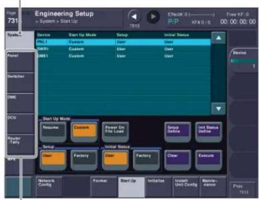
Settings in these menus are saved.
The data saved as "Initial Status" is data relating to the state of each device, excluding the "Setup" settings.
For details about the data that is saved, refer to the User's Guide.
You can customize and save user default settings to recall the same operation state when power is turned on. Or you can recall saved user settings to return to a known state if an error occurs. Data settings can also be saved as a backup on USB flash memory or other removable disks.
Notes
When shipped, the contents of user default settings in flash memory is the same as the [Factory] settings.
1 Set the state you want to save as a user default settings.
2 Display the menu.
① Open the Engineering Setup >System >Start Up menu (7314).
3 Select the target device to save.

Start Up menu
① Select switcher processor (SWR), control panel (PNL), or DME in the [Device] column.
4 Save customized data.
To save "Setup" data
①Press [Setup Define].
②Check the message, then press [Yes].
To save "Initial Status" data
①Press [Init Status Define].
②Check the message, then press [Yes].
5 Repeat steps 1 to 4 as required to set other devices.
Saving Data to Removable Disk
Setting Up a Removable Disk for Use
To use USB flash memory or other removable disk with the MVS system, you must register it as a primary device beforehand.
1 Insert the removable disk.
①Connect the USB flash memory or other removable disk to the DEVICE connector on the side of the menu panel or on the rear of the control panel.

ICP-6511 menu panel (side view)
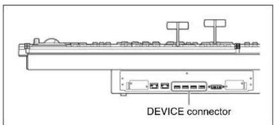
ICP-6520/6530 control panel (rear view)
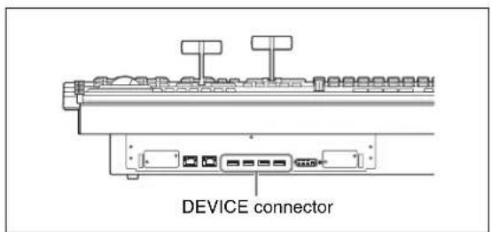
ICP-3000/3016 control panel (rear view)
2 Displaying the removable disk information.
![Total data capacity Used capacity Mount Point Set Current Aug 1 17:00:23 2/12 Set Aug 1 16:59:00 2/12 Free capacity Mount Point Pr. Size (KB) Used (KB) Free (KB) Device = = = = = = = = = = = = = = = = = = = = = = = = = = = = = = = = = = = = = = = = = = = = = = = = = = = = = = = = = = = = = = = = = = = = = = = = = = = = = = = = = = = = = = = = = = = = = = = = = = = = = = Size (KB) Used (KB) Free (KB) Device =dev\sdb1 For displaying device information, press [Refresh] button. USB Storage Device Refresh Set Primary Format Auto Detect File Load Lock Local Disk Format Local Disk Size (MB) Used (MB) Free (MB) Setup Operation Lock Set Primary Refresh](/content/2026/05/911104/images/c5e1dc1276950dc642f7104e36c89c601e97b787ebbc7b04ea1ef7a8e97080ed.jpg)
Maintenance menu
① Open the Engineering Setup >System >Maintenance menu (7317).
②In the
3 Set the removable disk as a primary device.
① Select the removable disk to be set in the [Mount Point] column.
②In the
Notes
If the removable disk is not set as a primary device, [Removable Disk] cannot be selected in the File menu.
Memo
In the

Saving/Recalling User Settings on Removable Disks
You can save customized user default ("Setup" and "Initial Status") data to USB flash memory or other removable disk and recall it when required.
This section describes the procedure for operations for the "Setup" data file.
Memo
You can save register data containing snapshots, keyframes, macros and other data on a removable disk and then recall that data.
For details about operation, refer to the User's Guide.
1 Prepare a removable disk.
For details about configuring a removable disk for use in the MVS system, see "Setting Up a Removable Disk for Use" (p. 41).
2 Display the menu.
①Open the File >Setup, Init, KMem >Setup menu (7111).
Memo
For operations for the "Initial Status" data file, open the File >Setup, Init, KMem >Initial Status menu (7112).
3 Select the target device.

flowchart
graph TD
    A["Device selection area"] --> B["Register"]
    A --> C["Removable Disk"]
    B --> D["No Name Item 1 SETUP 10"]
    C --> E["No Name Item"]
    D --> F["File Edit ALL"]
    E --> G["File Edit ALL"]
    F --> H["Load"]
    G --> I["Load → Save"]
    H --> J["Save"]
    I --> J
Setup menu
①In the device selection area on the left, select the target device.
Register: Switcher memory area (RAM)
Local Disk: Internal flash memory drive in the control panel
Removable Disk: USB-compatible external storage device (USB memory, etc.)
In this example, select [Register] to save the customized data stored in the switcher memory area (RAM).
②In the device selection area on the right, select [Removable Disk] and then select [SYSTEM] (default directory).
Memo
You can also create an arbitrary directory on the removable disk.
4 Execute a save or recall operation.
To save data
①Press [→ Save].
To recall data
①In the [Removable Disk] list on the right, select the file you want to recall.
②Press [← Load].
Setting Simple Connection of AUX Bus Remote Panel
Connecting the MKS-8080/8082 AUX Bus Remote Panel to the control panel using an S-Bus data link normally requires an HKSP-R80 Routing Switcher Controller Board or similar primary station and various connection settings. However, using a simple connection, the MKS-8080/8082 can be connected directly without the need for an S-Bus data link primary station.
A simple connection is possible if the following conditions are satisfied.
• There are no devices other than the control panel and MKS-8080/8082 connected on the S-Bus data link.
- There are no more than 16 MKS-8080/8082 units connected on the S-Bus data link.
For information about the input signals and buses that can be controlled by the MKS-8080/8082, see "Input/outputs for MVS-6520/6530/3000A/3000 system assigned to S-Bus matrix" (p. 29).
For details about the setting status of the AUX bus remote panel for a simple connection, refer to the User's Guide.
1 Initialize the MKS-8080/8082 settings.
①Press and hold down the [X-HOLD] and [KEY] buttons (MKS-8080) or the [XPT HOLD] and [LOCK (CHOP)] buttons (MKS-8082) simultaneously for five seconds.
After "Reset" is displayed in the preset display window, the MKS-8080/8082 starts to reboot and the buttons turn on (button light test).
② With the buttons turned on, press and hold down the [1] and [2] source selection buttons simultaneously. Rebooting takes approximately one minute and the MKS-8080/8082 settings are initialized.
For details about initializing settings, refer to "Making the Settings with Buttons (Setup Function)" in the MKS-8080/8082 Operation Manual.
2 Set the MKS-8080/8082 station ID.
① Initialize the MKS-8080/8082 using the procedure in step 1-①.
② With the buttons turned on, press and hold down the [1], [2], [3], and [4] source selection buttons. "ID=XXX" is displayed in the preset display window.
③ Press the source selection buttons corresponding to the station ID you want to set.
Set the station ID in the range 2 to 17.
The station ID is given by the sum of the values of the source selection buttons that are turned on.
| Source selection button | Value when button is on |
| 1 | 1 |
| 2 | 2 |
| 3 | 4 |
| 4 | 8 |
| 5 | 16 |
| 6 | 32 |
| 7 | 64 |
| 8 | 128 |
For example, turn on the [1], [2], and [4] source selection buttons (1 + 2 + 8 = 11) to set "11" for the station ID.
4 Press the [ASSIGN] button (MKS-8080) or the [ASGN] button (MKS-8082) to apply the setting.
For details about setting the station ID, refer to "Setting the station number" in "Preparations for the MKS-8080/8082" in the MKS-8080/8082 Operation Manual.
3 Set the S-Bus data link primary station role to the control panel.
Set the STATION ID switches on the front of the board in the MVS-6520/6530/3000A/3000 SLOT 8 to 001 (switch 1 only to the OPEN position).
| Switcher processor Board STATION ID switch | |
| MVS-6520/6530/3000A/3000 | CA-85 S3801 |

4 Carry out a reset.
![Device Device Start Up Mode Setup Initial Status Initialize PNL1 Custom User User SWR1 Custom User User DME1 Custom User User Initialize Reset All Clear Execute Reset Execute MVS-6520/6530/3000A screen shown. On the MVS-3000, [DME1] is not displayed.](/content/2026/05/911104/images/328b323026eb80cf560855ec370f915c9534761837e9f371179204ebf87306c5.jpg)
Initialize menu
① Open the Engineering Setup >System >Initialize menu (7315).
② Select the "PNL1" (control panel) in the [Device] column.
③In the
④Press [Execute].
⑤Check the message, then press [Yes]. This reboots the system, and connection to the MKS-8080/8082 becomes possible after the system starts.
5 Set the position of the MVS system in S-Bus space.

Router menu
① Open the Engineering Setup >Router/Tally >Router menu (7361).
②In the
③In the
④ Set each of the [Source], [Destination], and [Level] parameters to “1”.
Notes
After changing the settings, save the user default settings as required.
For details about saving data, see “Setting the Startup State” (p. 39) and “Saving Data to Removable Disk” (p. 41).
6 Export input and output signal names.

Name Export menu
① Open the Engineering Setup >Panel >Xpt Assign menu (7322).
②Press [Name Export]. The Name Export menu (7322.9) appears.
③ Select the MKS-8080/8082 station ID using the [Station ID] parameter.
Select the number (2 to 17) specified in step 2.
4 Press [Src Name Export]. The names of the switcher processor input signals are reflected on the MKS-8080/8082.
5 Press [Dest Name Export]. The names of the switcher processor output signals are reflected on the MKS-8080/8082.
Basic Image Creation Operations
Video Switching (Transitions)
Types of Transitions (Mix/NAM/Wipe/DME Wipe)
Mix
A separate video progressively fades in over the current video. The whole of the source video gradually fades out while the new video gradually fades in. The output comprises 50% of each video when the fader lever is in the center position.

natural_image
Sequence of soccer match photos showing player in blue jersey, player in white jersey, and player in black shirt (no text or symbols)Background A 50% A and 50% B output Background B
NAM (non-additive mix)
The source video and the new video images are compared, and whichever source has the highest luminance is output. The output comprises 100% of either video at each point when the fader lever is in the center position.

natural_image
Sequence of soccer match photos showing player in blue jersey and number 14 competing for a ball, followed by a referee holding a flag (no text or symbols)Background A A or B is output, whichever is brighter Background B
Wipe
The new video wipes across the screen using a wipe pattern.

natural_image
Sequence of three photos showing a soccer player in action: kicking, passing, and shooting (no text or symbols visible)Background A Background B
DME wipe
The video changes in a DME wipe pattern that uses image shrinking/magnification or other effects.

Names of Parts in the Control Panel
The positions of the principal parts and fader lever used in the following description are shown in the following figure.
ICP-6520/6530 control panel
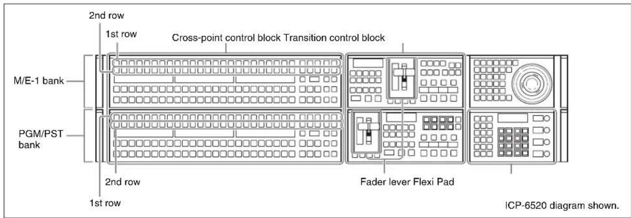
ICP-3000/3016 control panel


Video Transitions using Cuts
In a cut, the video changes with the single press of a button. The following describes the M/E-1 bank, as an example.
1 Push the fader lever up to display the background A image full-screen.

Transition control block
2 Select the video you want to display first.
①In the background A row of the cross-point control block, press the cross-point button assigned with the selected video.

Cross-point control block

natural_image
Soccer player in white jersey kicking a ball on a green field, with another player visible in the background (no text or symbols)Background A video before the transition
3 Select the video you want to display after the transition.
①In the background B row of the cross-point control block, press the cross-point button assigned with the video for post-transition.
4 Execute the transition.
①Press the [CUT] button in the transition control block.

Transition control block
The transition is executed, interchanging the cross-points in the background A and B rows.

Cross-point control block

natural_image
Man in soccer gear performing a high kick during a training exercise (no visible text or symbols)Background A video after the transition
Video Transitions using Wipes or Mixes
In a wipe or mix, the video changes gradually.
The following describes the M/E-1 bank, as an example.
1 Select the video you want to display first in the background A row, and then select the video to display post-transition in the background B row.

Cross-point control block

natural_image
Soccer player in white jersey kicking a ball on a green field, with another player blurred in background (no visible text or symbols)Background A video

natural_image
Man in gray soccer uniform performing a high kick outdoors (no visible text or symbols)Background B video
2 Select the portion of the image to change using the transition.
①Press one of the next transition selection buttons in the transition control block, turning it on.
• [BKGD] button: Changes the background.
- [KEY1] to [KEY4] buttons: Inserts (or deletes) key 1 to key 4, respectively.
In this example, press the [BKGD] button.

Transition control block
3 Select the type of transition (p. 45).
①Press one of the following transition type selection buttons, turning it on.
• [MIX] button: Go to step 5.
• [NAM] button: Go to step 5.
• [WIPE] button: Go to step 4.
• [DME] (DME wipe) button (☐ p. 50)
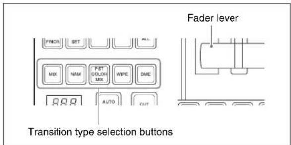
Transition control block
4 If the [WIPE] button is selected in step 3, choose a wipe pattern.
① Open the M/E-1 >Wipe >Main Pattern menu (1151).

Main Pattern menu
②Press the desired pattern to select it. In this example, select "12".
5 Set the transition rate.
①In the Flexi Pad, press the [TRANS RATE] button.
②Press the [M/E1] button, turning it on.
③ While viewing the alphanumeric display, enter the transition rate you want to set.
In this example, enter “20” (frames).
④Press the [ENTR] button.
![TRANS RATE button Alphanumeric display M/E1 button MVS-6520/3000A diagram shown. On the MVS-3000, the [DME1] and [DME2] buttons are not displayed. On the MVS-6530, the [M/E2] button is also displayed.](/content/2026/05/911104/images/1c29f8c8c66ae31299c4f0652489dc2c37f34430404e3e5165dd424ba9dd1865.jpg)
Flexi Pad
6 Execute the transition.
① Check the post-transition video on the preview monitor.
②Operate the fader lever.
In this example, pull the lever from top to bottom.

Transition control block
The output comprises 50% each of both background A video and background B video when the fader lever is in the center position.

Mid transition state
Memo
When you press the [AUTO TRANS] button, the transition is executed automatically according to the set transition rate.
Saving DME Wipe Settings in a DME Wipe Snapshot
Notes
- On the MVS-6520/6530, the optional MKS-6570 DME board is required in order to use background DME wipes.
- On the MVS-3000 and on the MVS-3000A without an MKS-6570 installed, a setting must be enabled in order to use background DME wipes.
To change the setting, see "Enabling Background DME Wipes (MVS-3000/3000A only)" (p. 39).
On the MVS-3000A with an MKS-6570 installed, configuration is not required.
Setting Picture-in-Picture (DME Wipe)
Apply a border to the picture-in-picture pattern.
The following describes the M/E-1 bank, as an example.
1 Press the [BKGD] next transition selection button, turning it on (⑤ p. 48).
2 Press the [DME] transition type selection button, turning it on ( ^① p. 48).
3 Select a DME wipe pattern.
① Open the M/E-1 >DME Wipe >1ch menu (1161).
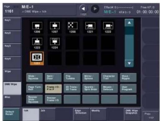
1ch menu
②Select the DME wipe pattern group. In this example, select [Frame I/O / P in P].
③Press the desired pattern to select it.
In this example, select “1251” (picture in picture) pattern.
④Move the fader lever to the top to check the video.

natural_image
Football player celebrating on a grass field with a cheering face and crowd in background (no visible text or symbols)Before adjustment
4 Set the size of the DME wipe pattern.
① Open the M/E-1 >DME Wipe >Modify menu (1165).

Modify menu
②Press [Size], turning it on.
③Adjust the [Size] parameter.
5 Set the position of the DME wipe pattern.
① In the
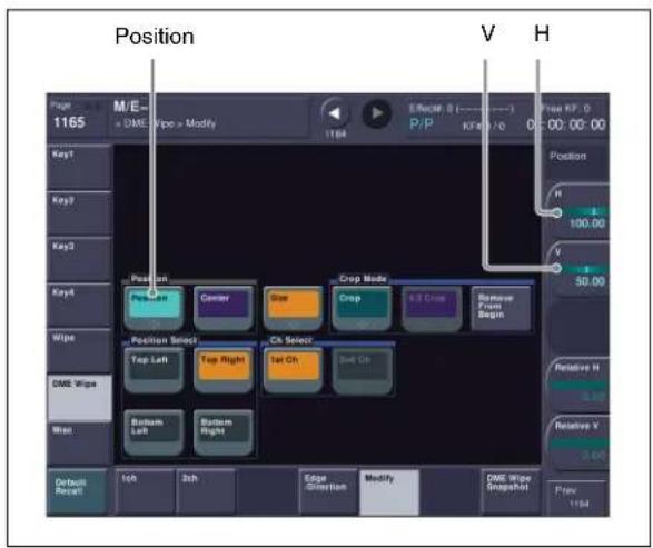
Modify menu
② Adjust the [H] parameter to set the horizontal position.
③ Adjust the [V] parameter to set the vertical position.

natural_image
Soccer player in blue jersey kicking a ball on the field, with an inset photo of a female player celebrating (no visible text or symbols)Size and position adjustment
6 Set the border.
① Open the M/E-1 >DME Wipe >Edge/Direction menu (1164).

Edge/Direction menu
②In the
③ Adjust the [Width] parameter to set the width of the border.
4 Adjust the [Luminance], [Saturation], and [Hue] parameters to set the color of the border.

natural_image
Soccer player kicking the ball on a field with a close-up of his face in the background (no text or symbols visible)
natural_image
Soccer player in blue jersey kicking the ball on a grass field, with an inset showing a close-up of his celebrating victory (no text or symbols visible)Border color setting example

Saving/Recalling a DME Wipe Snapshot
A “snapshot” is a function where the various settings required to apply a particular effect to an image are saved in memory as a set of data, for recall as required, to reproduce the original conditions.
There are various kinds of snapshot. The description in this section uses a DME wipe snapshot.
As an example, the picture-in-picture data configured in the previous section is registered as a DME wipe snapshot and then recalled to reproduce the image.
The following describes the M/E-1 bank, as an example.

natural_image
Soccer player standing on field with flag, inset shows a soccer player celebrating (no text or symbols)Recalled DME wipe pattern and border setting
1 Register the DME wipe snapshot in a button.
①In the Flexi Pad, press the [DME WIPE] button.
②Press the [M/E1] button.
③ Holding down the [DME WIPE] button, press the button you want to register (0 to 9).
The button lights yellow when successfully registered.
Notes
Buttons that are lit already have a registered DME wipe snapshot. Pressing one of these buttons will overwrite the existing contents.
![DME WIPE button 7 8 9 4 5 6 1 2 3 0 PTN NO. [0] to [9] buttons M/E1 button MVS-6520/3000A diagram shown. On the MVS-3000, the [DME1] and [DME2] buttons are not displayed. On the MVS-6530, the [M/E2] button is also displayed.](/content/2026/05/911104/images/d235912e26916302621dc29e83c76dd3b5862d38a4620853879c3859c980dc9c.jpg)
Flexi Pad
2 To check that the DME wipe snapshot is registered correctly, use another operation to alter the settings and then recall the registered DME wipe snapshot.
①Press the [DME WIPE] button.
②Press the [M/E1] button.
③ Press the button registered in step 1.
The registered DME wipe settings are immediately recalled.

Inserting Titles (Keys)
What is a Key?
You can overlay video containing a title or other material occupying part of the screen (key) over the video displayed on the whole screen (background). The component that processes keys is called a keyer.
There are four keyers available on each of the M/E and PGM/PST banks.
There are eight keyers available on the MVS-6530 PGM/PST bank only ( p. 37 ).
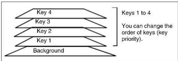
A key is comprised by a signal that describes how the background is cut out (key source) and the video signal that is inserted into that space (key fill).
Luminance keys and linear keys
These are keys that cut backgrounds using key sources generated by differences in luminance (for example, black and white).
Other keys
Chroma keys (keys that use differences in color), color vector keys (keys that use differences in color and brightness), and pattern keys (keys that use wipe patterns) are available.
Entering Titles using Luminance Keys
You can insert a title using a key.
The following describes the M/E-1 bank, as an example.
1 Select the title image.
①In the 1st row of the cross-point control block, press the [KEY1] button (button assigned to key 1), turning it on.
②In the 2nd row, select the title image (key fill).
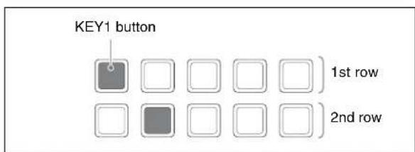
Cross-point control block

Title image
2 Select the background.
① In the background A row, press a cross-point button to select a background.

natural_image
Person celebrating with raised arms against a blue sky background (no text or symbols visible)Background

3 Select the keyer, key source, and key type.
①In the Flexi Pad, press the [KEY ADJ] button, turning it on.
②Press the [M/E1] button, turning it on.
③Press the [KEY1] button, turning it on.
④Press the [LUM] button, turning it on.
⑤Press the [AUTO SEL] button, turning it on. This uses the signals assigned in pairs as the key source.
![KEY ADJ button KEY1 button M/E1 button AUTO SEL button LUM button MVS-6520/3000A diagram shown. On the MVS-3000, the [DME1] and [DME2] buttons are not displayed. On the MVS-6530, the [M/E2] button is also displayed.](/content/2026/05/911104/images/6b0679dae9b54199b50a75fa987c6486255efe527850ff441db06ad1b663959a.jpg)
Flexi Pad

natural_image
Simple white rounded rectangle on black background (no text or symbols)Key source (assigned in signal pair) for title video
4 Insert the key.
① Check the post-insertion video on the monitor assigned beforehand for key preview output.
For details about key preview output, refer to the User's Guide.
②Press the [KEY1 ON] button in the transition control block.
Memo
To insert the key using an auto transition, press the [KEY1 TRANS] button.

Transition control block

5 Insert keys 2 to 4.
① Repeat step 1 and select the key 2 image. Press the [KEY2] button on the 1st row of the cross-point control block and select the image in the 2nd row.
2 Repeat step 3 to configure key 2.
Press the [KEY2] button on the Flexi Pad, and set the key source and key type.
③ Repeat step 4 to insert key 2.
Press the [KEY2 ON] button or [KEY2 TRANS] button on the transition control block.
④ Configure key 3 and key 4, as required.

6 Change the key display priority.
①In the transition control block, press and hold the [PRIOR SET] button and press the [KEY1] button. The title on key 1 is displayed frontmost.
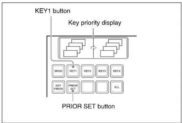
flowchart
graph TD
    A["KEY1 button"] --> B["Key priority display"]
    B --> C["Key1"]
    B --> D["Key2"]
    B --> E["Key3"]
    B --> F["Key4"]
    C --> G["BKG0"]
    D --> H["KEY1"]
    E --> I["KEY2"]
    F --> J["KEY3"]
    G --> K["PRIOR SET"]
    H --> L["PRIOR SET"]
    I --> M["PRIOR SET"]
    J --> N["PRIOR SET"]
    K --> O["ALL"]
Transition control block

Key 1 and key 2 priority changed
Composing Images using Chroma Keys
Combine images of people and scenery using keys. The following describes key 1 on the M/E-1 bank, as an example.
1 Select the key video.
① In the 1st row of the cross-point control block, press the [KEY1] button, turning it on.
②In the 2nd row, select the key video (foreground).
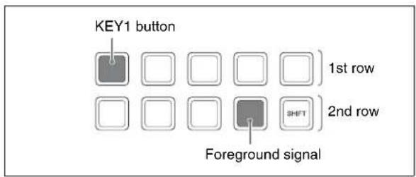
Cross-point control block

natural_image
Portrait of a man in a suit and tie against a solid blue background (no text or symbols visible)Foreground video (blue background)
2 Select the background.
①In the background A row, press a cross-point button to select a background.
natural_image
Exterior view of a large stadium with an arched roof and crowd seating (no visible text or signage)Background video
3 Select the keyer, key signal, and key type.
①In the Flexi Pad, press the [KEY ADJ] button, turning it on.
②Press the [M/E1] button, turning it on.
③Press the [KEY1] button, turning it on.
④Press the [CRK] button, turning it on.
![KEY ADJ button KEY1 button KEY1 M/E1 button CRK button MVS-6520/3000A diagram shown. On the MVS-3000, the [DME1] and [DME2] buttons are not displayed. On the MVS-6530, the [M/E2] button is also displayed.](/content/2026/05/911104/images/d6a2fa3399171b267f4aaf2d11002d750ea11038e20e18420767bc6303c3fdee.jpg)
Flexi Pad
4 Execute auto chroma key.
①Press the [SMPL MARK] button, turning it on. The foreground video only is output.
②Adjust the size and position of the sample mark using the adjustment knobs to specify the blue portion of the background.
③Press the [AUTO STRT] button.
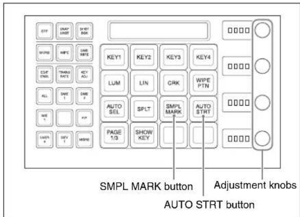
Flexi Pad

natural_image
Man in suit standing in front of a stadium with crowd (no visible text or symbols)Composited video using chroma keying
Memo
It is possible to move and magnify/shrink the key using a resizer or DME.
The material contained in this manual consists of information that is the property of Sony Corporation and is intended solely for use by the purchasers of the equipment described in this manual.
Sony Corporation expressly prohibits the duplication of any portion of this manual or the use thereof for any purpose other than the operation or maintenance of the equipment described in this manual without the express written permission of Sony Corporation.
Trademarks
The products or system names appearing in this document are trademarks or registered trademarks of their respective owners.
Further, the ® or ™ symbols are not used in the text.
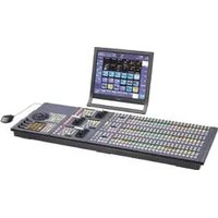

- MVS-6520 System MVS-6530 System MVS-3000A System MVS-3000 System
- NOTICE TO USERS
- Table of Contents
- Overview
- Connection
- Preparation
- Basic Image Creation Operations
- Introduction
- System name and nomenclature
- Illustrations and screenshots
- Names of Parts
- MVS-6520/6530/3000A/3000 Multi Format Switcher Processor
- Rear panel: MVS-6530
- ①~AC IN (AC power input) A and B connectors (3-pin)
- ② (signal ground) terminal
- ③PRIMARY INPUTS
- ④ OUTPUTS
- ICP-6520/6530/3000/3016 Control Panel
- Rear panel
- ICP-6511 Menu Panel
- Bottom panel
- ①DEVICE connector (USB 2.0, USB Type-B)
- ②DVI-D connector
- ③DC IN connector
- Side panel
- DEVICE connector (USB 2.0, USB Type-A)
- System Configuration
- Video Input/Output Systems
- Connecting Devices
- Notes
- MVS System Connection
- Connect the power supply.
- Switcher processor
- Control panel
- Menu panel
- To use the tally
- To use an external monitor for menu operations
- Preparation Procedure
- System settings
- Signal settings
- Other settings
- Turning Power On/Off
- Screen saver and panel sleep mode
- To turn the power off
- Opening Menus
- Memo
- Configuring the Network
- Setting the Control Panel Type
- Setting Signal Formats
- Setting the Signal Format
- Display the menu.
- Set the formats.
- Set the input reference signal.
- Setting the Screen Aspect Ratio
- Assigning Signals to Cross-Point Buttons
- Setting the Signal Name
- Assigning Pair Signals to Cross-Point Buttons
- Assigning M/E Reentry Input Signals to Cross-Point Buttons
- Assigning Output Signals
- Setting Monitor Outputs
- Set a monitor for preview output.
- Using Multi Viewer
- Setting Multi Viewer Output
- Set the multi viewer outputs.
- Configuring Multi Viewer
- Set the display method of the screen.
- Assigning Signals to Subscreens
- Setting Multi Viewer Tally Output
- Setting Tally
- Setting Parallel Tally
- Setting Serial Tally
- Set the serial tally output.
- Input/outputs for MVS-6520/6530/3000A/3000 system assigned to S-Bus matrix
- Matrix size: 128 x 128
- Assigning 8-Keyer Buttons
- (MVS-6530 only)
- Assigning Key 5 to Key 8 to 1st Row Buttons
- Assigning Key Selection Functions to Next Transition Selection Buttons
- Enabling Background DME Wipes
- (MVS-3000/3000A only)
- Setting the Startup State
- Selecting the Startup Mode at Power On
- Factory default settings
- Customizing the User Default Settings
- Save customized data.
- Saving Data to Removable Disk
- Setting Up a Removable Disk for Use
- Insert the removable disk.
- Displaying the removable disk information.
- Set the removable disk as a primary device.
- Saving/Recalling User Settings on Removable Disks
- Setting Simple Connection of AUX Bus Remote Panel
- Carry out a reset.
- Set the position of the MVS system in S-Bus space.
- Export input and output signal names.
- Video Switching (Transitions)
- Types of Transitions (Mix/NAM/Wipe/DME Wipe)
- Mix
- NAM (non-additive mix)
- Wipe
- DME wipe
- Names of Parts in the Control Panel
- Video Transitions using Cuts
- Video Transitions using Wipes or Mixes
- Set the transition rate.
- Execute the transition.
- Saving DME Wipe Settings in a DME Wipe Snapshot
- Setting Picture-in-Picture (DME Wipe)
- Saving/Recalling a DME Wipe Snapshot
- Inserting Titles (Keys)
- What is a Key?
- Luminance keys and linear keys
- Other keys
- Entering Titles using Luminance Keys
- Composing Images using Chroma Keys
- Trademarks
Brand : SONY
Model : ICP-3016
Category : Video switch