
CMTS01 - Multimeter Mercury - Free user manual and instructions
Find the device manual for free CMTS01 Mercury in PDF.


| Product Type | Digital Multimeter |
| Brand | Mercury |
| Model | CMTS01 |
| Display | LCD, 2000 counts |
| DC Voltage Range | 200 mV to 600 V |
| AC Voltage Range | 200 mV to 600 V |
| DC Current Range | 200 µA to 10 A |
| AC Current Range | 200 µA to 10 A |
| Resistance Range | 200 Ω to 20 MΩ |
| Diode Test | Yes |
| Continuity Test | Yes (buzzer) |
| Dimensions | 150 x 70 x 35 mm |
| Weight | 200 g |
| Power Supply | 9V battery (6F22) |
| Auto Power Off | Yes (after 15 min) |
| Data Hold | Yes |
| Safety Rating | CAT II 600V |
| Accessories Included | Test leads, 9V battery, user manual |
| Maintenance | Wipe with dry cloth; do not use solvents |
| Spare Parts Available | Test leads, battery, fuse (F250mA/250V) |
Frequently Asked Questions - CMTS01 Mercury
User questions about CMTS01 Mercury
0 question about this device. Answer the ones you know or ask your own.
Ask a new question about this device
Download the instructions for your Multimeter in PDF format for free! Find your manual CMTS01 - Mercury and take your electronic device back in hand. On this page are published all the documents necessary for the use of your device. CMTS01 by Mercury.
USER MANUAL CMTS01 Mercury
Please read this manual thoroughly and ensure all contents are fully understood before using the apparatus.
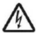
Warning
To avoid possible electric shock or personal injury, and to avoid possible damage to the tester or to the equipment under test, adhere to these following rules:
- Before using the tester inspect the case. Do not use the tester if it is damaged or the case (or part of the case) is removed. Look for cracks or missing plastic. Pay attention to the insulation around the connectors.
- Inspect the test leads for damaged insulation or exposed metal. Check the test leads for continuity.
- Do not apply more than the rated voltage, as marked on the tester, between the terminals or between any terminal and grounding.
- When the tester is working at an effective voltage over 60V in DC or 30Vrms in AC, special care should be taken for there is danger of electric shock.
• Always use the proper terminals and function for your measurements.
- Do not use or store the tester in an environment of high temperature, humidity, explosive, flammable, damp or of a strong magnetic field. The performance of the tester may deteriorate after being exposed to any of these elements.
- When using the test leads, keep your fingers behind the finger guards.
- Disconnect circuit power and discharge all high-voltage capacitors before testing resistance, continuity, diodes.
- Replace the battery as soon as the low battery indicator 📄 appears. With a low battery, the meter may produce false readings that can lead to electric shock and personal injury.
- Remove the connection between the testing leads and the circuit being tested and turn the meter power off before opening the meter case.
- The internal circuit of the meter shall not be altered at will to avoid damage of the meter and any accident.
- A soft cloth and mild detergent should be used to clean the surface of the tester on a regular basis. No abrasive and solvent should be used to prevent the surface of the tester from corrosion or damage.
- The tester is suitable for indoor use only.
- Turn the tester power off when it is not in use and take out the battery when not using for a long time. Check the battery regularly; replace the battery immediately if any signs of leaking appear. Battery acid will damage the tester.
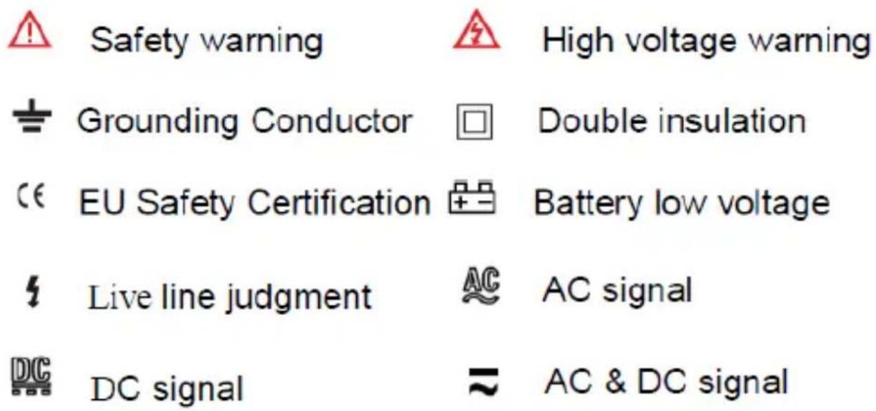
Electrical & LCD Symbols




General Specifications
Display: LCD, 6000 counts updates 2/sec
LCD Size: 35 x 25mm
Polarity Indication: “-” displayed automatically
Over-range Indication: "OL" displayed
Low Battery Indication: " + - " displayed
Range select: auto or manual
Operation Temperature: 0°C to 40°C, less than 80%RH
Storage Temperature: -10°C to 50°C, less than 85%RH
Battery Type: 1.5V x 2, AAA size
Jaw Size: 30mm
Dimension(H×W×D): 187×65×24mm
Weight: Approx 50g with battery
Technical Specifications
Accuracy is guaranteed for 1 year 23^ ± 5^ less than 80% RH
DC Voltage
| RANGE | RESOLUTION | ACCURACY |
| 500mV | 0.1mV | ±(0.8% of rdg + 5 digits) |
| 6V | 1mV | ±(0.8% of rdg + 3 digits) |
| 60V | 10mV | |
| 600V | 1V | ±(1.0% of rdg + 5 digits) |
Note: Voltages below 500mV cannot be accurately measured
Input Impedance: 10MΩ
Overload Protection: 600V DC or 600AC rms
Max. Input voltage: 600V DC
AC Voltage (auto ranging)
| RANGE | RESOLUTION | ACCURACY |
| 500mV | 0.1mV | ±(1.2% of rdg + 8 digits) |
| 6V | 1mV | ±(1.0% of rdg + 8 digits) |
| 60V | 10mv | |
| 600V | 1V | ±(1.2% of rdg + 8 digits) |
Note: Voltages below 500mV cannot be accurately measured.
Input Impedance: 10MΩ
Frequency Range: 40Hz\~400Hz
Overload Protection: 600V DC or 600V AC rms
Response: Average, calibrated in rms of sine wave
Max. Input voltage: 600V AC rms
AC Current
| RANGE | RESOLUTION | ACCURACY |
| 0.3A | 10mA | ±(2.0% of rdg + 10 digits) |
| 2A | 10mA | |
| 20A | 10mA | ±(3.0% of rdg + 5 digits) |
| 200A | 100mA | |
| 600A | 1A |
Measuring voltage drop: 200mV
Frequency Range: 40 to 200Hz
Note: As the lowest calibration point is set to 10A, the accuracy measurement below 20A is only for reference, and the accuracy below 03A cannot be measured.
Resistance (auto ranging)
| RANGE | RESOLUTION | ACCURACY |
| 60Ω | 0.001Ω | ±(1.5% of rdg + 5 digits) |
| 60Ω | 0.01Ω | |
| 600Ω | 0.1Ω | |
| 6kΩ | 1Ω | |
| 60kΩ | 100Ω | |
| 6MΩ | 1kΩ | |
| 60MΩ | 10kΩ |
Open Circuit Voltage: about 0.25V
Overload Protection: 250V DC/AC rms
Diode and Continuity
| RANGE | INTRODUCTION | REMARK |
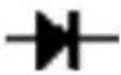 | The approx. forward voltage drop will be displayed | Open circuitVoltage:about 3V |
 | The built-in buzzer will sound if the resistance is less than about 30Ω | Open circuitVoltage:about 3V |
Overload protection: 250V DC/AC rms
For continuity test: When the resistance is between 30Ω
and 100 , the buzzer may sound or may not sound. When the resistance is more than 100 , the buzzer won't sound.
Frequency
| RANGE | ACCURACY |
| 0~10KHz (clamp) | ±(1.5% of rdg + 5 digits) |
Overload Protection: 250V DC/AC rms
Capacitance
| RANGE | ACCURACY |
| 6nF/60nF/600nF/6uF60uF/60mF (15Sec) | ±(5.0% of rdg + 8 digits) |
Overload Protection: 250V DC/AC rms
Operating Instructions
Turning on and off meter: Press and hold the power button ⏻ to turn on the meter, the meter will beep, and the LCD will display Auto symbol, indicating that the meter has entered the test state of automatically identifying the type of the measured signal. The AUTO symbol displayed on the top of the LCD means that the measured signal is in the auto range measurement mode.
Automatic Identify Mode
Insert the black lead into the COM jack and the red lead into the INPUT jack. The meter can auto identify whether the measured signal is voltage or resistance. The red lead should be connected to the positive pole of the measured signal, otherwise the negative polarity symbol will appear. If the measured voltage signal is less than 500mV AC/DC, the meter cannot identify. If there is AC current flowing through the measured wire of the meter clamp, the meter will enter the state of auto current measurement, and the current measurement is the mode of auto range.
Voltage & Resistance Measurement
When the meter identifies the signal as voltage, the meter can auto identify the AC or DC voltage signal. During measurement, the LCD directly displays the voltage reading, and the red lead indicates the polarity of the DC voltage signal. When the meter identifies the AC voltage signal, the LCD directly displays the reading of AC voltage and displays the symbol of AC voltage. When the meter identifies the signal as resistance, the LCD displays the reading of resistance. When the test resistance is less than 50 , the meter will emit a beep, indicating that the circuit under test is in short circuit state. When the measured voltage exceeds 600V, the meter will issue a warning sound, and the LCD displays the over range status OL.
Current Measurement
During AC current measurement, ensure that the wire under test is in
working condition. Please open the trigger of the clamp head and clamp only one wire also try to make the wire perpendicular to the center of the clamp head to get a more accurate value. The reading on the display is the value of the AC current flowing through the conductor. Note: When more than two wires are clamped, the measurement will not be carried out normally. In general there are many wires in the cable, so the meter needs to find the separated wire to the terminal for measurement.
Manual Selection of Functions
Press the SELECT button to enter the manual testing state, press this button successively, and the meter will enter the test state of NCV (non-contact voltage), capacitance and frequency. The LCD will display the corresponding function symbol identifier. Press this button again to enter the state of smart identification of test signal. Note: Resistance and voltage can only be tested in smart identification state.
Manual Testing Tips
Under the above conditions, you need to carefully determine the type of input model, select the correct measurement function on the meter, and connect the lead to the object to be measured in parallel. The reading displayed on the meter is the reading of the input signal.
Continuity Test
In manual function selection mode, the meter will beep when the test resistance is less than 50 , At the same time, the light on the meter will be continuously lit.
Capacitance Measurement
Press the SELECT button repeatedly to choose the capacitance function and the LCD will display nF icon. Connect the black test lead to the "COM" jack and the red to the "INPUT" jack. Connect test leads across the capacitor to measure and be sure the polarity of the connection is observed.
Note: When the capacitance under measurement is above 100uF, the meter needs at least 10 seconds to display a stable reading.
NCV (Non-Contact-Voltage) Test
In Auto mode press the SELECT button repeatedly to select NCV function, the LCD will display EF only. "NCV" means "non-contact voltage detection" without the use of test leads. Use the orange probe on top of the meter jaws to test the target. When an AC voltage of 30\~1000V is detected, the meter will make a continuous sound, and the LCD will display the number of bars to indicate the voltage intensity.
Frequency Measurement
In AUTO mode, press the SELECT button repeatedly to select the Frequency function and the LCD will display Hz only. Connect the black test lead to the "COM" jack and the red to the "INPUT" jack. Connect test leads to the signal carrier to be measured in parallel and the meter will then display the frequency.
Back Light and Hold Functions
Press the 🔊 button for more than one second to enter the LCD screen backlight mode. Repeat the process to turn off the backlight function. A short press of the same button will hold the current reading on the LCD screen for recording etc. Only when you short press the button again can the meter be used for a new measurement function.
Auto Power Off (APO) Function
The meter is fitted with an APO function to save battery wastage. This function will switch off the meter after around 15 minutes of inactivity.
Battery Replacement
The + - symbol on the display indicates the batteries are running low and
need replacing. Remove the small screw on the bottom of the battery cover and replace the 2 AAA batteries, ensuring you have the correct polarity for each battery. Replace the cover and screw to secure the unit.
Accessories
- Remote cable test unit
- Set of test leads (red and black)
- 2pcs AAA batteries
- Instruction manual

This product is classed as Electrical or Electronic equipment and should not be disposed with other household or commercial waste at the end of its useful life. The goods must be disposed of according to your local council guidelines.
Errors and omissions excepted.
Copyright© 2023 AVSL Group Ltd, Unit 2 Bridgewater Park, Taylor Road, Trafford Park, Manchester. M41 7JQ.
AVSL (Europe) Ltd, Unit 3D North Point House, North Point Bus. Park, New Mallow Road, Cork, Ireland.

- Please read this manual thoroughly and ensure all contents are fully understood before using the apparatus.
- Warning
- Electrical & LCD Symbols
- General Specifications
- Technical Specifications
- AC Voltage (auto ranging)
- Operating Instructions
- Automatic Identify Mode
- Voltage & Resistance Measurement
- Current Measurement
- Manual Selection of Functions
- Manual Testing Tips
- Continuity Test
- Capacitance Measurement
- NCV (Non-Contact-Voltage) Test
- Frequency Measurement
- Back Light and Hold Functions
- Auto Power Off (APO) Function
- Battery Replacement
- Accessories
- Errors and omissions excepted.
Brand : Mercury
Model : CMTS01
Category : Multimeter