
MTB01 - Multimeter Mercury - Free user manual and instructions
Find the device manual for free MTB01 Mercury in PDF.


| Product Type | Digital Multimeter |
| Brand | Mercury |
| Model | MTB01 |
| Display | LCD, 3 1/2 digits (1999 counts), 0.5" high |
| Polarity Indication | Automatic, minus sign displayed |
| Measurement Method | Double integral A/D switch implement |
| Sampling Speed | 2 times per second |
| Overload Indication | "1" displayed |
| Operating Environment | 0°C to 40°C, <80% RH |
| Storage Environment | -10°C to 50°C, <85% RH |
| Power Supply | 9V battery (NEDA 1604 or 6F22) |
| Low Battery Indication | "+ -" symbol appears |
| Static Current | About 4 mA |
| Dimensions | 126 x 70 x 26 mm |
| Weight | 108 g (including battery) |
| DC Voltage Ranges | 200mV, 2000mV, 20V, 200V, 500V |
| AC Voltage Ranges | 200V, 500V (45-450Hz) |
| DC Current Ranges | 200μA, 2000μA, 20mA, 200mA, 5A |
| Resistance Ranges | 200Ω, 2000Ω, 20kΩ, 200kΩ, 2000kΩ |
| Continuity Test | Audible buzzer if resistance <30±20Ω |
| Diode Test | Forward voltage drop in mV |
| Transistor hFE Test | Base current 10μA, V_CE approx. 2.8V |
| Accessories Included | Test leads (red & black), 9V battery, manual |
Frequently Asked Questions - MTB01 Mercury
User questions about MTB01 Mercury
0 question about this device. Answer the ones you know or ask your own.
Ask a new question about this device
Download the instructions for your Multimeter in PDF format for free! Find your manual MTB01 - Mercury and take your electronic device back in hand. On this page are published all the documents necessary for the use of your device. MTB01 by Mercury.
USER MANUAL MTB01 Mercury
Please read this manual thoroughly and ensure all contents are fully understood before use of the apparatus.
Warning
To avoid possible electric shock or personal injury, and to avoid possible damage to the Meter or to the equipment under test, adhere to the following rules:
Before using the Meter inspect the case. Do not use the Meter if it is damaged or the case (or part of the case) is removed. Look for cracks or missing plastic. Pay attention to the insulation around the connectors.
Inspect the test leads for damaged insulation or exposed metal. Check the test leads for continuity.
Do not apply more than the rated voltage, as marked on the meter, between the terminals or between any terminal and grounding.
The rotary switch should be placed in the right position and no changeover of range shall be made during measurement being conducted to prevent damage of the Meter.
When the meter working at an effective voltage over 60V in DC or 30Vrms in AC, special care should be taken for there is danger of electric shock.
Use the proper terminals, function, and range for your measurements.
Do not use or store the meter in an environment of high temperature, humidity, explosive, inflammable, and strong magnetic field. The performance of the meter may deteriorate after dampened.
When using the test leads, keep your fingers
behind the finger guards.
➢ Disconnect circuit power and discharge all high-voltage capacitors before testing resistance, continuity, diodes or hFE.
Replace the battery as soon as the battery indicator 📁 appears. With a low battery, the meter may produce false readings that can lead to electric shock and personal injury.
Remove the connection between the testing leads and the circuit being tested and turn the meter power off before opening the meter case.
The internal circuit of the meter shall not be altered at will to avoid damage of the meter and any accident.
Soft cloth and mild detergent should be used to clean the surface of the meter in regular basis. No abrasive and solvent should be used to prevent the surface of the meter from corrosion, damage and accident.
The meter is suitable for indoor use only.
➢ Turn the meter power off when it is not in use and take out the battery when not using for a long time. Check the battery at regular basis as it may leak when it has been using for some time, replace the battery as soon as leaking appears. A leaking battery will damage the meter.
General Specifications
Max display: LCD 3 1/2 digits (1999 count) 0.5" high
Polarity: Automatic, indicated minus, assumed plus.
Measure method: double integral A/D switch implement.
Sampling speed: 2 times per second
Over-load indication: "1" is displayed
Operating Environment: 0°C\~40°C, at <80%RH
Storage Environment: -10°C\~50°C, at <85%RH
Power: 9V NEDA 1604 or 6F22
Low battery indication: " "+ -
Static electricity: about 4mA
Product Size: 126 x 70 x 26mm
Product net weight: 108g (including battery)
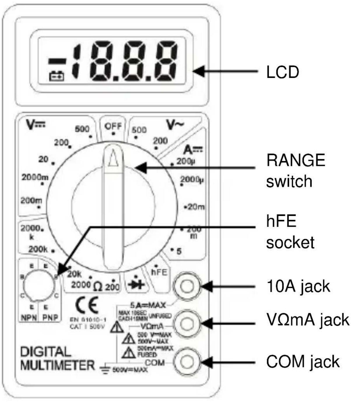
Series Multimeters Function Table
| MODEL DCV ACV DCA OHM hFE | ||||||||||
| MTB01 | √ | √ | √ | √ | √ | √ | √ | √ | ||
| MTB02 | √ | √ | √ | √ | √ | √ | ||||
Technical Specifications
Accuracies are guaranteed for 1 year, 23^ ± 5^ , less than 80% RH
DC VOLTAGE
| RANGE RESOLUTION ACCURACY | ||
| 200mV | 100uV ±(0.5% of rdg + 3D) | |
| 2000mV | 1mV | ±(0.8% of rdg + 5D) |
| 20V | 10mV | |
| 200V | 100mV | |
| 500V | 1V | ±(1.0% of rdg + 5D) |
OVERLOAD PROTECTION: 220V rms AC for 200mV range and 500V DC or 500Vrms for all ranges.
AC VOLTAGE
| RANGE | RESOLUTION | ACCURACY |
| 200V | 100mV | ±(2.0% of rdg +10D) |
| 500V | 1V |
RESPONSE: Average responding, calibrated in rms of a sine wave.
FREQUENCY RANGE: 45Hz \~ 450Hz
OVERLOAD PROTECTION: 500V DC or 500V rms for all ranges.
AUDIBLE CONTINUITY
| RANGE | DESCRIPTION |
| Built-in buzzer sounds if resistance is less then 30±20Ω |
OVERLOAD PROTECTION:15 seconds maximum 220Vrms.
DC CURRENT
| RANGE | RESOLUTION ACCURACY | |
| 200uA | 100nA | ±(1.8% of rdg +2D) |
| 2000uA | 1uA | |
| 20mA | 10uA | |
| 200mA | 100uA ±(2.0% of rdg +2D) | |
| 5A | 10mA ±(2.0% of rdg +10D) | |
OVERLOAD PROTECTION: F0.5A/250V and F5A/250V fuse
MEASURING VOLTAGE DROP: 200mV
RESISTANCE
| RANGE | RESOLUTION ACCURACY | |
| 200Ω | 0.1Ω ±(1.0% of rdg +10D) | |
| 2000Ω | 1Ω | ±(1.0% of rdg +4D) |
| 20KΩ | 10Ω | |
| 200KΩ | 100Ω | |
| 2000KΩ | 1KΩ | |
MAXIMUM OPEN CIRCUIT VOLTAGE: 3V. OVERLOAD PROTECTION: 15 seconds maximum 220Vrms.
OPERATING INSTRUCTIONS DC & AC VOLTAGE MEASUREMENT
- Connect red test lead to "VΩmA" jack, Black lead to "COM" jack.
- Set RANGE switch to desired VOLTAGE position, if the voltage to be measured is not known beforehand, set switch to the highest range and reduce it until satisfactory reading is obtained.
- Connect test leads to device or circuit being measured.
- Turn on power of the device or circuit being measured voltage value will appear on Digital Display along with the voltage polarity.
DC CURRENT MEASUREMENT
- Red lead to "VΩmA". Black lead to "COM" (for measurements between 200mA and 5A connect red lead to "5A" jack with fully depressed.)
- Set RANGE switch to desired DCA position.
- Open the circuit to be measured, and connect test leads in SERIES with the load in with current is to measure.
- Read current value on Digital Display.
- Additionally, "5A" function is designed for intermittent use only. Maximum contact time of the test leads with the circuit is 10 seconds, with a minimum intermission time of 15 minutes between tests.
RESISTANCE MEASUREMENT
- Red lead to "VΩmA". Black lead to "COM".
-
Set RANGE switch to desired position.
-
If the resistance being measured is connected to a circuit, turn off power and discharge all capacitors before measurement.
- Connect test leads to circuit being measured.
- Read resistance value on Digital Display.
DIODE MEASUREMENT
- Red lead to "VΩmA", Black lead to "COM".
- Set RANGE switch to " " position.
- Connect the red test lead to the anode of the diode to be measured and black test lead to cathode.
- The forward voltage drop in mV will be displayed. If the diode is reversed, figure "1" will be shown.
TRANSISTOR hFE MEASUREMENT
- Set RANGE switch to the hFE position.
- Determine whether the transistor is PNP of NPN type and locate the Emitter, Base and Collector leads. Insert the leads into the proper holes of the hFE Socket.
- The meter will display the approximate hFE value at the condition of base current 10 A and V_CE 2.8 ~V .
AUDIBLE CONTINUITY TEST
- Red lead to "VΩmA", Black lead to "COM".
- RANGE switch to " " position.
- Connect test leads to two points of circuit to be tested. If the resistance is lower then 30 ± 20 , the buzzer will sound.
BATTERY AND FUSE REPLACEMENT
Fuse rarely need replacement and blow almost always as a result of operator error.
If “” appears in display, it indicates that the battery should be replaced.
To replace battery & Fuse (F500mA/250V for mA terminal and F5A/250V for 5A terminal) remove the 2 screws in the bottom of the case, simply remove the old, and replace with a new one. Be careful to observe polarity.
ACCESSORIES
Operator's instruction manual
Set of test leads (red and black)
9-volt battery, NEDA 1604 6F22 type.

This product is classed as Electrical or Electronic equipment and should not be disposed with other household or commercial waste at the end of its useful life. The goods must be disposed of according to your local council guidelines.
Errors and omissions excepted.
Copyright© 2021 AVSL Group Ltd, Unit 2 Bridgewater Park, Taylor Road, Trafford Park, Manchester. M41 7JQ.
AVSL (Europe) Ltd, Unit 3D North Point House, North Point Bus. Park, New Mallow Road, Cork, Ireland.

Brand : Mercury
Model : MTB01
Category : Multimeter